1
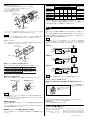
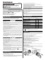
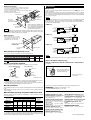
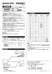
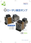
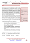
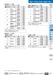
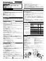
HM-4006-7
取扱説明書
超低速シンクロナスモーター
SMK シリーズ
お買い上げいただきありがとうございます。
この取扱説明書には、製品の取り扱いかたや安全上の注意事項を示しています。
● 取扱説明書をよくお読みになり、製品を安全にお使いください。
● お読みになったあとは、いつでも見られるところに必ず保管してください。
製品の取り扱いは、適切な資格を有する人が行なってください。
この製品は、一般的な産業機器の機器組み込み用として設計されています。その他の用途に
は使用しないでください。この警告を無視した結果生じた損害の補償については、当社は一切
その責任を負いませんので、あらかじめご了承ください。
For English version, see opposite side.
はじめに
使用上のご注意
この製品は、UL認定品で(インピーダンスプロテクト)、CE マーキングを自己宣言
(低電圧指令 )しています。
(ただし、SMK014A-A、SMK014A-B、SMK014MA-A、SMK014MA-B、SMK014K-A、
SMK014K-B、SMK0A-□ A、SMK0A-□ Bを除きます。)
■設置条件
過電圧カテゴリー II、汚染度 2、クラス I 機器
■有害物質 ( SMK5タイプを除く)
RoHS (EU 指令 2002/95/EC 27Jan.2003) 適合
安全上のご注意
ここに示した注意事項は、製品を安全に正しくお使いいただき、お客様や他の
人々への危害や損傷を未然に防止するためのものです。内容をよく理解してから
本文をお読みください。
警告
この警告事項に反した取り扱いをすると、死亡または重傷を負う場合がある内容
を示しています。
● 爆発性雰囲気、引火性ガスの雰囲気、腐食性の雰囲気、水のかかる場所、可燃
物のそばでは使用しないでください。
火災・感電・けがの原因になります。
● 設置、接続、運転・操作、点検の作業は、適切な資格を有する人が行なってく
ださい。
火災、感電、けがの原因になります。
● 作業をするときは、電源を切ってから行なってください。
感電の原因になります。
● モーターは筐体内に設置して、手が触れないようにするか、接地してください。
感電・けがの原因になります。
● 接続は接続図にもとづき、確実に行なってください。
火災・感電の原因になります。
● コンデンサ、外部抵抗の接続端子は、必ず絶縁処理をしてください。
感電の原因になります。
● モーターケーブルを無理に曲げたり、引っ張ったり、はさみ込んだりしないでく
ださい。
火災・感電の原因になります。
● 停電したときは、電源を切ってください。
停電復旧時にモーターが突然起動して、けが・装置破損の原因になります。
● 昇降装置に使用するときは、可動部の位置保持対策を行なってください。
モーターは電源オフ時に、保持力がなくなります。可動部が落下して、けが・装
置破損の原因になります。
● 電源を切った直後(30 秒以内)は、モーター、コンデンサの接続端子に触れない
でください。
残留電圧により、感電の原因になります。
● モーターは、分解・改造しないでください。
感電・けが・装置破損の原因になります。
注意
この注意事項に反した取り扱いをすると、傷害を負うまたは物的損害が発生する
場合がある内容を示しています。
● モーターの仕様値を超えて使用しないでください。
感電・けが・装置破損の原因になります。
● モーターの出力軸やケーブルを持たないでください。
けがの原因になります。
● 装置の故障や動作の異常が発生したときは、装置全体が安全な方向へはたらくよ
う非常停止装置、または非常停止回路を外部に設置してください。
けがの原因になります。
● モーターは、
金属板に確実に固定してください。
けが・装置破損の原因になります。
● モーターの回転部 (出力軸)に、カバーを設けてください。
けがの原因になります。
● 異常が発生したときは、ただちに運転を停止して、電源を切ってください。
火災・感電・けがの原因になります。
● 運転中および停止後しばらくの間は、
モーター、外部抵抗に触れないでください。
モーターの表面、外部抵抗が高温のため、やけどの原因になります。
● モーターは、正常な運転状態でも、表面温度が70 ℃を超えることがあります。
運転中のモーターに接近できるときは、図の警告ラベルをはっきり見える位置
に貼ってください。
やけどの原因になります。
● モーターを廃棄するときは、できるだけ分解し、産業廃棄物として処理してくだ
さい。
◆絶縁抵抗測定、絶縁耐圧試験は、
モーターとドライバそれぞれで行なってください。
製品破損の原因になります。
◆モーター出力軸を拘束しないでください。
モーター出力軸がモータートルクより大きな負荷トルクで拘束されると、起動で
きずに振動状態となりモーターの寿命を著しく低下させます。負荷トルクは必ず
モータートルク以下で使用してください。
◆グリース漏れについて
ギヤードモーターからまれに少量のグリースがにじみ出ることがあります。グリー
ス漏れによる周囲環境の汚染が問題となる場合には、定期点検時にグリースの
にじみをチェックしてください。または、油受けなどの損害防止装置を取り付け
てください。油漏れでお客様の装置や製品などに不具合を発生させる原因にな
ります。
◆許容トルクについて
モーター起動/停止時の加減速トルク、および負荷(摩擦)トルクの合計値は、許
容トルク以下に抑えて運転してください。許容トルクを超えたトルクで運転する
と、ギヤ部が破損する原因になります。
製品 の確認
パッケージを開封し、次の
ものがすべて揃っているこ
とを確認してください。
不足している場合や破損
している場合は、お買い求
めの支店、営業所までご連
絡ください。
品名中の□には、減速比を
表す数字が入ります。
モーター品名
SMK014A-A
SMK014A-B
SMK014MA-A
SMK014MA-B
SMK014K-A, SMK014K-B
SMK0A-□ A *1
SMK0A-□ B *1
コンデンサ
外部抵抗
0.6μF*2
−
12μF
−
0.6μF*2
−
SMK237A-A, SMK237A-B
1.2μF*2
SMK216A-GN, SMK216A-GNB
SMK5100A-A, SMK5100A-B 2.5μF*2
−
400Ω 30W
0.6μF*2 1500Ω 30W
*1 取り付けねじ(4 本)が SMK5160A-A, SMK5160A-B 2.5μF*2 400Ω 30W
付属しています。
SMK550A-GN, SMK550A-GNB 0.6μF*2 400Ω 30W
*2 コンデンサキャップが
2000Ω 30W
SMK550C-GN, SMK550C-GNB 0.35μF
付属しています。
SMK5100C-A, SMK5100C-B
設
置
■ 設置場所
モーターは機器組み込み用に設計、製造されています。
風通しがよく、点検が容易な次のような場所に設置してください。
◆屋内に設置された筐体内
(換気口を設けてください)
◆使用周囲温度 − 10 ℃∼ + 40 ℃
(凍結しないこと)
◆使用周囲湿度 85%以下
(結露しないこと)
◆爆発性雰囲気や有害なガス
(硫化ガスなど)および液体のないところ
◆直射日光が当たらないところ
◆じんあい、鉄粉などの少ないところ
◆水 (風雨や水滴 )、油 ( 油滴 )その他 の
液体がかからないところ
◆塩分の少ないところ
◆連続的な振動や過度の衝撃が加わら
ないところ
◆電磁ノイズ ( 溶接機、動力機器など)が
少ないところ
◆放射性物質、磁場がなく真空でないと
ころ
◆標高 1000m 以下
■ 設置方法
モーターは耐振動性にすぐれ、熱伝導効果が高い平滑な金属板に設置してください。
●丸シャフトタイプ
モーター取付面にある4 か所の取付穴 (またはタップ穴 )を使用して、4 本のボルト
(付属していません)で固定してください。
モーター取付面にあるインローは、座ぐりまたは貫通加工されたインロー受けには
め込んでください。
● SMK2、SMK5 タイプ
● SMK0 タイプ
取付板
インロー受け
(座ぐりまたは貫通穴 )
タップ穴
インロー受け
(座ぐりまたは貫通穴 )
取付板
●歯切りシャフトタイプ
モーター取付面にある4か所の取付穴(またはタップ穴)を使用
して、ギヤヘッド付属の4 本のボルトで固定してください。
ギヤヘッド取付面にあるボス部は、
座ぐりまたは貫通加工されたボス
部受けにはめ込んでください。
モーター
ボス部受け
(座ぐりまたは貫通穴 )
許容オーバーハング荷重 N
出力軸先端からの距離
モータータイプ
0mm
10mm
15mm
許容スラスト荷重
N
20mm
0.27 *2
SMK014K
ギヤヘッド
(別売り)
SMK014A
SMK014M
SMK0A *1
20
25
34
10
15
SMK237
54
67
260
290
SMK5100
ギヤヘッド
付属のねじ
インロー部
歯切りシャフト
ボス部
六角ナット
5mm
SMK5160
52
−
20
30
−
15
89
130
−
340
390
480
0.7 *2
1.7 *2
0.3 *2
2.8 *2
*1 ギヤヘッドの許容オーバーハング荷重と許容スラスト荷重です。
*2 値はモーター質量 (単位:kg )です。スラスト荷重はモーターの自重以下にしてください。
オーバーハング荷重やスラスト荷重が許容値を超えたときには、
モーターの軸受けおよび
出力軸が繰り返し荷重により、疲労破損にいたる原因になります。
接 続
取付板
■ 運転
モーターにギヤヘッドを組み付けるときは、モーターとギヤヘッドのインロー部を合
わせて、ギヤヘッドを左右にゆっくり回しながら組み付けてください。
重要
モーターとギヤヘッドを無理に組み付けたり、歯切りシャフトをギヤヘッド側板やギヤに
強く当てないでください。異常な音が出たり、ギヤヘッドの寿命が短くなります。
●ギヤードタイプ
モーター取付面にある4 か所のタップ穴を使用して、金属板との間にすき間がない
ように、付属の4 本のボルトで固定してください。
付属のコンデンサと外部抵抗(SMK5 タイプのみ)を必ず図のように接続してくだ
さい。
スイッチを「CW」側に倒すと出力軸は時計方向に回転し、
「CCW」方向に倒すと
反時計方向に回転します。電源を切るとモーターは停止します。(回転方向は、出
力軸側から見た出力軸の回転方向を表します。)
重要
歯切りシャフトタイプのモーターを使用する場合、ギヤヘッド(別売り)出力軸の回転方向
は、減速比 25、30、36 のときモーター軸と逆になります。ギヤードタイプを使用する場
合、ギヤ出力軸の回転方向は、減速比 15、18、100、120のときモーター軸と逆にな
ります。
CCW
● SMK0 タイプ
インロー受け
(座ぐりまたは貫通穴 )
CW
赤
単相24V
R0 C0
CW
白
または
単相
100/115V
青
SW
CCW
モーター
コンデンサ
R0 C0
● SMK2 タイプ
十字穴付ねじ(付属)
CCW
CW
赤
単相
100/115V
取付板
R0 C0
CW
灰
青
SW
CCW
■ ギヤヘッド( 別売り)との組み合わせ
歯切りシャフトタイプは、次のギヤヘッドと組み合わせて使用してください。
SMK550A-GN, SMK550A-GNB
SMK550C-GN, SMK550C-GNB
CCW
● SMK5 タイプ
2GN □ K, 2GN □ S
単相
100/115V
または
R0 C0
5GN □ K, 5GN □ S
単相
200/230V
SW
図に示したねじ(付属していません)を使用して、確実に取り付けてください。
〈 取付金具付きタイプ 〉
M4ねじ
コンデンサ
取付金具
5 ×φ4.3
取付足
灰
青
CCW
モーター
コンデンサ 外部抵抗
重要
■ コンデンサの取り付け
コンデンサ
CW
R0 C0
ギヤヘッド品名中の□には、減速比を表す数字が入ります。
〈 取付足付きタイプ 〉
M4ねじ
CW
赤
適合ギヤヘッド品名 ( 別売り)
モーター品名
SMK216A-GN, SMK216A-GNB
モーター
コンデンサ
R0 C0
φ4.3
スイッチ、リレーの接点保護のために、必ずサージ吸収回路を接続してください。
【コンデンサキャップの取り付け】
SMK014K-A、SMK014K-B、SMK550C-GN、SMK550C-GNBは付属してい
ません。
コンデンサ
キャップ
モーターの直流励磁につい
ては、カタログを参照してく
ださい。
リード線
L
AU
115 1
C3 P-3
CH 78 T
60
E5
コンデンサ端子にリード線を
接続後、コンデンサキャップ
を被せます。
重要
● 取付足付きタイプコンデンサのねじの締め付けトルクは、
取付足の破損防止のため
1N・m 以下にしてください。
●コンデンサは、モーターから100mm 以上離して取り付けてください。
モーターの熱で
コンデンサの寿命が短くなります。
■ 負荷の取り付け
モーターに負荷を取り付けるときは、モーター出力軸と負荷の軸中心線をそろえ
てください。
モーター出力軸にフレキシブルカップリングやプーリーを取り付けるときは、出力
軸や軸受けに損傷を与えないでください。
製品の性能、仕様および外観は改良のため予告なく変更することがありますのでご了承ください。
は、オリエンタルモーター株式会社の商標です。
© Copyright ORIENTAL MOTOR CO., LTD. 2006
L
AU
115 1
C3 P-3
CH 78 T
60
E5
http://www.orientalmotor.co.jp/
● 製品についてのご質問、
ご相談はお客様ご相談センターへお問い合わせください。フリーコール(無料)
です。
■ 許容オーバーハング荷重と許容スラスト荷重
携帯電話・PHSからもご利用が可能です。
モーター出力軸のオーバーハング荷重とスラスト荷重は、次の許容値以下に抑え
てください。
受付時間 平日 9:00∼18:30
土曜日 9:00∼17:30
東 京 TEL 0120-925-410 FAX 0120-925-601
名古屋 TEL 0120-925-420 FAX 0120-925-602
大 阪 TEL 0120-925-430 FAX 0120-925-603
この取扱説明書は再生紙を使用しています。
HM-4006-7
SMK Series
Thank you for purchasing an ORIENTAL MOTOR product.
This Operating Manual describes product handling procedures and safety precautions.
● Please read it thoroughly to ensure safe operation.
● Always keep the manual where it is readily accessible.
Only qualified personnel should work with the product.
This product is designed for incorporation in general industrial machinery, and must not be used
for another purpose. ORIENTAL MOTOR Co., Ltd. is not responsible for any damage caused
through failure to observe this warning.
Introduction
◆ About grease of the geared motor
OPERATING MANUAL
Low-Speed Synchronous Motor
This product is UL-recognized (impedance-protected ), and has made self-declaration of the
CE marking (the Low-Voltage Directive). ( This does not apply to the SMK014A-A ,
SMK014A-B, SMK014MA-A, SMK014MA-B, SMK014K-A, SMK014K-B,
SMK014K-AA , SMK0A- A and SMK0A- B.)
■ Installation conditions
Overvoltage category II, Pollution degree 2, Class I equipment
■ Hazardous substances (Excluding SMK5 type)
On rare occasions, a small amount of grease may ooze out from the geared motor. If there
is concern over possible environmental damage resulting from the leakage of grease, check
for grease stains during regular inspections. Alternatively, install an oil pan or other device
to prevent leakage from causing further damage. Oil leakage may lead to problems in the customer’s equipment or products.
◆ Allowable torque
Operate the motor by making sure the sum of the acceleration /deceleration torque at the
starting/stopping of the motor and the load (friction) torque doesn’t exceed the allowable
torque. Operating the motor in excess of the allowable torque may result in a damaged gear.
RoHS (Directive 2002/ 95/ EC 27Jan.2003) compliant
Product confirmation
Safety precautions
The precautions described below are intended to ensure the safe and correct use of the product, and to prevent the customer or others from exposure to the risk of injury.
Read the body of the text based on a sufficient understanding of its importance.
Warning
Failure to observe the warnings contained herein may result in a situation leading to serious
injury or death.
● Do not use the product in explosive or corrosive environments, in the presence of flammable
gases, locations subjected to splashing water, or near combustibles. Doing so may result in
fire, electric shock or injury.
● Qualified personnel are required for the installation, connection, operation and inspection of
this product. Failure to do so may result in fire, electric shock or injury.
● Be sure to turn off the power before installing, connecting or inspecting this product. Failure
to do so may result in electric shock.
● Install the motor in the enclosure to avoid contact with the hands, or provide sufficient grounding. Failure to do so may result in electric shock or injury.
● Connect this product securely and accurately, according to the connection diagrams. Failure
to do so may result in fire or electric shock.
● Be sure to insulate the connection terminals of the capacitor and external resistor. Failure to
do so may result in electric shock.
● Do not forcibly bend, pull or pinch the motor cable. Doing so may result in fire or electric
shock.
● In case of power failure, be sure to turn off the power. Failure to do so may cause the motor
to start suddenly when the power is restored, and could result in injury or damage to the
equipment.
● If this product is used in an elevator application, be sure to provide a measure for the position retention of moving parts. The motor loses its retentiveness when the power is turned off.
Failure to provide such a measure may cause the moving parts to fall off, resulting in injury
or damage to the equipment.
● Do not touch the connection terminals of the motor or capacitor immediately after the power
is turned off (for a period of 30 seconds). The residual voltage may cause electric shock.
● Do not disassemble or modify the motor. Doing so may result in electric shock, injury or damage to the equipment.
Caution
Failure to observe the following precautions may result in injury or property damage.
● Do not use the motor beyond the specified values. Doing so may result in electric shock,
injury or damage to the equipment.
● Do not hold the motor shaft or motor cable. Doing so may result in injury.
● Provide an emergency-stop device or emergency-stop circuit external to the equipment so that
the entire equipment will operate safely in the event of a system failure or malfunction. Failure
to do so may result in injury.
● Be sure to secure the motor onto the metal plate. Failure to do so may result in injury or damage to the equipment.
● Be sure to cover the rotating portion (motor shaft) of the motor. Failure to do so may result in
injury.
● Immediately when trouble has occurred, stop running and turn off the power. Failure to do so
may result in fire, electric shock or injury.
● Do not touch the motor or external resistor during operation or immediately after the equipment is stopped, since the surfaces of the motor and external resistor will be extremely hot.
Failure to do so may result in a burn.
● The surface temperature of the motor may exceed 70°C (158°F), even during normal operation. Be sure to attach a warning label, as shown in the figure, in a clearly visible location if
it is possible for the operator to access the motor during operation.
Failure to do so may result in a burn.
● To dispose of the motor, disassemble it into parts and components as much as possible and
dispose of individual parts/components as industrial waste.
Open the package and verify that the following items are present. If there is any shortage or
damage, contact the sales office from which you purchased the product.
Model
Capacitor
SMK014A-A, SMK014A-B
SMK014MA-A, SMK014MA-B
SMK014K-A, SMK014K-B
SMK014K-AA
SMK0A- A∗1, SMK0A- B∗1
SMK237A-A, SMK237A-B
SMK216A-GN, SMK216A-GNB
SMK5100A-A, SMK5100A-B
SMK5100A-AA, SMK5100A-BA
SMK5100C-A, SMK5100C-B
SMK5160A-A, SMK5160A-B
SMK5160A-AA, SMK5160A-BA
SMK550A-GN, SMK550A-GNB, SMK550A-GNBA
SMK550C-GN, SMK550C-GNB
0.6µF∗2
-
12µF
-
0.6µF∗2
-
1.2µF∗2
-
Failure to do so may result in equipment damage.
◆ Do not give any constraint to the motor shaft.
If the motor shaft is constrained with a load torque exceeding the motor torque, the motor cannot be started and a vibrating condition will occur, resulting in a significant decrease in motor
life. Be sure to use a load torque that is less than the motor torque.
2.5µF∗2
400 Ω
30W
0.6µF∗2
1500 Ω
30W
2.5µF∗2
400 Ω
30W
0.6µF∗2
0.35µF
400 Ω
2000 Ω
30W
30W
∗1 Mounting screws (4 pieces) are provided.
∗2 A capacitor cap is provided.
A box (
) of the model is filled with a number to represent the gear ratio.
Installation
■ Installation site
The motor is designed and manufactured for incorporation in machinery and equipment. Install
it at the site in consideration of the following to ensure effective ventilation and easy inspection:
◆ In indoor enclosure (where a ventilation port must be provided)
◆ Ambient temperature : -10°C ~ +40°C(non-freezing)
[+14°F ~ +104°F ]
◆ Ambient humidity : 85% or less (non-condensing)
◆ Not in an explosive atmosphere in the presence of hazardous gas (sulfide gas) or liquid
◆ Not at a site exposed to sunlight
◆ Not at a site exposed to dust or metallic chips and particulate matter
◆ Not subject to splashing water (rainstorm and otherwise), oils or other liquids
◆ Not at a site containing excessive salt
◆ Not subjected to continuous vibration or excessive shock
◆ Not exposed to electromagnetic noise (welders and power equipment)
◆ Not in the presence of radiation, magnetic fields or a vacuum environment
◆ At an elevation not exceeding 1,000 meters (3,300 ft.)
■ Method of installation
Install the motor on a smooth metallic plate offering a high resistance to vibration and excellent
heat-conductive properties.
● Round shaft type
Using the four installation holes (or tapped holes) located on the motor's installation surfaces,
secure the motor with four bolts (not provided).
The motor's mounting pilot on the motor-installation hole should be inserted into the mountingpilot holder, which is countersunk or drilled through.
● SMK0 type
● SMK2, SMK5 type
Mounting-pilot holder
(countersunk or
drilled through)
Mounting-pilot holder
(countersunk and
drilled through)
Mounting plate
Precautions for use
◆ Conduct the insulation resistance measurement or withstand voltage test separately on
the motor and the driver.
External resistor
Tapped hole
Mounting plate
● Pinion shaft type
Connection
Using the four installation holes (or tapped holes) located
on the motor’s installation surfaces, secure the motor with
four bolts attached to the gearhead.
The boss on the gearhead’s mounting surface should be Motor
inserted into the boss holder,
which is countersunk or drilled through.
■ Operation
Be sure to connect the supplied capacitor and external resistor ( for the SMK5 type only ), as
shown in the figures.
Flip the switch to CW to rotate the motor in the clockwise direction and to CCW for rotate the
motor in the counterclockwise direction. When the power is turned off, the motor stops within
±3.6˚. (The direction of rotation indicates the rotational direction of the motor shaft when viewed
from the motor shaft side.)
Gearhead (optional)
Screw attached
to gearhead
Motor-mounting pilot
Pinion shaft
Boss holder
(countersunk or
drilled through)
Boss
When mounting the gearhead on the
motor, set the pilot of the motor to
that of the gearhead and assemble
them by turning the gearhead slowly
back and forth from right to left.
Mounting plate
Hexagonal-socket
set screw
NOTE
NOTE
When the pinion shaft type motor is used, the direction of rotation of the gearhead (sold separately) output shaft is opposite to that of the motor when the gear ratio is 25, 30 and 36.
For the geared motor, the direction of rotation of the gear output shaft is opposite when the
gear ratio is 15, 18, 100 and 120.
● SMK0 type
CCW
Single-Phase
24 V
or
Single-Phase
100/115 V
Do not assemble the motor and gearhead forcibly, nor bring the pinion shaft into forcible contact with the gearhead’s side plate or gear. This precaution must be observed in order to avoid
abnormal noise or reduced service life in the gearhead.
R0 C0
CW
White
Blue
SW
CCW
Motor
Capacitor
R0 C0
● SMK2 type
● Geared type
CW
Red
CCW
Single-Phase
100/115 V
R0 C0
CW
Gray
Blue
SW
CCW
Motor
Capacitor
R0 C0
Mounting-pilot holder
( countersunk or
drilled through)
● SMK5 type
Cross recessed screw
(supplied)
CCW
Single-Phase
100/115 V
or
Single-Phase
200/230 V
Use the pinion shaft type in combination with the following gearhead :
Model
Compatible gearhead (optional)
SMK216A-GN, SMK216A-GNB
SMK550A-GN, SMK550A-GNB, SMK550A-GNBA
SMK550C-GN, SMK550C-GNB
CW
Red
Mounting plate
■ Combination with gearhead (optional)
A box (
CW
Red
When installing the motor, secure it
with four bolts (supplied) through the
four tapped holes provided. Leave no
gap between the motor and plate.
2GN
K, 2GN
S
5GN
K, 5GN
S
R0 C0
CW
Gray
Blue
SW
CCW
R0 C0
Motor
Capacitor External resistance
NOTE
To protect the switch and relay contacts, be sure to connect a surge suppresser circuit.
[ How to install the capacitor cap]
) of the gearhead model is filled with a number to represent the gear ratio.
SMK014K-A, SMK014K-AA, SMK014K-B, SMK550C-GN and SMK550C-GNB are
not supplied.
■ How to install the capacitor
Secure the capacitor in place using screws (not supplied), as shown in the figure.
〈 A type with Mounting leg 〉
〈 A type with Fixture 〉
M4 Screw
Lead wire
M4 Screw
Capacitor cap
Capacitor
Capacitor
L
AU
115 1
C3 P-3
CH 78 T
60
E5
After connecting a lead wire to
the Capacitor terminal, cover
it with the Capacitor cap.
Fixture
5x φ 4.3
(5x.169DIA.)
φ 4.3
Mounting leg (.169DIA.)
Refer to the catalog for
DC excitation.
[ Unit : mm (inch ) ]
NOTE
● The tightening torque of the capacitor’s mounting screws having mounting legs should be
1 N·m (142 oz-in) or more in order to prevent the legs from being damaged.
● Install the capacitor at a distance of 100 mm (4 inch) or more from the motor. Otherwise, the
life of the capacitor may be reduced due to the heat of the motor.
■ Load installation
When installing the load on the motor, align the centerline between the motor shaft and the load
shaft.
When installing the coupling or pulley on the motor shaft, take care not to damage the motor
shaft or bearing.
■ Permissible overhang and permissible thrust loads
Make sure that the overhang load and thrust load applied to the motor shaft does not exceed
the following tolerance:
Motor type
Permissible overhung load [ N ( lb.) ]
Distance from tip of output shaft [ mm ( inch ) ]
5 (0.2) 10 (0.39) 15 (0.59) 20 (0.79)
0
20 (4.5)
25 (5.6)
34 (7.6)
52 (11.7)
-
0.3 (0.66) ∗2
SMK0A ∗1
10 (2.2)
15 (3.3)
20 (4.5)
30 (6.7)
-
15 (3.3)
SMK237
54 (12)
67 (15)
89 (20)
130 (29)
-
0.7 (1.5) ∗2
SMK5100
SMK5160
∗1
[ N ( lb.) ]
0.27 (0.59) ∗2
SMK014K
SMK014A
SMK014M
Permissible
thrust load
260 (58)
290 (65)
340 (76)
390 (87) 480 (108)
1.7 (3.7)
∗2
2.8 (6.2) ∗2
This table indicates the permissible overhung load and permissible thrust load of the gearhead.
∗2 The values are the motor’s mass [kg (lb.)]. The thrust load should not exceed the motor’s mass.
When overhang and thrust loads have exceeded the tolerance, the motor bearing and motor
shaft will result in breakdown due to fatigue caused by repeated loads.
Characteristics, specifications and dimensions are subject to change without notice.
is a trademark of Oriental Motor Co., Ltd.
© Copyright ORIENTAL MOTOR CO., LTD. 2006
● Please contact your nearest ORIENTAL MOTOR office for further information.
ORIENTAL MOTOR U.S.A. CORP.
TAIWAN ORIENTAL MOTOR CO., LTD.
Technical Support Line Tel:(800)468-3982 Tel:(02)8228-0707
Fax:(02)8228-0708
Available from 7:30 AM to 5:00 PM, P.S.T.
SINGAPORE ORIENTAL MOTOR PTE. LTD.
E-mail : [email protected]
Tel:(6745)7344
Fax:(6745)9405
www.orientalmotor.com
ORIENTAL MOTOR (EUROPA) GmbH
Headquarters and Düsseldorf Office
Tel:0211-5206700 Fax:0211-52067099
Munich Office
Tel:08131-59880
Fax:08131-598888
Hamburg Office
Tel:040-76910443 Fax:040-76910445
ORIENTAL MOTOR (UK) LTD.
Tel:01256-347090
ORIENTAL MOTOR (MALAYSIA) SDN. BHD.
Tel:(03)79545778
Fax:(03)79541528
INA ORIENTAL MOTOR CO., LTD.
KOREA
Tel:(032)822-2042~3
Fax:(032)819-8745
ORIENTAL MOTOR CO., LTD.
Headquarters Tokyo, Japan
Tel:(03)3835-0684
Fax:(03)3835-1890
Fax:01256-347099
ORIENTAL MOTOR (FRANCE) SARL
Tel:01 47 86 97 50
Fax:01 47 82 45 16
ORIENTAL MOTOR ITALIA s.r.l.
Tel:02-93906346
Fax:02-93906348
Printed on Recycled Paper