1
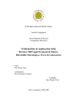
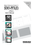
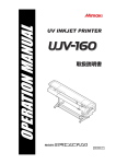
Supplement for the Basic Operation Manual 補足説明書 ENGLISH The following function is added from firmware version 2.20. Please read this manual and fully understand it before using the device. If you have any question, contact your local distributor. Correcting the dot positions ............................................................................2 This manual correspond to the models as firmware version 2.20 or later. When turning on the power, you can confirm the firmware version. 日本語 ファームウェア Ver.2.20 より、次の機能が追加になりました。 本書をお読みになり、十分理解してからご使用ください。 ご不明な点は、販売店または弊社営業所までご連絡ください。 ドット位置補正 ...................................................................................................7 本書は、ファームウェア Ver.2.20 以降の機種に対応しています。 ファームウェアのバージョンは、電源をオンにした際に確認できます。 MIMAKI ENGINEERING CO., LTD. D202087-10 Supplement for the Basic Operation manual Correcting the dot positions When plotting conditions (media thickness, head height, ink type or others) are changed, correct the dot positions during printing as follows to plot accurately. Before the operations below, plot the test pattern and check the nozzles are not clogged. If the nozzles are clogged, perform cleaning. (See the Operation Manual) When only “UNI-D” plotting is used, “Y Re.” and “Y Bi.” adjustment is not required. 1 Set media on the machine, and set a printing origin. • See the Operation Manual. • Use photopaper or others. • To print patterns, set the media to cover the effective plotting area on the table. 2 Press the key in the LOCAL mode. 3 Press the to select [MAINTENANCE]. 4 Press the 5 Press the 6 Press the 7 Press the 2 < EN T > MA I N T ENANCE S T A T I ON <en t > MA I N T ENANCE PR I N T a d j u s t <en t > MA I N T ENANCE Ad j u s t :Y Bi . MA I N T ENANCE Ad j u s t :Y Si . key. to select [PRINTadjust]. key. to select [Y Si.]. • First, adjust the dot positions for plotting outward. 8 Press the FUNC T I ON MA I N T ENANCE key twice. PR I N T I NG P L E AS E WA I T Correcting the dot positions 9 Press the to correct dot positions of the MA I N T ENANCE PA T T ERN 1 pattern 1. := 1.0 • Set value: -8.0 to +8.0 • Select the position that meets the “base line” and the “adjustment line” on the test pattern. ←Plotting direction Pattern example 1 PATTERN 7 PATTERN 6 PATTERN 5 PATTERN 4 PATTERN 3 PATTERN14 PATTERN13 PATTERN12 PATTERN11 PATTERN10 PATTERN 2 PATTERN 1 Adjustment Line Base Line PATTERN 9 PATTERN 8 The base line and the adjustment line meets on the first line from “0” in the plus direction. In this case, set “+1”. ←Plotting direction Pattern example 2 PATTERN 7 PATTERN 6 PATTERN 5 Adjustment Line PATTERN 4 PATTERN 3 PATTERN 2 PATTERN 1 Base Line PATTERN14 PATTERN13 PATTERN12 PATTERN11 PATTERN10 PATTERN 9 PATTERN 8 The adjustment line is closest to the base line on the third and the fourth line from “0” in the plus direction. In this case, set “+3.5”. 10Press the key. 11As in Step 9, correct dot positions of the pattern 2 to 14, and press the key. 3 Supplement for the Basic Operation manual 12Press the to select [Y Re.]. • Next, adjust the dot positions for plotting homeward. 13Press the MA I N T ENANCE Ad j u s t : Y Re . key twice. PR I N T I NG P L E AS E WA I T 14Press the to correct dot positions of the MA I N T ENANCE PA T T ERN 1 pattern 1. • Set value: -8.0 to +8.0 • Select the position that meets the “base line” and the “adjustment line” on the test pattern. := 1.0 ←Plotting direction Pattern example 1 PATTERN 7 PATTERN 6 PATTERN 5 PATTERN 4 PATTERN 3 PATTERN14 PATTERN13 PATTERN12 PATTERN11 PATTERN10 PATTERN 2 PATTERN 1 Adjustment Line Base Line PATTERN 9 PATTERN 8 The base line and the adjustment line meets on the first line from “0” in the plus direction. In this case, set “+1”. ←Plotting direction Pattern example 2 PATTERN 7 PATTERN 6 PATTERN 5 Adjustment Line PATTERN 4 PATTERN 3 PATTERN 2 PATTERN 1 Base Line PATTERN14 PATTERN13 PATTERN12 PATTERN11 PATTERN10 PATTERN 9 PATTERN 8 The adjustment line is closest to the base line on the third and the fourth line from “0” in the plus direction. In this case, set “+3.5”. 15Press the key. 16As in Step 14, correct dot positions of the pattern 2 to 14, and press the key. 4 Correcting the dot positions 17Press the to select [Y Bi.]. MA I N T ENANCE Ad j u s t • Adjust the dot positions for plotting bi-directionally. 18Press the 19Press the :Y Bi . key twice. PR I N T I NG P L E AS E WA I T to correct dot positions of the MA I N T ENANCE PA T T ERN 1 pattern 1. := • Set value: -40.0 to +40.0 • Select the position that meets the “outward line” and the “homeward line” on the test pattern. • If any lines do not meet on the test pattern, adjust the head height, and correct dot positions again. -4.0 ←Plotting direction Pattern example PATTERN 1 Pattern 11 パターン Outward Line Pattern 2 Homeward Line Pattern 3 Pattern 4 _ - + ±0 The outward line and the homeward line meets on the fourth line from “0” in the minus direction. In this case, set “-4”. (A long line in the center of the pattern indicates “0”.) 20Press the key. 21As in Step 19, correct dot positions of the pattern 2 to 4, and press the key. 22Set a new media on the machine, and set a printing origin. 5 Supplement for the Basic Operation manual 23Press the to select [X DIR.]. MA I N T ENANCE Ad j u s t • Adjust the dot positions for X direction. 24Press the :X DIR. key twice. PR I N T I NG P L E AS E WA I T 25Press the to correct dot positions of the pattern 1. • Set value: -20.0 to +20.0 (unit: 1.0) • Select the position that meets the right and left line on the test pattern. MA I N T ENANCE PA T T ERN 1 := 2.0 ←Plotting direction Pattern example PATTERN 1 PATTERN 2 PATTERN 3 PATTERN 1 The right and left line meets on the second line from “0” in the plus direction. In this case, set “+2”. (A long line in the center of the pattern indicates “0”.) 26Press the key. 27As in Step 25, correct dot positions of the pattern 2 to 3, and press the key. 28Press the 6 key several times to finish the correction. ド ッ ト 位置補正 ド ッ ト 位置補正 プ リ ン ト 時の条件 ( メ デ ィ ア の厚み/ヘ ッ ド の高 さ / イ ン ク の種類な ど ) が変わ っ た と き は、 次の操作を し て プ リ ン ト 時の イ ン ク の落下位置を補正 し 、 適正な プ リ ン ト 結果を得 ら れ る よ う に し て く だ さ い。 • 以下の操作の前に テ ス ト 作図を行い、 ノ ズル詰ま り が無い こ と を確認 し て く だ さ い。 ノ ズル詰ま り が あ る 場合は、 ク リ ーニ ン グ を行 っ て く だ さ い。 (取扱説明書を参照 し て く だ さ い) • 単方向印刷のみ を使用 し て い る 場合は、 [Y フ ク ロ ] お よ び [Y オ ウ フ ク ] の調整は不要で す。 1 メ デ ィ ア を セ ッ ト し 、 プ リ ン ト 原点を設定す る • 取扱説明書を参照してください。 • メディアは、 フォトペーパー等を使用してください。 • パターンプリントをするには、 テーブル面の有効作図エリアを覆うようにメディアをセットしてください。 2 ロ ー カ ルモー ド で 3 4 5 6 7 キー を押す を押 し て、 [ メ ン テナ ン ス ] を選ぶ キー を押す を押 し て、 [ ド ッ ト イ チホ セ イ ] を選ぶ キー を押す を押 し て、 [Y オ ウ ロ ] を選ぶ • まず、 往路で印刷する場合のインクの着弾位置を調整します。 8 キー を 2 回押す FUNCTION メンテナンス <ENT> メンテナンス ステーション メンテ < e n t > メンテナンス ト゛ットイチ ホセイ < e n t > メンテナンス ホセイ : Y オウフク メンテナンス ホセイ : Y オウロ サクス゛ チュウ シハ゛ラク オマチクタ゛サイ 7 補足説明書 9 を押 し て、 パ タ ー ン 1 の ド ッ ト 位置を補正す る メンテナンス ハ゜ターン1 • 設定値 : -8.0 ~ +8.0 • テストパターンの 「基準線」 と 「調整線」 が一致している位置を選択します。 パターン出力例 1 := 1.0 ←印刷方向 調整線 基準線 “0” からプラス方向に 1 本目で、 基準線と調整線が一致しています。 この場合、 設定値を 「+1」 にしてください。 パターン出力例 2 ←印刷方向 調整線 基準線 “0” からプラス方向の 3、 4 本目で、 基準線と調整線が最も接近しています。 この場合、 設定値を 「+3.5」 にしてください。 10 キー を押す 11手順 9 と 同様に し て、 パ タ ー ン 2 ~ 14 の ド ッ ト 位置を補正 し 、 8 キー を押す ド ッ ト 位置補正 12 を押 し て、 [Y フ ク ロ ] を選ぶ 13 14 メンテナンス ホセイ • 次に、 復路で印刷する場合のインクの着弾位置を調整します。 キー を 2 回押す : Y フクロ サクス゛ チュウ シハ゛ラク オマチクタ゛サイ を押 し て、 パ タ ー ン 1 の ド ッ ト 位置を補正す る メンテナンス ハ゜ターン1 • 設定値 : -8.0 ~ +8.0 • テストパターンの 「基準線」 と 「調整線」 が一致している位置を選択します。 パターン出力例 1 := 1.0 ←印刷方向 調整線 基準線 パターン出力例 2 調整線 ←印刷方向 “0” からプラス方向に 1 本目で、 基準線と調整線が一致しています。 この場合、 設定値を 「+1」 にしてください。 基準線 “0” からプラス方向の 3、 4 本目で、 基準線と調整線が最も接近しています。 この場合、 設定値を 「+3.5」 にしてください。 15 キー を押す 16手順 14 と 同様に し て、 パ タ ー ン 2 ~ 14 の ド ッ ト 位置を補正 し 、 キー を押す 9 補足説明書 17 を押 し て、 [Y オ ウ フ ク ] を選ぶ 18 19 メンテナンス ホセイ • 双方向で印刷したときの着弾位置を調整します。 キー を 2 回押す : Y オウフク サクス゛ チュウ シハ゛ラク オマチクタ゛サイ を押 し て、 パ タ ー ン 1 の ド ッ ト 位置を補正す る メンテナンス • 設定値 : -40.0 ~ +40.0 ハ゜ターン1 := -4.0 • テストパターンの 「往路」 と 「復路」 が一致している位置を選択します。 • テストパターンを確認しても、 線が一致する箇所がない場合は、 ヘッドの高さを調整し直してから、 再度、 ドット位置 補正をしてください。 ←印刷方向 パターン出力例 パターン 1 往路 パターン 2 復路 パターン 3 パターン 4 _ - + ±0 “0” からマイナス向に 4 本目で、 左右の線が一致しています。 この場合、 設定値を 「-4」 にしてください。 (中央の長い線の位置が 0 を示します) 20 キー を押す 21手順 19 と 同様に し て、 パ タ ー ン 2 ~ 4 の ド ッ ト 位置を補正 し 、 22新 し い メ デ ィ ア を セ ッ ト し 、 プ リ ン ト 原点を設定す る 10 キー を押す ド ッ ト 位置補正 23 24 25 を押 し て、 [X ホ ウ コ ウ ] を選ぶ • X 方向の着弾位置を調整します。 キー を 2 回押す メンテナンス ホセイ : X ホウコウ サクス゛ チュウ シハ゛ラク オマチクタ゛サイ を押 し て、 パ タ ー ン 1 の ド ッ ト 位置を補正す る • 設定値 : -20.0 ~ +20.0 (1.0 単位) • テストパターンの左右の線が一致している位置を選択します。 メンテナンス ハ゜ターン1 := 2.0 ←印刷方向 パターン出力例 “0” からプラス方向に 2 本目で、 左右の線が一致しています。 この場合、 設定値を 「+2」 にしてください。 (中央の長い線の位置が 0 を示します) 26 キー を押す 27手順 25 と 同様に し て、 パ タ ー ン 2、 3 の ド ッ ト 位置を補正 し 、 28補正を終わ る と き、 キー を押す キー を数回押す 11 D202087-10-08072009 All Rights Reserved. © MIMAKI ENGINEERING CO., LTD. EM FW:2.20