1
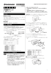
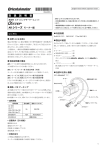
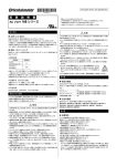
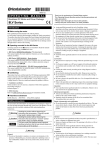
HG-9018-3 お買い上げいただきありがとうございます。 この取扱説明書には、製品の取り扱いかたや安全上の注意事項を示して います。 • 取扱説明書をよくお読みになり、製品を安全にお使いください。 取 扱 説 明 書 平行軸ギヤヘッド (GFS タイプ) • お読みになったあとは、いつでも見られるところに必ず保管してくださ い。 English version follows Japanese version. 表 2<取付穴参考寸法>(単位:mm) はじめに お使いになる前に 製品の取り扱いは、適切な資格を有する人が行なってください。お使いにな る前に、本書をよくお読みのうえ、正しくお使いください。 製品内部の点検や修理が必要なときは、お買い上げになった支店・営業所 にご連絡ください。 ØA 70 94 104 120 品 名 GFS2G GFS4G GFS5G GFS6G ØB 24 34 40 42 C 10 13 18 20 4×ØD 4.5 6.5 8.5 8.5 ∗ 品名中の には、ギヤヘッドの減速比を表わす数字が入ります。 <取付穴参考寸法図> 有害物質 4×ØD RoHS(EU 指令 2002/95/EC 27Jan.2003)適合 ØB モーターとギヤヘッドの品名を確認してください。下記のように、型番と歯切 りタイプの両方が同じものだけが接続できます。 • 䊝䊷䉺䊷䈱ຠฬ • 䉩䊟䊓䉾䊄䈱ຠฬ 䋼䋾㩷BLF 5 120A- GFS GFS 5 G20 ∗ ØB は製品外形寸法です。穴あけは ØB の 寸法+1 mm 以上の寸法で加工してくださ い。 C 品名・付属品の確認 ØA ဳ⇟ モーターとギヤヘッドの組み付け ᱤಾ䉍䉺䉟䊒 ギヤヘッド本体の他に以下を付属しています。ご確認ください。 モーターとギヤヘッドの組み付けは、図のようにそれぞれのインロー部を案 内として、モーター出力軸歯切り部をギヤヘッド側板やギヤに強く当てない よう、ギヤヘッドを静かに左右に回しながら行なってください。このとき、モー ターフランジ面とギヤヘッドインロー端面にすきまがないことを確認してくだ さい。 モーターケーブルの位置は、90º単位で変えられます。 モーターとギヤヘッドを組み付けた後、付属のモーター・ギヤヘッド組付用 ボルトで固定すると、装置への取り付け作業が簡単になります。 付属品 • 取付用六角穴付ボルトセット ボルト、六角ナット、平ワッシャ、バネ座金 .....各 4 個 • モーター・ギヤヘッド組付用ボルト .................2 個 GFS2G /GFS4G ....................................M2.6 六角穴付ボルト GFS5G /GFS6G ....................................M3 六角穴付ボルト • 平行キー ..........................................................1 個 (GFS6G タイプはギヤヘッド出力軸に固定してあります) 重要 0 6+ 0.040 6- 0.03 0 25±0.2 0 5+ 0.040 5- 0.03 0 GFS6G䂔䉺䉟䊒 • モーターとギヤヘッドを無理に組み付けたり、ギヤヘッドに金属 片などの異物が混入すると、モーター出力軸歯切り部やギヤ に傷が付き、異常音発生や寿命の低下など、思わぬ事故の原 因となります。ご注意ください。 • モーターインロー部、O リング、およびギヤヘッドインロー部に ゴミなどの異物を付着させないでください。また、ギヤヘッドと モーターを組み付けるときは、O リングを噛み込まないようにし てください。O リングをつぶしたり切断すると、ギヤヘッド内のグ リース漏れの原因になります。 䊐䊤䊮䉳㕙 24.5 32±0.2 䉟䊮䊨䊷ㇱ┵㕙 0 6- 0.03 25±0.2 0 6- 0.03 GFS5G䂔䉺䉟䊒 GFS4G䂔䉺䉟䊒 3+ 0.1 0 4+ 0.040 0 0 5- 0.03 0 4- 0.03 3.5+ 0.1 0 25±0.2 0 4- 0.03 GFS2G䂔䉺䉟䊒 2.5+ 0.1 0 キー・キーみぞ寸法図(単位:mm) 䊝䊷䉺䊷䊶䉩䊟䊓䉾䊄 ⚵ઃ↪䊗䊦䊃 䊝䊷䉺䊷 表 1<取付用六角穴付ボルト寸法> 品 名 GFS2G5~20 GFS2G30~100 GFS2G200 GFS4G5~20 GFS4G30~100 GFS4G200 GFS5G5~20 GFS5G30~100 GFS5G200 GFS6G5~20 GFS6G30、50 GFS6G100、200 呼び×首下長さ(mm) M4 P0.7×50 M4 P0.7×55 M4 P0.7×60 M6 P1.0×65 M6 P1.0×70 M6 P1.0×75 M8 P1.25×75 M8 P1.25×90 M8 P1.25×95 M8 P1.25×95 M8 P1.25×110 M8 P1.25×120 O䊥䊮䉫 䉩䊟䊓䉾䊄 䉟䊮䊨䊷ㇱ 品 名 GFS2G GFS4G GFS5G GFS6G 䊝䊷䉺䊷ജゲ ᱤಾ䉍ㇱ ボルトの呼び 締付トルク M2.6 0.4 N·m M3 0.6 N·m ∗ 品名中の には、ギヤヘッドの減速比を表わす数字が入ります。 • ギヤヘッド出力軸回転方向 装置への取り付け 付属の取付用六角穴付ボルトセットを使用し、取り付けてください。 䊝䊷䉺䊷 䊅䉾䊃 減速比 品 名 ขઃ᧼ 䉴䊒䊥䊮䉫䊪䉾䉲䊞 ギヤヘッドの種類により、モーターの回転方向とギヤヘッド出力軸の回転方 向が異なる組み合わせがあります。ご希望のギヤヘッド出力軸の回転方向 に合わせ、モーターの回転方向を決めて結線してください。 ᐔ䊪䉾䉲䊞 ขઃ↪ⷺⓣઃ䊗䊦䊃 䉩䊟䊓䉾䊄 GFS2G GFS4G GFS5G GFS6G モーターと同方向 モーターと逆方向 5~20、200 30~100 5~20、100、200 30、50 ∗ 品名中の には、ギヤヘッドの減速比を表わす数字が入ります。 • 最大許容トルク 品 名 GFS2G GFS4G GFS5G GFS6G ボルトの呼び M4 M6 締付トルク 1.8 N·m 6.4 N·m 適用最大板厚∗(mm)t 5 8 M8 15.5 N·m 12 ∗ 適用最大板厚は、付属の取付用六角穴付ボルトセットを使用した場合です。 品名中の には、ギヤヘッドの減速比を表わす数字が入ります。 • 許容オーバーハング荷重と許容スラスト荷重 負荷の取り付け ギヤヘッド出力軸は外径公差を h7 に仕上げ、伝達部品取り付けのための キーみぞ加工をしています。伝達部品を取り付ける場合は、出力軸と伝達 部品のはめ合いをすきまばめにしてください。さらに伝達部品のがたつきを 防止するため、ねじで固定してください。 䊝䊷䉺䊷 ࿕ቯ䈰䈛 ∗ GFS6G タイプの場合、 平行キーは出力軸に固定 してあります。 ᐔⴕ䉨䊷 オーバーハング荷重とは、図に示すように、ギ ヤヘッド出力軸に直角方向にかかる荷重です。 スラスト荷重とは、出力軸の軸方向にかかる荷 重です。オーバーハング荷重とスラスト荷重は、 軸受の寿命や軸の強度に大きく影響を与えま すので、表 3 の許容オーバーハング荷重、許容 スラスト荷重を超えないようにご注意ください。 出力軸先端ねじ穴は、伝達部品の抜け防止の補助として使用してください。 (GFS2G タイプには、出力軸先端ねじ穴はありません。) GFS2G <出力軸先端ねじ穴使用例> વ㆐ㇱຠ GFS4G ࿕ቯ䈰䈛 䉴䊕䊷䉰 GFS5G GFS6G 䈰䈛 品 名 GFS4G GFS5G GFS6G 出力軸先端ねじ穴 M5 有効深さ 10 mm M6 有効深さ 12 mm ∗ 品名中の には、ギヤヘッドの減速比を表わす数字が入ります。 重要 䉥䊷䊋䊷䊊䊮䉫⩄㊀ 䉩䊟䊓䉾䊄 䉴䊤䉴䊃⩄㊀ 表 3<許容オーバーハング荷重と許容スラスト荷重> 品 名 䉩䊟䊓䉾䊄 વ㆐ㇱຠ ギヤヘッドの出力トルクは減速比が大きくなると、それに比例して大きくなり ますが、歯車の材質、その他の条件によりギヤヘッドにかけられる負荷トル クの大きさが限定されます。これを最大許容トルクとして、ギヤヘッドの大きさ、 減速比により規定しています。各減速比に応じた許容トルク内でお使いくだ さい。詳しくは、カタログをご覧ください。また、当て止めは絶対にしないでく ださい。当て止めすると、その衝撃によりギヤヘッドが壊れてしまうおそれが あります。 減速比 最大許容 トルク N·m 5 10~20 30~200 5 10~20 30~200 5 10~20 30~200 5~20 30、50 100、200 6 (5.4) 16 (14) 30 (27) 70 (63) 許容オーバー ハング荷重 N 出力軸先端から 10 mm 20 mm 100(90) 150(110) 150(130) 200(170) 200(180) 300(230) 200(180) 250(220) 300(270) 350(330) 450(420) 550(500) 300(230) 400(300) 400(370) 500(430) 500(450) 650(550) 550(500) 800(700) 100(900) 1250(1100) 1400(1200) 1700(1400) 許容 スラスト 荷重 N 40 (40) 100 (100) 150 (150) 200(200) 300(300) 400(400) ∗ モーター軸回転速度 3000 r/min 時の値です。( )は 4000 r/min 時の値です。 品名中の には、ギヤヘッドの減速比を表わす数字が入ります。 • この取扱説明書の一部または全部を無断で転載、複製することは、禁止 されています。 • 取扱説明書に記載されている情報、回路、機器、および装置の利用に関 して産業財産権上の問題が生じても、当社は一切の責任を負いません。 ハンマー等で無理に挿入すると、軸受の破損の • 製品の性能、仕様および外観は改良のため予告なく変更することがあり 原因になります。出力軸に無理な力を加えない でください。 • 取扱説明書には正確な情報を記載するよう努めていますが、万一ご不審 使用上のご注意 ますのでご了承ください。 な点や誤り、記載もれなどにお気づきの点がありましたら、最寄りのお客 様ご相談センターまでご連絡ください。 • は、日本その他の国におけるオリエンタルモーター株 式会社の登録商標または商標です。 • 使用周囲温度範囲-10~+50 °C、湿度 85%以下の場所でお使いください。 • 直射日光があたる所や、水や油のかかる所は避けてください。 • 振動、衝撃の激しい所や、埃の多い所、引火性ガス、腐食性ガスの発生 © Copyright ORIENTAL MOTOR CO., LTD. 2008 する所は避けてください。 • ギヤヘッドからまれに少量のグリースがにじみ出ることがあります。グリー ス漏れによる周囲環境の汚染が問題となる場合には、定期点検時にグ リースのにじみをチェックしてください。または、油受けなどの損害防止装 置を取り付けてください。油漏れでお客様の装置や製品等に不具合を発 生させる原因になります。 䃂㩷ຠ䈮䈧䈇䈩䈱䈗⾰䇮䈗⋧⺣䈲䈍ቴ᭽䈗⋧⺣䉶䊮䉺䊷䈻䈍䈇ว䉒䈞䈒䈣䈘䈇䇯 㩷㩷㩷㩷䊐䊥䊷䉮䊷䊦䋨ήᢱ䋩䈪䈜䇯៤Ꮺ㔚䊶PHS䈎䉌䉅䈗↪䈏น⢻䈪䈜䇯 ฃઃᤨ㑆㩷 ᐔᣣ㩷 9:00䌾18:30 㩷 ᦐᣣ㩷 9:00䌾17:30 http://www.orientalmotor.co.jp/ ᧲㩷 ੩㩷 TEL 0120-925-410 ฬฎደ㩷 TEL 0120-925-420 ᄢ㩷 㒋㩷 TEL 0120-925-430 FAX 0120-925-601 FAX 0120-925-602 FAX 0120-925-603 䈖䈱ขᛒ⺑ᦠ䈲ౣ↢⚕䉕↪䈚䈩䈇䉁䈜䇯 HG-9018-3 OPERATING MANUAL Thank you for purchasing an Oriental Motor product. This Operating Manual describes product handling procedures and safety precautions. ・Please read it thoroughly to ensure safe operation. ・Always keep the manual where it is readily available. Gearhead (GFS Types) Before using the gearhead Table 1. Size of hexagonal socket head bolts Introduction Only qualified personnel should work with the product. To ensure correct operation, please read this manual carefully before using your gear head. Should you require the inspection or repair of internal parts, contact the Oriental Motor office where you purchased the product. Hazardous substances RoHS (Directive 2002/95/EC 27Jan.2003) compliant Verifying the product name and accessories Check the model names of the motor and gearhead. Gearheads and motors will fit together only if they are both of the same frame size (first digit of model name is the same) and of the same gear type. • Motor model • Gearhead model Example: BLF 5 120A- GFS GFS 5 G20 Frame size Gear type series Gearhead comes with following accessories for mounting the motor and gearhead on equipment. Also check them completely provided. Accessories • Hexagonal socket head screw, Hexagon nuts, Washers, Spring washers ........................................4 pcs. each • Motor-gearhead assembly bolts..............................2 pcs. GFS2G /GFS4G ..............................................M2.6 Hex-bolts GFS5G /GFS6G ..............................................M3 Hex-bolts • Key ..........................................................................1 pc. (For GFS6G type, a key is fixed on the gearhead’s shaft.) Gearhead model name GFS2G5 to 20 GFS2G30 to 100 GFS2G200 GFS4G5 to 20 GFS4G30 to 100 GFS4G200 GFS5G5 to 20 GFS5G30 to 100 GFS5G200 GFS6G5 to 20 GFS6G30, 50 GFS6G100, 200 Thread series×length [mm (inch)] M4 P0.7×50 (1.97) M4 P0.7×55 (2.17) M4 P0.7×60 (2.36) M6 P1.0×65 (2.56) M6 P1.0×70 (2.76) M6 P1.0×75 (2.95) M8 P1.25×75 (2.95) M8 P1.25×90 (3.54) M8 P1.25×95 (3.74) M8 P1.25×95 (3.74) M8 P1.25×110 (4.33) M8 P1.25×120 (4.72) Table 2. Installation hole dimensions [mm (inch)] Gearhead model name GFS2G GFS4G GFS5G GFS6G ØA ØB C 4×ØD 70 (2.76) 94 (3.70) 104 (4.09) 120 (4.72) 24 (0.94) 34 (1.34) 40 (1.57) 42 (1.65) 10 (0.39) 13 (0.51) 18 (0.71) 20 (0.79) 4.5 (0.177) 6.5 (0.256) 8.5 (0.335) 8.5 (0.335) ∗ The square box in the gearhead model will contain a value representing the gear ratio. <Installation holes> 4×ØD ØB C ∗ ØB indicates the external dimension of the product. Provide a hole with a diameter of "ØB +1 mm (0.04 inch) or more." ØA GFS5G type 25±0.2 (0.984±0.008) (0.1575+ 00.0016 ) 0 5- 0.03 5+ 0.040 0 0 (0.1969- 0.0012 ) (0.1969+ 00.0016 ) 0 6- 0.03 6+ 00.040 0 (0.2362- 0.0012 ) (0.2362+ 00.0016 ) 2.5+ 0.1 0 (0.098+ 00.004 ) 4+ 0.040 0 0 (0.1575- 0.0012 ) 3+ 0.1 0 (0.118+ 00.004 ) 25±0.2 (0.984±0.008) 0 4- 0.03 3.5+ 0.1 0 (0.138+ 00.004 ) GFS4G type 0 5- 0.03 0 (0.1969- 0.0012 ) 25±0.2 (0.984±0.008) 0 6- 0.03 0 (0.2362- 0.0012 ) GFS2G type 0 4- 0.03 0 (0.1575- 0.0012 ) Key and key slot dimensions [Unit = mm (inch)] Connecting gearhead to motor Align the gearhead and motor as in the Figure below, then engage the pinion section of the shaft to the gear gently by turning the gearhead slightly in both directions until the gearhead and motor fit flush together. The position of the motor cable can be changed in increments of 90°. Two assembly screws are provided to make installation easier. First mount gearhead to motor with assembly bolts. Next motor and gearhead assembly to your application with hex-bolts. Note • Forcing the motor and gearhead together during assemble or permitting contamination by foreign matter inside the gearhead will cause excess noise and/or shorter life of the gearhead. • Remove any particles of dust or other waste that may be clinging to the O-ring or the pilot section of the motor or gearhead. Do not pinch the O-ring when assembling the motor and gearhead. Pinching or cutting the O-ring causes a grease leak from the gearhead. Flange Mating surface Motor-gearhead assembly bolt 32±0.2 (1.260±0.008) 0 6- 0.03 GFS6G type 0 (0.2362- 0.0012 ) Motor 24.5 (0.96) Gearhead Gearhead model name GFS2G□, GFS4G□ GFS5G□, GFS6G□ O-ring Output shaft of motor Pilot section Nominal diameter of bolts M2.6 M3 Tightening torque 0.4 N·m (3.5 lb-in) 0.6 N·m (5.3 lb-in) ∗ The square box in the gearhead model will contain a value representing the gear ratio. Installing gearmotor Use the mounting bolts provided with the gearhead to mount the gearhead and motor on equipment. Motor Washer Spring washer Mounting plate Hexagonal socket head bolt Gearhead GFS2G GFS4G GFS5G GFS6G Nominal Maximum thickness of Tightening torque diameter of mounting plate∗ [N·m (lb-in)] bolts t [mm (inch)] M4 1.8 (15.9) 5 (0.20) M6 6.4 (56) 8 (0.31) M8 15.5 (137) 12 (0.47) ∗ When using provided bolts. The square box in the gearhead model will contain a value representing the gear ratio. Attaching load The shaft of the gearhead has been machined to an outer diameter tolerance of h7 and is provided with a key slot for connecting the transmission parts. When connecting the transmission parts, ensure that the shaft and parts have a clearance fit, and secure with a screw to prevent the parts from wobbling. Motor Fixed screw ∗ For GFS6G type, a key is fixed on the gearhead’s shaft. Key Gearhead Transmission parts Transmission parts 30 to 100 5 to 20, 100, 200 30, 50 Table 3. Permissible Overhung Load and Thrust Load Gearhead model name GFS2G GFS5G GFS6G Fixed screw Spacer Gear ratio 5 10 to 20 30 to 200 5 10 to 20 30 to 200 5 10 to 20 30 to 200 5 to 20 30, 50 100, 200 Maximum permissible torque N·m 6 (5.4) 16 (14) 30 (27) 70 (63) Permissible overhung Permissible load N thrust load From the end of shaft N 10 mm 20 mm 100 (90) 150 (110) 40 150 (130) 200 (170) (40) 200 (180) 300 (230) 200 (180) 250 (220) 100 300 (270) 350 (330) (100) 450 (420) 550 (500) 300 (230) 400 (300) 150 400 (370) 500 (430) (150) 500 (450) 650 (550) 550 (500) 800 (700) 200 (200) 1000 (900) 1250 (1100) 300 (300) 1400 (1200) 1700 (1400) 400 (400) ∗ The values are at a motor shaft speed of 3000 r/min. Those in ( ) are at a motor shaft speed of 4000 r/min. The square box in the gearhead model will contain a value representing the gear ratio. Screw • • M5 Output shaft tip screw hole Effective depth 10 mm (0.39 inch) M6 Effective depth 12 mm (0.47 inch) ∗ The square box in the gearhead model will contain a value representing the gear ratio. Note 5 to 20, 200 • Maximum Permissible Torque Since the output torque of the gearhead increases proportionally with the reduction of speed, a high reduction ratio of the gearhead will result in an output torque that cannot be taken up by the physical construction of the gearhead. Use gearheads within the maximum permissible torque set for each speed reduction ratio. For the values of the maximum permissible torque, please refer to catalogue. Also, be sure shaft rotation is not stopped by an external force or load obstruction. The resulting shock may damage the gearhead. • Permissible Overhung Load and Permissible Thrust Load “Overhung load” refers to load placed on the output Overhung load shaft of the gearhead in a direction perpendicular to Gearhead the shaft as shown to the right. The “Thrust load” is a load applied in the axial direction of the output shaft. Since the overhung load and thrust load have a great Thrust load influence on the life of the bearings and strength of the shaft, be careful not to exceed the maximum values shown in the Table 3. GFS4G Use a screw hole provided at the tip of the output shaft as an auxiliary means for preventing the transfer mechanism from disengaging.(GFS2G type have no output shaft tip screw hole.) <The example of output shaft tip screw hole use.> Gearhead model name GFS4G GFS5G GFS6G Gear ratio Same direction as motor Opposite direction to motor ∗ The square box in the gearhead model will contain a value representing the gear ratio. Nut Gearhead model name Gearhead model name GFS2G GFS4G GFS5G GFS6G Do not use excessive force, or hammer the transmission parts onto the gearmotor shaft as damage may occur. Precautions for Operation • Use your gearmotor under ambient temperature of -10 to +50 °C (+14 to +122 ºF) and 85% humidity. • Do not use your gearmotor where it may be exposed direct sunlight water and/ or oil. • Do not use your gearmotor in locations subject to severe vibration or shock, a large amount of dust, inflammable gas and or corrosive gas. • On rare occasions, a small amount of grease may ooze out from the gearhead. If there is concern over possible environmental damage resulting from the leakage of grease, check for grease stains during regular inspections. Alternatively, install an oil pan or other device to prevent leakage from causing further damage. Oil leakage may lead to problems in the customer’s equipment or products. • Direction of Rotation of the Gearhead Output Shaft With some gear ratios, the motor and gearhead output shaft will rotates in opposite directions. • • Unauthorized reproduction or copying of all or part of this manual is prohibited. Oriental Motor shall not be liable whatsoever for any problems relating to industrial property rights arising from use of any information, circuit, equipment or device provided or referenced in this manual. Characteristics, specifications and dimensions are subject to change without notice. While we make every effort to offer accurate information in the manual, we welcome your input. Should you find unclear descriptions, errors or omissions, please contact the nearest office. • is a registered trademark or trademark of Oriental Motor Co., Ltd., in Japan and other countries. © Copyright ORIENTAL MOTOR CO., LTD. 2008 • Please contact your nearest Oriental Motor office for further information. Technical Support Tel:(800)468-3982 8:30 A.M. to 5:00 P.M., P.S.T. (M-F) 7:30 A.M. to 5:00 P.M., C.S.T. (M-F) E-mail: [email protected] www.orientalmotor.com Headquarters and Düsseldorf Office Munich Office Hamburg Office Tel:0211-52067-00 Tel:089-3181225-00 Tel:040-76910443 Fax:0211-52067-099 Fax:089-3181225-25 Fax:040-76910445 Tel:01256-347090 Fax:01256-347099 Tel:01 47 86 97 50 Fax:01 47 82 45 16 Tel:02-93906346 Fax:02-93906348 Tel:(02)8228-0707 Fax:(02)8228-0708 Tel:(6745)7344 Fax:(6745)9405 Tel:(03)22875778 Fax:(03)22875528 Tel:66-2-254-6113 Fax:66-2-254-6114 KOREA Tel:(032)822-2042~3 Fax:(032)819-8745 Headquarters Tokyo, Japan Tel:(03)3835-0684 Fax:(03)3835-1890 Printed on Recycled Paper