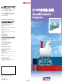
1
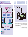
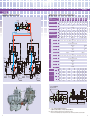
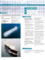
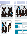
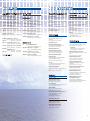
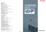
本 社 ・ 工 場 神戸市西区櫨谷町松本234番地
Tel.(078)991-1133
〒651-2239
Fax.(078)991-3186
東 京 支 社 東京都港区浜松町2丁目4-1(世界貿易センタービル) 〒105-6116
Tel.(03)3435-6862
Fax.(03)3435-2023
神 戸 支 社 神戸市中央区東川崎町1丁目1-3(神戸クリスタルタワー) 〒650-8680
Tel.(078)360-8608
Fax.(078)360-8609
http://www.khi.co.jp/kpm/
KAWASAKI PRECISION MACHINERY NETWORK
Head Office / Main Plant
234, Matsumoto, Hasetani-cho, Nishi-ku, Kobe 651-2239, Japan
Phone: 81-78-991-1133 Fax: 81-78-991-3186
Tokyo Office
World Trade Center Bldg., 4-1, Hamamatsu-cho 2-chome, Minato-ku, Tokyo
105-6116, Japan
Phone: 81-3-3435-6862 Fax: 81-3-3435-2023
Kobe Office
Kobe Crystal Tower, 1-3, Higashikawasaki-cho 1-chome, Chuo-ku, Kobe,
650-8680, Japan
Phone: 81-78-360-8608 Fax: 81-78-360-8609
http://www.khi.co.jp/kpm/
OVERSEAS SUBSIDIARIES
Kawasaki Precision Machinery (UK) Ltd.
Ernesettle Lane, Ernesettle, Plymouth, Devon PL5 2SA, United Kingdom
Phone: 44-1752-364394 Fax: 44-1752-364816
http://www.kpm-eu.com
Kawasaki Precision Machinery (U.S.A.), Inc.
5080, 36th Street S.E. Grand Rapids, Michigan 49512 U.S.A.
Phone: 1-616-949-6500 Fax: 1-616-975-3103
http://www.kawasakipmd.com
Kawasaki Precision Machinery (China) Ltd.
9 Guanshan Rd., New District, Suzhou, 215151 China
Phone: 86-512-6616-0365 Fax: 86-512-6616-0366
Kawasaki Precision Machinery (China) Ltd.
Shanghai Branch Office
10th Floor, Chong Hing Finance Center 288 Nanjing Road West, Huangpu
District, Shanghai 200003, China
Phone: 86-021-3366-3800 Fax: 86-021-3366-3808
Flutek, Ltd.
192-11, Shinchon-dong, Changwon, Kyungnam, 641-370 Korea
Phone: 82-55-286-5551 Fax: 82-55-286-5553
KK Hydraulics Sales (Shanghai) Ltd.
B-908 Far East International Plaza 317 Xianxia Rd, Shanghai 200051, China
Phone: 86-21-6235-1606 Fax: 86-21-6295-7080
● このカタログに記載の内容は、
改良のため予告なく改訂・変更する場合があります。
● Materials
and specifications are subject to change without manufacturer's obligation.
このカタログは再生紙を使用しています。
This catalog is printed on recycled paper.
Cat. No KPM0571 Jan.○
S
P rinted in Japan.
安全上の注意事項
納入実績16,000隻の技術が生きる
最新鋭の電動油圧舵取機
関連法規についての注意
本カタログの製品を安全にご使用いただくために、
下記「製品使用についての注意」や、
当該製品の取扱説明書を十分にご理解いただくとともに、
関連規格の安全に関する法規類を必ず遵守の上、
お取扱いください。
製品使用についての注意
(1)製品を取り扱う時の注意事項
製品を取り扱う際にけがをすることがありま
すので、状況に応じて保護具を着用してく
ださい。
製品の重量、作業姿勢によっては、手を挟
んだり腰を痛めたりすることがありますので、
作業方法に十分注意してください。
製品に乗ったり、叩いたり、落としたり、外力
を加えたりしないでください。作動不良、破損、
油漏れなどを起こすことがあります。やむを
得ず製品に乗る必要が生じた場合は、安全
に十分に注意いただくと共に製品の健全
性にも留意ください。
製品や床に付着した作動油は十分にふき取っ
てください。製品を落としたり、すべってけが
をする恐れがあります。
アルコール飲料や薬物を飲まれた後には、
作業を行なわないでください。
(2)製品の取り付け、取り外し時の注意事項
電気配線工事は必ず電源を切ってから行なっ
てください。感電する恐れがあります。
作業を行なう際には必ず装置の電源を切り、
電動機、エンジン等が停止したことを確認
してください。また、油圧配管内の圧力が「0」
圧であることも確認してください。
取り付け、
取り外し、
配管、
配線などの作業は、
専門知識のある方が行なってください。
初めて装置を運転する場合は油圧回路、
電気配線が正しいこと、および締結部に緩
みがないことを確認した上で運転してください。
*専門知識のある方:油圧調整技能士2級
程度、
または当社のサービス研修を受け
た方。
製品はカタログ、図面、仕様書などに記載さ
れた仕様以外で使用しないでください。
取付穴、取付面を清浄な状態にしてください。
ボルトの締めつけ不良、
シール破損により、
破損、油漏れなどを起こす恐れがあります。
運転中、製品は油温やソレノイドの温度上
昇などにより高温になりますので、手や体が
触れないように注意してください。やけどの
恐れがあります。
製品を取り付ける時は必ず規定のボルトを
使用し、規定のトルクで締めつけてください。
規定外の取り付けをすると作動不良、破損、
油漏れを起こすことがありますので注意して
ください。
作動油は適正な物を使用し、汚染度も推奨
値で管理してください。作動不良、破損の恐
れがあります。
(4)保守・保管上の注意事項
(3)運転時の注意事項
お客様による製品の改造は、絶対にしない
でください。
爆発または燃焼する危険性のある雰囲気
の中では、対策を講じた製品以外は絶対に
使用しないでください。
製品は断りなく分解、組み直しをしないでく
ださい。定められた性能を発揮できず、故障
や事故の原因になります。やむを得ず分解、
組み直しをする場合は専門知識のある方が
行なってください。
ポンプやモータなどの回転軸の保護カバー
は必ず付けたままとし、手や衣類などの巻き
込みを防止してください。
製品を運搬、保管する場合は、周囲温度、
湿度など環境条件に注意し、
防塵、
防錆を保っ
てください。
異常(異音、油漏れ、煙など)が発生した場
合は直ちに運転を停止し、必要な処置を講
じてください。破損、火災、
けがなどの恐れが
あります。
製品を長期保管後に使用する場合には、
シー
ル類の交換を必要とする場合があります。
SAFETY PRECAUTIONS
Before you use the product, you MUST read the operation or operators manual and MUST fully understand how to use the product.
To use the product safely, you MUST carefully read all Warnings and Cautions in this manual. You MUST also observe the related
regulations and rules regarding safety.
Cautions related to operation
CAUTION
Use the safety equipment to avoid the
injury when you operate the product.
Pay enough attention on handling method
to avoid pinching hands or back problems
CAUTION that may be caused by heavy weight of the
product or handling posture.
Do not step on the product, hit it, drop it
or give strong outside force to it, as one of
CAUTION these actions may cause the failure of
work, damage or oil leakage. If it is
necessary by all means to step on the
product, pay enough attention to your
safety and be careful not to damage the
product.
Wipe the oil on the product or floor off
completely, as the oil creates slippery
CAUTION conditions that may result in dropping the
product or injuring.
CAUTION
Never operate the product after you have
alcoholic drink or drug.
Warnings and Cautions related to
installation and removal of the product
Turn off the power before starting wiring
or other works related to the electric
DANGER power, otherwise you may be stuck by an
electric shock.
Make it sure that the power of the
hydraulic power unit is turned off and that
WARNING the electric motor or engine has
completely stopped before starting
installation or removal. You must also
check the system pressure has dropped to
zero.
1
Installation, removal, plumbing, and wiring
must be done by the certified person.
CAUTION *CERTIFIED PERSON : a person who has
enough knowledge like a person who is
trained by Kawasaki’s hydraulic school.
Clean the threads and mounting surface
completely, otherwise you may experience
CAUTION damages or oil leakage caused by
insufficient tightening torque or broken
seal.
Use the specified bolts and keep the
specified tightening torque when you install
CAUTION the product. Usage of unauthorized bolts,
lack of torque or excess of torque may
create problems such as failure of work,
damage and oil leakage.
Warnings and Cautions for operation
Never use the product not equipped with
anti-explosion protection in the
DANGER circumstances of possible explosion or
combustion.
Never remove the protection cover over the
rotating part such as motor shaft and pump
WARNING shaft to avoid injuries caused by being
rolled fingers or cloths in.
Stop the operation immediately if you find
something wrong such as unusual noise, oil
WARNING leakage or smoke, and fix it properly. If you
continue operating, you may encounter
damage, fire or injury.
Make it sure that plumbing and wiring are
correct and all the connection is tightened
CAUTION correctly before you start operating,
especially if it is the first run.
Use the product under the specification
mentioned in the drawings and
Fresh line-up of
Kawasaki Electro-Hydraulic Steering Gears
Based on our rich experience
with over 16,000 ship sets ever produced.
カワサキプレシジョンマシナリ(KPM)は、1924
年に電動油圧舵取機の製作に取り組んで以来、80年
以上の間、国内のみならず世界各国の船主、造船所各
位のご愛顧、ご信頼を得て、小は50G.T.から、大は
500,000D.W.T.まで、16,000隻以上の各種船舶
に舵取機を納入しています。
この長い歴史と豊富な経験をもとに、
KPMは常に
市場の要求をいち早く採り入れ、船舶における省力化、
運航の安全に大きく貢献しています。
今後さらに、皆さま方のニーズにお応えしていける
ものと確信しています。
More than eighty years has passed since Kawasaki
Precision Machinery Ltd., began the manufacture of
electro-hydraulic steering gears in 1924. During this
period our products have gained high reputation
among shipbuilders not only in Japan but also in
many countries of the world, and we have supplied
more than 16,000 units of steering gears to various
types of ships ranging from 50 G.T. to 500,000
D.W.T. building on a long history and a rich
experience of our products Kawasaki quickly takes
in requirements of the market and makes a great
contribution for labor saving and safety navigation
of the ships.
We are sure that we can go on meeting your
various needs with our steering gears.
CAUTION specification sheet.
Keep your body off the product during the
operations as it may become hot and burn
CAUTION your body.
Use the proper hydraulic oil, and maintain
the contamination in the recommended
CAUTION level, otherwise it may not work or be
damaged.
Cautions related to maintenance
CAUTION
Never modify the product without approval
of Kawasaki.
Do not disassemble and assemble without
approval by Kawasaki. It may cause
CAUTION troubles and failure, or it may not work as
specified. If it is necessary by all means to
disassemble and assemble, it must be done
by an authorized person.
Keep the product from dust and rust by
paying attention to the surrounding
CAUTION temperature and humidity when you
transport or store the product.
CAUTION
Replacing the seals may be required if you
use the product after long time storage.
2
舵取機のシリーズ構成/Series Constitution of Steering Gears
舵取機は、下記のように3シリーズに分類されています。
265kN・m(27ton・m)以下の舵取機については、小型舵取機
カタログをご参照ください。
RM Type
M Series
FM Type
1 Ram 2 Cyl.
(Fork type tiller)
314~844 kN·m
(32~86 ton·m)
The electro-hydraulic steering gears are classified into three
series as listed. For steering gears of 265kN·m (27 ton·m)
and below, small type steering gear catalogue is referred to.
Fork type
Roller
F3
Ram pin
Hydraulic cylinder
形式表示/Type Indication
RV 2 1 - 0 8 6 - H - T 1 0 0
シリーズ記号:
Series symbol
FE Type
V Series
RV Type
2 Rams 4 Cyl.
(Fork type tiller)
520~9,810 kN·m
(53~1,000 ton·m)
Ram
Rudder stock
Tiller
V式舵取機のハイドロロックアラームに関する追加表示
Additional indication of hyd. lock alarm for V series
M……機械式ポンプ制御システム
Mechanical pump control system
E…… 電気式ポンプ制御システム
Electrical pump control system
(連続制御システム)
(Continuous control system)
V…… バルブ制御システム
Valve control system
(Rシリーズのみ)
(R series only)
RE Type
F1
T050…… 非常時トルク/定格トルク=50%(F型用)
Emergency torque / rated torque(For F series)
T100…… 非常時トルク/定格トルク=100%(R型用)
Emergency torque / rated torque(For R series)
制御システム:
Control system
F2
E Series
1万GT以上のタンカーに対する追加規定表示
Additional indication for tanker over 10,000GT
R……フォーク形、1ラム2シリンダ
Fork type, 1 Ram 2 Cylinders
F……フォーク形、2ラム4シリンダ
Fork type, 2 Rams 4 Cylinders
H……… 電油弁作動不良検出器付
With hyd. lock detector of sol. hyd. valve.
舵取機出力トルク:
Torque(ton・m)
032,036,045,051,063,070,086 ……R series
053,064,072,090,102,126,140,172,207,243
288,350,400,485,560,685,825,1000 …F series
常用ポンプユニット数:
Number of pump units for normal use
装備ポンプユニット数:
Number of equipped pump units
1……1 set
2……2 sets
1……1 set
2……2 sets
3……3 sets
Features
特 長
Mシリーズ
シリーズ
Eシリーズ
Vシリーズ
〔機械式ポンプ制御舵取機〕
〔電気式ポンプ制御舵取機〕
〔バルブ制御舵取機〕
説 明
操舵スタンドからの舵角命令により遠
隔制御装置のパワーユニット
(油圧ポ
ンプ・電動機・電磁切換弁・パワーシリ
ンダ・配管等より構成)が作動し、
リン
ク機構を介して可変容量形ポンプの
傾転角を機械的に制御する方式です。
操舵スタンドからの舵角偏差信号によっ
てトルクモータを駆動し、可変容量形
ポンプの傾転角を電気的に制御する
方式です。
操舵スタンドから与えられた舵角偏差
信号によって電磁切換弁を制御し、固
定容量形ポンプからの吐出油方向を
切換えて操舵する方式です。
1 品
Series
E Series
V Series
〔Electrical Pump Control S/G〕
〔Valve Control S/G〕
Description
The rudder command signal from the
steering stand operates the power unit
(comprising hydraulic pump, electric
motor, solenoid valve, power cylinder,
pipes etc.) of remote control system and
controls mechanically the stroke of
variable displacement type pump
through link mechanism.
The rudder angle deviation signal, the
difference between command signal
and the feed-back signal of actual
rudder angle, from steering stand
controls electrically the stroke of
variable displacement type pump
through torque motor.
The rudder angle deviation signal, the
difference between command signal
and the feed-back signal of actual
rudder angle, from steering stand
operates the solenoid valve and
controls the direction of oil from fixed
displacement pump.
耐久性、信頼性とも舵取機として高水準にあります。
1 Quality
The high durability and reliability are guaranteed as steering gear.
2 Lシリーズポンプの採用
高圧、長寿命Lシリーズ斜軸形アキシャルピストンポンプの採用により舵取機の高圧化および耐久性の増大が可能となりま
した。
2 Adoption of L series pump
The adoption of L series bent axis type axial piston pump of higher pressure and longer life has enabled the design of high
pressurized and durable steering gear.
3 静
油圧ポンプをオイルタンクに内蔵していますので、
より静かな運転が保たれます。
3 Quiet operation
Quiet operation is maintained since the hydraulic pump is installed in the oil tank.
電動機は無負荷で始動できるため、非常用発電機容量を小さくすることができます。
4 Unloading start of
electric motor
The capacity of emergency generator can be reduced since electric motor is always started with the pump in unloaded
condition.
質
か
な
運
転
4 電動機無負荷始動
多数の油圧機器をオイルタンクに装備して大幅なパイプレス化を図るとともに、
オイルタンクおよび電動機を油圧シリンダ上
に配置しており、
コンパクトな構成となっています。
5 コ ン パ クト な 配 置
電気信号によって油圧ポンプを制御 電気信号によって電磁切換弁を制御
するため、遠隔制御装置のパワーユニッ するため、遠隔制御装置のパワーユニッ
トが不要です。
トが不要です。
Simple and compact constitutions are gained since external pipings are minimized and oil thank and electric motor are installed
on the hydraulic cylinder.
5 Compact arrangement
工場内で実際の配管を使用して組立てて納入しますので、船内での据付性が向上します。
6 据
付
性
油圧ポンプ制御用の機械リンク装置および緩衝装置が不要なため、Mシリーズ
と比較してポンプ配置に自由度があります。
7 保
守
性
機側操舵はハンドル装置を手動操作
することによって行なわれます。
8 適
用
船
級
機側操舵はトルクモータに装備した油
圧ポンプ傾転ノブを手動操作すること
によって行なわれます。
主要船級に適用可能ですが、詳細はお問い合せください。
機側操舵は電磁切換弁のプッシュロッ
ドを手動操作することによって行なわ
れます。
The power unit of remote control system
is not required since the hydraulic pump
is controlled by electric signal.
The power unit of remote control system
is not required since the solenoid valve
is controlled by electric signal.
Steering gear is constructed with actual pipings in the factory, requiring only a simple installation work on the ship.
6 Installation
ラム・シリンダなどの主要部品のほか操縦、追求装置などについても堅牢な設計とし、安全性について充分配慮してあります。
また各ジョイント部には含油メタルなどを採用して保守性に配慮しています。
3
M Series
〔Mechanical Pump Control S/G〕
The pump unit can be placed in convenient position in the steering gear
compartment compared with M series since there is no mechanical linkage nor
buffer spring for controlling the hydraulic pump.
Follow-up mechanisms as well as main parts of ram, hydraulic cylinder etc. are especially of sturdy construction and full
consideration is given to safety. Each joint portion is provided with oil-less metal to facilitate maintenance.
7 Maintenance
The local steering can be performed by
trick wheel.
8
Applicable
classification society
The local steering can be performed by
pump control knob on torque motor.
The local steering can be performed by
pushing manually the push rod of
solenoid valve.
Please consult with us on this matter,
(Can be installed on the vessels classified in most classification societies.)
4
TYPE RM
◆油圧回路/HYDRAULIC CIRCUIT
◆主要目・外形寸法/PARTICULARS & DIMENSIONS
Type
Particulars
No.2 Cyl.
No.1 Cyl.
kN・m
t・m
Rule dia. in way of rudder head mm
deg
Rudder turning angle
deg/s
Rudder turning speed
mm
Normal radius of tiller arm
mm
Ram diameter
MPa
Max. working pressure
kgf/cm2
MPa
Safety valve set pressure
kgf/cm2
Pump type × number
Pump speed
min-1
RM21 Motor output × number kW
Motor speed
min-1
Motor rating
Torque at
max. working pressure
Pump type × number
min-1
Pump speed
kW
Motor
output
×
number
RM22
min-1
Motor speed
Motor rating
to
Storage
tank
RM21
RM22
Thrust
Auto-pilot power unit
Stroke
A
to
Storage
tank
t˚
Required oil quantity
t˚
Approx. dimensions
RM21
B
RM22
C
RM21
RM22
RM21
E
RM22
D
No.2
Oil tank
No.1
Oil tank
No.2
Main pump
lit
kN
mm
mm
mm
mm
mm
mm
mm
mm
mm
RM21-032
RM22-032
RM21-036
RM22-036
RM21-045
RM22-045
RM21-051
RM22-051
RM21-063
RM22-063
RM21-070
RM22-070
RM21-086
RM22-086
314
32
310
353
36
441
45
500
51
618
63
687
70
844
86
340
385
425
580
212
640
236
70
65 / 28
465
170
23.5
240
29.4
300
510
190
19.2
196
24.0
245
LV-030 × 2
23.5
240
29.4
300
19.2
196
24.0
245
23.5
240
29.4
300
19.2
196
24.0
245
LV-060 × 2
23.5
240
29.4
300
1,750
11 × 2
11 × 2
15 × 2
22 × 2
25 × 2
5.5 × 2
7.5 × 2
7.5 × 2
11 × 2
15 × 2
260
260
15 × 2
18.5 × 2
1,750
25% cont. , 100% 1h. , 200% 30s.
LV-030 × 2
1,750
7.5 × 2
11 × 2
1,750
25% cont. , 100% 1h. , 200% 30s.
270
270
9.8
304.8
9.8
254
2,000
1,066
1,066
190
1,375
1,475
1,035
1,035
390
290
380
280
2,100
1,076
1,076
200
1,280
1,400
1,180
1,180
2,450
1,177
1,101
236
1,400
1,350
1,355
1,310
2,300
1,151
1,075
212
1,400
1,460
1,295
1,250
No.1
Main pump
ハンドル装置
Trick wheel
RM-T100
遠隔制御装置パワーユニット
Auto - pilot power unit
D
B
C
E
A
A
(注) 上記要目は、±35°
操舵、60Hzの場合です。これに該当しない場合は、別途ご相談ください。
Note. The above list is for rudder turning angle of ±35 deg. and electric source of 60Hz. Please consult with us on another condition.
5
6
M Series
TYPE FM
◆油圧回路/HYDRAULIC CIRCUIT
◆主要目・外形寸法/PARTICULARS & DIMENSIONS
No.2 Cyl.
Type FM21-053 FM21-064 FM21-072 FM21-090 FM21-102 FM21-126 FM21-140 FM21-172 FM21-207 FM21-243 FM21-288 FM21-350 FM21-400 FM21-485
FM22-053 FM22-064 FM22-072 FM22-090 FM22-102 FM22-126 FM22-140 FM22-172 FM22-207 FM22-243 FM22-288 FM22-350 FM22-400 FM22-485
No.1 Cyl.
Particulars
kN・m
520
628
706
883
t・m
53
64
72
90
Rule dia. in way of rudder head mm
385
425
deg
Rudder turning angle
deg/s
Rudder turning speed
Normal radius of tiller arm mm
465
510
mm
Ram diameter
170
190
MPa
19.2
23.5
19.2
23.5
Max. working pressure
kgf/cm2 196
240
196
240
MPa
24.0
29.4
24.0
29.4
Safety valve set pressure
kgf/cm2 245
300
245
300
Pump type × number
LV-060 × 2
Pump speed
min-1
FM21 Motor output × number kW 15 × 2 18.5 × 2 22 × 2 25 × 2
Motor speed
min-1
Motor rating
Torque at
max. working pressure
No.4 Cyl.
No.3 Cyl.
Isolation valve
IV-1
"N" Position
Isolation valve
IV-2
"N" Position
"E" Position
"E" Position
1,000
102
1,240
126
480
580
212
19.2
23.5
196
240
24.0
29.4
245
300
LV-090 × 2
1,370
140
1,690
172
530
70
65 / 28
2,030
207
2,380
243
2,820
288
3,430
350
3,920
400
4,760
485
570
595
640
680
710
760
640
685
236
250
19.2
23.5
23.5
196
240
240
24.0
29.4
29.4
245
300
300
LV-120 × 2
1,750
715
760
265
280
23.5
23.5
240
240
29.4
29.4
300
300
LV-180 × 2
815
850
905
300
315
335
23.5
23.5
23.5
240
240
240
29.4
29.4
29.4
300
300
300
LV-260 × 2 LV-500 × 2
1,150
30 × 2 37 × 2 45 × 2 50 × 2 55 × 2 75 × 2 80 × 2 100 × 2 125 × 2 150 × 2
1,750
1,150
25% cont. , 100% 1h. , 200% 30s.
Pump type × number
LV-030 × 2
LV-060 × 2
LV-090 × 2
LV-120 × 2 LV-180 × 2
min-1
Pump speed
1,750
FM22 Motor output × number kW 7.5 × 2 11 × 2 11 × 2 15 × 2 15 × 2 18.5 × 2 22 × 2 25 × 2 30 × 2 37 × 2 45 × 2 50 × 2 55 × 2 75 × 2
1,750
min-1
Motor speed
25% cont. , 100% 1h. , 200% 30s.
Motor rating
FM21
FM22
Thrust
Auto-pilot power unit
Stroke
FM21
A
FM22
FM21
B
FM22
Approx. dimensions C
FM21
D
FM22
FM21
E
FM22
Required oil quantity
to
Storage
tank
to
Storage
tank
t˚
No.2
Oil tank
t˚
No.2
Main pump
No.1
Oil tank
lit
kN
mm
mm
mm
mm
mm
mm
mm
mm
mm
mm
400
300
410
310
510
430
9.8
254
640
450
660
480
940
590
970
620
1,370
780
9.8
1,390
820
2,390
1,120
14.7 (FM22…9.8)
304.8
1,975
2,060
2,285
2,445
2,620
2,720
2,870
3,080
3,205
3,450
1,085
1,066
190
1,375
1,325
1,180
1,135
1,095
1,076
200
1,160
1,151
236
1,250
1,177
236
1,260
1,187
250
1,385
1,251
265
1,400
1,266
280
1,525
1,358
300
1,535
1,368
315
1,770
1,493
335
1,330
1,520
1,520
1,575
1,605
1,690
1,795
1,830
1,885
1,225
1,180
1,460
1,295
1,540
1,355
1,585
1,400
1,745
1,591
1,790
1,636
1,920
1,715
1,955
1,750
2,130
1,790
No.1
Main pump
ハンドル装置
Trick wheel
FM-T050
遠隔制御装置パワーユニット
Auto - pilot power unit
D
B
C
E
A
A
(注) 1. 寸法“A”は、舵軸中心から電動機および配管端部までの最大長さを示します。
2. 上記要目は、±35°
操舵、60Hzの場合です。これに該当しない場合は、別途ご相談ください。
Note. 1. Dimension “A” indicates max. distance from center of rudder stock to end of electric motor and pipe line.
2. The above list is for rudder turning angle of ±35 deg. and electric source of 60Hz. Please consult with us on another condition.
7
8
操舵システムブロック線図/STEERING
SYSTEM BLOCK DIAGRAM
No.2 システム
No.2 System
No.1 システム
No.1 System
Control box
Steering stand
電 源
Source AC100V-60Hz
操舵スタンド
Steering stand
実舵角信号
Actual rudder angle
舵角偏差信号
Rudder deviation
Rudder repeat
back unit
コントロールボックス
Control box
トルクモータ
Torque
motor
AC100V-60Hz
コントロールボックス
Control box
差動トランス
Differential
transformer
(LVDT)
差動トランス
Differential
transformer
(LVDT)
無負荷装置
Unloading
device
無負荷装置
Unloading
device
Torque
motor
Regulator
Limit switch
Rudder
actuator
モータ起動信号
Motor starting
signal
トルクモータ
Torque
motor
Differential
transformer
(LVDT)
Hyd. pump
AC440V-60Hz
No.2 電源
No.2 Source
No.2 主ポンプ
No.2 Main pump
No.1 主ポンプ
No.1 Main pump
No.2 サーボポンプ
No.2 Servo pump
No.1 電源
No.1 Source
Servo pump
Oil tank
No.1 サーボポンプ
No.1 Servo pump
No.2 モータ
No.2 Motor
Filter
No.1 モータ
No.1 Motor
作動説明/OPERATION
No.2 モータスタータ
No.2 Motor starter
No.2 主モータ
No.2 Main motor
No.1 主モータ
No.1 Main motor
No.1 モータスタータ
No.1 Motor starter
操舵スタンドから与えられた舵角偏差信号によってトルクモータを
駆動して油圧ポンプの傾転角制御を行ない、ポンプからの吐出油
がシリンダに作用して操舵が行なわれます。
実際舵角は、追従発信器によって操舵スタンドに直接フィードバッ
トランス
Transformer
追従発信器
Rudder repeat
back unit
追従発信器
Rudder repeat
back unit
トランス
Transformer
クされ、
この値が命令舵角に近づくにつれ油圧ポンプは中立位置
に戻りはじめ、一致したとき舵が停止します。このように電気式ポン
プ制御舵取機では命令舵角を直接比較制御するように構成されて
います。
舵角制限器
Rudder angle limiter
The rudder angle deviation signal, the difference between
command signal and the feed-back signal of actual rudder
angle, from steering stand controls the pump stroke through
torque motor. The delivered oil from the pump acts on the
cylinders and the rudder can be moved.
When actual rudder angle closes to the command rudder
angle, the pump begins to return to its neutral position and
the rudder stops where they are coincident.
Thus electrical pump control steering gear is so arranged
that command rudder angle and actual rudder angle are
directly compared and controlled.
舵角制限器
Rudder angle limiter
は造船所殿所掌
Supplied by shipbuilder
はパイロットメーカー殿所掌
Supplied by pilot maker
は舵取機メーカー所掌
Supplied by steering gear maker
9
10
E Series
TYPE RE
◆油圧回路/HYDRAULIC CIRCUIT
◆主要目・外形寸法/PARTICULARS & DIMENSIONS
Type RE21-032 RE21-036 RE21-045 RE21-051 RE21-063 RE21-070 RE21-086 RE21-104 RE21-122 RE21-144 RE21-175
No.2 Cyl.
No.1 Cyl.
to
Storage
tank
to
Storage
tank
Torque
motor
t˚
Torque
motor
t˚
LVDT
No.2
Oil tank
Particulars
No.2
Main pump
Filter
No.2
Servo pump
LVDT
No.1
Oil tank
No.1
Main pump
Filter
No.1
Servo pump
RE22-032 RE22-036 RE22-045 RE22-051 RE22-063 RE22-070 RE22-086 RE22-104 RE22-122 RE22-144 RE22-175
kN・m
314
353
441
500
618
687
844
1,020
1,200
1,410
1,720
Torque at
max. working pressure
t・m
32
36
45
51
63
70
86
104
122
144
175
Rule dia. in way of rudder head mm
340
385
425
310
455
480
505
540
Rudder turning angle
deg
70
Rudder turning speed
deg/s
65 / 28
Normal radius of tiller arm
mm
465
510
580
640
685
715
760
815
Ram diameter
mm
170
190
212
236
250
265
280
280
MPa
23.5
23.5
23.5
23.5
23.5
19.2
23.5
19.2
23.5
19.2
23.5
Max. working pressure
kgf/cm2 240
240
240
240
240
196
240
196
240
196
240
MPa
29.4
29.4
29.4
29.4
29.4
24.0
29.4
24.0
29.4
24.0
29.4
Safety valve set pressure
kgf/cm2 300
300
300
300
300
245
300
245
300
245
300
LV-030 × 2
LV-060 × 2
LV-090 × 2
LV-120 × 2
Pump type × number
min-1
1,750
Pump speed
Main Motor output × number kW 11 × 2
11 × 2 15 × 2
15 × 2 18.5 × 2 22 × 2 25 × 2 30 × 2
37 × 2 45 × 2
50 × 2
pump
min-1
Motor speed
1,750
Motor rating
25% cont. , 100% 1h. , 200% 30s.
RE21
GN206 × 2
Pump type × number
TOP 203 × 2
min-1
Pump speed
1,750
Servo
0.75 × 2
0.4 × 2
pump Motor output × number kW
min-1
Motor speed
1,750
Motor rating
100% cont.
LV-060 × 2
Pump type × number
LV-030 × 2
min-1
Pump speed
1,750
Main
Motor output × number kW 5.5 × 2 7.5 × 2 7.5 × 2 7.5 × 2 11 × 2 11 × 2 15 × 2 15 × 2 18.5 × 2 22 × 2 25 × 2
pump
1,750
min-1
Motor speed
25% cont. , 100% 1h. , 200% 30s.
Motor rating
RE22
TOP 203 × 2
Pump type × number
1,750
min-1
Pump speed
Servo
0.4 × 2
pump Motor output × number kW
1,750
min-1
Motor speed
100% cont.
Motor rating
RE21
260
270
380
390
410
500
510
660
lit
Required oil quantity
RE22
260
270
280
290
310
320
330
360
mm 2,000
A
2,100
2,300
2,450
2,615
2,700
2,850
3,050
RE21 mm 1,066
1,076
1,151
1,177
1,140
1,205
1,220
1,305
B
RE22 mm 1,066
1,076
1,075
1,101
1,070
1,155
1,170
1,232
mm
Approx. dimensions C
190
200
212
236
250
265
280
300
mm
D
305
290
325
360
428
445
470
500
RE21 mm 1,035
1,180
1,295
1,355
1,370
1,450
1,500
1,630
E
RE22 mm 1,035
1,180
1,250
1,310
1,330
1,450
1,490
1,540
トルクモータおよび差動変圧器
Torque motor & LVDT
D
B
C
E
A
A
(注) 1. 寸法“D”は、舵軸中心から舵柄端部までの最大長さを示します。
2. 上記要目は、±35°
操舵、60Hzの場合です。これに該当しない場合は、別途ご相談ください。
Note. 1. Dimension “D” indicates max. distance from center of rudder stock to end of tiller.
2. The above list is for rudder turning angle of ±35 deg. and electric source of 60Hz. Please consult with us on another condition.
11
12
E Series
TYPE FE
◆油圧回路/HYDRAULIC CIRCUIT
◆主要目・外形寸法/PARTICULARS & DIMENSIONS
No.2 Cyl.
No.1 Cyl.
Particulars
Type FE21-053 FE21-064 FE21-072 FE21-090 FE21-102 FE21-126 FE21-140 FE21-172 FE21-207 FE21-243 FE21-288 FE21-350 FE21-400 FE21-485 FE21-560
FE22-053 FE22-064 FE22-072 FE22-090 FE22-102 FE22-126 FE22-140 FE22-172 FE22-207 FE22-243 FE22-288 FE22-350 FE22-400 FE22-485 FE22-560
kN・m
t・m
Rule dia. in way of rudder head mm
Rudder turning angle
deg
Rudder turning speed
deg/s
Normal radius of tiller arm mm
Ram diameter
mm
MPa
Max. working pressure
kgf/cm2
MPa
Safety valve set pressure
kgf/cm2
Pump type × number
min-1
Pump speed
Main Motor output × number kW
pump
min-1
Motor speed
Motor rating
FE21
Pump type × number
min-1
Pump speed
Servo
kW
Motor
output
×
number
pump
min-1
Motor speed
Motor rating
Pump type × number
min-1
Pump speed
Main
Motor output × number kW
pump
min-1
Motor speed
Motor rating
FE22
Pump type × number
min-1
Pump speed
Servo
pump Motor output × number kW
min-1
Motor speed
Motor rating
FE21
lit
Required oil quantity
FE22
FE21 mm
A
FE22 mm
FE21 mm
B
FE22 mm
mm
Approx. dimensions C
FE21 mm
D
FE22 mm
FE21 mm
E
FE22 mm
Torque at
max. working pressure
No.4 Cyl.
No.3 Cyl.
Isolation valve
IV-1
"N" Position
Isolation valve
IV-2
"N" Position
"E" Position
"E" Position
to
Storage
tank
to
Storage
tank
Torque
motor
t˚
Torque
motor
t˚
LVDT
No.2
Oil tank
No.2
Main pump
Filter
No.2
Servo pump
LVDT
No.1
Oil tank
No.1
Main pump
Filter
No.1
Servo pump
520
53
628
64
706
72
385
883
90
425
510
465
190
170
19.2 23.5 19.2 23.5
240
196
196
240
24.0 29.4 24.0 29.4
300
245
245
300
LV-060 × 2
15 × 2 18.5 × 2 22 × 2 25 × 2
TOP 203 × 2
0.4 × 2
LV-030 × 2
7.5 × 2 11 × 2 11 × 2 15 × 2
1,000 1,240 1,370 1,690 2,030 2,380 2,820
126
140
172
207
243
288
102
480
530
570
595
640
70
65 / 28
580
640
685
715
760
212
236
250
265
280
23.5
19.2 23.5 19.2 23.5 23.5 23.5
240
240
240
196
240
196
240
29.4
24.0 29.4 24.0 29.4 29.4 29.4
300
300
300
245
300
245
300
LV-120 × 2
LV-180 × 2
LV-090 × 2
1,750
30 × 2 37 × 2 45 × 2 50 × 2 55 × 2 75 × 2 80 × 2
1,750
25% cont. , 100% 1h. , 200% 30s.
GN 206 × 2
1,750
0.75 × 2
1,750
100% cont.
LV-060 × 2
LV-090 × 2
1,750
15 × 2 18.5 × 2 22 × 2 25 × 2 30 × 2 37 × 2 45 × 2
1,750
25% cont. , 100% 1h. , 200% 30s.
TOP 203 × 2
1,750
0.4 × 2
1,750
100% cont.
510
640
660
940
970
430
450
480
590
620
3,430 3,920 4,760 5,490
350
400
485
560
680
710
760
800
815
850
300
315
23.5 23.5
240
240
29.4 29.4
300
300
LV-260 × 2
905
925
335
355
23.5 23.5
240
240
29.4 29.4
300
300
LV-500 × 2
1,150
100 × 2 125 × 2 150 × 2 160 × 2
1,150
GN 212 × 2
1.5 × 2
LV-120 × 2
LV-180 × 2
50 × 2 55 × 2 75 × 2 80 × 2
GN 206 × 2
0.75 × 2
400
300
410
310
1,370 1,390 2,390 2,480
780
820 1,120 1,200
1,975
2,060
2,290
2,445
2,620 2,720 2,870 3,100 3,220 3,520 3,550
1,085
1,066
190
1,095
1,076
200
1,160
1,151
212
1,250
1,177
236
1,260 1,385 1,400 1,525 1,535 1,790 1,805
1,187 1,251 1,266 1,358 1,368 1,493 1,508
250
265
280
300
315
335
355
780
835
915
1,025
1,080 1,115 1,200 1,305 1,340 1,395 1,425
1,180
1,135
1,225
1,180
1,460
1,295
1,540
1,355
1,585 1,745 1,790 1,920 1,955 2,130 2,150
1,400 1,591 1,636 1,715 1,750 1,790 1,955
トルクモータおよび差動変圧器
Torque motor & LVDT
D
B
C
E
A
A
(注) 1. 寸法“A”は、舵軸中心から電動機および配管端部までの最大長さを示します。
2. 上記要目は、±35°
操舵、60Hzの場合です。これに該当しない場合は、別途ご相談ください。
Note. 1. Dimension “A” indicates max. distance from center of rudder stock to end of electric motor and pipe line.
2. The above list is for rudder turning angle of ±35 deg. and electric source of 60Hz. Please consult with us on another condition.
13
14
E Series
TYPE FE32
◆油圧回路/HYDRAULIC CIRCUIT(22型は13ページを参照ください。For type 22, refer to page 13)
◆主要目・外形寸法/PARTICULARS & DIMENSIONS
Type FE32-685
FE22-685
Particulars
No.2 Cyl.
No.1 Cyl.
No.4 Cyl.
No.3 Cyl.
"E" Position
Isolation valve
IV-2
Isolation valve
IV-3
"E" Position
"N" Position
"N" Position
to
Storage
tank
to
Storage
tank
Torque
motor
t˚
to
Storage
tank
Torque
motor
t˚
Filter
No.3
Servo pump
No.3 Oil tank
Torque
motor
t˚
LVDT
LVDT
No.3
Main pump
LVDT
Filter
No.2
Main pump
kN・m
t・m
Rule dia. in way of rudder head mm
Rudder turning angle
deg
Rudder turning speed
deg/s
Normal radius of tiller arm mm
Ram diameter
mm
MPa
Max. working pressure
kgf/cm2
MPa
Safety valve set pressure
kgf/cm2
Pump type × number
min-1
Pump speed
Main Motor output × number kW
pump
min-1
Motor speed
Motor rating
FE32
Pump type × number
min-1
Pump speed
Servo
kW
Motor
output
×
number
pump
min-1
Motor speed
Motor rating
Pump type × number
min-1
Pump speed
Main
Motor output × number kW
pump
min-1
Motor speed
Motor rating
FE22
Pump type × number
min-1
Pump speed
Servo
pump Motor output × number kW
min-1
Motor speed
Motor rating
FE32
lit
Required oil quantity
FE22
FE32 mm
A
FE22 mm
FE32 mm
B
FE22 mm
mm
Approx. dimensions C
FE32 mm
D
FE22 mm
FE32 mm
E
FE22 mm
Torque at
max. working pressure
No.2
Servo pump
Filter
No.1
Main pump
No.2 Oil tank
No.1
Servo pump
No.1 Oil tank
FE32-825
FE22-825
FE32-1000
FE22-1000
6,720
685
850
8,090
9,810
825
1,000
900
960
70
65 / 28
1,015
1,080
1,150
375
400
425
23.5
240
29.4
300
LV-260 × 3
LV-500 × 3
1,150
1,750
125 × 3
100 × 3
150 × 3
1,750
1,150
25% cont. , 100% 1h. , 200% 30s.
GN 206 × 3
GN 212 × 3
1,750
0.75 × 3
1.5 × 3
1,750
100% cont.
LV-500 × 2
LV-260 × 2
1,750
1,150
100 × 2
125 × 2
150 × 2
1,750
1,150
25% cont. , 100% 1h. , 200% 30s.
GN 206 × 2
GN 212 × 2
1,750
0.75 × 2
1.5 × 2
1,750
100% cont.
2,150
3,740
3,860
1,360
2,680
2,790
3,910
4,210
4,410
1,820
1,840
1,860
375
2,095
1,580
2,095
2,095
400
2,315
1,645
2,315
2,285
425
2,385
1,725
2,385
2,355
FE32型のみ
FE32 Type only
トルクモータおよび差動変圧器
Torque motor & LVDT
D
B
E
A
A
C
(注) 1. 寸法“A”は、舵軸中心から電動機および配管端部までの最大長さを示します。
2. 上記要目は、±35°
操舵、60Hzの場合です。これに該当しない場合は、別途ご相談ください。
Note. 1. Dimension “A” indicates max. distance from center of rudder stock to end of electric motor and pipe line.
2. The above list is for rudder turning angle of ±35 deg. and electric source of 60Hz. Please consult with us on another condition.
15
16
TYPE RV
◆油圧回路/HYDRAULIC CIRCUIT
◆主要目・外形寸法/PARTICULARS & DIMENSIONS
No.2 Cyl.
Type
No.1 Cyl.
Particulars
kN・m
t・m
Rule dia. in way of rudder head mm
deg
Rudder turning angle
deg/s
Rudder turning speed
mm
Normal radius of tiller arm
mm
Ram diameter
MPa
Max. working pressure
kgf/cm2
MPa
Safety valve set pressure
kgf/cm2
Pump type × number
Pump speed
min-1
RV21 Motor output × number kW
Motor speed
min-1
Motor rating
Torque at
max. working pressure
Pump type × number
min-1
Pump speed
kW
Motor
output
×
number
RV22
min-1
Motor speed
Motor rating
RV21
RV22
A
RV21
B
RV22
Approx. dimensions C
D
Required oil quantity
a
STB D
to
Storage
tank
b
PORT
t˚
a
STB D
to
Storage
tank
b
PORT
E
t˚
No.2
Main pump
No.2
Oil tank
No.1Main pump
RV21
RV22
lit
mm
mm
mm
mm
mm
mm
mm
No.1
Oil tank
RV21-032
RV22-032
RV21-036
RV22-036
RV21-045
RV21-045
RV21-051
RV22-051
RV21-063
RV22-063
RV21-070
RV22-070
RV21-086
RV22-086
314
32
310
353
36
441
45
500
51
618
63
687
70
844
86
340
385
425
580
212
640
236
70
65 / 28
465
170
23.5
240
29.4
300
510
190
19.2
196
24.0
245
LV-030 × 2
23.5
240
29.4
300
19.2
196
24.0
245
23.5
240
29.4
300
19.2
196
24.0
245
LV-060 × 2
23.5
240
29.4
300
1,750
11 × 2
11 × 2
15 × 2
22 × 2
25 × 2
5.5 × 2
7.5 × 2
7.5 × 2
11 × 2
15 × 2
260
260
2,000
1,066
1,066
190
305
1,210
1,210
15 × 2
18.5 × 2
1,750
50% cont. , 100% 1h. , 200% 30s.
LV-030 × 2
1,750
7.5 × 2
11 × 2
1,750
50% cont. , 100% 1h. , 200% 30s.
270
270
2,100
1,076
1,076
200
290
1,255
1,255
390
290
2,450
1,177
1,101
236
360
1,395
1,385
380
280
2,300
1,151
1,075
212
325
1,335
1,325
D
B
E
C
バルブユニット
Valve unit
A
A
(注) 1. 寸法“D”は、舵軸中心から舵柄端部までの最大長さを示します。
2. 上記要目は、±35°
操舵、60Hzの場合です。これに該当しない場合は、別途ご相談ください。
Note. 1. Dimension “D” indicates max. distance from center of rudder stock to end of tiller.
2. The above list is for rudder turning angle of ±35 deg. and electric source of 60Hz. Please consult with us on another condition. 17
18
Kawasaki Bent Axis Type Axial Piston Pump ・L Series
当社の大型舵取機には、
その油圧源としてカワサキLシリーズの
油圧ポンプを使用しています。
本ポンプは、長寿命化、軽量化、大容量化、低騒音化など、従
来のピストンポンプがかかえていた課題をすべて克服し、
しかも省
資源、省エネルギー、低公害など幾多の社会的ニーズにも応えた、
斜軸形アキシャルピストンポンプです。
また、
このポンプは、舵取機のオイルタンクに内蔵されています
ので、静かな運転が保たれます。
Our steering gears are equipped with Kawasaki L-series
hydraulic pump as its oil pressure source.
This hydraulic pump has fulfilled the requirements for
conventional piston pumps such as longer life, lighter weight,
lower noise and larger capacity. Kawasaki's superior
hydraulic technology has developed the L-series to achieve
social themes — saving energy, economizing resources, and
minimizing noise pollution.
This pump is installed in the oil tank of the steering gears
so as to ensure quiet operation.
予備品および工具/Spare Parts & Tools
(1)Spare parts
Name
(2)Tools
Percentage of spare
to working quantity
Name
Quantity
V-packing for cylinder
100%
Pliers for stop ring
1 set
Packing for chain coupling
100%
Spare parts box
1 set
Spring for safety valve
50%
Solenoid for unloading device
50%
100%
O-ring & oil seal
◆構造/CONSTRUCTION
261
211
210 208 263
260
213
290
254,262,264
292
205
111
105
01
101
102
103
104
105
106
109
111
122
126
127
142
143
151
161
165
171
201
202
203
205
208
210
216
151
202 253
109,106 104
280
165
171
142
103
102
101
287
281
283
285,286
284
251
321
317 201
127
122
126 293
161 203143
01
Piston sub
Driving shaft
Key
Oil seal
Roller bearing
Stop ring
Inner shim 2
Inner spacer
Tapered roller bearing
Set ring
Set plate
Set screw
Pin 1
Pin 2
Cylinder
Center rod
Cylinder spring
Valve plate
Bearing casing
Cylinder casing
Copper packing
Needle roller bearing
Supporting axle
Thrust pad
211
213
216
251
253
254
260
261
262
263
264
280
281
283
284
285
586
287
290
292
293
317
321
Shim
Hexagon socked head bolt
O-ring
Front cover
Valve cover
Pipe flange
O-ring
Back-up ring (1)
PO plug
Back-up ring (2)
O-ring
Suction valve cover
Poppet
Spring
Hexagon socket head bolt
Hexagon socket head bolt
Hexagon socket head bolt
O-ring
Hexagon socket head bolt
Spring pin
Spring pin
O-ring
Hexagon head bolt
主要部品の材料/Materials of Main Parts
Material
Name of parts
Tiller
Carbon steel castings
Key
Carbon steel forgings
Roller
Carbon steel for machine structural use
Ram pin
Nickel chromium steels
Ram
Carbon steel for machine structural use
Hydraulic cylinder
Spheroidal graphite iron castings
Bushing for hyd. cylinder
Bronze castings
Hydraulic pipe
Carbon steel pipes for high pressure service
規格・塗装色・使用油/Applicable Standards, Color Scheme, Oil Used
●
船級は、JG、NKのほか外国規格(AB、BV、CR、DNV、GL、KR、
LR)にも常時応じることができます。
◆仕様/SPECIFICATIONS
形式/Model
押しのけ容積/Displacement
圧力/Pressure
MPa(kgf/cm2)
回転数/Speed
min-1
質量/Mass
cm3
塗装色の標準は、
マンセル記号2.5G7/2です。
●
使用油の標準は、鉱物性油圧作動油または耐摩耗性油圧作動
油で、粘度グレードがISO VG68またはVG56相当です。
(ただし、
030
060
090
120
180
260
500
32.4
63.4
84.3
124
174
260
507
定格/Rated
34.3(350)
最高/Max.
39.2(400)
最高/Max.
5,000
4,000
3,640
3,200
2,860
2,200
2,000
自吸最高
Max. for self-priming
3,600
2,880
2,620
2,300
2,060
1,800
1,440
41
73
100
133
182
247
468
kg
●
寒冷地域についてはご相談ください)
• Foreign standards (AB, BV, CR, DNV, GL, KR, LR) as well
as Japanese standards (JG, NK) are applicable to our
electro-hydraulic steering gears.
• The standard finishing color adopts Munsell code 2.5G 7/2,
but this can be changed to customer's specification.
• The standard use oil is mineral hydraulic fluid or anti-wear
type mineral hydraulic fluid and its oil viscosity grade is ISO
VG68 or VG56. Please consult us for navigation in cold
region.
(注) 本表は、ポンプ単体の仕様を示します。舵取機そのものの仕様はポンプ単体仕様とは異なります。
Note. This table shows the specification of pump. The specification of steering gear itself is different from the specification of pump.
19
20
1万GT以上のタンカー向舵取機/Steering Gear for Tanker
本舵取機は、一方の動力駆動システムから油漏れが発生した
場合、油漏れを検出し、損傷を受けたシステムを自動的に切離す
ことによって他方のシステムで操舵できるように計画しています。
23∼24ページの油圧回路図は、1ラム形(100%トルク)
と2ラ
ム形(50%トルク)の場合を示しています。
In case of loss of hydraulic fluid in one power actuating
system, the detective device works and automatically isolates
the defective system and other system takes it's place.
Hydraulic circuits show the cases of 1 ram type (100%
torque) and 2 ram type (50% torque).
構成/CONSTRUCTION
本システムは、1台または2台の動力装置で制御される標準舵取
機で構成されますが、標準舵取機に加えて、次の装置を追加するこ
とが必要です。
1)自動分離弁
2)
“LOW”および“LOW-LOW”位置検出用の油面検出器
3)システム作動確認用テストバー
4)シーケンス制御用電気制御箱(造船所殿所掌)
5)警報パネル(造船所殿所掌)
This system shall comprise a standard steering gear
controlled by one or two power units. In addition to the
steering gear, it would be necessary to provide the following
equipment:
1) Automatic isolation valves
2) Oil level sensing switches with “LOW” and “LOW-LOW”
positions
3) Test bars to check the system operation
4) Electric control panel for sequential control (to be
provided by the shipbuilder)
5) Alarm panel for alarm indicators (to be provided by the
shipbuilder)
Over 10,000GT
形式/Type
RM
RE -T100
RV
FM
-T050
FE
通常操舵/Normal steering
シリンダ/Cyl.
応急操舵/Emergency steering
トルク/Torque
シリンダ/Cyl.
トルク/Torque
1・2
100 %
1・2
100 %
1・2・3・4
100 %
1・2
3・4
作動/OPERATION( T050)
●故障時作動順序(1台の動力装置運転時)
No.1動力装置運転、No.2動力装置停止時に油漏れが発生した
With No.1 power unit running and No.2 power unit stopped if
loss of oil occurs, the following sequence will take place.
1. No.1油タンクの油面が“ LOW ”位置まで低下し、船橋および
1. The oil level in No.1 oil tank goes down to “LOW” position
and audible and visual alarms are given on the navigating
bridge and in the machinery space.
機関場所に可視可聴警報が発せられる。
(SYSTEM II)が自動的に切り離される。この段階で2組のシス
テムに分離されており、故障システムが検出される。
3. もしNo.2動力装置側油圧システム(SYSTEM II)に油漏れがあ
れば、No.1動力装置および関連する2個のシリンダで操舵を続
行する。
4. 一方、
もしNo.1動力装置側油圧システム(SYSTEM I)に油漏
れがあれば、No.1油タンクの油面が“LOW-LOW”位置まで低
下を続け、自動分離弁IV-1と、IV-2が自動的に切替わり、No.1
動力装置側油圧システム(SYSTEM I)が切り離される。また、
No.1動力装置が自動的に停止し、No.2動力装置が起動する。
この段階でNo.2動力装置および関連する2個のシリンダで操舵
を続行する。
No.2動力装置運転、No.1動力装置停止時に油漏れが発生した
場合は、上記説明の動力装置No.1とNo.2および自動分離弁IV-1
とIV-2を入れかえた作動順序となります。
●故障時作動順序(2台の動力装置運転時)
No.1またはNo.2油タンクの油面が“LOW-LOW”位置に達した
場合、
自動分離弁が適宜作動し、No.1またはNo.2動力装置が自動
的に停止します。
システムテスト/SYSTEM
およびLOW-LOWのシステムテストバーを操作します。これによりシ
ステムの作動確認が容易にできます。
2. Automatic isolation valve IV-1 is energized and the
hydraulic system associated with No.2 power unit
(SYSTEM II) is automatically isolated. Two systems are
now separated and the defective system shall be detected.
3. If the oil loss is in the hydraulic system associated with
No.2 power unit (SYSTEM II), steering is being carried out
by No.1 power unit.
4. On the other hand. if the oil loss is in the hydraulic system
assosiated with No.1 power unit (SYSTEM I), the oil level
in No.1 oil tank will reach “LOW-LOW” position. Then
automatic isolation valves IV-1 and IV-2 will be
automatically changed over and No.1 hydraulic system
associated with No.1 pump unit (SYSTEM I) is isolated.
Also No.1 power unit will be automatically stopped and
No.2 power unit is automatically started. Steering is now
being carried out by No.2 power unit.
If No.2 power unit running and No.1 power unit stopped, No.1
and No.2 of power unit, IV-1 and IV-2 of automatic isolation
valve are replaced in above sequence.
●Failure Mode Operational Sequence
(Both power unit running)
If oil level in No.1 or No.2 oil tank reaches “LOW-LOW”
position, the automatic isolation valves will be operated
suitably and No.1 or No.2 power unit will be automatically
stopped.
TEST
航海前チェック時に、
自動分離装置の検査を行なうために、LOW
LNG運搬船“ENERGY FRONTIER”
/LNG Carrier“ENERGY FRONTIER”
21
●Failure Mode Operational Sequence
(One power unit running)
場合、次の順序で作動します。
2. 自動分離弁IV-1が励磁され、No.2動力装置側油圧システム
/300,000 DWT VLCC“KUMANOGAWA”
30万トン形タンカー“KUMANOGAWA”
50 %
The system test bars with Low and Low-Low position would
be operated at pre-sailing check in order to check the
operation of automatic isolation system. This would make
easy to check the system operation.
22
1万GT以上のタンカー向舵取機/Steering
Gear for Tanker Over 10,000GT
◆油圧回路/HYDRAULIC CIRCUIT
RM-T100
RE-T100
No.2
Cyl.
IV-2
No.1
Cyl.
IV-3
FM-T050
IV-2
No.1
Cyl.
No.2
Cyl.
B
C
B
C
D
A
D
A
IV-3
FE-T050
No.2 Cyl.
No.1 Cyl.
No.4 Cyl.
No.3 Cyl.
Isolation
valve
IV-4
IV-1
System
test bar
System
test bar
to
Storage
tank
to
Storage
tank
No.1 Oil tank
System
test bar
System
test bar
to
Storage
tank
to
Storage
tank
to
Storage
tank
to
Storage
tank
No.2 Main pump
M
No.2 Main pump
Torque
Motor
Torque
motor
LVDT
LVDT
No.1 Oil tank
M
No.1 Main pump
Level Switch & System Test Bar
Filter
No.1
Servo pump
System test bar
IV-4
No.2
Cyl.
No.1
Cyl.
D
A
B
C
IV-2
System
test bar
to
Storage
tank
to
Storage
tank
Torque
motor
Torque
motor
LVDT
No.2 Oil Tank
M
No.2 Main Pump
No.2 Oil tank
No.2 Main pump
LVDT
Filter
No.2
Servo pump
No.1 Oil tank
Filter
No.1
Servo pump
M
No.1 Main pump
No.1 Oil tank
No.1 Main pump
IV-1
Low-Low
RM・RE・RV(22 TYPE)
System test bar
Low
Condition
Normal
One pump use
IV-3
Oil tank
Emergency (Automatic)
Emergency (Manual)
a
STB D
b
Port
to
Storage
tank
a
STB D
No.1 & No.2
All
Open
Off
All
Open
Off
All
Open
No.1
No.2
No.1
No.2
No.1
No.2
All
b
Port
Condition
Normal
No.1 Main pump
Isolating valve (SOL.)
Working cylinder
A
B
C
D
Open
Shut
Shut
Open
IV-1
IV-2
IV-3
IV-4
Off
On
On
Off
Off
Float
t˚
No.2 Oil tank
Stop valve
Working pump
FM・FE(21TYPE)
System
test bar
System
test bar
No.1 Oil tank
Two pumps use
Emergency (Automatic)
23
System
test bar
◆操作説明/OPERATING INSTRUCTION
Level switch
No.2 Main pump
IV-1
No.1 Main pump
RV-T100
to
Storage
tank
Isolation
valve
IV-2
IV-1
System
test bar
No.2 Oil tank
No.2 Oil tank
No.3 Cyl.
Isolation
valve
IV-1
System
test bar
Filter
No.2
Servo pump
No.1 Cyl.
No.4 Cyl.
Isolation
valve
IV-2
IV-4
No.2 Cyl.
Working pump
No.1
Working cylinder
All
Solenoid of isolating valve
IV-1
IV-2
Off
Off
Off
Off
No.1 & No.2
All
Off
Off
No.1
No.1 & No.2
On
Off
No.2
No.3 & No.4
Off
On
No.2
24
Head Office / Main Plant
本 社 ・ 工 場 神戸市西区櫨谷町松本234番地
〒651-2239
Tel(078)
991-1133
(世界貿易センタービル)
東 京 支 社 東京都港区浜松町2丁目4-1
〒105-6116
Tel(03)
3435-6862
Fax
(03)
3435-2023
(神戸クリスタルタワー)
神 戸 支 社 神戸市中央区東川崎町1丁目1-3
〒650-8680
Tel(078)
360-8608
Fax
(078)
360-8609
Tel(047)
379-8181
Fax
(047)
379-8186
(日本生命ビル)
札 幌 営 業 所 札幌市中央区北三条西4丁目1-1
232-3468 Fax
(011)
222-2691
札幌サービスセンター 〒060-0003 Tel(011)
石 巻 営 業 所 宮城県石巻市湊大門崎121-1
93-6761
石巻サービスセンター 〒986-0011 Tel(0225)
東
京
本
社 東京都江東区南砂2丁目6番5号(東陽町オカケンビル)
〒136-8588
大
阪
支
神
戸
本
Tel(03)
5677-1011
Fax
(03)
5677-1028
店 大阪市北区堂島浜1丁目2-6
(新ダイビル)
〒530-0004
東京サービスセンター 千葉県市川市鬼高4丁目9-2
〒272-0015
234, Matsumoto, Hasetani-cho, Nishi-ku, Kobe 651-2239, Japan
Phone: 81-78-991-1133 Fax: 81-78-991-3186
Fax
(078)
991-3186
(代表)
Fax
(06)
6347-0848
Tel(06)
6344-6651
社 神戸市中央区海岸通8番(神港ビル)
〒650-0024
Tel(078)
392-1131
Fax
(078)
391-1520
広 島 営 業 所 広島市中区八丁堀16-14
(第二広電ビル)
〒730-0013
Tel(082)
212-0250
Fax
(082)
211-5600
〒812-0024
Tel(092)
281-4521
〒794-0028
Tel(0898)
22-6122
Fax
(0898)
33-2281
〒460-0003 Tel(052)
201-6456 Fax
(052)
201-6458
名古屋サービスセンター Tel(052)
201-6454
Fax
(052)
201-6458
Fax
(078)
360-8609
今治サービスセンター 愛媛県今治市北宝来町1丁目5-3
(ジブラルタ生命ビル、川重商事内)
Tel(0898)
22-2531
Fax
(0898)
22-2183
福 岡 営 業 所 福岡県粕屋郡新宮町下府2丁目10-4
〒811-0112
Tel(092)
963-5111
福岡サービスセンター Tel(092)
963-0452
Kobe Crystal Tower, 1-3, Higashikawasaki-cho 1-chome, Chuo-ku,
Kobe, 650-8680, Japan
Phone: 81-78-360-8608 Fax: 81-78-360-8609
http://www.khi.co.jp/kpm/
Fax
(092)
963-2755
Fax
(092)
963-2755
本
社 神戸市中央区海岸通5番地(商船三井ビル)
〒650-0024
(代表)
Fax
(078)
391-3927
Tel(078)
391-3721
東 京 営 業 所 東京都中央区八丁堀1丁目7-7
(八重洲橋本ビル)
〒104-0032
Tel(03)
3551-9851
(代表)
Fax
(03)
3551-9856
今 治 営 業 所 今治市北宝来町1丁目5-14
(井上ナショナル会館)
〒794-0028
(代表)
Fax
(0898)
23-1750
Tel(0898)
22-7550
下 関 営 業 所 下関市大和町1丁目2-8
(山口県貿易ビル)
〒750-0067
(代表)
Fax
(0832)
66-4861
Tel(0832)
66-6177
Room No.2602, China World Tower 1, China World Trade Center, No.1
Jian Guo Men Wai Avenue, Beijing 100004, People's Republic of China
Phone: 86-10-6505-1350 Fax: 86-10-6505-1351
Taipei Office
15th Floor, Fu-Key Bldg., 99 Jen-Ai Road Section 2, Taipei, Taiwan
Phone: 886-2-2322-1752 Fax: 886-2-2322-5009
Moscow Office
6th Floor (605) Bol. Ovchinnikovskiiper., 16 Moscow,
115184 Russian Federation
Phone: 7-495-933-1953∼1954Fax: 7-495-933-1955
Delhi Office
Kawasaki Precision Machinery (UK) Ltd.
5th Floor, Meridien Commercial Tower, 8 Windsor Place,
Janpath, New Delhi, 100 001, India
Phone: 91-11-4358-3531 Fax: 91-11-4358-3532
Ernesettle Lane, Ernesettle, Plymouth, Devon PL5 2SA,
United Kingdom
Phone: 44-1752-364394 Fax: 44-1752-364816
http://www.kpm-eu.com
神戸サービスセンター 神戸市中央区東川崎町1丁目1-3
(神戸クリスタルタワー)
〒794-0028
Kobe Office
Fax
(092)
281-4523
(ジブラルタ生命今治ビル)
今 治 営 業 所 今治市北宝来町1丁目5-3
Tel(078)
360-8604
World Trade Center Bldg., 4-1, Hamamatsu-cho 2-chome, Minato-ku,
Tokyo 105-6116, Japan
Phone: 81-3-3435-6862 Fax: 81-3-3435-2023
(福岡第1ビル)
九 州 営 業 所 福岡市博多区綱場町2-2
Fax
(0225)
96-9695
名 古 屋 営 業 所 名古屋市中区錦1丁目20-25
(広小路YMDビル)
〒650-8680
Tokyo Office
Beijing Office
Kawasaki Precision Machinery (U.S.A.), Inc.
5080, 36th Street S.E. Grand Rapids, Michigan 49512 U.S.A.
Phone: 1-616-949-6500 Fax: 1-616-975-3103
http://www.kawasakipmd.com
Kawasaki Precision Machinery (China) Ltd.
9 Guanshan Rd., New District, Suzhou, 215151 China
Phone: 86-512-6616-0365 Fax: 86-512-6616-0366
Kawasaki Precision Machinery (China) Ltd.
Shanghai Branch Office
10th Floor, Chong Hing Finance Center 288 Nanjing Road West,
Huangpu District, Shanghai 200003, China
Phone: 86-021-3366-3800 Fax: 86-021-3366-3808
Flutek, Ltd.
Kawasaki Heavy Industries (U.S.A.) Inc.
599 Lexington Avenue, Suite 3901, New York, NY 10022, U.S.A.
Phone: 1-212-759-4950 Fax: 1-212-759-6421
Houston Branch
333 Clay Street, Suite 4310, Houston, TX 77002-4109, U. S.A.
Phone: 1-713-654-8981
Fax: 1-713-654-8187
Kawasaki do Brasil Indústria e Comércio Ltda.
Avenida Paulista 542-6 Andar, Bela Vista, 01310-000, São Paulo, S.P.,
Brazil
Phone: 55-11-3289-2388 Fax: 55-11-3289-2788
Kawasaki Heavy Industries (U.K.) Ltd.
4th Floor, 3 St. Helen's Place, London EC3A 6AB, U.K.
Phone: 44-20-7588-5222 Fax: 44-20-7588-5333
Kawasaki Heavy Industries (Europe) B.V.
192-11, Shinchon-dong, Changwon, Kyungnam, 641-370 Korea
Phone: 82-55-286-5551 Fax: 82-55-286-5553
7th Floor, Riverstaete, Amsteldijk 166, 1079 LH Amsterdam,
The Netherlands
Phone: 31-20-6446869 Fax: 31-20-6425725
KK Hydraulics Sales (Shanghai) Ltd.
Kawasaki Heavy Industries (Singapore) Pte. Ltd.
B-908 Far East International Plaza 317 Xianxia Rd, Shanghai 200051,
China
Phone: 86-21-6235-1606 Fax: 86-21-6295-7080
6 Battery Road, #18-04, Singapore 049909
Phone: 65-6225-5133∼4 Fax: 65-6224-9029
Kawasaki Heavy Industries (H.K.) Ltd.
Room 4211-16, Sun Hong Kai Centre 30 Harbour Road, Wanchai
Hong Kong People's Republic of China
Phone: 852-2522-3560 Fax: 852-2845-2905
Authorized Service Agents
MacGregor (Global Services Division)
Hallimestarinkatu 6, FIN-20780 Kaarina, Finland
Phone: 385-2-412 11 Fax: 358-2-412 1374
Kawasaki Heavy Industries Consulting &
Service (Shanghai) Company, Ltd.
13th Floor, HSBC Tower, 1000 Lujiazui Ring Road,
Pudong New Area, Shanghai 200120, People's Republic of China
Phone: 86-21-6841-3377 Fax: 86-21-6841-2266
Fuji Trading (America) Inc.
11836 Canon blvd., Suite 300, Newport News, Virginia, 23606 U.S.A
Phone: 1-757-873-4110 Fax: 1-757-873-4123
IHI Marine B.V. (IMBV)
Glashaven 24 3011 XJ Rotterdam, The Netherlands
Phone: 31-10-411-6406 Fax: 31-10-411-6412
Dalian Welfare Marine Engine Manufacture & Special Co., Ltd.
Room 2007 A Yuanda Building, No. 19 Duli Street,
Zhongshan District, Dalian, China
Phone: 0411-82656899 Fax: 0411-82645237
Technical Assistance & Advice to KPM
Far East Marine Service
10209 Market Street Houston, TEXAS 77029
Phone: 1-713-6762340 Fax: 1-713-6762461
IHI Marine Engineering (s) Pte Ltd (IMES)
27 Tanjong Kling Road, Soad, Singapore 628052
Phone: 65-6268-7360 Fax: 65-6266-5302
25
26