1
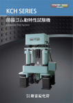
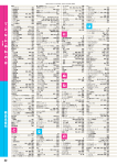
Material
Test System
This system is widely applicable to various tests with excellent function
and high reliability,and it finds the proprieties of materials speedily.
For the Solution
This system is widely applicable to various tests with excellent
マテリアルの適性をスピーディーに見いだす。
幅広い適用試験に加え、高機能・高信頼性を実現しました。
厳しい競争環境を勝ち残るために進められる新製品や新材料の開発。そして開発材料の適性を正確に
判断し、信頼を獲得していくには強度評価など各種のテストが欠かせません。つまりテストの精度と
スピードが開発の成果に大きな影響を与え、ひいては企業の盛衰をも左右することを意味します。サ
ギノミヤのダイナミックサーボ「Material Test System」は、サギノミヤの永年にわたるダイナミック
サーボ試験機の技術蓄積とノウハウを結集して誕生させた汎用材料試験機です。各種金属からプラス
チックス、さらに複合材やコンクリート、岩石など多彩な材質の試験が可能です。幅広いテスト材料
に対応すると同時に高機能・高信頼性を実現、優れたコストパフォーマンスを発揮します。近年急速
に高まっているデジタルコントロールニーズに合せた完全フルデジタル対応です。さらに機能アップ
や既存試験データなど、外部コンピュータ活用やLAN接続も容易に実現でき、ハード・ソフト両分
野のオプション製品も幅広く用意しています。
Evaluation of the strength and other various tests are indispensable for precisely judging the properties of developed materials and
acquiring their reliability in the process of developing new products and materials so as to remain undefeated in severe competitive
environments. The accuracy and speed of tests will largely affect the development results to have an influence upon the ups and
downs of enterprises. Saginomiya' s dynamic servo [Material test System] has been developed as a general-purpose material test
system by concentrating our long-years' accumulated technical data and know-how on dynamic test systems. It is applicable to the
tests of various materials ranging from various metals to plastics, composite materials, concrete, rocks, and other versatile materials.
It widely complies with various test materials with excellent functions, high reliability, and outstanding cost performance. It is fully
digital to conform to the digital control needs which have been increasingly demanded in recent years. This system can easily utilize
an external computer and LAN connection for grading up its functions and utilizing past test data. Various option hardware and software products are prepared.
HI
RELIABILITY
WIDE
DOMAIN
GOOD
PERFORMANCE
functions and high reliability, and it finds the proprieties of materials speedily.
Meet the Aim
Purposes aand aims of tests can be realized straight.
試験の目的と狙いがストレートに実現できます。
1. 引張試験、圧縮試験、引張−圧縮繰返し試験が行えます。
各種金属材料はもとより、木材、ゴム、プラスチックス、セラミックス、
あるいは複合材といったように、きわめて幅広い材料のテストが可能です。そして引張試験、
圧縮試験はもとより、引張-圧縮繰返し試験など組み合せた試験も可能です。
2. 高温炉、高周波誘導加熱装置、恒温槽、極低温槽などの
取り付けが可能なワイドな試験空間を有しています。
特殊環境試験のセットアップが容易にできます。
3. 時代にマッチしたフルデジタル対応です。
時代が求める高速性をDSP技術により実現すると同時に、制御レンジの自動切換えや
多チャンネル適応制御などにより、信頼性の高い試験が行えます。
またAGC機能(デュアルループ)
を付けて振幅安定性を向上させています。
4. ショックレスで制御モード切換えができます。
5. チャッキングモード機能付きでテストピース取付けが容易です。
チャッキングモード機能を用意していますから、テストピースが簡単に取付けられるほか、
設定も非常に容易です。
6. Windows対応、LAN接続が可能です。
柔軟性に富み汎用的な活用が可能なWindowsに対応しています。また、LANと接続することにより、
外部データなどのコンピュータ間転送も可能です。
1. This system can carry out the tension test, compression test, and tension-compression repetitive test.
It is applicable to the tests of various materials ranging from various metals to wood, rubber, plastics, ceramics,
and composite materials. It can execute the tension-compression repetitive test and other combined tests in addition
to the tension test and compression test.
2. A wide test space enough to mount an electric furnace, a high-frequency-induction heating system,
a constant temperature chamber, a cryogenic bath, and others.a
This system can easily set up special environmental tests.
3. Full- digital system satisfying the demands of the times
This system has realized speedy test processing by means of DSP technology to satisfy the demands of the times,
and it can execute highly reliable tests with its automatic switching of control ranges, multi-channel adaptive control,
and other functions. Its AGC function (dual loop) has improved the amplitude stability.
4. Control modes can be switched without any shock.
5. A test piece is easily mountable due to the setting mode function.
The setting mode function ensures easy mounting of a test piece and very easy setting.
6. Applicable to Windows and connectable to LAN
This system is applicable to flexible and general-purpose use Windows. By connecting this system to LAN,
it can transfer external data between computers
4
試験分野
(試験目的)
■ 引張−圧縮繰返し試験
■ 引張試験
■ 圧縮試験
■ 曲げ試験
■ 高温強度試験
■ 極低温疲労試験
■ 腐食疲労試験
■ 破壊靭性試験
Test fields (Purposes of tests)
*Tension-compression repetitive test
*Tension test
*Compression test
*Bending test
*High-temperature strength test
*Cryogenic fatigue test
*Corrosion fatigue test
*Fracture toughness test
試料分野
(試験対象物)
■ 試験片
各種金属 プラスチックス
木材 コンクリート
セメント 岩石 など
■ 構造部材
溶接部材 締結部材
継手類 など
Test fields (Test objects)
* Test pieces
Various metals Plastics Wood Concrete Cement Rock, etc.
* Structural members
Welded members Connected members Joints, etc.
* Windows is the brands US Microsoft Corporation in USA and other countries.
5
Comfortable System
Very flexible system configuration realizing its purposes
目的を確実に果たす、柔軟で拡張性の高いシステム構成。
サギノミヤMaterial Test Systemは、大きくは
「試験機本体」「コントローラ」「油圧装置」の3つの
主要ユニットで構成されます。さらに幅広いテスト
ニーズを満たす標準仕様とオプション仕様のハード
ウェアとソフトウェアを用意し、さまざまな試験目
的に適合したシステムとして提供できます。
Saginomiya's Material Test System is composed mainly of three
major units; [main frame], [controller], and [hydraulic unit]. In addition, this system conforms to various test purposes with its hardware
and software based on the standard specifications and option specifications which satisfy various test needs.
チャック
(オプション)
※P16∼17
Grips (Standard/Option)
検出器
(オプション)
※P18
Detector (Option)
環境装置
(オプション)
※P19∼20
Environmental Device (Option)
フレーム
(FT形/LT形)
※P14∼15
Frames (FTtype / STtype / LTtype)
油圧ユニット ※P21
Hydraulic Power Supply
HPT‐3∼HPT‐11
HPT‐15∼HPT‐74TW
6
メインコントロ−ラ
※P8∼10
Main Controller
Full Digital Controller Model 2810
コンピュータシステム
※P11∼13
CPU & Software
Full Digital Controller Model 2811
Digital Controller Model 2410
無停電電源装置
Battery
Main Controller
Digital servo controller
Model 2812
7
Full Digital Processing
digital servo controller 2810 series enables the intuitive
デジタルサーボコントローラ2810シリーズ採用。
試験プロセスに沿った直観的な操作が可能です。
DSPを駆使、高速性を実現
DSP技術(Digital Signal Processing)を駆使することにより、試験機
に必要な高速性を実現しています。
全センサチャンネルが独立したオートレンジ機能
全センサのチャンネルがそれぞれ独立した自動レンジ切換え機能
(オートレンジ機能)を備えています。また、外部からのアナログ信
号に対してもオートレンジ機能で32ビットのデジタルデータ値に変
換して制御します。8レンジ(×128)まで対応しています。
High-speed processing has been realized by driving DSP.
High-speed processing required for the test system has been realized by driving DSP (Digital Signal Processing) technology.
An automatic range switching function being independent in all
sensor channels
All sensor channels provide an independent automatic range switching function (automatic range function). Sensor signals are converted by the automatic range function into 32-bit digital data values for
control. Applicable to 8 ranges (×128)
多彩な制御。計測チャンネルの選択が可能
Model 2810シリーズにおいては、1 servoからマルチservoまで対応
可能であり、2812形の1 servo×4センサから、2811形の4servo×4セ
ンサまで多彩な選択が可能です。
Versatile control and measuring channels are selectable
Model 2810 seriesis applicable from 1 servo to multi-servo, and versatile channels are selectable from 1 servo×4 sensors in model
2812 to 4 servo×4 sensors in model 2811.
32bit内部ファンクションジェネレータ
内部ファンクションジェネレータは32ビット長の分解能を有しま
す。内部ファンクションジェネレータの信号、標準試験プログラム
ソフトから生成される信号、または外部から入力されるアナログの
信号で運転できます。内部に組込まれた関数波形は標準で〈サイ
ン・三角・矩形・ハーバーサイン・ランプ波〉です。
リモートコントローラ
オプションのリモートコントローラを取り付けることにより、試験
機本体側において、アクチュエータの微動作動を行うことができ、
試験体のセッティングが容易になります。
サギノミヤデジタルサーボコントローラは、DSP(Digital Signal
Processor)を搭載したサーボコントローラで、制御ループはデジタ
ルバスで結合されており、アナログ方式・ハイブリッド方式に比べ
格段の制御安定性及び対ノイズ特性を向上させた最新の技術を集約
したサーボコントローラです。
32-bit internal function generator
The internal function generator has the resolution of 32-bit length.
The system can be operated by internal function generator signals,
signals from standard test program software, or external input analog signals. Function waveforms (sine, triangle, square, haversine,
and ramp wave) are internally assembled as standard waveforms.
Remote controller
By mounting the option remote controller,the actuator can be operated finely on the tester main unit side to ensure easy sample setting.
HOST
CPU
GP-IB
HDD 2.1GB
MAIN CPU
Card PC 4MB
MAIN
BUS
DSP 2
DSP 1
SAGINOMIYA digital controller is a servo controller equipped with
DSP (Digital Signal Processor), and its control loop is connected
with a digital bus. By integrating the latest technology, this servo
controller is characterized with remarkable controlled stability and an
improved noise characteristic as compared with the analog system
and hybrid system.
8
MODEL 2810
LCD/SW
Servo amplifier
Servo valve
SENS COM
AC amplifier
GAGE amplifier
Displacement
Load
SENS COM
CONTROL
BUS
DC
Voltage and
other Variables
operation according to the test processes.
メインコントローラ仕様
Main controller Specification
■ Model 2810
試験条件の設定
CPUキーボードでCRT画面上に対話形式にて入力およびリモートコントローラにて設定
Set of test conditions
Inputting to the CRT using key board and remote controller.
制御、計測チャンネル
変位・荷重・ひずみ等制御モード最大8チャンネル
Control and measurement channel
displacement, load, strain and other.
レンジ切換
Range change
制御・計測ともオートレンジ
(×1、×2、×4、×8、×16、×32、×64、×128の8レンジ)
Automatic range switching is avaiable for both control and measurement.
(8 ranges including ×1, ×2, ×4, ×8, ×16, ×32 and ×64 ×128)
リミッタ
各センサチャンネル独立で、最大・最小それぞれ16bitの精度で設定可能
Limiter
With each independent sensor channel, the maximum and minimum can be set up with a precision of 16-bits.
較 正
各センサチャンネルとも較正データにより自動較正
Calibration
For each sennsor channel, automatic calibration is avaiable using the calibration data.
発生波形
サイン波・三角波・矩形波・ランプ波
Generated waveform
Sine wave, triangular wave, rectangular wave, and ramp wave
発生周波数
Generation frequency
0.001∼500Hz
ランプ波
0.001∼100, 000S
(30ステップ)
Ramp wave
0.001∼100,000S (30 steps)
波形分解能
Waveform resolution
32bit
一定振幅調整機能
(AGC)
標準装備
(AGC/AMC,
Automatic Gain Control (AGC)
Standard equipment (AGC/AMC, MAX/MIN, Fundamental wave/Average value)
周波数掃引発振
対数、リニア選択
(片方向時間 0.001∼999,
Frequency sweep
log, linear (0.001∼999, 999S Time of one way)
チャッキングモ−ド
変位制御、荷重リミット/変位・荷重同時制御
(Cレンジ)
Setting mode
Displacement FB, load limiiter, /Displacement FB, load FB (C range)
試料装着時の過負荷防止
標準装備
Overload prevension during test
Standard equipment
アクチュエータの手動操作
リモートコントローラにて上下可能
Manual operation of the actuator
Movable up and down by remote controller.
コンピュータシステム
コンパック
(IBM対応)
Computer
Compaq (similar IBM) Windows is available.
データサンプル時間
最大100μs
Data smple time
Maxmum 100μs Simulataneity between channels:within 1μs.
入出力機能
外部入力:±10V/F.S.
I/O function
External input:±10V/F.S. Data Output : ±10V/F.S
MAX/MIN,
基本波/平均値)
999S)
Windows対応
チャンネル間の同時性:1μs以内
データ出力:±10V/F.S
9
■ Model 2410
基本仕様
Standard Specifications
コンセプト
制御に必要な機能を1パネルに納めたオールインタイプ
Concept
All-in-one type which includes all necessary functions in One-panel
制御方式
フルデジタル制御
Control type
Full-digital control
制御モード
変位、荷重(標準装備)
Control mode
Displacement, Load(Standard)
制御モード数
最大4ch
Quantity of control Ch.
Max. 4ch.
SPAN/MEAN、MAX/MIN
AGCモード
Span/Mean,Max/Min
AGC Mode
間接モード
Indirect mode
ディスプレイ
6.5型
Display
6.5 inch
周波数:0.001∼200.0Hz 正弦波、三角波、矩形波
Frequency:0.001∼200.0Hz Sine,Triangular,Rectangular
波形
ランプ波:0.1∼100.000s
Waveform
Ramp
スイープ時間:0.01∼999.999s
Sweep
リミッタ機能
搭載モードすべてに対しオーバーリミット、4ポイントリミッタ機能あり
Limit function
Over limit:4-point limit function for all control mode
モニター出力
±10V(4ch)BNC端子
Monitor output
±10V(4ch) BNC terminal
リモコンBox
リモコンBox(オプション)
を取付けると、アクチュエーター側で供試体の取付け、取外しができます。
Remote Control Box
By equipping Remote Control Box(Opsion),setting and removal of the specimen at the actuator side is enabled
内蔵(標準)
油圧操作回路
Built-in (Standerd)
Hydraulic Operation Cycle
オプション:集中油圧源対応
Opsion:Response to the Concentrating Hydraulic Unit
インターフェイス
Interface
GP−IB
単軸疲労試験ソフト
オプションソフト
Single Actuator Fatigue Test
Option Software
破断ソフト
Breaking Test Software
電源
Power
外形寸法
Dimension
AC100V 50/60Hz 0.5kVA
420×160×450
関連特殊MODEL
MODEL 2411:油圧操作部なし(油圧操作別パネルタイプ)
Special MODEL
Without Hydraulic controler (without Hydraulic panel type)
MODEL 2412:LCD(表示部)なし(外部コンピュータ操作タイプ)
Without LCD (Operated by outer computer type)
10
Easy & Sure Operation : Software
試験目的に合わせた、的確・スピーディーな処理が可能です。
Precise and speedy processing is possible according to test purposes.
■ ソフトウェア
(標準)
:Software (Standard)
■ 高サイクル疲労試験
材料の高サイクル領域での挙動の解析およびS−N特性測定のた
めに使用します。
通常、丸棒または平板試験片を使用し、荷重または伸び
(歪)
制御
により試験片にサイン波負荷を与え、その間の荷重、歪のピーク
値および指定されたサイクル数でのヒステリシスループの記録を
行います。
High-cycle fatigue test
This system is used for analyzing the behaviors of materials in a
high cycle range and measuring the S–N characteristic. A circular rod or a flat plate test piece is normally used, and a sine wave
load is applied to the test piece by the load or elongation (strain)
control to record the peak load and strain values and the hysteresis loop in the specified cycle number during the test.
■ 低サイクル疲労試験
材料の低サイクル領域でのS−N疲労特性を解析するために使
用します。材料に三角波、または台形波で負荷を与えることで、
繰返しによるヒステリシスの変化、塑性歪の変化、クリープ特
性などが解析できます。
Low cycle fatigue test
This system is used for analyzing the S–N fatigue characteristic
in a low cycle range of materials. By applying a triangle wave
load or a ramp wave load to each material, a change of repetitive
hysteresis, a change of plastic strain, creep characteristic, and
other characteristics can be analyzed.
■ 静的試験
伸び(歪)制御により材料に一定速度の荷重を与え、
材料の静的特性値を求めます。
[解析方法]
*荷重、伸びの最大値
*最大応力、最大歪
*破断応力(荷重)
*ヤング率
*0.2%(0.02%)耐力
*上・下降伏点(歪硬化指数)
Static test
A static characteristic value of each material is obtained
by applying a load to a material at a constant speed
by the elongation (strain) control.
[ Analytical methods ]
* Maximum values of load and strain
* Maximum stress and maximum strain
* Rupture stress (load)
* Young's modulus
* 0.2% (0.02%) yield strength
* Upper and lower yield points (Strain hardening exponent)
11
■ ソフトウェア
(オプション)
:Software (Options)
■ K1C 試験
CT試験片または三点曲げ試験片を使用し、ランプ波入力で等
速COD制御により材料を破断しK1Cを求めます。
K1C test
K1C is obtained by breaking a CT test piece or a three-point bending test piece by means of uniform COD control with ramp wave
inputs.
■ CTOD試験
予亀裂が導入された三点曲げ試験片を使用し、等速COD
(または
変位)
制御により、試験片の破壊靭性を求めます。
CTOD test
The rupture toughness of a three-point bending test piece is
obtained by uniform COD (or displacement) control after introducing previous fatigue crack to the test piece.
■ ΔK試験実行
CT試験片または三点曲げ試験片を使用し、コンプライアンス法
により亀裂長さを自動追尾し、ΔKを求めます。
ΔK一定、ΔK漸増
(漸減)
試験を行い、da/dN―ΔKの関係を
求めます。
Delta K test
Delta K is obtained by automatically tracking the crack length of
a CT test piece or a three-point bending test piece by means of
the compliance method. The da/dN–ΔK relation is obtained by
the ΔK constant and ΔK gradual increase (gradual decrease)
test.
■ ΔK解析
ΔK試験実行にて取得したda/dN-ΔKの生デ−タをプロットしモニ
タします。
Delta K analysis
Raw data of da/dN–ΔK obtained by executing ΔK test are plotted and monitored.
12
■ J1C試験
除荷コンプライアンス法により、一本の試験片から亀裂増分、
負荷
エネルギーを計算し、J1C値、R曲線等を求めます。
J1C test
The J1C value, R curve, etc. are obtained by calculating the crack
increment and load energy from a test piece based on the loading compliance method.
■ 静的曲げ試験
曲げ試験片にランプ波による等速度の静的負荷を与え、曲げ試験
を行います。
Static bending test
The bending test is done by applying a uniform static load to a
bending test piece by means of a ramp wave.
■ 熱疲労試験
熱サイクル試験
温度一定試験
Thermal fatigue test
Thermal cycle test
Constant temperature test
■ セラミックス試験
Ceramics test
■ LAN監視システム:事務所内で各試験機の状況把握ができます。(オプション)
LAN Observation system:Possible to grasp state of each test system without moving from the controller room.(Option)
事務所
試験室
Controller room
常時モニター/見たい時起動
どちらでも可能
Always monitor/Start up when
the monitoring is desired.
The either way is possible.
Test laboratory
LAN回線
LAN circuit
試験機A
Test system A
試験機B
Test system B
試験機C
Test system C
13
Certain Function:Hardware
Precise response and reliable functions
的確な応答と確実な機能性を誇ります。
■ 試験機本体
(フレーム)
:Main Frame
FT形フレーム
試験機本体のもっとも標準的な本体
(フレーム)
で、試験片テストに適
しています。標準タイプで200kNまでの容量に対応しています。
※アクチュエータの上部クロスヘッドへの取付も可能です。
FT type frame
This is the most standard main frame suitable for testing test pieces.
Its standard type is applicable to the capacity of 200kN.
*The actuator can also be mounted to the upper cross head of this
frame.
ST形フレーム
試験片によるテストに加えて、構造物など大形供試体に適しています。
標準タイプで300kNまでの容量に対応しています。
ST type frame
This is suitable for structures and other large samples in addition to
the test of test pieces. Its standard type is applicable to the capacity
of 300kN.
LT形フレーム
ST形フレームで容量が高い試験用です。
標準タイプで2MNまでの容量に対応しています。
LT type frame
This is suitable for a high-capacity test of structures, other large
samples, and test pieces specified in ST type frame.
Its standard type is applicable to the capacity of 2MN.
14
写真
(mm)
NFT
FTB
FTC
2250
2200
2500
65±30
65±30
65±30
85±50
85±50
85±50
C
410∼1210
300∼1100
375∼1275
D
50
50
128
E
400
480
630
F
780
820
1010
G
255
370
425
H
550
550
670
I
φ65
φ100
φ130
D
A
C
B
I
A
H
B
G
F
E
(mm)
ST―10S
A
D
C
A
I
B
I
G
F
E
(
ST―20W
ST―30S
ST―30W
140
140
150
150
155
155
C
225∼1025 225∼1025 266∼1266 266∼1266 825∼1825 825∼1825
D
(225±100)(225±100)(266±100)(266±100)(278±100)(278±100)
E
2000
2000
2000
2000
3000
F
1100
1500
1100
1500
1100
1500
G
φ100
φ100
φ130
φ130
φ160
φ160
H
700
1000
670
1070
670
1100
I
200
200
200
200
200
200
T溝
3本
4本
3本
4本
3本
4本
T1
18
18
28
28
28
28
T2
30
30
46
46
46
46
T3
30
30
48
48
48
48
T4
12
12
20
20
20
20
)寸法は±100mmストロ−ク時の寸法です。
3000
Parenthesized sizes in ( ) show the
sizes in ±100mm stroke.
T3
T1
ST―20S
(2400) (2400) (2500) (2500) (2775) (2775)
B
H
ST―10W
(mm)
T4
T2
LT―300
LT―500
LT―1M
LT―2M
A
(2972)
(3540)
(3950)
(6516)
B
225
240
500
800
C
550∼1550
600∼2100
650∼2650
900∼3900
C
A
D
D
G
J
H
B
I
E
F
(
(283±100) (296±100) (351±100) (490±100)
E
3000
3000
3200
5000
F
1500
1500
1500
2040
G
500
500
600
700
H
1000
1000
1000
1000
I
150
300
500
770
J
φ130
φ130
φ130
φ220
T溝
3本
3本
2本
2本
T1
28
28
28
36
T2
46
46
46
60
T3
48
48
48
57
T4
20
20
20
25
)寸法は±100mmストロ−ク時の寸法です。
Parenthesized sizes in ( ) show the
sizes in ±100mm stroke.
15
Hardware:チャック:Grips (Option)
ねじ形
スプリット形
平板形
Screw type
Split type
Flat plate
35
(25)
l
l
h
70(50)
R
50
φd
R
φd1
D
R
φd
M
60
L
L
a) 平滑形試験片
a) 平滑形試験片
(a) Flat test piece
(a) Flat test piece
140(130)
82(67)
300(260)
平板試験片
M
R
φd1
φd
D
R
φd
Flat plate test pece
h
L
L
b) 砂時計形試験片
b) 砂時計形試験片
(b) Hourglass type test piece
(b) Hourglass type test piece
ねじ式丸棒チャック
スプリット式丸棒チャック
平板チャック
Screw type round bar grips
Split type round bar grips
Flat plate grips
形 式
MGS―2
Type
動的最大荷重
(kN)
±20
±50
±100
2.5
3.5
6.5
d
6
8
10
L
120
120
180
Maximum dynamic load
質量
(㎏/1個)
Mass (kg/pc)
適合試験片
寸法
(mm)
Applicable test
piece size (mm)
16
MGS―5 MGS―10
M
8
16
形 式
動的最大荷重
(kN)
Maximum dynamic load
質量
(㎏/1個)
30
35
40
I
25
35
35
適合試験片
寸法
(mm)
Applicable test
piece size (mm)
±20
±50 ±100 ±200
5
7
16
25
d
8
10
10
10
L
160
160
200
250
Mass (kg/pc)
20
R
MGB―2 MGB―5 MGB―10 MGB―20
Type
D
20
30
40
55
d1
18
18
25
35
R
30
40
40
50
I
30
30
50
60
h
12
12
16
25
形 式
MGP―2
Type
動的最大荷重
(kN)
Maximum dynamic load
質量
(㎏/1個)
Mass (kg/pc)
MGP―5 MGP―10
±20
±50
±100
12
14
25
幅
MAX.50 MAX.50 MAX.70
適合試験片 Width
寸法
(mm) 長 さ
70
70
70
Applicable test
piece size
(mm)
Length
厚 さ
Thickness
1∼5
3∼10
2∼10
油圧チャック
Hydraulic grips
形 式
HG―5
HG―10
HG―20
HG―30
HG―50
HG―100
HG―200
±50
±100
±200
±300
±500
±1000
±2000
25
45
120
160
320
500
1800
Plate
width
50
70
95
100
100
150
250
板 厚
∼15
Type
動的最大荷重
(kN)
Maximum dynamic load
質量
(㎏/1個)
Mass (kg/pc)
板 幅
平 板
適合試験片
寸法
(mm)
Flat
plate
Applicable test
piece size (mm)
丸 棒
Round
Bar
Plate
thickness
直 径
Diameter
2∼18
2∼20
2∼20
10∼30
10∼30
20∼40
9∼25
20∼40
20∼40
30∼50
30∼50
40∼60
50∼65
60∼80
5∼10
5∼15
15∼25
15∼25
20∼35
20∼35
35∼50
10∼20
15∼25
25∼35
25∼35
35∼50
35∼50
50∼65
35∼45
50∼65
50∼65
65∼80
17
Hardware:検出器:Detector (Option)
軸伸び検出器 Axial extenso meters
形 式 Type
ETM―06―003
ETM―10―010
使用温度範囲 Working temperature range
標点距離
(mm)Gauge length
測定範囲
(mm)Measuring range
使用周波数
(Hz) Working frequency
ETM―10―020
ETM―20―030
6
10
10
20
25
50
±1
±2
±3
±3
±3
MAX10
MAX20
0.5%F.S以内
(1.0%F.S以内)
開口変位検出器 Craek opening displacement
COD―05―020
COD―05―030
使用温度範囲 Working temperature range
標点距離
(mm)Gauge length
測定範囲
(mm)Measuring range
5
5
10
10
±3
±3
±5
MAX10
±1.0%F.S以内
径伸び検出器 Diamater extenso meter
標点距離
(mm)Gauge length
測定範囲
(mm)Measuring range
使用周波数
(Hz)Working frequency
非直線性 Non-linearity
18
COD―10―050
±2
非直線性 Non-linearity
使用温度範囲 Working temperature range
COD―10―030
RT∼60℃
使用周波数
(Hz)Working frequency
形 式 Type
ETM―50―030
±0.3
非直線性 Non-linearity
形 式 Type
ETM―25―030
RT∼60℃
(−40℃∼175℃)
DIM―10―005
RT∼60℃
6∼10
±0.5
MAX10
±0.5%F.S以内
Hardware:環境装置:Environmental Device (Option)
熱疲労試験装置実績例
真空高温炉試験装置実績例
An example of thermal fatigue test system results
An example of vacuum high-temperature furnace test system results
温度範囲
Temperature range
300℃∼1200℃
セラミック加熱用
金属加熱用
For heating ceramics
For heating metals
1000℃∼1600℃
800℃∼1200℃
タングステンロッドヒ−タ
モリブデンロッドヒ−タ
Tungsten rod heater
Molybdenum rod heater
加熱方式
高周波誘導加熱方式
(直接及び間接誘導加熱)
温度範囲
Heating system
High-frequency induction heating system (Direct and indirect induction heating)
Temperature range
制御方式
PID制御による、熱サイクル及び温度一定制御
加熱方式
Control system
Heat cycle and temperature constant control by PID control
Heating system
加熱速度
RT∼1000℃まで約70s
制御方式
Heating speed
Approx. 70s from room temperature to 1000℃
Control system
冷却方式
エア−サ−ボ方式
(PID制御による加熱、冷却の同時制御)
温度分布
Cooling system
Air servo system (Simultaneous control of heating and cooling by PID control)
Temperature distribution 10℃P-P (Soaking zone φ50mm×H70mm) 10℃P-P (Soaking zone φ10mm×H20mm)
冷却速度
1000℃∼300℃まで約60s
到達真空度
Cooling speed
Approx. 60s from 1000℃ to 300℃
Attainable vacuum
温度分布
15℃以内
(GL15㎜間 at 900℃)
真空ポンプ
油回転ポンプ及び油拡散ポンプ
Temperature distribution
Within 15℃ (GL-15mm at 900℃)
Vacuum pump
Oil rotary pump and oil diffusion pump
到達真空度
10−3Paオ−ダ
(900℃一定加熱時)
真空計
Attainable vacuum
10−3 Pa order (by constant heating at 900℃)
Vacuum gauge
排気速度
10−3Paオ−ダまで約40min
電 源
Pumping speed
Approx. 40min. up to 10−3 Pa order
Power supply
真空ポンプ
タ−ボ分子ポンプ及び油回転ポンプ
冷却水
Vacuum pump
Turbo molecular pump and oil rotary pump
Cooling water
真空計
ピラニ真空計及び電離真空計
Vacuum gauge
Pirani gauge and ionization gauge
電 源
3相200V 3kVA
Power supply
3-phase 200V, 3kVA
冷却水
Cooling water
PID制御
PID control
10℃P-P(均熱ゾ−ンφ50mm×H70mm) 10℃P-P(均熱ゾ−ンφ10mm×H20mm)
10−4Paオ−ダ
(室温)
10−4 Pa order (at room temperature)
ピラニ真空計及び電離真空計
Pirani gauge and ionization gauge
3相200V 3kVA
(真空ポンプ)、単相200V 21kVA
(電気炉)
3-phase 200V, 3kVA (vacuum pump) Single-phase 200V, 21kVA (electric furnace)
35L/min at 30℃
25L/min at 30℃
19
Hardware:環境装置:Environmental Device (Option)
恒温槽
Constant temperature chamber
高温炉
極低温槽
Furnace
Cryogenic bath
恒温槽 Constant temperature chamber
温度範囲
Temperature range
恒温恒湿槽 Constant-temprature & humidity chamber
−30∼+150℃
温度分布
±3℃
(空室)(empty room)
Temperature distribution
昇温時間 Heating time
湿度(%)
Humidity 90
120min
(RT∼−30℃)
一元冷凍方式
One-dimensional refrigeration system
槽内寸法
二元冷凍方式
Two-dimensional refrigeration system
W340×D460×H550mm
Internal dimensions of bath
電 源 Power supply
3相200V 8kVA 3-phase ※
3相200V 10kVA 3-phase ※
冷却水 Cooling water
30L/min at 30℃
45L/min at 30℃
50
30
25 40
Fig1 運転範囲
Fig.1 Operation range
※高温槽の場合、60∼MAX450℃まで可能です。
※Applicable over a range of 60~ max. 450°C in case of high-temperature chamber
高温炉 Furnace
温度範囲
Temperature range
温度分布
Temperature distribution
外形寸法
External dimensions
構 造 Structure
温度範囲 25∼90℃ Temperature range
湿度範囲 30∼90% Humidity range
90min
(RT∼+150℃)
降温時間 Cooling time
冷凍機 Refrigerator
−50∼+150℃
極低温槽
300∼700℃
300∼1500℃
±3℃
(空炉)±3℃ (empty furnace)
φ335×H460mm
φ450×H500mm
半割型環状炉 Half-split annular furnace
90
温度(℃)
Temperature
Cryogenic bath
到達温度
約−196℃
Attainable temperature
Approx. −196℃
槽構造
真空断熱式
Bath structure
Vacuum heat insulation system
槽内寸法
Internal dimensions of bath
φ260×440mmL
加熱方式
ニクロム線ヒ−タ
二珪化モリブデンヒ−タ
冷却方式
Heating system
液体窒素浸積式
Nichrome wire heater
Molybdenum disilicide heater
Cooling system
Liquid nitrogen immersion system
電 源 Power supply
冷却水 Cooling water
20
単相200V 6kvA Single-phase 200V, 6kVA
10L/min at 30℃
制御方式
液体窒素液面制御
Control system
Liquid nitrogen liquid level control
Hardware:油圧ユニット:Hydraulic Power Supply
小型の省スペースタイプ、しかもハイパワーで低騒音です。
Small, low-noise, and high-power space-saving type
油圧ユニットは、小型でハイパワー、そして低騒音が特長のMaterial Test Systemのパワー供給源です。油圧回路にはサーボバルブ保護の
ため、アブソリュート3μの高密度フィルタが取付けられています。その他、オイルクーラ・圧力計・油面計・自動給水弁が標準装備され
ています。
安全装置として、油温上昇防止
(50℃設定)
・油面低下・フィルタ目詰り警報回路を備えています。
ポンプは超低騒音ポンプを採用し、マルチドライブが可能なように油圧吐出口は2出力となっています。
This small, low-noise, and high-power hydraulic unit serves as the power feed source of the material test system. Its hydraulic circuit is
H
provided with an absolute 3μ high-precision filter for protecting its servo valve. In addition, an oil cooler, a pressure gauge, an oil level
gauge, and an automatic water feed valve are mounted as standard equipment.
This hydraulic unit is also equipped with an oil temperature-rise preventive device (set to 50°C), an oil level drop alarm circuit, and a
filter stuffing preventive alarm circuit as safety devices.
A very low-noise pump is used and two hydraulic discharge ports are provided for multi-drive.
B
H
B
A
A
D
D
W
W
HPT‐3∼HPT‐11
油圧ユニット
ITEM
定格圧力
Hydraulic Power Supply
MODEL
Reated Oil Pressure
定格流量
Reated Flow ※1
電動機
Electric Motor
消費電力
Input
冷却水量
Required Water Flow
適合冷却塔
Cooling Tower ※2
騒 音
Noise
HPT‐15∼HPT‐55
※1
寸 法
Dimensions
油 圧
冷却水
オイルタンク容量
Reservoir Capacity
質 量
Mass approx ※3
W
D
H
A
B
HPT―3
HPT―5
HPT―7
HPT―11
HPT―15
HPT―19
HPT―22
HPT―30
HPT―37
HPT―45
HPT―55
MPa
20.5
20.5
20.5
20.5
20.5
20.5
20.5
20.5
20.5
20.5
20.5
L/min
6.9/6.8
9.2/11
14/14
19/23
31/30
42/39
52/51
68/62
87/82
106/104
136/129
kW
3.7
5.5
7.5
11
15
18.5
22
30
37
45
55
kVA
6
8
10
15
20
26
30
38
48
58
69
L/min
32℃
22
30
30
40
35
50
55
70
90
110
150
−
2
3
3
3
5
5
5
7.5
10
10
15
dB
66/66
68/68
70/70
72/72
75/75
76/76
77/78
79/80
80/81
81/82
82/84
mm
mm
mm
G Inches
Rc Inches
600
965
845
1/2
1/2
650
1020
880
1/2
1/2
650
1065
915
1/2
1/2
763
1130
1094
1/2
3/4
860
1580
961
1
3/4
860
1580
961
1
3/4
900
1720
1011
1
1
900
1720
1135
1
1
1030
1985
1304
1 1/4
1 1/4
1030
2035
1401
1 1/4
1 1/2
1030
2035
1304
1 1/4
2
L
48
60
60
90
130
130
190
190
350
350
350
200
200
210
265
730
750
1000
1050
1250
1400
1550
kg
※1 50Hz/60Hzの表示です。 ※1 50Hz/60Hz
※3 作動油を含んでいます。
※2 空冷方式も製作しております。
※2 it is manufacturing an aerial cooling system,too.
※3 it is the Mass which included Hydraulic oil.
21
Standerd Specification
FTシリーズ/FT series
試験機システム
Test machine system
動的最大荷重
Max. dynamic load
静的最大荷重
Max. static load
総
合
性
能
General performance
最大ストローク
Max. stroke
形 式/Type
FT―2
FT―3
FT―5
FT―10
FT―20
±kN
20
30
50
100
200
±kN
23
35
58
116
230
±mm
30 or 50
振幅特性
下図参照/See under page
Amplitude characteristic
制御モード
荷重、変位等4チャンネルまで可能
Controlled range
Possible up to 4 channels (load, displacement, etc.)
レンジ切換
オートレンジ
(×1∼128の8レンジ)
Range selection
Automatic range (8 ranges from x1 to 128)
静的荷重精度
ロードセル容量の±0.2%
Static load accuracy
±0.2% of load cell capacity
静的変位精度
全ストロークの±0.2%
Static displacement accuracy
±0.2% of full stroke
制御安定性
各レンジFSの±1.0%
Control stability
試
験
機
本
体
Test machine
本体フレーム
Road frame
剛性
(クロスヘッド・テーブル間500mmにおいて)
±1.0% of FS in each range
NFT
FTB
mm/kN
EFH―20
Detector
Actuator
EFH―50
荷重検出器
FLC形
(せん断歪み形)
FLC type (Shearing strain type)
0.00065
EFH―100
変位検出器
差動トランス
(アクチュエータ内蔵)
Displacement detector
Differential transformer (with built-in actuator)
丸棒チャック
オプション
Grips
Round bar grip
Option
Hydraulic unit
EFH―30
Load detector
チャック
油
圧
装
置
NFT=0.0016 FTB=0.0012
Rigidity (at 500mm on cross head table)
アクチュエータ
検
出
器
FTC
形 式/Type
油圧ユニット
Hydraulic power supply
サーボ弁
Servo valve
アキュムレータ
Accumulater
EFH―200
スプリット形丸棒チャック
Split type round bar grip
形 式/Type
HPT―5
HPT―5
HPT―7
HPT―15
HPT―19
形 式/Type
76―182
76―182
76―182
76―183
76―184
容 量/Capacity
0.5L
1L
制
御
装
置
Controller
Model2810フルデジタルコントローラ:コンピュータ制御/マニュアル制御(計測チャンネル:最大8ch)
Full digital controller:Computer control/Manual control(Measuring channels:Max.8 channels)
コントローラ
Controller
Model2811フルデジタルコントローラ:コンピュータ制御
(計測チャンネル:最大8ch)
Full digital controller:Computer control(Measuring channels:Max.8 channels)
Model2410フルデジタルコントローラ:コンピュータ制御/マニュアル制御(計測チャンネル:最大4ch)
Full digital controller:Computer control/Manual control(Measuring channels:Max.4 channels)
Sinusoidal Amplitude Displacement (mm)
1000
100
10
1
0.1
0.1
1
10
Frequency(Hz)
FTシリ−ズ/FT series
22
100
1000
LSTシリ−ズ/LST series
STシリ−ズ/ST series
ST―2
ST―3
ST―5
ST―10
ST―20
ST―30
LST―30
LST―50
LST―100
LST―200
20
30
50
100
200
300
300
500
1000
2000
23
35
58
116
230
350
350
580
1160
2300
50 or 100
100
下図参照/See under page
下図参照/See under page
荷重、変位等4chまで可能
Possible up to 4 channels (load, displacement, etc.)
オートレンジ
(×1∼128の8レンジ)
Auto range (8 ranges from x1 to 128)
ロードセル容量の±0.2%
±0.2% of load cell capacity
全ストロークの±0.2%
±0.2% of full stroke
各レンジFSの±1.0%
±1.0% of FS in each range
EFH―20
ST―10S
ST―20S
ST―30S
ST―10W
ST―20W
ST―30W
0.002
0.001
EFH―200
EFH―30
EFH―50
EFH―100
LT―300
LT―500
LT―1M
LT―2M
0.00067
0.00067
0.0004
0.0003
0.00025
EFH―300
EFH―300
EFH―500
EFH―1M
EFH―2M
FLC形(せん断歪み形)
FLC type (Shearing strain type)
差動トランス(アクチュエータ内蔵)
Differential transformer (with built-in actuator)
スプリット形丸棒チャック
Split type round bar grip
HPT―5
HPT―7
HPT―15
HPT―22
HPT―45
HPT―55
HPT―22
HPT―37
HPT―55
HPT―74TW
76―182
76―183
76―183
76―184
72―187
72―188
72―186
72―186
72―187
72―188
0.5L
1L
3L
3L
←
←
←
1000
Sinusoidal Amplitude Displacement (mm)
Sinusoidal Amplitude Displacement (mm)
1000
100
100
10
1
0.1
0.1
1
10
Frequency(Hz)
STシリ−ズ/ST series
100
1000
10
A
1
B
C
0.1
0.01
0.1
1
Frequency(Hz)
10
100
LSTシリ−ズ/LST series
LST-30,50
LST-100
LST-200
23
Material
Test System
安全に関するご注意
!
ご使用の前に「取扱説明書」をよく
お読みの上、 正しくお使いください。
製品改良の為、
予告なしに仕様、
構造などの変更を行うことがあります。
お問合せは
! NOTES FOR SAFETY
Failure to read and follow all instruction carefully
before installing or operating the product could
cause personal injury and /or property damage.
Specifications are subject to change without notice.
For more detail information, contact
本 社
/東京都中野区若宮2−5
5−5 〒165−8907
試験機営業部
TEL 03 (3330) 7313
FAX 03 (3330) 7314
E-mail : [email protected]
大 阪 支 店 /大阪府吹田市広芝町1
8−1
2 〒564−0052
TEL 06 (6385) 8011
FAX 06 (6384) 0859
福 岡 営 業 所 /福岡市博多区博多駅前1−7−22 第14岡部ビル 〒812−0011
TEL 092 (436) 6001
FAX 092 (436) 6002
55-5, Wakamiya 2chome, Nakano-ku,
Tokyo 165-8907 Japan Tel: 03-3330-7313
E-mail : [email protected]
OSAKA BRANCH OFFICE: Tel: 06-6385-8011
FUKUOKA SALES OFFICE: Tel: 092-436-6001
URL: http://www.saginomiya.co.jp
URL: http://www.saginomiya.co.jp
初1999.4
z
2006.7