1
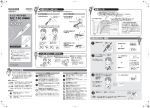
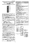
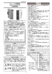
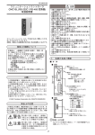
CP-UM-5131JE 注意 モジュール形調節計 DMC10E 取扱説明書 ・本器の取り付け・取り外し、および結線のときは、必ず 本器および接続機器の電源をすべて切ってください。感 電することがあります。 ・本器を分解しないでください。 故障の恐れがあります。 ・本器は仕様に記載された使用条件(温度、湿度、振動、衝 撃、取付方向、雰囲気など)の範囲内でお使いください。 火災、故障の恐れがあります。 ・本器の通風穴をふさがないでください。 火災・故障の恐れがあります。 ・本器への結線は定められた基準に従い、指定された電源、 および施工方法で正しく配線してください。 感電・火災・故障の恐れがあります。 ・本器のケース内部に線くず、切粉、水などが入らないよ うにしてください。 火災・故障の恐れがあります。 ・端子ねじは仕様に記載されたトルクで確実に締めてくだ さい。締め付けが不完全だと火災の恐れがあります。 ・本器の未使用端子を中継端子として使用しないでください。 感電・火災・故障の恐れがあります。 ・雷サージの恐れがある場合には、サージアブソーバ(サー ジ防止器)を使用してください。 火災、故障の恐れがあります。 モジュール形調節計 DMC10E をご購入いただき、まことにあ りがとうございます。 本書は、使用上の注意事項と仕様と結線だけを説明したもの です。 詳しい取り扱い方法、設定方法は別冊の モジュール形調節計 DMC10 取扱説明書「機能説明編」CPUM-5143 をお読みになり、正しくご使用ください。 ・本器を廃棄されるときは、産業廃棄物として各地方自治 体の条例に従って適切に処理してください。 ・本器のリレーは仕様に記載された寿命の範囲内で使用し てください。寿命範囲を超えて使い続けると火災、故障 の恐れがあります。 ご注文・ご使用に際しては、下記 URL より「ご注文・ご使用 に際してのご承諾事項」を必ずお読みください。 ・本器は電源投入後、約 10 秒動作しません。本器からのリ レー出力も同様に動作しないので使用する場合は注意し てください。 http://www.azbil.com/jp/product/cp/order.html お願い ・連結されたモジュール全体の消費電力の総和が 100W を 超えないでください。 火災、故障の恐れがあります。 この取扱説明書は、本製品をお使いになる担当者のお手 元に確実に届くようにお取りはからいください。 この取扱説明書の全部、または一部を無断で複写、また は転載することを禁じます。この取扱説明書の内容を将 来予告なしに変更することがあります。 この取扱説明書の内容については、万全を期しておりま すが、万一ご不審な点や記入もれなどがありましたら、 当社までお申し出ください。 お客様が運用された結果につきましては、責任を負いか ねる場合がございますので、ご了承ください。 ・連結されたモジュール全体に 2 系統以上の電源を供給し ないでください。 火災、故障の恐れがあります。 ・連結されたモジュール全体に本器の接続は 1 台にしてく ださい。 故障の恐れがあります。 ・この製品は電気の知識を有する専門の方が扱ってください。 ・計器の汚れを取る場合は柔らかい布でからぶきしてくだ さい。シンナー、ベンゼンなどの有機溶剤や洗剤は使用 しないでください。 © 1999-2014 Azbil Corporation All Rights Reserved. 安全上の注意 ・製造者が指定していない方法で機器を使用すると、機器 が備える保護が損傷する可能性があります。 この安全上の注意は、製品を安全に正しくお使いいただき、 あなたや他の人々への危害や財産への損害を未然に防止する ためのものです。安全上の注意は必ず守ってください。また、 内容をよく理解してから本文をお読みください。 ・本器に接続する機器または装置は、本器の電源、入出力 部の最高使用電圧に適した強化絶縁が施されている物を ご使用ください。 (リレー出力を除く) ●● 警告表示の意味 取り扱いを誤った場合に、使用者が軽傷を負う 注意 か、または物的損害のみが発生する危険の状態 が生じることが想定される場合。 警告 取り扱いを誤った場合に、使用者が死亡また は重傷を負う危険の状態が生じることが想定 される場合。 取り扱いを誤った場合に、使用者が死亡また 警告 は重傷を負う危険の状態が生じることが想定 される場合。 注意 取り扱いを誤った場合に、使用者が軽傷を負う か、または物的損害のみが発生する危険の状態 J1 形番構成 基本形番 CH 数 配線 方法 取り付け 追加処理 1 2 制御 オプ 出力 ション ■■ 取付場所 仕 様 屋内に取り付けてください。 DMC10E 4 C R 00 0 0 A 4CH 出力 コネクタ配線 リレー出力 なし なし なし UL 対応品 次のようなところには取り付けないでください。 ・仕様の範囲を超えた高温、低温、高湿度、低湿度になる ところ ・硫化ガスなど腐食性ガスのあるところ ・粉塵、油煙などのあるところ ・直射日光、風雨が当たるところ ・仕様の範囲を超えた機械的振動、衝撃のあるところ 各部の名称と機能 ・高圧線の下、溶接機および電気的ノイズの発生源の近く ■■ 本 体 ・ボイラなどの高圧点火装置から 15m 以内 ・電磁界の影響のあるところ EV1∼4動作ランプ :モジュール内の対象 CHのリレー接点が ONすると点灯します ・可燃性の液体や蒸気のあるところ ■■ モジュールの連結 本器はベース左右のコネクタで別のモジュールと連結で きます。 モジュールの連結は DIN レールへの取り付け、またはね じ取り付けを行う前に作業してください。 連結することで、各モジュールの電源および CPL 通信が 接続され、配線を省くことができます。 CPL 通信は、ベースの通信切り離しスイッチで切り離し ができます。 ■■ 取付方法 本器はベースをねじで取り付ける方法と DIN レールに取 り付ける方法のどちらでもお使いいただけます。 取り扱い上の注意 •本器は垂直な面に DIN レールストッパを下側にして取り 付けてください。 ■■ ベース ベースの取付ねじ穴2カ所をM3ねじで固定してください。 単位:mm (30) +0.9 30+0.3 通信切り離しスイッチ :左側に連結した 機器とCPL通信を 行わないときに 使用します 出荷時は CONNECT 側 です (連結されています) 10±0.2 M3 5 5 1 2 3 4 5 6 (100) 番号 信号名 1 DC24V (+) 2 DC24V(−) 3 使用禁止 CPL通信端子 :3線式RS-485の 接続端子です 番号 信号名 4 DA 5 DB 6 SG 78.5±0.2 電源端子 取付ねじ穴 DINレールストッパ :DINレールに固定 するとき使用します ●● ねじ取り付けの場合 レバー :本体を固定します 取付ねじ穴 :2カ所あります M3ねじでベースを 固定します ●● DIN レール取り付けの場合 DIN レールを固定したあと、DIN レールストッパを十 分引き出してからベースをレールに引っかけてくださ い。次に DIN レールストッパを上方にカチッと音がす るまで押し込んでください。 J2 ■■ 本体をベースに取り付ける ■■ CPL 通信の接続 フックを引っかけて、レバーがカチッと音がするまではめ 込んでください。 レバー CPL 通信(RS-485)は 3 線式接続です。 フック 例:5 線式計器との接続方法 外すときは、上部のレバーを押しながら手前に引いてください。 取り扱い上の注意 結 線 •本器には終端抵抗相当が内蔵されているので外部に終端 抵抗を接続しないでください。 •SG は必ず接続してください。接続しないと安定した通 信ができないことがあります。 拡張イベント (CH1) 11 11 12 13 14 NO 12 NC 13 仕 様 ■■ 仕 様 項 目 拡張イベント (CH2) 15 拡張 点 数 イベント出力 出力定格 14 15 拡張イベント (CH3) 16 17 18 19 20 16 NO 17 NC 18 拡張イベント (CH4) 19 一般仕様 NO: Normally Open (開) NC: Normally Close (閉) 20 ■■ 結線上の注意 ・端子部の結線は必ず圧着端子を使用してください。 結線が終わったら、通電前に接続して間違いのないこと を確認してください。 ・リ レー接点出力を除く入出力のコモン電圧は、30Vrms 以下、42.4V ピーク以下、DC60V 以下としてください。 ■■ 電源の接続 電源端子は次のように接続してください。 1 2 3 使用禁止 + − DC24V 電源はクラス 2 電源を使用してください。 取り扱い上の注意 仕 様 4点 出力形式 接点形式 接点定格 :リレー接点出力 :SPST/2 点、SPDT/2 点 :AC250V、1A DC30V、1A :10 万回以上(抵抗負荷) 寿 命 最小開閉仕様:5V、 10mA 過電圧カテゴリ:CategoryII(IEC60364-4-443, IEC60664-1) 動作種類 DMC10 の動作種類 * DMC10 にてバスイベント出力に設定することで有効 * 付加機能 各 DMC10 の同一バスイベント出力を OR する * 定格電圧 DC24V 消費電力 3W 以下(動作条件にて) 絶縁抵抗 1 次 -2 次間:DC500V 20M Ω以上 耐電圧 1 次 -2 次間:AC1500V 1min 電源投入時 10A 以下 突入電流 汚染度 Pollution degree 2 高 度 2000 m以下 本体・ 変性 PPE 樹脂、PC 樹脂 ベース材料 本体・ベース色 ライトグレー 動作条件 周囲温度 :0 ~ 50℃ 周囲湿度 :10 ~ 90%RH 電源電圧 :DC21.6 ~ 26.4V 振 動 :0 ~ 1.96m/s2 (10 ~ 60Hz X、Y、Z 各 2h) 衝 撃 :0 ~ 9.81m/s2 取付角度 : (基準面)± 10° 輸送保管 周囲温度 :- 20 ~+ 70℃ 条件 周囲湿度 :10 ~ 95%RH(結露なきこと) 振 動 :0 ~ 4.90m/s2 (10 ~ 60Hz X、Y、Z 各 2h) (ねじ取り付け) 衝 撃 :392m/s2 (DIN 取り付け) 196m/s2 包装落下試験:落下高さ 60cm (1 角 3 稜 6 面の自由落下法) 質 量 200g 以下 * 詳細はモジュール形調節計 DMC10 取扱説明書「機能説明編」 CP-UM-5143 をご覧ください •連結しているモジュール間は、電源が相互に接続されて います。 •連結しているモジュールのどれか一つに電源を供給して ください。 •電源は、連結しているモジュールの消費電力の総和を十 分にまかなえるものを選定してください。 •あき端子③は使用禁止です。 中継配線などに使用しないでください。 J3 ■■ 外形寸法図 単位:mm DINレールへの取り付け、 取り外しに必要な寸法 本体の取り付け、 取り外しに必要な寸法 〔ご注意〕 この資料の記載内容は、お断りなく変更する場合も (24) ありますのでご了承ください。 お問い合わせは、下記または当社事業所へお願いいたします。 本 社 北海道支店 東北支店 北関東支店 東京支社 〒100-6419 東京都千代田区丸の内 2-7-3 東京ビル ☎(011) 781 ー 5396 ☎(022) 290 ー 1400 ☎(048) 621 ー 5070 ☎(03) 6810 ー 1211 2 製品のお問い合わせは… 中 関 中 九 コールセンター : 〈アズビル株式会社〉 〈COMPO CLUB〉 部 西 国 州 支 支 支 支 社 社 店 社 ☎(052)324 ー 9772 ☎(06)6881 ー 3383 4 ☎(082)554 ー 0750 ☎(093)285 ー 3530 0466-20-2143 http://www.azbil.com/jp/ http://www.compoclub.com J4 1999年 4月 初版発行 ( R ) 2014年 5月 改訂15版 ( V ) CP-UM-5131JE CAUTION DMC10E Distributed Multi-channel Controller User's Manual • Before removing, mounting, or wiring the DMC10E, be sure to turn off the power to the DMC10E and all connected devices. Failure to do so might cause electric shock. • Do not disassemble the DMC10E. Doing so might cause faulty operation. • Use the DMC10E within the operating ranges (temperature, humidity, vibration, shock, mounting direction, atmosphere, etc.) recommended in the specifications. Failure to do so might cause fire or faulty operation. • Do not block ventilation holes. Doing so might cause fire or faulty operation. • Wire the DMC10E properly according to predetermined standards. Also wire the DMC10E using designated power leads according to recognized installation methods. Failure to do so might cause electric shock, fire or faulty operation. • Do not allow lead clippings, chips or water to enter the DMC10E case. Doing so might cause fire or faulty operation. Thank you for purchasing the DMC10E Distributed Multichannel Controller. This manual describes only precautions for ensuring correct use of the DMC10E Distributed Multi-channel controller, specifications and wiring. Be sure to keep this manual nearby for handy reference. For further details on correct use, read the DMC10 Distributed Multi-channel controller User's Manual (Description of Functions Version) CP-SP-1057E. • Firmly tighten the terminal screws at the torque listed in the specifications. Insufficient tightening of terminal screws might cause fire. • Do not use unused terminals on the DMC10E as relay terminals. Doing so might cause electric shock, fire or faulty operation. • If there is a risk of a power surge caused by lightning, use a surge absorber (surge protector) to prevent fire or device failure. Please read the "Terms and Conditions" from the following URL before ordering or use: http://www.azbil.com/products/bi/order.html • When disposing of the DMC10E, dispose of it appropriately as industrial waste in accordance with local bylaws and regulations. NOTICE Be sure that the user receives this manual before the product is used. • Use the relay on the DMC10E within the rated life described in the specifications. Continued use of the DMC10E outside of the rated life might cause fire or faulty operation. Copying or duplicating this user’s manual in part or in whole is forbidden. The information and specifications in this manual are subject to change without notice. • The DMC10E will not function for about ten seconds after turning the power ON. Pay attention to this when using the relay output for the DMC10E as an output signal. Considerable effort has been made to ensure that this manual is free from inaccuracies and omissions. If you should find an error or omission, please contact the azbil Group. In no event is Azbil Corporation liable to anyone for any indirect, special or consequential damages as a result of using this product. • Prevent the total power consumption of all linked modules from exceeding 100 W. Failure to do so might cause fire or faulty operation. • Do not supply power from two or more lines to all linked modules. Doing so might cause fire or faulty operation. © 2000-2014 Azbil Corporation All Rights Reserved. • Connect only one DMC10E to all linked modules. Failure to do so might cause the DMC10E to malfunction. SAFETY PRECAUTIONS • This product is designed for use by qualified personnel with a knowledge of electrical systems. Safety precautions are for ensuring safe and correct use of this product, and for preventing injury to the operator and other people or damage to property. You must observe these safety precautions. Also, be sure to read and understand the contents of this user's manual. • If the device is dirty, wipe it with a soft dry cloth. Never use an organic solvent like benzene or thinner. WARNING • If the equipment is used in a manner not specified by the manufacturer, the protection provided by the equipment may be impaired. Warnings are indicated when mishandling this product resultsimbols in death or serious injury to the user. ●● Key tomight warning • Make sure that devices and equipment connected to this device have reinforced insulation suitable for the maximum operating voltage of this device's power supply and input/output ports. (Exclusion for the relay output ports.) CAUTION Cautions are indicated when mishandling this product might result in minor injury to the user, or physical damage to this product. WARNING Warnings are indicated when mishandling this product might result in death or serious injury to the user. CAUTION Cautions are indicated when mishandling this product might result in minor injury to the user, or physical damage E1 • Locations within 15 meters of high-voltage ignition equipment such as boilers • Locations where magnetic fields are generated • Locations near flammable liquid or steam MODEL SELECTION GUIDE Additional Processing Basic . Number of Wiring Control Specifications Option Model No Channels Method Output 1 2 DMC10E 4 4-channel output C Connector wiring R Relay output 00 None 0 None 0 None A UL-marked product ■■ Linking modules The DMC10E can be linked with other modules by the connectors on the left and right of the base. Modules must be linked before the DMC10E is mounted on the DIN rail or mounted by screws. By linking modules together, the power supply of each module and CPL communications are connected, eliminating the need for wiring. CPL communications can be disconnected by the communications disconnection switch on the base. NAME AND FUNCTIONS OF PARTS ■■ Body EV1 to EV4 operation lamps: Light when the relay contact of the target channel inside the module turns ON. ■■ Installation Procedure The DMC10E can be mounted in either of two ways, by mounting its base by screws or by securing on a DIN rail. Handling Precautions •Install this module so that it is vertical, with the DIN rail locking tab at the bottom. ●● When mounting the base by screws Secure the two mounting holes on the base by M3 screws. unit: mm (30) 30 ++ 0.9 0.3 10 M3 0.2 ■■ Base 0.2 5 5 Lever: Mounting holes (2 locations): For securing the base with M3 screws Communications disconnection switch: (100) 78.5 For securing the body Power supply terminal No. 1 2 3 Used for disabling local CPL communications with devices linked on the left side (factory setting: CONNECT ) (linked state) 1 2 3 Mounting hole 4 5 6 Used for locking on a DIN rail ●● When securing on a DIN rail Secure the DMC10E on the DIN rail, fully draw out the DIN rail locking tab and hook the base onto the DIN rail. Next, push the DIN rail locking tab upwards until you hear it click into place. Local CPL communications terminal: ■■ Mounting the body on the base Fit the hook into the base and push the body into the base until you hear it click into place. 3-lead RS-485 connector terminal No. 4 5 6 DIN rail locking tab: Signal 24 Vdc(+) 24 Vdc(-) Do not use Signal DA DB SG Lever INSTALLATION ■■ Mounting Locations Hook Install indoors. Avoid installing the DMC10E in the following locations: • Locations subject to high and low temperature, high and low humidity exceeding the specified ranges • Locations subject to corrosive gases such as sulfide gases • Locations subject to dust or oil smoke • Locations subject to direct sunlight, wind or rain • Locations subject to vibration or shock exceeding the specified ranges • Locations under high-voltage lines and near sources of electrical noise such as welders To remove the body from the base, pull the body towards you while pressing down the lever. E2 WIRING SPECIFICATIONS ■■ Specifications Item Extended event (CH1) Extended event output 11 11 12 13 14 15 NO 12 NC 13 Number of points Output rating Extended event (CH2) 14 15 Extended event (CH3) 16 17 18 19 20 16 NO 17 NC 18 19 Optional functions NO: Normally Open (Open) NC: Normally Close (Close) General Rated power specifications voltage ■■ Wiring Precautions • Be sure to use crimped terminals for wiring terminals. When wiring is finished, check the connections for any miswiring before turning the power ON. • The I/O common mode voltage (except for relay contact output) to the ground must be 30 Vrms max., 42.4 Vpeak max., 60 Vdc max. ■■ Connecting the Power Supply Connect the power terminal as follows: 2 Output type : Relay contact output Contact type : SPST/2, SPDT/2 Contact rating :250 Vac, 1 A 30 Vdc, 1 A Life :Min. 100,000 operations (resistive load) Min. switching specification: 5 V, 10 mA Overvoltage category: II (IEC60364-4-443, IEC60664-1) The same bus event output of each DMC10 is ORed.* 24 Vdc Power consumption Max. 3W (in operating state) Insulation resistance Across primary and secondary sides: Min. 500 Vdc 20 MΩ Dielectric strength Across primary and secondary sides: 1500 Vac 1 min Power ON rush current Max. 10 A Body and base Modified PPE resin, polycarbonate resin materials 3 Do not use + 4 Type of action Type of action on DMC10* The type of action can be enabled by setting to bus event output on the DMC10.* Extended event (CH4) 20 1 Specifications Body and base Light gray color - Pollution degree 2 24 Vdc The power supply unit must be a Class 2 power supply unit or Class 2 transformer. Altitude max. 2000 m Operating conditions Ambient temperature : 0 to 50 °C Ambient humidity : 10° to 90 %RH Power voltage : 21.6 to 26.4 Vdc Vibration resistance :0 to 1.96 m/s2 (10 to 60 Hz, for 2h each in X, Y and Z directions) Impact resistance : 0 to 9.81 m/s2 Mounting angle : ±10° of reference plane Transport/ storage conditions Ambient temperature : -20 to +70 °C Ambient humidity : 10° to 95 %RH (condensation not allowed) Vibration resistance : 0 to 4.90 m/s2 (10 to 60 Hz, for 2 h each in X, Y and Z directions) Impact resistance : 392 m/s2 (screw mount) 196 m/s2 (DIN rail mount) Package drop test : Drop height 60 cm (free fall on one corner, three sides and six surfaces) Mass Max. 200 g Handling Precautions •Power is mutually connected between linked modules. •Supply power to one of the linked modules. •Select a power supply that can cover the total power consumption of all linked modules. •Use of free terminal (3) is prohibited. Do not use this terminal, for example, for wiring relays. ■■ Connecting CPL communications CPL communications (RS-485) is performed using a 3-lead connection. Ex : Connection with a 5-lead device Handling Precautions * For details refer to the Distributed Multi-channel controller DMC10 User's Manual (Description of Functions Version) CP-UM-5143E. •Do not connect an external terminator as the DMC10E has a built-in resistor equivalent to a terminator. •Be sure to connect SG terminals each other. Failure to do so might cause unstable communications. E3 ■■ External Dimensions Unit: mm Dimension required for mounting onto and removal from DIN rail Dimension required for mounting and removal of the body Specifications are subject to change without notice. 1-12-2 Kawana, Fujisawa Kanagawa 251-8522 Japan URL: http://www.azbil.com E4 (09) 1st edition: July 2000 (C) 15th edition: May 2014 (V)