1
No. CP-UM-5143E
DMC10
Distributed Multi-channel Controller
and
SLP-D10 Smart Loader Package
User’s Manual
Thank you for purchasing the DMC10
Distributed Multi-channel Controller.
This manual describes the DMC10 and
the SLP-D10 Smart Loader Package.
This manual contains information for
ensuring correct use of the DMC10. It
also provides necessary information
for installation, maintenance, and
troubleshooting.
This manual should be read by those
who design and maintain devices that
use the DMC10.
Be sure to keep this manual nearby for
handy reference.
RESTRICTIONS ON USE
This product has been designed, developed and manufactured for general-purpose
application in machinery and equipment.
Accordingly, when used in applications outlined below, special care should be taken to
implement a fail-safe and/or redundant design concept as well as a periodic
maintenance program.
• Safety devices for plant worker protection
• Start/stop control devices for transportation and material handling machines
• Aeronautical/aerospace machines
• Control devices for nuclear reactors
Never use this product in applications where human safety may be put at risk.
NOTICE
Be sure that the user receives this manual before the product is used.
Copying or duplicating this user’s manual in part or in whole is forbidden. The information and specifications in this manual are subject to
change without notice.
Considerable effort has been made to ensure that this manual is free
from inaccuracies and omissions. If you should find an error or omission, please contact Yamatake Corporation.
In no event is Yamatake Corporation liable to anyone for any indirect,
special or consequential damages as a result of using this product.
©2000 Yamatake Corporation ALL RIGHTS RESERVED
TM
The DMC is a trademark of Yamatake Corporation in Japan.
SAFETY PRECAUTIONS
■ About Icons
The safety precautions described in this manual are indicated by various icons.
Please be sure you read and understand the icons and their meanings described
below before reading the rest of the manual.
Safety precautions are intended to ensure the safe and correct use of this product, to prevent injury to the operator and others, and to prevent damage to property. Be sure to observe these safety precautions.
WARNING
Warnings are indicated when mishandling this
product might result in death or serious injury.
CAUTION
Cautions are indicated when mishandling this
product might result in minor injury to the user, or
only physical damage to the product.
■ Examples
Use caution when handling the product.
The indicated action is prohibited.
Be sure to follow the indicated instructions.
i
CAUTION
Before wiring or installing the DMC10, be sure to turn the power OFF.
Failure to do so might cause faulty operation.
Do not remove or attach the DMC10 from or to the base while its power is ON.
Doing so might cause faulty operation.
Do not disassemble the DMC10.
Doing so might cause faulty operation.
Use the DMC10 within the operating ranges (temperature, humidity, vibration,
shock, mounting direction, atmosphere, etc.) recommended in the specifications.
Failure to do so might cause fire or faulty operation.
Do not block ventilation holes.
Doing so might cause fire or faulty operation.
Wire the DMC10 properly according to predetermined standards.
Also wire the DMC10 using designated power supply according to recognized
installation methods.
Failure to do so might cause electric shock, fire or faulty operation.
Do not allow lead clippings, chips or water to enter the DMC10 case.
Doing so might cause fire or faulty operation.
Firmly tighten the terminal screws at the torque listed in the specifications.
Insufficient tightening of terminal screws might cause fire.
Do not use unused terminals on the DMC10 as relay terminals.
Doing so might cause electric shock, fire or faulty operation.
Use Yamatake Corporation’s SurgeNon if there is the risk of power surges
caused by lightning.
Failure to do so might cause fire or faulty operation.
When disposing of the DMC10, dispose of it appropriately as industrial waste
in accordance with local bylaws and regulations.
Use the relay on the DMC10 within the rated life described in the
specifications. Continued use of the DMC10 outside of the rated life might
cause fire or faulty operation.
The DMC10 will not function for about ten seconds after turning the power
ON. Pay attention to this when using the relay output from the DMC10 as an
interlock signal.
Prevent the total power consumption of all linked modules from exceeding
100W.
Do not supply power from two or more lines to all linked modules.
Doing so might cause fire or faulty operation.
Do not short the control output section (at voltage pulse output). Doing so
might activate the overcurrent protection circuit for the internal power supply,
and reset the DMC10.
ii
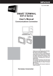
Unpacking
Check the following when removing the SLP-D10 from its package:
1. Check the model No. to make sure that you have received the product that you ordered.
2. Check the SLP-D10 for any apparent physical damage.
3. Check the contents of the package against the Package List to make sure that all accessories are included
in the package.
After unpacking, handle the SLP-D10 and its accessories taking care to prevent damage or loss of parts.
If an inconsistency is found or the package contents are not in order, immediately contact your dealer.
Name
Smart Loader Package
SLP-D10 System disk
Model No.
Qt’y
SLP-D10J50
1
–
1
CP-UM-5143
1
Japanese version
CP-UM-5143E
1
This manual.
English version
Special cable (1 set)
User’s Manual
XXXXE
P-UMNo. C
XXXXX
XX
XXXX ua
an
ser’s X
XXXX
Remarks
CD-ROM
XXXXX
XXXX
XX
XXXXX
XXXX
XX
XXXXX
XXXXX
XXXX
XX
XXXXX
XXXX
XX
XXXXX
XXXXX
XXXX
XX
XXXXX
XXXXX
XXXX
XXXXX
XXXXX
XXXXX
1
User Registration Card
iii
Enter the required particulars in
the User Registration Card and
return it to us immediately.
Otherwise, you will not receive
notification of version upgrades
and we will not be able to provide
the necessary support in
response to your inquiries.
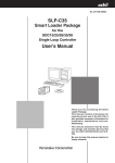
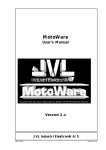
The Role of This Manual
In all, 3 manuals have been prepared for the DMC10. Read the manual according to your specific requirements.
The following lists all the manuals that accompany the DMC10 and gives a brief outline of the manual. If you do
not have the required manual, contact Yamatake Corporation or your dealer.
CP-U
M-0123E
l
Manua
User's
WARNING
CAUTION
ING
WARN
CAUT
CP-U
M-0123E
l
Manua
User's
ION
WARNING
CAUTION
WARN
DMC10S/DMC10D Distributed Multi-channel Controller
Manual No.CP-UM-5126E
This manual is packaged with the DMC10S or DMC10D.
This manual describes only the precautions when using the DMC10S and
DMC10D, their specifications and how to wire.
DMC10E Distributed Multi-channel Controller
Manual No.CP-UM-5131E
ING
This manual is packaged with the DMC10E.
CAUT
ION
XXXXE
P-UMNo . C
XXXXX
XX
XXXX ua
an
ser’s X
XXXX
This manual describes only the precautions when using the DMC10E, its
specifications and how to wire.
DMC10D Distributed Multi-channel Controller and SLP-D10
Smart Loader Package
Manual No.CP-UM-5143E
This manual.
XX
XXXX
XXXX
XXXX
XXX
XXXX
XXXX
XXX
XXX XX
XXXX
XXXX
XXX
XXX XX
XXXX
XXXX
XXX
XXXXX
XXXX
XXXX
XXX
XXX XX
XXXX
XXXX
XXX XX
This manual is supplied with the Smart Loader Package SLP-D10 system
disk.
This manual describes the product body and the exclusive SLP-D10.
This manual describes an outline of the DMC10, how to install the DMC10
for building it into instrumentation, how to wire, maintenance and
inspection, how to remedy trouble that may occur, function specifications,
how to install the Smart Loader Package SLP-D10, operations on the
personal computer, each of the functions and how to setup.
iv
Organization of This User’s Manual
This manual is organized as follows:
Chapter 1. INTRODUCTION
This chapter describes a brief outline of the DMC10 and the product model
numbers.
Chapter 2. NAMES & FUNCTIONS OF PARTS
This chapter describes the names and functions of parts on the DMC10.
Chapter 3. INSTALLATION
This chapter describes installation sites for the DMC10 and how to install
the DMC10.
Chapter 4. WIRING
This chapter describes how to wire the DMC10, how to connect the power
supply and how to connect for RS-485 communications.
Chapter 5. DEVICE CONNECTIONS & CONFIGURATION
This chapter describes the configuration of the DMC10 system and the
product model numbers.
Chapter 6. SETUP & OPERATIONS
This chapter describes overall operation methods for running the DMC10.
Chapter 7. LOADER
This chapter describes how to operate the Smart Loader Package SLPD10 exclusively for the DMC10.
Chapter 8. SETUP PARAMETERS (Common to DMC10S and DMC10D)
This chapter lists setup parameter tables and describes each function in
detail.
Chapter 9. SETUP PARAMETERS (DMC10D)
This chapter describes additional setup parameters relating to the
DMC10D only in detail.
Chapter 10. COMMUNICATIONS FUNCTIONS
This chapter describes how to communicate with a personal computer,
PLC or other host devices.
Chapter 11. MODBUS COMMUNICATIONS FUNCTIONS
This chapter describes how to communicate with a personal computer,
PLC or other host devices through MODBUS communications.
Chapter 12. ADJUSTMENT & ZENER BARRIER ADJUSTMENT
This chapter describes how to adjust the DMC10 and the adjustment
procedure.
Chapter 13. TROUBLESHOOTING
This chapter describes how to find the cause of trouble that occurs when
using the DMC10 and how to remedy trouble.
Chapter 14. SPECIFICATIONS
This chapter describes the general specifications, performance
specifications and external dimensions of the DMC10.
Appendix
This appendix provides advice for methods of use.
v
Contents
SAFETY PRECAUTIONS
Unpacking
The Role of This Manual
Organization of This User’s Manual
Conventions Used in This Manual
Chapter 1. INTRODUCTION
■ Features.......................................................................................................1-1
■ Model Selection Guide ...............................................................................1-2
Chapter 2. NAMES & FUNCTIONS OF PARTS
■ Body.............................................................................................................2-1
■ Base .............................................................................................................2-2
Chapter 3. INSTALLATION
■
■
■
■
Mounting Locations....................................................................................3-1
Linking Modules .........................................................................................3-1
Installation Procedure ................................................................................3-1
Mounting the Body on the Base................................................................3-2
Chapter 4. WIRING
■
■
■
■
■
Wiring...........................................................................................................4-1
Wiring Precautions .....................................................................................4-4
Connecting the Power Supply...................................................................4-6
Connecting for CPL Communications......................................................4-6
Connecting to the SSR...............................................................................4-7
Chapter 5. DEVICE CONNECTIONS & CONFIGURATION
■
■
■
■
Number of Connected Units ......................................................................5-1
Setting the Device Address .......................................................................5-2
Configuration When Combined With the CMC10 ....................................5-3
Layout of Event Output Module DMC10E.................................................5-4
Chapter 6. SETUP & OPERATIONS
■ Overall Operation Procedure.....................................................................6-1
■ Setup Method ..............................................................................................6-1
Chapter 7. LOADER
7-1
7-2
Introduction ......................................................................................................7-1
■ Loader Functions........................................................................................7-1
■ System Operating Environment ................................................................7-2
Installing, Starting up and Quitting the Software Package..........................7-3
■ Installation...................................................................................................7-3
■ Device Driver Installation for USB Loader Cable.....................................7-6
■ Starting Up SLP-D10.................................................................................7-10
vi
7-3
7-4
■ Quitting SLP-D10 ......................................................................................7-10
Setup Function...............................................................................................7-11
■ Outline of Setup Function........................................................................7-11
■ Screen Explanations ................................................................................7-11
■ Operation Procedure ................................................................................7-13
Monitor Function ...........................................................................................7-17
■ Outline .......................................................................................................7-17
■ Screen Explanations ................................................................................7-18
■ How to Operate the Numeric Monitor Screen ........................................7-19
■ How to Operate the Trend Monitor..........................................................7-21
Chapter 8. SETUP PARAMETERS (Common to DMC10S and DMC10D)
8-1
8-2
8-3
8-4
8-5
List of Setup Parameters ................................................................................8-1
■ Basic Functions ..........................................................................................8-1
■ Option Functions ........................................................................................8-3
Explanation of Basic Functions .....................................................................8-5
■ PV Input .......................................................................................................8-5
■ Control Output ............................................................................................8-8
■ SP and Control Parameters .....................................................................8-12
■ Communications.......................................................................................8-13
■ Other ..........................................................................................................8-14
Detailed Explanation of Option Functions ..................................................8-16
■ Event Output .............................................................................................8-16
■ Current Transformer Input.......................................................................8-25
■ External Switch Input ...............................................................................8-26
■ Auxiliary Output (current output)............................................................8-29
Event Output Special Operation...................................................................8-30
■ Setup Parameters (only for event output special operation) ...............8-30
■ Detailed Explanation ................................................................................8-31
External Switch Input Special Operation.....................................................8-33
■ Setup Parameters (only external switch input special operations) .....8-33
■ Detailed Explanation ................................................................................8-33
Chapter 9. SETUP PARAMETERS (DMC10D)
9-1
9-2
Outline of the Advanced Functions ...............................................................9-1
■ PV Input .......................................................................................................9-1
■ Control Output ............................................................................................9-1
Detailed Explanation of Basic Functions ......................................................9-3
■ Heat/Cool Output Assignments.................................................................9-3
■ Inter-channel Deviation Control ................................................................9-4
■ Control by Remote SP................................................................................9-5
■ Position Proportional Control ...................................................................9-6
■ Time Proportional Power Saving Mode ..................................................9-11
■ MV Branch Control ...................................................................................9-14
Chapter 10. COMMUNICATIONS FUNCTIONS
10-1 Outline of Communications ..........................................................................10-1
vii
■ Features.....................................................................................................10-1
■ Defaults......................................................................................................10-1
■ Communications Procedures..................................................................10-2
10-2 Message Structure.........................................................................................10-3
■ Message Structure....................................................................................10-3
■ Data Link Layer .........................................................................................10-3
■ Application Layer......................................................................................10-5
10-3 Description of Commands ............................................................................10-6
■ Read Continuous Data Command (RS command) ................................10-6
■ Write Continuous Data Command (WS command) ...............................10-7
■ Read Continuous Fixed Length Data Command (RD command).........10-8
■ Write Continuous Fixed Length Data Command (WD command)........10-9
■ Read Fixed Length Random Data Command (RU command) ............10-10
■ Write Fixed Length Random Data Command (WU command) ...........10-11
10-4 Definition of Word Addresses ....................................................................10-12
10-5 How Numerical Values Are Expressed in the Application Layer ............10-13
10-6 List of Status Codes ....................................................................................10-14
10-7 Reception and Transmission Timing .........................................................10-15
■ Timing Specifications for Instruction and Response Message .........10-15
■ RS-485 Driver Control Timing Specifications ......................................10-15
10-8 List of All Communications Parameters (in RAM address order) ...........10-16
■ Word Address Data ................................................................................10-16
■ Bit Information Data ...............................................................................10-30
10-9 Detail Explanation on Communication Conditions ..................................10-39
■ Write Conditions .....................................................................................10-39
■ Write Range.............................................................................................10-40
■ Constant Write Inhibit ............................................................................10-41
10-10 Cautions When Making Communications Programs for the Master Station ...10-42
Chapter 11. MODBUS COMMUNICATIONS FUNCTIONS
11-1 Outline of Communications ..........................................................................11-1
■ Features.....................................................................................................11-1
■ Initial Setting .............................................................................................11-1
■ Communications Procedures..................................................................11-1
11-2 Message Structure.........................................................................................11-2
■ Message Structure....................................................................................11-2
■ Transmission Message ............................................................................11-4
■ Response Time .........................................................................................11-4
■ Other Specifications.................................................................................11-4
11-3 Description of Commands ............................................................................11-5
■ RTU Encoding ...........................................................................................11-5
■ ASCII Encoding.........................................................................................11-6
Chapter 12. ADJUSTMENT & ZENER BARRIER ADJUSTMENT
■
■
■
■
Precautions before Adjustment ..............................................................12-1
Measurement Equipment Required for Adjustment..............................12-1
Adjustment Procedure .............................................................................12-1
About Zener Barrier Adjustment .............................................................12-5
viii
Chapter 13. TROUBLESHOOTING
■
■
■
■
■
■
How to Use the LEDs on the Front Panel When Checking Alarms......13-1
PV Input Related Trouble .........................................................................13-2
Body Alarms Related Trouble .................................................................13-2
Loader Communications Related Trouble .............................................13-3
Host Communications Related Trouble .................................................13-3
Control Related Trouble...........................................................................13-4
Chapter 14. SPECIFICATIONS
14-1 General Specifications ..................................................................................14-1
■ Environmental Conditions .......................................................................14-1
14-2 Performance Specifications .........................................................................14-2
■ PV Input .....................................................................................................14-2
■ Isolation Between Inputs and Outputs ...................................................14-6
■ External Dimensions ................................................................................14-6
Appendix
1. Advice on Control Constants ........................................................................App.-1
■ ON/OFF Control ....................................................................................App.-1
■ Control by Self-tuning ..........................................................................App.-1
■ Control by PID Fixed Values................................................................App.-2
2. Advice on Events ............................................................................................App.-3
3. Event Output Special Operation....................................................................App.-5
■ Internal Structure of Event Output Special Operation ......................App.-5
■ Block Diagram of Output Special Operation......................................App.-6
■ Operating Procedures for Event Output Special Operation .............App.-7
4. External Switch Input Special Operation....................................................App.-10
■ Internal Structure of External Switch Input Special
Operation.............................................................................................App.-10
■ Operating Procedures for RSW Input Special Operation ...............App.-12
■ Sample Applications Combining the Event Output Special ...........App.-14
Operation and the RSW Special Operation
5. Settings When Heat/Cool Control Is Used..................................................App.-15
■ Setting Procedures.............................................................................App.-15
6. Settings When Remote SP Is Used .............................................................App.-16
■ Setting Procedures.............................................................................App.-16
7. Settings When Inter-Channel Deviation Control Is Used ..........................App.-17
■ Setting Procedures.............................................................................App.-17
ix
Conventions Used in This Manual
The following conventions are used in this manual:
Handling Precautions
: Handling Precautions indicate items that the user should pay attention
to when handling the DMC10.
Note
: Notes indicate useful information that the user might benefit by
knowing.
(1), (2), (3)
: The numbers with the parenthesis indicate steps in a sequence or
indicate corresponding parts in an explanation.
[Open] button
: Indicates a selection button in screens displayed on the personal
computer.
: Indicates icon buttons displayed on the personal computer.
[SLP-D10.exe],
[Printing],
[Open file]
: Indicate messages and menus displayed on the personal computer.
: Indicates the result of an operation, details displayed on the personal
computer or devices, or the state of a device after an operation.
[Tab] key, [F4] key
: Indicates keys on the keyboard.
[Ctrl] + [T] key
: Indicates the operation of pressing the [T] key with the [Ctrl] key on the
keyboard held down.
– (minus) to + (plus)
: This manual expresses numerical value ranges using – (minus) and +
(plus), for example as –10 to +100, when expressing a range starting
with a minus value.
Ranges are not expressed using a + (plus) when the range starts from
a plus value for example as 0 to 1000.
Data specified in transmission and reception in communications need
not be prefixed with + (plus). An error occurs if data is prefixed with the
+ (plus) symbol.
x
Chapter 1.
INTRODUCTION
■ Features
• This modular is provided with 2-loop or 4-loop control functions on each single
unit.
• Input types are thermocouples (K, J, E, T, R, S, DIN U, DIN L), resistance
temperature detector (Pt100, JPt100), current signals (4 to 20mAdc), and voltage
signals (0 to 1Vdc, 0 to 5Vdc, 1 to 5Vdc). Each of these input types can be
designated to each channel. This allows different inputs to be combined on a
single controller.
Each of the channels is isolated, eliminating worry of trouble caused by
rerouting circuits.
• Control output types are relay and voltage pulse, and control types are ON/OFF
control, self-tuning control and control by fixed PID.
• Optional functions for the 2-channel model include current transformer input
used for the heater line break alarm; upper/lower limit alarm or heater line break
alarm; event output that can be used as a delay timer; RUN/READY or
AUTO/MANUAL mode switching; external switch input that can be used as a
function for switching four setting values; and current output (AUX) that
enables input of PV value trends to a recorder. Select the option to suit your
particular control requirements. (Optional functions cannot be added on to 4channel models.)
• Use of the event output module (sold separately) enables use of event output
even on 4-channel modules.
• Connection of the link connector on the side of the DMC10 and relay terminals
provided on the base enable connection to up to 15 modules.
• The DMC10 has not display or setup unit. This allows it to be designed in a
compact size (30mm (W) x 100mm (H) x 110mm (D)).
• The DMC10 can be mounted on DIN rail or screw-mounted on walls. This
facilitates mounting on panels or instrumentation.
• The DMC10 Smart Loader Package (sold separately) is supported on PC/AT
compatible personal computers (Windows OS).
• Parameters can be read and written easily on the DMC10 Smart Loader Package
(sold separately).
In addition to setting the table format, operations while the DMC10 is running
and monitoring of the control state on the trend screen are possible. This enables
operation of the DMC10 without the need for a program on the host device.
• With the advanced function model DMC10D, heat/cool control, inter-channel
deviation control, remote SP input, position proportional control and power
saving functions can also be used in addition to the above functions.
• The DMC10 conforms to IEC directives, and has acquired CE marking.
(applicable standard: EN61010-1, EN50081-2, EN50082-2)
When the CE standard is to be acquired on the instrumentation, use a third-party
24Vdc power supply that has CE marking.
1-1
Chapter 1. INTRODUCTION
■ Model Selection Guide
● Configuration of DMC10S, DMC10D model numbers
Basic
Number of Wiring
Model No. Channels Method
DMC10S
DMC10D
2
4
T
C
Control
Output
Options
Additional
Processing
R
V
00
01
02
03
04
05
06
00
D0
Y0
Specifications
Standard model *1
Advanced function model
2-channel input *2
4-channel input *3
Terminal wiring
Connector wiring
Relay output
Voltage pulse output (for SSR drive)
None
2 CT inputs, 4 event relay outputs
2 CT inputs, 4 external switch inputs
2 AUX outputs, 4 event relay outputs
2 AUX outputs, 4 external switch inputs
2 CT inputs, 2 event relay outputs, 2 event voltage outputs
2 CT inputs, 2 external switch inputs, 2 event voltage outputs
None
Inspection Certificate provided
Complying with the traceability certification
*1: When the standard model is selected, you cannot select options “05” and “06”.
*2: When 2-channel input is selected, option “00” cannot be selected.
*3: When 4-channel input is selected, option “00” is fixed.
● List of DMC10 related products
Specifications
Model No.
DMC10E4CR0000 Event output module (4-channel relay output)
Smart Loader package for DMC10 (including special cable)
SLP-D10J50
Connector set (pack of 4, MSTB2, 5/5-STF-5, 08AU made by
81440792-001
Phoenix Contact)
For Distributed Multi-Channel Controller DMC10
SDU10T0100
● List of CMC10 related products
Specifications
Model No.
CMC10ACL1A000 Communications Controller CC-Link/CPL converter
CMC10BCP1A000 Communications Controller CPL/CPL Converter
Communication Controller
CMC10G
(PLC/Controller Converter)
CMC10L001A000 RS-232C/RS-485 converter
Smart Loader package for CMC10B (including special cable)
SLP-CM1E20
Terminating resister (110Ω, 2 p’ces) for CMC10A
81446717-001 *
Terminating resister (130Ω, 2 p’ces) for CMC10A
81446717-002 *
AC adapter for CMC10L
81446748-001
Connector set (pack of 4, MSTB2, 5/5-STF-5, 08AU made by
81440792-001
Phoenix Contact)
*: Connect this terminating resistor to both of the units that are at either end of the
CC-Link. However, please note that the specifications of the terminating resistor
vary depending on the cable used for the CC-Link. For more information on the
terminating resistor, refer to:
• Mitsubishi Electric CC-Link System Master Local Unit User’s Manual
(currently being revised)
• Mitsubishi Sequencer Technical News (No.PLC-D-330).
1-2
Chapter 2.
NAMES & FUNCTIONS OF PARTS
■ Body
● DMC10S, DMC10D
Rotary switch for device address:
Sets the address used for host
communications.
0:
Communications disabled
(factory setting)
1 to F: Communications enabled
Loader jack:
Used for connecting the special
cable packaged with the DMC10
Smart Loader Package SLPD10J20 for performing setup and
monitoring on the Loader.
POWER lamp:
Lights when power is being supplied
(factory setting).
Blinks for approx. 10 seconds for
initialization after the power is
turned ON.
Communications is not possible
during initialization.
Various states can be monitored
according to the lamp setting.
● DMC10E
EV1 to EV4 operation lamps:
Light when the relay contact of the target
channel inside the module turns ON.
Note
The compatible connector for the DMC10S and DMC10D connector wiring
models and the DMC10E is part No. 81440792-001 (4 pc’s/set).
This is an equivalent product of MSTB2, 5/5-STF-5, 08AU made by Phoenix
Contact.
2-1
Chapter 2. NAMES & FUNCTIONS OF PARTS
■ Base
Mounting holes (2 locations):
For securing the base with
M3 screws
Communications disconnection switch:
Used for disabling CPL
communications with devices linked
on the left side
(factory setting: CONNECT
)
(linked state)
Lever:
For securing the body
Side connector
Power supply terminal
Mounting hole
DIN rail locking tab:
Used for locking on a
DIN rail
2-2
CPL communications terminal:
3-lead RS-485 connector terminal
Chapter 3.
INSTALLATION
CAUTION
Use the DMC10 within the operating ranges (temperature, humidity, vibration,
shock, mounting direction, atmosphere, etc.) recommended in the
specifications.
Failure to do so might cause fire or faulty operation.
Do not block ventilation holes.
Doing so might cause fire or faulty operation.
■ Mounting Locations
Avoid installing the DMC10 in the following locations:
• Locations subject to low and high temperature and humidity exceeding the
specified ranges
• Locations subject to corrosive gases such as sulfide gases
• Locations subject to dust or oil smoke
• Locations subject to direct sunlight, wind or rain
• Locations subject to vibration or shock exceeding the specified ranges
• Locations under high-voltage lines and near sources of electrical noise such as
welders
• Locations within 15 meters of high-voltage ignition equipment such as boilers
• Locations where magnetic fields are generated
• Locations near flammable liquid or steam
■ Linking Modules
The DMC10 can be linked with other modules by the connectors on the left and
right of the base. Modules must be linked before the DMC10 is mounted on the
DIN rail or mounted by screws. By linking modules together, the power supply of
each module and CPL communications are connected, eliminating the need for
wiring. CPL communications can be disconnected by the communications
disconnection switch on the base.
■ Installation Procedure
The DMC10 can be mounted in either of two ways, by mounting its base by
screws or by securing on a DIN rail.
● Mount each DMC10 module vertically as in the figure below.
Top
4
ADR 0
LOADER
SD
2 3 4
1
0
5
9
8 76
1
0
4
LDR
ADR 0
PWR
4
LDR
ADR 0
8
C
CH3
CH1
LDR
8
PWR
C
PWR
CH1
power
21
16
22
SD
2
RD
HOST CMC
CMC ADDRESS
2 3 4
1
0
5
9
8 76
8
C
CH3
power
17
23
18
24
19
25
20
21
16
22
17
23
18
24
19
25
20
HOST CMC
B.RATE
Front
CH4
CMC10
11
12
RD
CMC LOCAL
11
12
13
14
15
SD
21
22
23
13
14
ERR
24
25
15
CH4
CH2
21
22
23
24
25
21
22
23
24
25
CH2
21
22
23
24
25
RESET
CMC10
DMC10
DMC10
Handling Precautions
• Mount the DMC10 modules in the same horizontal plane. Deviation
from the horizontal should not exceed the amount stated in the
specifications.
3-1
Chapter 3. INSTALLATION
● Do not mount as shown below.
Front
Front
SD
power
11
12
11
power
LOADER
HOST CMC
ADR 0
21
ERR
14
24
24
13
23
RD
11
SD
22
22
21
21
24
24
23
23
22
22
21
21
CH2
CH1
C
CH3
CMC ADDRESS
1
0
SD
RD
2
2 3 4
1
0
5
9
8 76
SD
20
25
19
24
18
23
17
22
16
21
20
25
19
24
18
23
LDR
2 3 4
1
0
5
9
8 76
8
HOST CMC
HOST CMC
B.RATE
4
17
22
PWR
CH2
ADR 0
C
CH4
CMC LOCAL
20
19
18
17
16
CH4
CH1
PWR
LDR
8
CH2
25
24
23
22
21
DMC10
CMC LOCAL
23
12
4
C
CH3
CH4
11
25
ADR 0
21
25
24
23
22
12
DMC10
25
16
20
19
18
17
21
25
24
23
22
13
25
25
CH1
PWR
LDR
8
CH2
14
DMC10
CMC10
4
C
CH3
CH4
RESET
25
24
23
22
21
25
24
23
22
DMC10
15
SD
RD
21
25
24
23
22
15
2
2 3 4
1
0
5
9
8 76
1
0
2 3 4
1
0
5
9
8 76
HOST CMC
B.RATE
SD
RD
ERR
CMC10
RESET
CMC10
12
13
14
15
CMC ADDRESS
13
14
15
CMC10
Top
16
21
power
CH1
C
CH3
power
LOADER
PWR
8
ADR 0
4
PWR
8
ADR 0
LDR
4
LDR
C
8
ADR 0
4
PWR
LDR
Top
● When mounting the base by screws
Secure the two mounting holes on the base by M3 screws.
Unit: mm
(30)
+0.9
30+0.3
M3
10–0.2
78.5–0.2
(100)
5
5
● When securing on a DIN rail
Secure the DMC10 on the DIN rail, fully draw out the DIN rail locking tab and
hook the base onto the DIN rail. Next, push the DIN rail locking tab upwards until
you hear it click into place.
■ Mounting the Body on the Base
Fit the hook into the base and push the body into the base until you until you hear
it click into place. To remove the body from the base, pull the body towards you
while pressing down the lever.
Lever
Hook
3-2
Chapter 4.
WIRING
CAUTION
Before wiring or installing the DMC10, be sure to turn the power OFF.
Failure to do so might cause faulty operation.
Wire the DMC10 properly according to predetermined standards. Also wire
the DMC10 using designated power supply according to recognized
installation methods.
Failure to do so might cause electric shock, fire or faulty operation.
Firmly tighten the terminal screws at the torque listed in the specifications.
Insufficient tightening of terminal screws might cause fire.
Do not use unused terminals on the DMC10 as relay terminals.
Doing so might cause electric shock, fire or faulty operation.
■ Wiring
● 2-channel model
4
ADR 0
LDR
8
PWR
C
CT input (CH1)
AUX output (CH1)
21
CT
21 +
CT1
22
22
External switch input
RSW1
23
RSW
1,2
RSW2
24
CT input (CH2)
28
29
12
23
13
24
14
25
+ AUX2
27 Event voltage output Event relay output
(CH3/4)
(CH3/4)
External switch input
(CH3/4)
RSW4
22
Event 3 28
RSW
3,4
Event 4
29
30
30
+
+
-
11
11
12
12
26
16
27
17
RTD input (CH1)
+
14 B
PV1
14
15
28
18
EV3,4
15 A
30
19
30
mA
13
14
V
15
+
+
Relay output (CH2) Voltage output (CH2)
OUT2
29
DC voltage/DC
current input (CH1)
13 C
16
16
17
17
+
-
Thermocouple input
(CH2)
RTD input (CH2)
+
19 B
18
Event 3 28
Event 4
29
+
-
Thermocouple input
(CH1)
15
26
CT2
27
RSW3
EV1,2
AUX output (CH2)
26
CT
OUT1
13
25
25
Relay output (CH1) Voltage output (CH1)
11
AUX1
-
Event relay output
(CH1/2)
Event 1 23
Event 2
24
(CH1/2)
DMC10
21
PV2
19
20
20
DC voltage/DC
current input (CH2)
18 C
20 A
mA
18
19
V
20
+
+
Note: The terminal numbers are the same on the connector model.
● 4-channel model
4
ADR 0
Thermocouple input
(CH3)
21
22
+
-
23
RTD input (CH3)
DC voltage/DC
current input (CH3)
21 A
22 B
23 C
V
21
22
mA
23
+
+
21
24
25
25
Thermocouple input
(CH4)
26
27
28
+
-
28 C
PV3
DC voltage/DC
current input (CH4)
V
26
27
mA
28
+
+
29
30
30
+
22
12
23
13
24
14
25
15
26
16
27
17
28
18
11
12
Thermocouple input
RTD input (CH1)
(CH1)
PV1
14
15
29
19
30
20
DC voltage/DC
current input (CH1)
13 C
+
14 B
15 A
mA
13
14
V
15
+
+
Relay output (CH2) Voltage output (CH2)
16
16
17
17
Thermocouple input
(CH2)
18
OUT4
+
-
11
12
OUT2
PV4
Relay output (CH4) Voltage output (CH4)
29
Relay output (CH1) Voltage output (CH1)
11
OUT3
26 A
27 B
DMC10
13
+
RTD input (CH4)
PWR
OUT1
Relay output (CH3) Voltage output (CH3)
24
LDR
8
C
PV2
19
20
+
-
RTD input (CH2)
DC voltage/DC
current input (CH2)
18 C
+
19 B
20 A
mA
18
19
V
20
+
+
Note: The terminal numbers are the same on the connector model.
4-1
Chapter 4. WIRING
● Heat/cool model (2-channel model)
In the heat/cool control, it is necessary to set up the outputs of each loop. The
settings vary according to the model. There is no heat/cool model among the 4LDR
ADR
channel models.
PWR
The relationship between the settings and the output specifications is shown
21
11
AUX1
OUT1 below.
22
12
The settings shown below become effective only after collectively being written
by the loader.
23
13
4
0
8
C
DMC10
24
14
25
15
26
16
27
17
28
18
29
19
30
20
Setting
0
OUT2
AUX2
EV3,4
PV1
1
2
PV2
3
4
5
6
7
8
9
10
Operating
terminal type
Heat: Relay
Cool: Relay
Heat: Voltage
Cool: Relay
Heat: Relay
Cool: Voltage
Heat: Voltage
Cool: Relay
Heat: Relay
Cool: Voltage
Heat: Voltage
Cool: Voltage
Heat: Relay
Cool: Current
Heat: Current
Cool: Relay
Heat: Voltage
Cool: Current
Heat: Current
Cool: Voltage
Heat: Current
Cool: Current
CH1
CH2
output port output port
OUT1
OUT2
EV3
EV4
OUT1
OUT2
EV3
EV4
EV3
EV4
OUT1
OUT2
EV3
EV4
OUT1
OUT2
OUT1
OUT2
EV3
EV4
OUT1
OUT2
EV3
EV4
OUT1
OUT2
AUX1
AUX2
AUX1
AUX2
OUT1
OUT2
OUT1
OUT2
AUX1
AUX2
AUX1
AUX2
OUT1
OUT2
AUX1
–
AUX2
–
Available models
• DMC10D2XR01X0
• DMC10D2XR03X0
• DMC10D2XV01X0
• DMC10D2XV03X0
• DMC10D2XV01X0
• DMC10D2XV03X0
• DMC10D2XR05X0
• DMC10D2XR06X0
• DMC10D2XR05X0
• DMC10D2XR05X0
• DMC10D2XV05X0
• DMC10D2XV06X0
• DMC10D2XR03X0
• DMC10D2XR04X0
• DMC10D2XR03X0
• DMC10D2XR04X0
• DMC10D2XV03X0
• DMC10D2XV04X0
• DMC10D2XV03X0
• DMC10D2XV04X0
• DMC10D2XX03X0
• DMC10D2XX04X0
Remarks
One-loop
control only
Note: The Xs in the numbers of the available models indicate that any applicable
functional code is acceptable.
4-2
Chapter 4. WIRING
● Position proportional model (2-channel model)
The position proportional control function allows you to use the DMC10 as a
LDR
ADR
position proportional controller for one channel or two channels.
PWR
The output terminal assignment shown below becomes effective only after
4
0
8
C
DMC10
21
11
22
12
23
13
24
14
25
15
26
16
27
17
28
18
29
19
30
20
OUT1
PV1
OUT2
EV3,4
PV2
Available models Position proportional PV Feedback OPEN CLOSE Remarks
CH No.
input
DMC10D2XRXXX
CH1
PV1
PV2
OUT1 OUT2 With
CH2
–
–
–
–
feedback
DMC10D2XR01X
CH1
PV1
–
OUT1 OUT2 Without
DMC10D2XR03X
CH2
PV2
–
EV3
EV4 feedback
collectively being written by the loader.
Note: The Xs in the numbers of the available models indicate that any applicable
functional code is acceptable.
Handling Precautions
• Make sure to use the auxiliary relay for driving the motor.
• When the DMC10 is set so that the position proportional control is
used with feedback, the PV input channel is used for feedback input.
(See above.)
Motor
Y
A
DMC
T
B
PV input
G
C
• Connect the motor as follows:
• When the position proportional channel 2 is not used, it is also
allowed to use EV3 and EV4 as the normal EVENT terminals by
changing the event special output operation (assignment of output
terminals).
• When the position proportional channel 2 is not used, it is also
allowed to select the model number DMC10D2XRXXX.
• It is not allowed to change the feedback input channel.
● Position proportional model (4-channel model)
4
ADR 0
LDR
8
C
PWR
DMC10
21
11
22
12
23
13
24
14
25
15
26
16
27
17
28
18
29
19
30
20
OUT1
PV3
PV1
OUT3
Available models Position proportional
control CH No.
DMC10D4XRXXX
CH1
CH2
DMC10D4XRXXX
CH1
CH2
PV
PV1
PV2
PV1
PV2
Feedback
input
PV3
PV4
–
–
OPEN CLOSE Remarks
OUT1
OUT2
OUT1
OUT2
OUT3
OUT4
OUT3
OUT4
With
feedback
Without
feedback
Note: The Xs in the numbers of the available models indicate that any applicable
functional code is acceptable.
OUT2
PV4
PV2
OUT4
4-3
Chapter 4. WIRING
● DMC10E
Extended event (CH1)
11
11
12
NO
12
NC
13
13
14
Extended event (CH2)
15
14
15
Extended event (CH3)
16
16
17
18
NO
17
NC
18
19
20
Extended event (CH4)
19
20
NO: Normally Open (open)
NC: Normally Close (close)
■ Wiring Precautions
CAUTION
The DMC10 will not function for about ten seconds after turning the power
ON. Pay attention to this when using the relay output from the DMC10 as an
interlock signal.
• Check the model number of the controller and terminal numbers on the label on
the side of the controller to prevent any wiring errors.
• Use crimped terminals for M3.5 screws to connect terminals.
• Prevent crimped terminals from coming into contact with adjacent terminals.
• I/O signal lines should be routed at least 50cm away from power lines. Also, do
not route I/O leads through the same distribution box or ducts.
• Before connecting in parallel to other equipment, thoroughly check the
conditions of the other equipment.
• Pass a lead wire for carrying the heater current through a current transformer.
Do not use a heater current that exceeds the allowable current described in the
specifications. Doing so might damage the DMC10.
• The controller is designed not to function for ten seconds after the controller is
turned ON. This is to allow it to stabilize. The controller then enters the Run
mode. However, allow at least 30 minutes for the controller to warm up so that
the specified accuracy is satisfied.
• When wiring is finished, check the connections for any miswiring before turning
the power ON.
4-4
Chapter 4. WIRING
● Wiring connectors (81440792-001: sold separately)
• Specifications of cable used
Lead type:
Single lead or twisted
Lead size:
0.2 to 2.5mm2 (AWG28 to 12)
Ideal exposed lead length: 7mm
7mm
• Screw tightening torque
Connector terminal:
Connector mount:
0.5 to 0.6 N·m
0.5 to 0.6 N·m
• Specifications of recommended screwdriver
We recommend using a screwdriver matched to the connector screw to
firmly fasten the cable.
Manufacturer: Phoenix Contact
Model No.:
SZS0.6 x 3.5
Note
• Crimped terminal
Generally, use a sleeve for the crimped terminal to mark each of the cables.
The following shows crimped terminals matched to this connector for
reference purposes.
Manufacturer: J.S.T Mfg Co., Ltd.
Model No.:
VTUB-1.25
(pack of 1000, w/ insulated covering, lead size: 0.25 to
1.65mm2)
VTUB-2
(pack of 1000, w/ insulated covering, lead size: 1.04 to
2.63mm2)
TUB-1.25
(pack of 1000, w/out insulated covering, lead size: 0.25 to
1.65mm2)
TUB-2
(pack of 1000, w/out insulated covering, lead size: 1.04 to
2.63mm2)
4-5
Chapter 4. WIRING
■ Connecting the Power Supply
CAUTION
Prevent the total power consumption of all linked modules from exceeding
100W.
Connect the power terminal as follows:
Power is mutually connected between linked modules.
Supply power to one of the linked modules.
No.
1
2
3
Signal
24Vdc (+)
24Vdc (–)
Do not use
1
2
3
Do not use
–
+
24Vdc
The power supply unit must be a UL approved Class 2 power supply unit or Class
2 transformer in order to apply UL.
Handling Precautions
Select a power supply that can cover the total power consumption of all
linked modules.
■ Connecting for CPL Communications
CPL communications (RS-485) is performed using a 3-lead connection.
Connect to one of the linked modules for communications.
No.
4
5
6
Signal
DA
DB
SG
Handling Precautions
• Do not connect an external terminating resistor as the DMC10 has a
built-in resistor equivalent to a terminator.
• Do not connect a terminating resistor when setting an SDC series, DCP
series or SRF series product (made by Yamatake Corporation) to the
same communications line.
• Be sure to connect SG terminals each other.
Failure to do so might cause unstable communications.
4-6
Chapter 4. WIRING
■ Connecting to the SSR
Up to 3 DMC10s can be connected in series to the main SSR.
Note, however, that connection is subject to conditions.
• When connecting to a PGM (made by Yamatake Corporation)
Number of
SSR Units
1
Connection Conditions
Remarks
External resistors of
510Ω (consumption
current 1/2W or more)
are required in series.
DMC10
Voltage +
output –
+ PGM
– SSR
How to connect to one PGM
(made by Yamatake Corporation)
Series connection
2
510
DMC10
Voltage +
output –
+ PGM
– SSR
+ PGM
••••
– SSR
Series connection
3
How to connect to two or more PGMs
(made by Yamatake Corporation)
The following shows an example of how to calculate when the DMC10 is
connected to two units of the PGM (made by Yamatake Corporation):
DMC10
R1
+
V
–
V:
R1:
R2:
VF:
+
–
PGM
R2
••••
VF
+
–
13V±5%
150Ω±5%
260Ω
1.2V
Voltage between PGM terminals =
PGM
R2
VF
(V–2 X VF)
R1+2 X R2
≈ 5.3V
X R2+VF
Allowable voltage between PGM terminals:
In the above connection, operation is possible within 3 to 6V.
4-7
Chapter 4. WIRING
• When connecting to a PGM10N/F (made by Yamatake Corporation))
Number of
SSR Units
1
Connection Conditions
Remarks
DMC10
2
Parallel connection
3
Parallel connection
(PGM10N only)
+
+
Voltage +
output –
–
SSR
••••
–
SSR
How to connect to two or more PGM10N/F
(made by Yamatake Corporation)
The following shows an example of how to calculate when the DMC10 is
connected to the PGM10N015 (made by Yamatake Corporation):
• Max. input current of SSR ≤ Allowable max. current of voltage pulse
output. This relation must be satisfied.
Since the input current is 10mA or less, 10mA X 3 units = 30mA.
This is less than the allowable max. current 30mA of voltage pulse output.
Therefore, 3 units can be driven.
• The input voltage range of SSR must be within the range of voltage
between terminals of voltage pulse output.
13V ± 5% (voltage between terminals of output) - 150Ω ± 5% (internal
resistance) X 30mA (driving current for 3 units) ≈ 7.5 to 9.5V.
This is within the input voltage range 3.5 to 30V of SSR.
Therefore, 3 units can be driven.
• When connecting to a G3PA (made by Omron Corporation)
Number of
SSR Units
1
4-8
Connection Conditions
2
Parallel connection
3
Parallel connection
Remarks
DMC10
Voltage +
output –
+ G3PA
– SSR
200Vac
••••
Load
How to connect to two or more G3PA
(made by Omron Corporation)
+ G3PA
– SSR
200Vac
Load
Chapter 5.
DEVICE CONNECTIONS & CONFIGURATION
■ Number of Connected Units
● When connecting 15 or less units
Up to 15 DMC10s can be connected directly to a single host device (personal
computer, programmable display device, PLC).
Note
The following shows a guideline of the time required for communications:
Communications time = {(number of data items per unit) x 3.3ms + 27ms} x
number of connected units
Note, however, that this value is a reference value that includes processing time on
the host (Windows98, Pentium III 800MHz) when a Yamatake host test program is
used at a transmission speed of 19200bps.
When 15 units of 4-channel model is multi-dropped under the above conditions,
and also “PV of each device=4ch X 15 units (PV amount of 60 channels)” is read
out,
• Use of Yamatake CMC10L for RS-232C/RS-485 conversion
• Communication command: RD03EA0004 (PV is read out for 4-channels on
each device)
In this case, the communication completes in approx. 600ms.
CMC10L
DMC10S
/DMC10
D
Max. 15
units
•
•
•
•
•
This value may vary considerably according to the operation content of the host
device, content of communications with the DMC10, setup and commands used.
The CMC10L is a converter for converting between RS-232C to RS-485
communications.
This converter is not required when the host device has a 3-lead RS-485
communications port.
● When connecting 16 or more units
CMC10L
CMC10B
Max. 15 un
its
DMC10S
DMC10D
RS-485
CMC10B
Max. 15 un
its
DMC10S
DMC10D
CMC10B
Max. 15 un
its
DMC10S
DMC10D
RS-485
The communications converter CMC10B (sold separately) is needed to connect
16 or more DMC10s.
Note
The CMC10B allows up to 31 DMC10s to be connected to a host device.
Handling Precautions
• The number of connected units refers to the number of units that can be
connected electrically. In this kind of connection, you must check
whether or not the transmission speed is suited to the required level in
the application. Consult a Yamatake sales agent.
• Event output module DMC10E is not included in the number of
connected units.
5-1
Chapter 5. DEVICE CONNECTIONS & CONFIGURATION
■ Setting the Device Address
The device address must be set to the DMC10 in order to use the DMC10.
Set the device address as follows:
•
When connecting 15 DMC10s directly to a single host device
Set the rotary switch for device address on the front panel to 1 to F, respectively,
and then turn the power ON again.
Handling Precautions
The same device address cannot be used. Use unique device
addresses.
•
When connecting 15 DMC10s each to a host device via multiple CMC10Bs
(1) Set the rotary switch for device address on the CMC10B to a number within
the range 1 to 99.
(2) Set the rotary switch for device address on the front panel of the DMC10 to
a value within the range 1 to F.
CMC10L
CMC10B (Set a value 1 to 99.)
CMC10B (Set a value 1 to 99.)
DMC10S/DMC10D
(Set a value 1 to F.)
DMC10S/DMC10D
(Set a value 1 to F.)
RS-485
CMC10B (Set a value 1 to 9
DMC10S/DMC10D
(Set a value 1 to F.)
RS-485
Note
The CMC10B allows up to 31 DMC10s to be connected to a host device.
Handling Precautions
• The CMC10B cannot be connected if MODBUS is used.
• Be sure to set the device address of DMC10s connected to the same
CMC10B to unique values.
• The same device address can be used when a DMC10 is connected
to different CMC10Bs.
• For details on CMC10B settings, refer to the Communications
Controller CMC10B (CPL/CPL Converter) separate Instruction
Manual, Design Manual CP-SP-1064E.
5-2
Chapter 5. DEVICE CONNECTIONS & CONFIGURATION
■ Configuration When Combined with the CMC10
● Connecting two CMC10s
Change the setting of the communications disconnection switch on the base to the
right when two CMC10Bs are linked by the side connector. Slave
communications between CMC10s are independent of this setting.
Change setting of
communications
disconnection switch to
right side.
(Example) In the following instrumentation configuration, the communications
disconnection switch on the base of only the CMC10Bs indicated in
the figure must be set to the right to isolate slave communications
with the CMC10B on the left side: This saves wiring to the power
supply.
CMC10L
CMC10B
CMC10B
● Position of CMC10B
The CMC10B can be positioned anywhere within a linked group.
CMC10B
CMC10B
5-3
Chapter 5. DEVICE CONNECTIONS & CONFIGURATION
■ Layout of Event Output Module DMC10E
Only one event output module DMC10E can be used within a group linked by
connectors.
When the connection is made by wiring from the bases without using the side
connectors as shown below, each group is independent and a new event output
module can be used.
● Position of event output module
DMC10E
DMC10E
RS-485 communications
DMC10E
RS-485 communications
DMC10E
DMC10E
Two or more units cannot be
used in the same group.
The event output module DMC10E can be positioned anywhere within a linked
group.
DMC10E
5-4
DMC10E
Chapter 6.
SETUP & OPERATIONS
■ Overall Operation Procedure
The following operation and preparations are required to use the DMC10:
Step1
Determine the values of the DMC10’s parameters for
running from the user’s application.
Step2
Enter the setup parameters for running to the
communications device.
(computer, sequencer, PLC, etc.)
Step3
Write the setup parameters to the DMC10 from the
communications device.
(The DMC10 must be mounted on the panel and wired
beforehand.)
Step4
Start running and tune the control constants.
(This step is sometimes not required when self-tuning is
used.)
Note
The exclusive Smart Loader Package SLP-D10 is available for the DMC10.
This loader allows you to easily set up data before you start running the DMC10,
enter setup parameters for running, monitor operation while the DMC10 is
running and changing the settings.
When the exclusive Smart Loader Package is not used, the user must make the
program for the DMC10.
The Smart Loader Package drastically reduces the load in creating and debugging
programs, reduces trouble in setup and monitoring, and reduce the size of the
program on the host communications device.
■ Setup Method
There are three ways of setting up the DMC10:
1. When the exclusive Smart Loader Package is used to set up the DMC10 or
monitor the DMC10 while it is running:
Proceed to “Chapter 7. LOADER.”
2. When a user program is used to set up the DMC10 or monitor the DMC10
while it is running:
Proceed to “Chapter 10. COMMUNICATIONS FUNCTIONS.”
3. When the exclusive Smart Loader Package is used to set the required setup
parameters before running the DMC10, and the user program is used to set
parameters such as SP (set point) or PV (process variable) that required
monitoring or changing while the DMC10 is running:
Read both “Chapter 7. LOADER” and “Chapter 10. COMMUNICATIONS
FUNCTIONS.”
6-1
Chapter 7.
7-1
LOADER
Introduction
■ Loader Functions
The SLP-D10 has three functions:
• Setup function
• Monitor function
• Adjustment function
● Setup function
This function is for setting up parameters required for running the DMC10 on the
personal computer and writing (setting) them to the DMC10. Up to about 70 types
of parameters can be set.
● Monitor function
After the setup parameters have been written to the DMC10, changes to and
tuning of control constants while the DMC10 is running, switching of modes
(RUN/READY, AUTO/MANUAL, etc.), run state and alarm occurrence can be
checked.
The run state can also be checked on the Trend screen, and sampled data can be
output in CSV format so that it can be handled in third-party spreadsheet software
such as Microsoft Excel.
Handling Precautions
The monitor target is limited to only one unit when the loader jack on
the front panel is used for performing monitoring.
● Adjustment function
This function is used when the user adjusting DMC10 input.
For details on the adjustment function, see “Chapter 12. ADJUSTMENT &
ZENER BARRIER ADJUSTMENT.”
Handling Precautions
When the adjustment function is used, adjustment value stored on the
DMC10 so far are discarded. (When this function is used for the first
time, the DMC10’s default adjustment values are discarded.) Pay
sufficient attention to this when using this function.
7-1
Chapter 7. LOADER
■ System Operating Environment
The following system environment is required for using the SLP-D10:
● Hardware
Item
Personal
Computer
Description
PC/AT compatible with a Pentium chip or
higher
32M byte or more
Memory
Windows98/Me/2000 Professional/
Operating system
XP Home edition/XP Professional
1 port or more
USB port
Application Spreadsheet software Excel, etc. (when using CSV files)
Internet Explorer, etc. (when using HTML
Web browser
files)
Windows compatible display connectable to
Peripheral Display
or built-into computer body
Devices
Hard disk with at least 40M byte of free
Hard disk drive
space
1 drive or more
CD-ROM drive
Windows compatible mouse or equivalent
Pointing device
device
Target model
Handling Precautions
• Before starting up SLP-D10, quit all other applications.
If you start up SLP-D10 while another application is running, SLP-D10
may not function.
Also, set the power save setting, infra-red communications and screen
saver to OFF.
• Make sure that the [Decimal symbol] has been set to " . " for [Control
Panel]−[Regional Settings]−[Number]. If it has been set to other
character, the loader cannot correctly function.
● Hardware configuration
SLP-D10
DMC10
4
ADR 0
PWR
CH1
21
16
22
17
23
19
25
20
CH4
22
23
24
25
Communications
Reading/Saving
18
24
21
Hard disk
LDR
8
C
CH3
CH2
Special cable (provided)
21
22
23
24
25
DMC10
Note
Personal computer used for confirmation of Manufacturer
Dell
operating environment.
Dell
Fujitsu
7-2
Model No.
Optiplex Gxi5200
Optiplex GX5166
FMV-5166T3
Chapter 7. LOADER
7-2
Installing, Starting up and Quitting the Software Package
■ Installation
This section describes how to install the SLP-D10 on a personal computer.
Handling Precautions
If you start up the Installer while another application is running, the Installer
may malfunction.
Remove other resident applications from their directories before starting up
the Installer.
The SLP-D10 sometimes cannot be started up depending on the
combination of other applications and drivers.
For details on Windows and personal computer settings, refer to the User’s
Manuals provided with Windows and the personal computer.
● Installing SLP-D10
(1) Put the CD in the CD-ROM drive of your personal computer.
>> The installation program starts automatically and the following screen
appears:
(2) Only when the SLP-D10 of old version has been installed, click [OK] to delete
the old SLP-D10.
The following screen appears:
(3) Click [Next>].
7-3
Chapter 7. LOADER
Note
To change the installation destination directory, click [Browse...].
(4) Click [Next>].
The following screen appears.
(5) Click [Next>].
Note
To change the group, enter the new group name.
7-4
Chapter 7. LOADER
(6) Click [Next>].
(7) Click [Finish].
When installation ends normally, the following screen appears:
7-5
Chapter 7. LOADER
■ Device Driver Installation for USB Loader Cable
A device driver must be installed before using the USB loader cable.
Follow the procedure below to install the device driver.
● Installing the device driver
Handling Precautions
• Be sure to follow the procedure below when installing the device driver.
The USB cable may not be recognized if the procedure is not followed. If
the cable is not recognized, uninstall the driver and then install it again.
• Administrator privileges on the computer are required for driver
installation. Installation should be done by the administrator or by a user
who belongs to the administrator group.
The USB loader cable is supported on Windows 98/Me/2000/XP (32 bit
type). It is not supported on 64-bit Windows XP, or on Windows 95,
Windows NT, MS-DOS or PC-DOS.
• If there are multiple USB ports, connect the USB loader cable to the
same port every time. If it is connected to a different port, there is a
chance that driver installation may be required again.
1. Put the SLP CD-ROM into the CD-ROM drive of the personal computer.
When the installation program starts, cancel it.
2. Insert the USB loader cable into the USB port.
>>When Windows recognizes the USB cable, the notification shown below
appears on the task tray and the driver installation wizard appears.
3. Install the device driver.
(1) Usually, when Windows recognizes the USB loader cable, the window shown
below appears. (In some cases, depending on the Windows environment, it
may not appear.) Select [No, not this time] and click [Next >].
7-6
Chapter 7. LOADER
(2) For the retrieval location of the device driver to be installed, select [Install from
a list or specific location (Advanced)] and click [Next >].
>>Retrieval of the device driver starts.
>>When the device driver is found, the following window appears:
(3) Click [Continue Anyway].
>>Installation of device driver starts.
7-7
Chapter 7. LOADER
>>When the device driver installation is complete, the following window
appears:
(4) Click [Finish].
>>When the installation is complete, the notification shown below appears on
the task tray, and Windows now correctly recognizes the USB loader cable.
(5) Get the number of the Yamatake USB Loader Comm. port from [Ports (COM
& LPT)]. [Ports (COM & LPT)] may be found by navigating to [Control
Panel] → [System] → [Hardware] → [Device Manager] (for Windows
XP/2000), or [Control Panel] → [System] → [Device Manager] (for
Windows 98/Me).
(6) Start the Smart Loader Program, select [Menu] → [Option(E)], and set to the
communications port number obtained in the previous step. Then press the
[OK] to complete the configuration.
7-8
Chapter 7. LOADER
Note
If the CD-ROM for the SLP is not available for the retrieval of the device driver to
be installed in step (2) above, select [Install from a list or specific location
(Advanced)] and click [Next >].
Then, click [Browse] to specify the folder in which SLP is installed, and click
[Next >]. Standard folder locations are:
• For SLP-C35J50, normally [C:\Program Files\slp\SLPC35].
• For SLP-C35PRO, normally [C:\Program Files\slp\SLPC35PRO].
• For SLP-D10, normally [C:\Program Files\slp\SLPD10].
Proceed with steps (3) to (6).
● Uninstalling the device driver
Handling Precautions
• Removing the driver requires restarting the computer. Close other
applications first, and then uninstall the driver.
• To uninstall the driver, administrator rights are required on the computer.
Uninstalling should be done by the administrator or by a user who
belongs to the administrator group.
1. Execute the driver removal program.
(1) Start the removal program, DrvRemover_Ycslip.exe, by double-clicking the
icon on the CD-ROM. If the SLP CD-ROM is not available, there is also
a copy of DrvRemover_Ycslip.exe in the folder in which SLP is installed:
• Normally [C:\Program Files\slp\SLPD10].
>>A confirmation dialog box for the driver removal appears.
(2) Click [OK].
>>The following window appears:
(3) To complete the removal of the driver, the computer must be restarted.
Click [Yes] to restart the computer.
7-9
Chapter 7. LOADER
■ Starting Up SLP-D10
(1) Click [Start] at the bottom of the screen, and click the [SLP-D10 (DMC10)]
under [Programs]-[SLP].
The SLP-D10 is started up, and the menu window is displayed.
Note
For details on the operating system and the mouse you are using, refer to the
User’s Manual provided with Windows.
■ Quitting SLP-D10
(1) Click [close] at the top right of the screen.
The operation is the same by selecting the [Menu]-[Quit] command.
(2) Click [OK].
● Quit dialog box
7-10
Chapter 7. LOADER
7-3
Setup Function
■ Outline of Setup Function
The setup function allows you to set the various parameters (about 10 to 70
constants required for operation) and write these parameters to the DMC10 so that
it functions according to your particular control requirements. When the DMC10
is used for the first time, it will not function as required unless it is set up by using
this setup function.
Parameters such as SP (set point) and control constants (PID values) that are
changed relatively frequently while the DMC10 is running can also be set from
the monitor function screen.
By the setup function, parameters that hardly need changing later once they are set
are saved to file in list format before the DMC10 is run, and the saved file is
called up and written to the DMC10 in a single operation.
■ Screen Explanations
● Menu screen
Menu
Menu
Help
Icon
Sub Menu
Description
Shortcut Keys
Setup
Displays the Setup window.
Ctrl+S
Monitor
Displays the Monitor/Trend
window.
Ctrl+M
Adjust
Displays the Adjustment
window.
Ctrl+J
Option (E)
Changes the environment
setup.
Ctrl+E
Quit
Quits the application.
Ctrl+Q
Version (A) Displays the version
information.
Ctrl+A
7-11
Chapter 7. LOADER
● Setup screen
Menu bar
Button bar
Parameter display area
Selection window
Message window
Menu
File
Edit
Sub Menu
Icon
Description
Shortcut Keys
New
Creates new data.
Ctrl+N
Open
Opens existing data.
Ctrl+O
Save
Saves the active data.
Ctrl+S
Save As
Saves the active data with a new name.
Ctrl+A
CSV Out (X)
Saves the active data in CSV format.
Ctrl+X
HTML Out (H)
Saves the active data in HTML format.
Ctrl+H
Quit
Quits the application.
Ctrl+Q
Data Check
Checks all setting values.
Ctrl+D
Bit Edit
Inputs to bit lists.
Ctrl+B
Copy
Stores the copy source.*
Ctrl+C
Paste
Pastes the stored copy data.*
Ctrl+V
Communication
Read(DMC10→SLP)
Reads the device data.
Ctrl+R
Write(SLP→DMC10)
Writes the data to the device.
Ctrl+W
Setup
Standard(A)
Type Setting
Changes the type setting.
Ctrl+T
Environment Setting
Changes the environment setup.
Ctrl+E
Option(B)
User Level
Basic(L1)
Standard(L2)
High function(L3)
Option
Special function (U)
Zener barrier adjust (Z)
Automatic motor adjustment (M)
* Data of the row at the current cursor position is copied and pasted one row at a time.
7-12
Chapter 7. LOADER
■ Operation Procedure
● Off-line tasks
“Off-line tasks” are tasks performed without connecting cables to the DMC10.
The following tasks are performed:
Step 1: Setting up the loader type
Step 2: Initialization (clearing previous setting values)
Step 3: Setting up the environment
Step 4: Setting special functions
Step 5: Setting up DMC10 parameters
Step 6: Saving setup data
Step 7: Downloading the setup
Handling Precautions
Operations in steps 1 to 6 are required before the setup parameters
are entered on the DMC10. Be sure to perform these steps. Otherwise,
the DMC10 may be set up incorrectly. For example, the required setup
items may not be displayed or unrequired items may be displayed.
●
Step 1 (setting up the loader type)
Set up the SLP-D10’s type to match the DMC-10’s model number.
(1) Click
.
The operation is the same by selecting the [Option]-[Type Setting] command
or the [Ctrl] + [T] keys.
The Type Setting dialog box is displayed.
(2) Set the functions, number of control loops, wiring method, control output and
additional functions.
(3) Select from the selection items for each setting item.
(4) Click [OK].
Note
The type setting can also be set by uploading the data from the DMC10 to be
used. This prevents downloading wrong parameter data by setting an incorrect
model number.
7-13
Chapter 7. LOADER
Handling Precautions
• “Type” set here is the setting for internal use on the SLP-D10. The
model number of the DMC10 will not change even if the type is
changed on the SLP-D10.
• If you select [4ch] when designating the [Loop], “Connect” is forcibly
fixed to “Connector” and “add” to “None”.
• For an explanation of each of the specifications, see the Model
Selection Guide.
●
Step 2 (initialization)
(1) Click [New].
The operation is the same by selecting the [File]-[New] command or the
[Ctrl] + [N] keys.
The New dialog box appears.
(2) Click [OK].
A new file opens.
●
Step 3 (setting up the environment)
Set the communications port and font on the personal computer.
(1) Click
.
The operation is the same by selecting the [Option]-[Environment Setting]
command or the [Ctrl] + [E] keys.
The Environment Setting dialog
box appears.
(2) Set the communications port. Select the port from the selection items.
(3) Set the font size. Select the front size from the selection items.
(4) Click [OK].
Handling Precautions
• Normally, use “COM1”.
Even if another communications port can be selected, it sometimes
cannot be used depending on its shape.
• Normally, use “Use Loader Cable.”
7-14
Chapter 7. LOADER
●
Step 4 (setting special functions)
Set this item to use special functions. To display the setting items relating to the
special functions, click the check box in front of the function name to be used.
[Multi-SP set]
Set this item when using multiple SP sets. The DMC10 holds
up to 16 SP values.
[Event output special operation]
Set this item to use event output assignments. See page 8-3.
[External switch input special operation]
Set this item to use external switch assignments. See page 8-4.
[Heat/cool control] DMC10D only Use heat/cool control. See page 9-2.
[Remote SP input] DMC10D only User remote SP input. See page 9-2.
[MV branch output] DMC10D only Use MV branch output.
[Position proportional control type]
DMC10D only Use position proportional control type.
[Energy saving]
DMC10D only Use energy saving function.
●
Step 5 (Setting up DMC10 parameters)
Move the cursor to the target channel of each setup item, and perform the
following operations:
• When the setting is a numerical value:
Enter the numerical value, and press the Return key.
• When a setting is selected by a number:
To display the list of settings, click the setting display on the
parameter display area. Select and click the desired item name
to end the setting.
Set each of the parameters required for running the DMC10. The following two
types of parameters are set:
• Basic functions: Basic functions for device operation such as control and
communications functions
• Option functions: Functions relating to option specification such as event
output, external switch input, and current transformer input
Handling Precautions
• In addition to the above functions, the DMC10 has several other
functions called “special functions.” These functions are setting
groups or setting items within basic functions or option functions.
For details on the functions, see “Chapter 8. SETUP PARAMETERS
(Common to DMC10S and DMC10D)” and “Chapter 9. SETUP
PARAMETERS (DMC10D).”
• “– – – –” is displayed within the cell for parameters whose setting is
not required or is prohibited by other setting items. These parameters
cannot be set. In this case, re-check the type setting or other related
settings.
• Items on the horizontal axis are channel numbers when basic
functions are being set up, and are event output numbers or external
switch input numbers when option functions are being set up.
• About connection to the personal computer
Normally, the special cable is used for connecting the personal
computer to the DMC10. However, the CMC10B/L is used to enable
the connection to the DMC10 when the communications setup is to
be changed by the [Option]-[Environment Setting]-[Communication
Setup] command. Before the CMC10B/L is connected, the
communications setup of the loader must be matched to that of the
DMC10. The communications setup cannot be changed when the
special cable is used.
7-15
Chapter 7. LOADER
●
Step 6 (saving setup data)
When you have finished making the settings, save the setup.
Saving setups in advance and using saved setups greatly reduces the time and load
when setting up the loader. The following items are saved:
• Type
• Use/non-use of special functions
• Setup parameters
(1) Click [Save As].
Select the [File] command.
The operation is the same by selecting the [Ctrl] + [A] keys.
The Save As dialog box appears.
(2) Enter the file name, and click [Save].
●
Step 7 (downloading the setup)
Write the set parameters or parameters called up from a saved file to the DMC10.
(1) Use the special loader cable to connect the personal computer to the DMC10
body to write the setup parameters to.
(2) Turn the DMC10 ON.
(3) Click .
The operation is the same by selecting [Write(SLP→DMC10)] command in
the pull-down menu.
The message “Writing is going to be executed.” is displayed.
(4) Click [OK].
This starts writing of the setup parameters.
During writing, the message “Please wait.” is displayed. When writing
ends, the message “Normal end” is displayed.
Handling Precautions
If writing fails, the message “Communications error has occurred.” is
displayed.
If writing is not possible, refer to “Chapter 13. TROUBLESHOOTING.”
7-16
Chapter 7. LOADER
7-4
Monitor Function
■ Outline
The Smart Loader Package SLP-D10 exclusively for the DMC10 is used for
monitoring DMC10 operation.
To enter the monitor screens, click [Monitor] in the menu screen.
The Smart Loader Package has the following two monitor screens:
●
●
Numeric Monitor screen:This screen is for performing operations such as
changing setups or switching modes.
• Numeric display of the various running parameters
(parameters can be changed)
• Lamp indication of the various running modes
(lamp indications can be operated)
• Alarm display (representative and detailed)
Trend Monitor screen: This screen is for monitoring the running state of the
DMC10 in the form of a trend graph.
• Screen display of trends for max. of eight data items
• Export of sampled data as CSV file
• Trend screen dumps
• Data type:
PV, SP, MV, user-defined
data (all analog data that can
be communicated)
• Sampling cycle:
Variable within the range 1 to
3600s
• Max. sampling count:7200 (fixed regardless of
number of data items to
sample)
Note
A “CSV file” is the data format that can be handled in third-party spreadsheet
software such as Microsoft Excel. In this format, sampled trend data can be
interpreted in spreadsheet software.
These screens can be used to perform the following operations:
• Monitoring of the running state and changing of parameters in the Numeric
Monitor screen
• Switching of the run mode in the Numeric Monitor screen
• Tuning of control constants in the Numeric Monitor screen
• Monitoring of trends and sampling of data while the DMC10 is running
• Monitoring of alarm states in the Numeric Monitor screen
Handling Precautions
• About connection to the personal computer
The loader must be connected to the DMC10 by the loader cable when
the Smart Loader Package SLP-D10 is used to set up the DMC10 or
monitor its running.
To access other DMC10s, the loader cable must be swapped.
• The Trend screen must be set up to start the trend monitor. Be sure to
set up the Trend screen before starting monitoring.
• The sampling cycle sometimes shifts due to fluctuations in the
communications cycle. To perform measurement at exact times, use the
special recorder or data logger.
7-17
Chapter 7. LOADER
■ Screen Explanations
● Numeric Monitor screen
● Trend Monitor screen
Menu
File
Icon
Sub Menu
Description
New
Initializes the monitor/trend setup.
Ctrl+N
Quit
Quits the Monitor window.
Ctrl+Q
Numeric
Monitor (M)
Numeric Monitor
Start/Stop (M)
Starts/stops the monitor.
Ctrl+M
Trend
Monitor (T)
Trend Monitor
Start/Stop (T)
Starts/stops trend sampling.
Ctrl+T
CSV Out (X)
Outputs the trend data in CSV
format.
Ctrl+X
Clipboard Graph
Out (C)
Outputs an image of the graph to the
Clipboard.
Ctrl+C
Numeric Monitor
(M)
Displays individual numeric monitors.
Numeric Group
Monitor (G)
Displays numeric group monitors.
Trend Monitor (T)
Displays trend monitors.
Setup
Displays the Setup window.
Alarm (A)
Displays the Alarm Details window.
Window (W)
Option (O)
Command Line (C) Displays the Command Line window.
7-18
Shortcut Keys
Chapter 7. LOADER
■ How to Operate the Numeric Monitor Screen
● Start of monitoring (start of communications)
The following operation is required to start monitoring. Otherwise, monitoring and
rewriting of data cannot be performed:
• Click
.
The operation is the same by selecting [Numeric Monitor]-[Numeric Monitor Start].
During normal operation: The data on the DMC10 is displayed.
During an error:
The message “Check the device to which the loader
is connected.” is displayed. Remedy according to
“Chapter 13. TROUBLESHOOTING.”
The following operations are possible when the device and the loader are correctly
connected:
● Monitoring of run state and changing of parameters
Numeric monitor (displayed
in table format)
Numeric group monitor
State monitor (displayed in
lamp lighting format)
Operation (Operations
possible in numeric
changes are limited as
follows.)
Lamps (Lamps operable by
clicking are limited as
follows.)
About the operation mode
Label
PV
SP value
SP set
Manipulated variable (MV)
PID value
Heater current value
RUN/READY mode
AUTO/MANUAL mode
Auto-tuning start/stop state
RUN/READY mode
AUTO/MANUAL mode
Auto-tuning start/stop state
Self-tuning start/stop state
Control output ON/OFF state
Event output ON/OFF state
Event bus output ON/OFF state*
External switch input ON/OFF state
PV alarm occurrence condition
Alarm occurrence condition
SP value change
SP set change
Manipulated variable (MV) change in MANUAL mode
PID value change
RUN↔READY switching
AUTO↔MANUAL switching
Auto-tuning start↔stop switching
Entry of channel tag name
RUN↔READY switching
AUTO↔MANUAL switching
Auto-tuning start↔stop switching
RUN/READY mode
0: RUN
1: READY
AUTO/MANUAL mode
0: AUTO
1: MANUAL
* The ON/OFF state of monitor event bus outputs for event bus output ON/OFF
states are reflected only on devices where ON (or OFF) operation has been
performed on the event bus output. On other devices, the ON/OFF state is
indicated on screen as “OFF”.
Note
Channels can be appended a label name for on-screen use only. This name is
for screen use only, and is not downloaded to the DMC10.
7-19
Chapter 7. LOADER
● Changing of data, switching of modes
• Operation by entry of numerical values → Enter the numerical value, and press
the Return key.
• Operation by clicking a lamp → Click the target lamp indication.
● Setting of user-defined address
Optional data not in the table can be registered to user configuration address UF 1
to 4 in the table. Data can be read or written according to the data type.
How to set user-defined address:
(1) Select the [Set monitor] tag under [Option (O)]-[Setup] in the pull-down
menu.
(2) Enter the address of the data to display according to “10-8 List of All
Communications Parameters” (page 10-16).
Handling Precautions
Up to four user configuration data items can be set. This data,
however, is common to all channels.
● Use of the command line
Data can be read or written or the mode switched by directly entering
communications commands on the command line.
Handling Precautions
• Transmission of the wrong command may result in trouble on the
DMC10. For this reason, take sufficient care when describing
command types, addresses, data and other information.
• For details on communications commands and data addresses, see
“Chapter 10. COMMUNICATIONS FUNCTIONS.”
• Memory protection is enabled.
● Checking details of alarms
You can check the details of alarms in the Alarm window when an alarm occurs.
• Click
.
The operation is the same by selecting the [Option (O)]-[Alarm (A)].
• The details of the alarm that is occurring are displayed.
Handling Precautions
This window displays the details of currently occurring alarms, and
does not have a function for restoring the DMC10. To restore the
DMC10, you must perform the appropriate remedy described in
“Chapter 13. TROUBLESHOOTING.”
● About the numeric group monitor
The numeric group monitor can be used when [Connect via CMC10] is set by the
[Environment Setting]-[Communication Setup] command. Connect the loader
cable to CMC10B. Up to eight groups can be monitored.
7-20
Chapter 7. LOADER
■ How to Operate the Trend Monitor
● Setup
Select [Trend Setup] at [Option (O)]-[Setup], and make the following settings
for each sampled data (1 to 8).
As the cycle and display upper/lower limits are common to all channels, these
items can be set for sampled data 1 and not for sampled data 2 to 8.
Setting Item
Cycle
Display lower
limit
Display upper
limit
Display
Description
Factory Setting
Setting Range
Setting of sampling cycle
1
1 to 3600s
Lower value of vertical axis of screen display –2000 to display upper
0
limit
Upper value of vertical axis of screen display Display lower limit to
0
10000
Designation of display/non-display on
1
0: Display OFF
screen
1: Display ON
0: Not used
Data type
Type of sampled data
1: PV of channel 1
2: PV of channel 2
3: PV of channel 3
4: PV of channel 4
5: MV of channel 1
6: MV of channel 2
7: MV of channel 3
8: MV of channel 4
9: SP of channel 1
10: SP of channel 2
11: SP of channel 3
12: SP of channel 4
13: User-defined data
User-defined
Address of relevant parameter when the
Address of communicable
address
data type is set as “user type”
parameter
Communications Set the communications address when a
0 to 127
address
CMC10B, for example, is used.
Communications Set the communications sub-address when 0 to 127
sub-address
a CMC10B, for example, is used.
Handling Precautions
When a user-defined address has been specified, numerical values are
displayed without a decimal point. Manually set the decimal point
position in the Numeric Monitor Setup screen.
● Starting sampling
When you have finished making the settings, monitoring of trends can be started.
Click
.
The operation is the same by selecting the [Trend Monitor]-[Trend Monitor Start].
This starts trend sampling, and the trend of the specified parameter is displayed on
screen.
• When trend monitoring is started, operation is continued until either operation is
stopped or until data has been sampled for 7200 times.
• Trend monitoring automatically stops when data has been sampled for 7200
times even if operation is not stopped.
• During trend monitoring, the Numeric Monitor screen can be entered, but the
loader cannot be quit nor the Setup screen entered. To quit the loader or enter
the Setup screen, quit trend monitoring.
7-21
Chapter 7. LOADER
● Stopping sampling
Select [Trend Monitor]-[Trend Monitor Stop].
This stops monitoring of the trend.
● Saving sampled data
Data sampled by trend monitoring can be saved to file in CSV format. Data
sampled in this format can be handled in third-party spreadsheet software such as
Microsoft Excel.
Handling Precautions
• Data can also be saved to file while trend monitoring is in operation.
• Data saved to file remains on screen or on the personal computer as
long as the loader is not initialized. The data, however, cannot be redisplayed on screen.
● Clipboard graph output
The display details on the Trend Monitor screen can be saved to Clipboard as a
screen dump.
7-22
Chapter 8.
8-1
SETUP PARAMETERS (Common to DMC10S and DMC10D)
List of Setup Parameters
■ Basic Functions
For details, see “8-2 Explanation of Basic Functions” (page 8-5).
E: Easy
Category
PV input
Control
output
Item Name
Setting Range
Factory Setting
Input type
According to PV input type range table
43: 0 to 5V
Temperature unit
0: °C
1: Special unit
0: °C
Decimal point position
0: With no decimal point
1: 1 decimal digit is indicated
2: 2 decimal digits are indicated
3: 3 decimal digits are indicated
0: With no
decimal point
User
Level
E/S/M
S: Standard
M: Multi-function
Remarks
See page 14-3.
M
At thermocouple or RTD input
S/M
Settable at DC voltage or DC
current input. Or, some
thermocouple or RTD ranges
settable
PV range lower limit
–2000 to +10000
0
E/S/M
Settable at DC voltage or DC
current input
PV range upper limit
–2000 to +10000
1000
E/S/M
Settable at DC voltage or DC
current input
PV bias
–2000 to +10000
0
S/M
PV filter
0.0 to 120.0s
0.0s
M
-
Cold junction
compensation action
0: Internal
1: External
0: Internal
Lower SP limit
PV range lower value to upper SP
limit value
PV range lower
limit
S/M
-
Upper SP limit
Upper SP limit value to PV range
upper value
PV range upper
limit
S/M
-
M
At thermocouple input only
SP down gradient
0 to 10000
0
M
-
SP up gradient
0 to 10000
0
M
-
0
M
-
SP up gradient time
unit
0: unit/min
1: unit/h
Control method
0: ON/OFF control
1: Control by self-tuning
2: Control by PID fixed values
0: ON/OFF control
E/S/M
-
Control action
0: Heat control (reverse action)
1: Cooling control (direct action)
0: Heat control
E/S/M
-
E/S/M
Not settable at ON/OFF control
Time proportional cycle
Time proportional
operating mode
PID initial MV
AUTO/MANUAL
switching action
5 to 120s (relay output)
1 to 120s (voltage output)
0: Priority on controllability
1: Priority on control device life*
10s
0: Priority on
controllability
–10.0 to +110.0%
0: Bumpless
1: Preset
0.0%
0: Bumpless
M
* ON/OFF action once within
time proportional cycle. Not
settable at ON/OFF control
M
Not settable at ON/OFF control
S/M
MANUAL mode cannot be
switched to at ON/OFF control.
Preset manual value
–10.0 to +110.0%
0.0%
S/M
Not settable at ON/OFF control
MV in READY mode
–10.0 to +110.0%
0.0%
M
-
MV at PV alarm
occurrence
–10.0 to +110.0%
0.0%
M
-
0.1 to 100.0%
100.0%
M
Not settable at ON/OFF control
Self-tuning up/down
startup condition
0: Start at both rise and fall of PV
value
1: Start at rise of PV value
0: Start at both
rise and fall of
PV value
M
Only at control by self-tuning
Self-tuning correction
width
0.0 to 5.0°C (at temperature
sensor input)
2.0°C
M
Only at control by self-tuning
MV rate-of-change limit
0.5%FS
0.0 to 3.0%FS (at linear input)
8-1
Chapter 8. SETUP PARAMETERS (Common to DMC10S and DMC10D)
Category
SP, control
parameters
Item Name
SP value
Proportional band (P)
Communications
Remarks
0
User
Level
E/S/M
5.0%
E/S/M
Settable during control by PID
fixed values
Settable during control by PID
fixed values
Settable during control by PID
fixed values
Not settable during ON/OFF
control
Not settable during ON/OFF
control
Settable during control by PID
fixed values and when reset
time = 0s
Settable during ON/OFF
control
Not settable during ON/OFF
control
0 to 3600s
120s
E/S/M
Rate time (D)
0 to 1200s
30s
E/S/M
MV lower value (OL)
–10% to MV upper value
0%
M
MV upper value (OH)
MV lower value to 110%
100%
M
Manual reset value (rE)
–10 to +110%
50%
S/M
Differential
1 to 9999unit
5unit
S/M
0 to 30
0
M
Disturbance response
coefficient (QuickFiTTER)
Transmission speed
Min. communications
response time
Addition to the min. communications response time
CPL/MODBUS
switching
Memory protection
LED operation type
Channel targeted for
LED operation
8-2
Lower SP limit value to upper SP
limit value
0.1 to 999.9%
Factory Setting
Reset time (I)
Data format
Others
Setting Range
0: 2400bps
1: 4800bps
2: 9600bps
3: 19200bps
0: 8bits, even parity, 1 stop bit
1: 8bits, no parity, 2 stop bits
0: 1ms
1: 10ms
2: 100ms
3: 200ms
0 to 100ms
-
3: 19200bps
E/S/M
-
0: 8bits, even
parity, 1 stop bit
1: 10ms
E/S/M
-
M
Min. time from end of
command reception up to start
of return of response
0
M
Added to the min. communications response time.
-
0: CPL
0
1: MODBUS (ASCII format)
2: MODBUS (RTU format)
0: All writable
0: All writable
1: Only SP, EV, MODE and
communications DI writable
2: Only SP, MODE and
communications DI writable
3: Not writable except memory
protection
0: Lit at all times
0: Lit at all times
1: Blinking in READY mode
2: Blinking in MANUAL mode
3: Blinking in RSP mode
4: Blinking at self-tuning
correction standby
5: Blinking at execution of autotuning
6: Blinking at PV alarm
occurrence
7: Blinking at memory alarm
occurrence
8: SP set selection number
blinking
9: Blinking during master
communications
10: Blinking during master/loader
communications
11: Control output mode (lit when ON)
12: Event output mode (lit when ON)
13: Event bus output switch mode
(lit when ON)
14: External switch input mode
(lit when ON)
15: External bus mode (lit when ON)
16: Communications DI input mode
(lit when ON)
17: Blinking during inter-channel
deviation control
18: Blinking during SP gradient
time
19: Blinking during inference of
motor control position
0: OR operation on all channels
0: OR operation
1: channel 1
on all channels
2: channel 2
3: channel 3
4: channel 4
M
E/S/M
Can be changed on loader.
M
-
M
LED action type settings: Not
settable in the case of 7, 9 and
10
Chapter 8. SETUP PARAMETERS (Common to DMC10S and DMC10D)
■ Option Functions
The following option functions are available:
For details, refer to “8-3 Detailed Explanation of Option Functions” (page
8-16) onwards. Items that are displayed vary according to model number of the
DMC10 and the use setting of special functions.
• Event output
• Current transformer input
• External switch input
Category
Event
output
(when
event
output
special
action is
not used)
Setting Range
Item Name
Type of action
Target channel
Alarm OR action
Event setting value
(main)
Event setting value
(sub)
Hysteresis
0:
1:
2:
3:
4:
No event
PV upper limit
PV lower limit
PV upper/lower limit
Deviation upper limit
(current reference SP)
5: Deviation lower limit
(current reference SP)
6: Deviation upper/lower limit
(current reference SP)
7: Inter-channel deviation upper
limit
8: Inter-channel deviation lower
limit
9: Inter-channel deviation
upper/lower limit
10: READY mode
11: MANUAL mode
12: Control action (direct)
13: Auto-tuning startup mode
14: Self-tuning correction standby
mode
15: Loop diagnosis
16: Timer
17: Heater line break/overcurrent
18: Heater short-circuit
19: Individual channel, PV, alarm
20: Memory alarm
21: LOCAL
22: SP upper limit
23: SP lower limit
24: SP upper/lower limit
25: Deviation upper limit
(final reference SP)
26: Deviation lower limit
(final reference SP)
27: Deviation upper/lower limit
(final reference SP)
28: SP gradient in progress
29: Inference of motor control
position in progress
30: Loop diagnosis 2
1 or 2 (in case of 2-channel
models)
1 to 4 (in case of 4-channel
models)
0: None
1: OR action used
According to action type
0: No event
EV/BUS 1→1
EV/BUS 2→2
EV/BUS 3→3
EV/BUS 4→4
0: None
User
Level
E/S/M
E/S/M
M
0
E/S/M
According to action type
1000
E/S/M
According to action type
5
S/M
0: Direct action
1: Reverse action
0: None
Standby
1: Standby
2: Standby + standby at SP change
0: None
Latch
1: Latch operation
Action in READY mode 0: Action continued in READY mode
1: Action forcibly turned OFF in
READY mode
Direct/reverse action
Factory Setting
Remarks
-
Not settable when action type
is set to 0
See “Appendix, Advice on
Events.”
See “Appendix, Advice on
Events.”
See “Appendix, Advice on
Events.”
-
0: Direct
E/S/M
0: None
S/M
Standby action restarted at SP
change
0: None
M
-
0: Action
continued in
READY mode
M
-
8-3
Chapter 8. SETUP PARAMETERS (Common to DMC10S and DMC10D)
Category
Event output
(when event
output special
action is not
used)
Current
transformer
input
External
switch
input
Auxiliary
input
8-4
Item Name
Setting Range
0 to 99h
ON delay time (h)
0 to 59min
ON delay time (min)
0 to 59s
ON delay time (s)
0 to 99h
OFF delay time (h)
0 to 59min
OFF delay time (min)
0 to 59s
OFF delay time (s)
Designated channel for 0: OUT1
1: OUT2
current transformer
3: EV1
input
4: EV2
5: EV3
6: EV4
3 to 30 (x 10ms)
Measurement standby
time
0: No function
Type of action
1: “1” added to SP set number
2: “2” added to SP set number
3: “4” added to SP set number
4: RUN/READY
5: AUTO/MANUAL
6: LOCAL/REMOTE
7: Auto-tuning stop/start
8: Self-tuning stop/execution
9: Timer stop/start
10: Latch state release
11: Inter-channel deviation control
switching
12: Inter-channel deviation control
type
13: External switch input state
14: SP lamp stop
0: All channels
Target channel
1: Channel 1
2: Channel 2
3: Channel 3
4: Channel 4
0: Direct
Direct/reverse action
1: Reverse
0: PV/RSP value
Type of action
1: PV1-PV2 value
2: SP value
3: Manipulated variable
4: Heat side manipulated variable
5: Cooling side manipulated
variable
6: Manipulated variable (PID
calculation results before ratio
operation)
7: Feedback value
1: Channel 1
Target channel
2: Channel 2
0: 4 to 20mA
Output type
1: 1 to 20mA
–2000 to +10000
0% setting
–2000 to +10000
100% setting
Factory Setting
0
0
0
0
0
0
CT1→1
CT2→2
3
0: No function
User
Level
M
M
M
M
M
M
M
E/S/M
E/S/M
Remarks
-
Standby time = setting value x
10ms
Even on models w/out the
external switch input option,
use with internal bus is
possible.
E/S/M
Action types: 1 to 5, 7, 8
Channels 3 and 4 are possible
on 4-channel models.
S/M
-
0
E/S/M
-
AUX→1
AUX→2
0
S/M
-
M
-
0
1000
E/S/M
E/S/M
-
0: Direct
Chapter 8. SETUP PARAMETERS (Common to DMC10S and DMC10D)
8-2
Explanation of Basic Functions
■ PV Input
● Input type
This item is for setting the type of PV input. In the case of a temperature sensor,
set the sensor type and temperature range, and in the case of DC voltage/DC
current input, set the type of signal. The DC voltage/DC current range and decimal
point position are set in the PV range lower value and PV range upper value items.
Item
Input type
Description
See Range Code Table
(page 13-3).
Factory Setting
43: 0 to 5V
User Level
E/S/M
Note
• On the DMC10, temperature sensor and DC current/voltage signals can be
used as PV input. Also, different input types can be assigned to each
channel.
• When there is an unused channel, control output and PV alarm are OFF by
setting range number “0”. For this reason, wiring to PV input on unused
channels is not required.
● Temperature unit
This item is for setting the temperature unit when a temperature sensor is used for
the PV input.
The temperature unit can be set for thermocouple unit or RTD unit.
Description
Item
0: °C
Temperature
1: Special unit
unit
Related setting item: Input type
Factory Setting
0: °C
User Level
M
● Decimal point position (when some input types are DC voltage, DC current or RTD, and
when some input types are thermocouple on advanced function models)
Set the decimal point position of the range when some input types are DC voltage,
DC current or RTD, and when some input types are thermocouple. This setting
changes the decimal point position of all related parameters to the setting made
here. (Related parameters are: PV, SP, PV-related event setting values, PV bias,
SP upper limit, SP lower limit, inter-channel deviation control value, auxiliary
output 0%, 100% setting, SP up gradient, and SP down gradient.)
Item
Decimal point
position
0:
1:
2:
3:
Description
With no decimal point
1 decimal digit is indicated
2 decimal digits are indicated
3 decimal digits are indicated
User Level
Factory Setting
0: With no decimal S/M
point
Related setting item: Input type • PV range lower limit • PV range upper limit • PV-related event
setting values, inter-channel deviation control deviation value, auxiliary
output 0%, 100% setting, SP up gradient, SP down gradient
Handling Precautions
• When the decimal point has been changed, each of the already set
parameter values must be set again.
Example: SP is 40.0 when the decimal point position is changed to the
No.1 position after SP is set to 400.
• When a range whose decimal point cannot be changed has been set,
this decimal point position cannot be written by communications.
Example: In the case of range No.1, the decimal point position is fixed to
“0”. However, “0” cannot be written.
8-5
Chapter 8. SETUP PARAMETERS (Common to DMC10S and DMC10D)
● PV range upper/lower value (only when input type is DC voltage or DC current)
This item is for setting the PV range upper/lower values when the input type is DC
voltage or DC current.
Set the indication value when the input signal is the minimum value or maximum
value. (In the case of DC 4 to 20mA input, set the minimum value when 4mA is
input, and the maximum value when 20mA is input.)
Item
PV range lower
limit
PV range upper
limit
Description
–2000 to +10000
Factory Setting
0
2000 to 10000
1000
User Level
E/S/M
Related setting item: Input type • Decimal point position
● PV bias
This item is used when performing PV value offset.
Offset is used when the sensor has deteriorated.
Description
–2000 to +10000
Item
PV bias
Factory Setting
0
User Level
S/M
● PV filter
This item is used when the PV value suddenly fluctuates repeatedly and control is
not possible, or when the PV value fluctuates minutely due to the influence of
noise. In almost all cases, this item can be used at its default, and so it need not be
set.
Description
0.0 to 120.0s
Item
PV filter
Factory Setting
0.0s
User Level
M
Note
Minute fluctuation of the PV value leads to sudden fluctuation of the manipulated
variable. When the control device is frequently switched ON and OFF, or when
the heater current value, for example, that is currently being controlled repeatedly
fluctuates suddenly, the PV filter can also be used to stabilize the PV value.
Note, however, that when the PV filter is used, the actual PV value may differ
from the apparent PV value due to a delay.
This relationship is shown by the following formula:
OUT = OUT–1 + (IN – OUT–1)/(T/TS+1)
PV filter
0.0 to 120.0s (0.0 indicates that filter is OFF.)
A primary delay digital filter can be applied to PV.
IN
IN:
OUT:
OUT–1:
T:
Ts:
8-6
PV filter
Input to PV filter
Current filter calculation output
Previous filter calculation output
Filter setting value (s)
Sampling cycle (500ms)
OUT
Chapter 8. SETUP PARAMETERS (Common to DMC10S and DMC10D)
● Cold junction compensation operation (at thermocouple input only)
This item is used when a cold junction compensator such as an ice box is used to
perform control more accurately instead of the DMC10’s internal cold junction
compensation function on a thermocouple.
Description
Item
0: Internal
Cold junction
1: External
compensation
action
Related setting item: Input type
Factory Setting
0: Internal
User Level
M
● Upper SP limit/lower SP limit
These items are for setting the upper and lower limits of the SP value setting
range. SP values outside of the range set here cannot be written.
Item
Lower SP limit
Upper SP limit
Description
PV range lower value to
upper SP limit value
Lower SP limit value to PV
range upper value
Factory Setting
PV range lower
limit
PV range upper
limit
User Level
S/M
● SP down gradient, SP up gradient, SP down gradient time unit
These items are for setting the SP up gradient, down gradient and gradient time
unit.
In the instances described below, the current PV value is taken to be the start SP
value, and the SP value gradually rises (or falls) in the form of a gradient towards
the final SP value. These items are used, for example, to make the PV value rise
(or fall) gradually.
•
•
•
•
When the power is turned ON
When the MANUAL mode is switched to the AUTO mode
When the READY mode is switched to the RUN mode
When auto-tuning ends
In the instance described below, the last SP value in the REMOTE mode is taken
to be the start SP, and acts towards the final SP value.
• When the REMOTE mode is switched to the LOCAL mode
When the “currently used SP” is read during SP gradient, the SP value on the
gradient is read.
When the “currently used SP” is read during the MANUAL or READY modes, or
during AT execution, the target SP (final SP) is read.
Item
SP down
gradient
SP up gradient
SP gradient
time unit
Description
0 to 10000
0 to 10000
0: unit/min
1: unit/h
Factory Setting
0
User Level
M
0
0
Handling Precautions
The time accuracy is ±1% of the set time. Pay attention to this during
prolonged operation.
8-7
Chapter 8. SETUP PARAMETERS (Common to DMC10S and DMC10D)
■ Control Output
● Control method
Select the control method from the following:
(For details, see “Appendix, Advice on Control Constants.”)
• ON/OFF control:
By this control method, PV reaches the SP value and PV is repeatedly switched
ON and OFF. This control method is used when not much priority is given to
controllability as a certain degree of overshoot and undershoot occur.
Handling Precautions
In actual fact, a certain fixed gap called a “differential” is provided
during ON/OFF switching to avoid frequent ON/OFF operation of the
control device. The value of this differential can be set within the range
1 to 9999unit.
• Control by self-tuning:
By this control method, the controller automatically tunes the control constants
to achieve a stable state when hunting occurs when the SP value is changed or
when the control characteristics change.
• Control by PID fixed values:
By this control method, control is performed based upon PID control constants
set by auto-tuning or set on the loader. As PID constants are not changed as
long as they are not operated, the PID constants must be operated when control
is disturbed when the SP value is changed or when the characteristics of the
control target change.
Item
Control method
Description
0: ON/OFF control
1: Control by self-tuning
2: Control by PID fixed
values
Factory Setting
0: ON/OFF control
User Level
E/S/M
● Control action
Set whether or not to use the DMC10 for heat or cooling control.
• Heat control:
By this control method, the manipulated variable is decreased
(or turned OFF) accompanying the increase in PV value. This
control method is also called “reverse action” as the change in
PV value and manipulated variable are in a non-proportional
relationship.
• Cooling control: By this control method, the manipulated variable is increased
(or turned ON) accompanying the increase in PV value. This
control method is also called “direct action” as the change in
PV value and manipulated variable are in a directly
proportional relationship.
Item
Control action
8-8
Description
0: Heat control
(reverse action)
1: Cooling control
(direct action)
Factory Setting
0: Heat control
(reverse action)
User Level
E/S/M
Chapter 8. SETUP PARAMETERS (Common to DMC10S and DMC10D)
● Time proportional cycle
This item is for setting the time cycle during time proportional control. The value
obtained by applying the manipulated variable to this time becomes the ON time.
Generally, controllability improves the shorter the time proportional cycle
becomes. However, if the cycle is set to a short value, the control device tends to
be repeatedly switched ON and OFF frequently, and so the life of the control
device must be taken into consideration.
When the cycle is set to 10 seconds or more or when relay output is included in the
control operation, ON/OFF operation shorter than 200ms is not performed at all
times.
Description
5
to
120s
(relay output)
Time
1
to
120s
(voltage
pulse
proportional
output)
cycle
Related setting item: Control method
Item
Factory Setting
10s
User Level
E/S/M
● Time proportional operating mode
Set the operating mode during time proportional control:
• Priority on controllability:
Priority is given to controllability. When the
manipulated variable must be made to
fluctuate, control output is controlled to the
optimum value while being operated on
frequently even if control is within the time
proportional cycle.
• Priority on control device life:
Only one ON/OFF operation is performed
within the time proportional cycle even if the
manipulated variable is fluctuating greatly to
avoid frequent operation of the control device.
Handling Precautions
We recommend using the time proportional operating mode in
combination with lengthening the time proportional cycle to reduce the
operating frequency of the control device.
Description
0: Priority on controllability
Time
1: Priority on control device
proportional
life
operating mode
Related setting item: Control method
Item
Factory Setting
0: Priority on
controllability
User Level
E/S/M
● PID initial MV
This is the initial manipulated variable when the power is turned ON, when the
READY (control stopped state) is switched to the RUN (control in progress)
mode, or when the SP value has been changed.
Item
PID initial MV
Description
–10.0 to +110.0%
Factory Setting
0.0%
User Level
M
8-9
Chapter 8. SETUP PARAMETERS (Common to DMC10S and DMC10D)
● AUTO/MANUAL switching action
This item is for setting the action when the AUTO (automatic control) mode is
switched to MANUAL (forced output of a fixed manipulated variable) mode.
The DMC10 has a function for forcibly outputting any manipulated variable set in
addition to automatic control. This function can be used, for example, to check
operation of a control device while it is running or to hold the temperature of a
control device at a fixed output.
• Preset:
Any manipulated variable is output when the MANUAL mode is
switched to. The manipulated variable at this time is set in the preset
manual value item.
• Bumpless: The manipulated variable in the automatic control mode before
switching was performed is used as the default.
Description
Item
Factory Setting
AUTO/MANUAL 0: Bumpless
0: Bumpless
switching action 1: Preset
Related setting item: Preset manual value, Control method
User Level
S/M
Handling Precautions
The MANUAL mode cannot be switched to when the control method is
set to ON/OFF control.
● Preset manual value
When the action when the MANUAL mode is switched to the AUTO mode is set
to preset, set the manual value (manipulated variable) when switching is
performed.
Description
Item
Factory Setting
–10.0 to +110.0%
Preset manual
0.0%
value
Related setting item: AUTO/MANUAL switching action
User Level
S/M
● MV in READY mode
This item is for setting the manipulated variable in the READY (control stopped
state) mode not to 0% but to a fixed value. This item is used, for example, in the
case of devices that require a certain degree of remaining heat even if control is
stopped.
Item
MV in READY
mode
Description
–10.0 to +110.0%
Factory Setting
0.0%
User Level
M
● MV at PV alarm occurrence
This item is for setting the manipulated variable when an alarm occurs for the PV
input due to a sensor malfunction or line break.
Item
MV at PV alarm
occurrence
8-10
Description
–10.0 to +110.0%
Factory Setting
0.0%
User Level
M
Chapter 8. SETUP PARAMETERS (Common to DMC10S and DMC10D)
● MV rate-of-change limit
This item is used to suppress fluctuations in the manipulated variable to a fixed
manipulated variable or less. It is used when sudden output fluctuations from the
controller adversely influence the control device or processing target. Set the limit
as the maximum amount of change of the manipulated variable for each output
updating cycle, or in the case of the DMC10, the maximum amount of change per
0.5 seconds.
Item
MV rate-ofchange limit
Description
0.1 to 100.0%
Factory Setting
100.0%
User Level
M
● Self-tuning up/down startup condition
This function disables startup of self-tuning when the PV value is moving down
when self-tuning is in use. Use this function for control targets when the
characteristics of temperature rise differ greatly from those during temperature
fall, and controllability is not required when temperature falls.
Item
0:
Self-tuning
up/down startup
1:
condition
Related setting item:
Description
Start at both rise and fall
of PV value
Start at rise of PV value
Control method
Factory Setting
0: Start at both
rise and fall of
PV value
User Level
M
● Self-tuning correction width
This is the deviation width for starting up self-tuning. When this width is set to
“0”, self-tuning by deviation does not start up. (Self-tuning by SP change is started
up.)
The self-tuning correction width is set to “0” in the following applications:
• In the case of interference devices (e.g. instruments that are easily influenced by
changes in the temperature of adjacent (up, down, left, right) control targets)
• In the case of devices where disturbance is generated intermittently (e.g.
packaging equipment)
Description
Item
Thermocouple/RTD:
Self-tuning
correction width 0.0 to 5.0°C
DC voltage/DC current:
0.0 to 3.0%FS
Factory Setting
2.0°C
User Level
M
0.5%FS
PV value
SP value
Correction width
Self-tuning startup
8-11
Chapter 8. SETUP PARAMETERS (Common to DMC10S and DMC10D)
■ SP and Control Parameters
● SP value
This item is for setting the control set point.
The DMC10 holds up to 16 SP values (total of all channels). The SP values can be
switched by communications or external switch input. When multiple SP values
are used on single channels, “use multi-SP” in “special functions” must be set.
Item
SP value
Description
Lower SP limit value to
Upper SP limit value
Factory Setting
0
User Level
E/S/M
● Proportional band (P), Reset time (I), Rate time (D)
This item is for setting control constants proportional band (P), reset time (I), and
rate time (D). These constants are automatically set matched to the characteristics
of the control target when self-tuning or auto-tuning is used.
Enter these constants manually when the optimum values are already known or
when it is difficult to produce the desired effect by self-tuning or auto-tuning.
Item
Proportional
band (P)
Reset time (I)
Rate time (D)
Description
0.1 to 999.9%
Factory Setting
5.0%
0 to 3600s
0 to 1200s
120s
30s
User Level
E/S/M
Related setting item: Control method
● MV lower value (OL), MV upper value (OH)
This item is for setting the upper and lower values of the manipulated variable.
Description
Item
MV lower value –10 to MV upper value
(OL)
MV upper value MV lower value to 110%
(OH)
Factory Setting
0%
User Level
M
100%
Related setting item: Control method
● Manual reset value (rE)
A deviation occurs between PV and SP when reset time (I) is set to 0 second.
This item is used when a fixed manipulated variable is adjusted to make PV and
SP correspond in order to eliminate this deviation (difference between PV and SP).
This item can be set when the control method is set to 1 or 2 (control by PID fixed
values) and reset time (I) is set to 0 second.
Item
Manual reset
value
Description
–10 to +110%
Related setting item: Control method, Reset time
8-12
Factory Setting
50%
User Level
S/M
Chapter 8. SETUP PARAMETERS (Common to DMC10S and DMC10D)
● Differential
This item is for setting the difference between the ON point and OFF point during
ON/OFF control. This item is for avoiding repeatedly turning the control device
ON and OFF frequently. Note, however, that the PV value fluctuates greatly and
controllability deteriorates if this item is set to too large a value.
Description
1 to 9999unit
Item
Differential
Factory Setting
5unit
User Level
S/M
Related setting item: Control method
● Disturbance response coefficient (Quick-FiTTER)
This item is used to quicken restoration to a stable state to suppress overshoot
when disturbance of the same pattern occurs at a fixed cycle. The effect of this
item increases the larger the value is set, and the PV value is restored slowly and
smoothly.
Regular PV
PV when Quick-FiTTER is running
Time
Max. effect
Temperature restoration and
reaction overshoot when a
disturbance occurs can
suppressed so that a stable
state can be restored as
quickly as possible.
Quick-FiTTER can be used only when the control method is set to control by fixed
PID values.
Description
0 to 30
Item
Disturbance
response
coefficient
Factory Setting
0
User Level
M
■ Communications
● Transmission speed
This item determines the transmission speed. Normally, we recommend use at the
fastest speed of 19200bps. Change the transmission speed before use if the
specifications of the communications host device prevent communications from
being performed successfully.
Item
Transmission
speed
0:
1:
2:
3:
Description
2400bps
4800bps
9600bps
19200bps
Factory Setting
3: 19200bps
User Level
E/S/M
Handling Precautions
Do not connect an external terminator as the DMC10 has a built-in
resistor equivalent to a terminator. Connecting an external terminator
will prevent communications.
8-13
Chapter 8. SETUP PARAMETERS (Common to DMC10S and DMC10D)
● Data format
This item is for setting the format of the communications data. Select the format
matched to the specifications of the communications host device.
Item
Data format
Description
0: 8bits, even parity, 1 stop
bit
1: 8bits, no parity, 2 stop
bits
Factory Setting
0: 8bits, even
parity, 1 stop bit
User Level
E/S/M
● Min. communications response time
This item is for setting the minimum standby time after a command is received up
to return of the response. Though a shorter setting will speed up communications,
the setting must be changed to a longer setting when a certain degree of standby
time is required depending on the specifications of the communications host
device or converter.
Description
Item
Min. response
time
0:
1:
2:
3:
1ms
10ms
100ms
200ms
Factory Setting
1: 10ms
User Level
M
● Min. communications response time added Value(ms)
The response time set in this parameter is added to the value set for min.
communications response time; the total time is the actual min. communications
time.
(Example) Setting for min. communications response time = 1 (10 ms)
Setting for min. communications response time added value = 50 (ms)
Total min. communications response time = 60 ms
■ Other
● Memory protection
This function is for prohibiting changes to specific communications parameters.
Changes are possible in the loader regardless of the following:
SP:
SP values, SP set number
MODE: RUN/READY, AUTO/MANUAL, auto-tuning start/stop,
LOCAL/REMOTE
Item
Memory
protection
0:
1:
2:
3:
8-14
Description
Factory Setting
All writable
0: All writable
Only SP, EV, MODE and
communications DI
writable
Only SP, MODE and
communications DI
writable
Not writable except
memory protection
User Level
E/S/M
Chapter 8. SETUP PARAMETERS (Common to DMC10S and DMC10D)
● LED operation type
This function is for setting the operation of the POWER lamp on the front panel of
the DMC10. Set this item to check the running state during trial running, for
example, by the lit/blinking state of the LEDs. Normally, the LED lights at all
times when the power is ON.
Description
Item
Factory Setting
0: Lit at all times
LED
0: Lit at all times
operation 1: Blinking in READY mode
2: Blinking in MANUAL mode
type
3: Blinking in RSP mode
4: Blinking at self-tuning correction standby
5: Blinking at execution of auto-tuning
6: Blinking at PV alarm occurrence
7: Blinking at memory alarm occurrence
8: SP set selection number blinking *1
9: Blinking during master communications *2
10: Blinking during master/loader
communications
11: Control output mode
(lit when ON)
12: Event output mode
(lit when ON)
13: Event bus output switch mode
(lit when ON)
14: External switch input mode
(lit when ON)
15: External bus mode
(lit when ON)
16: Communications DI input mode
(lit when ON)
17: Blinking during inter-channel deviation
control
18: Blinking during SP gradient time
19: Blinking during inference of motor control
position
User Level
M
Related setting item: Channel targeted for LED operation
*1: By this setting, the LED blinks for the value of the SP number.
*2: By this setting, the LED blinks only during reception at the self device address.
● Channel targeted for LED operation
This item is for setting the channel number targeted for operation when the
content set in the LED operation type relates to channel designation.
Item
Channel
targeted for
LED operation
0:
1:
2:
3:
4:
Related setting item:
Description
OR operation on all
channels
channel 1
channel 2
channel 3
channel 4
LED operation type
Factory Setting
1: channel 1
User Level
M
• The set content varies according to the LED operation type.
• The setting is invalid when the LED operation type is not related to a
channel. The setting is invalid when the LED operation type is set as
follows:
7: Blinking at memory alarm occurrence
9: Blinking during host communications
10: Blinking during host/loader communication
8-15
Chapter 8. SETUP PARAMETERS (Common to DMC10S and DMC10D)
8-3
Detailed Explanation of Option Functions
■ Event Output
The DMC10 is provided with the following event outputs:
• 4 event relay outputs (in case of models w/ options)
• 4 event bus outputs (all models)
By output of these events, the operation state (ON/OFF state) can be read by
communications.
For details, see “Appendix, 2.Advice on Events.”
Handling Precautions
Event Bus Output
This is event output that can be output from the relays of the event
output module via the bus line inside the DMC10 base.
Event bus output is used when physical relay output is required on a 4channel model that does not have event relay output or when many
event outputs are required even on a 2-channel model.
Event bus output can also be used as an internal bit signal even if
there is no event output module.
1: PV upper
limit
2: PV lower
limit
3: PV
upper/lower
limit
4: Deviation
upper limit
(current
reference
SP)
5: Deviation
lower limit
(current
reference
SP)
6: Deviation
upper/lower
limit
(current
reference
SP)
7: Interchannel
deviation
upper limit
8: Interchannel
deviation
lower limit
9: Interchannel
deviation
upper/lower
limit
10: READY
mode
11: MANUAL
mode
12: Control
action
(direct)
13: Auto-tuning
startup
mode
8-16
–
❍
❍
Range
Main
Sub
HYS
–
–
–
ON Delay OFF Delay ch
(h:min:s)
(h:min:s)
00:00:00 to 00:00:00 to 1 to 6
99:59:59
99:59:59
Action
Alarm
Direct/reverse
action
0: No event
Latch
Item
Standby
● Operation type
❍ Event output is always OFF.
–2000 to
–
+10000
–2000 to
–
+10000
–2000 to Main to
Sub
10000
0 to 00:00:00 to 00:00:00 to 1 to 4 ❍
99:59:59
10000 99:59:59
0 to 00:00:00 to 00:00:00 to 1 to 4 ❍
99:59:59
10000 99:59:59
0 to 00:00:00 to 00:00:00 to 1 to 4 ❍
99:59:59
10000 99:59:59
❍
❍
Event output is forcibly turned OFF
even if the latch was being used.
❍ Action on PV value
❍
❍
❍ Action on PV value
❍
❍
❍ Action on PV value
–2000 to
+10000
–
0 to 00:00:00 to 00:00:00 to 1 to 4
99:59:59
10000 99:59:59
∆
❍
❍
❍ Action on deviation between SP and
–2000 to
+10000
–
0 to 00:00:00 to 00:00:00 to 1 to 4
99:59:59
10000 99:59:59
∆
0 to
10000
0 to
10000
0 to 00:00:00 to 00:00:00 to 1 to 4
99:59:59
10000 99:59:59
∆
–2000 to
+10000
–
–2000 to
+10000
–
–2000 to Main to
Sub
10000
❍
❍
0 to 00:00:00 to 00:00:00 to 1 to 4 ❍
99:59:59
10000 99:59:59
❍
–
–
–
–
–
–
–
❍ Action on deviation between SP and
❍
❍ Action on deviation between SP and
PV
0 to 00:00:00 to 00:00:00 to 1 to 4 ❍
99:59:59
10000 99:59:59
–
❍
PV
❍
–
–
❍
0 to 00:00:00 to 00:00:00 to 1 to 4 ❍
99:59:59
10000 99:59:59
–
–
PV
❍
❍ Action on deviation between PV
values of two different channels
❍
❍ Action on deviation between PV
values of two different channels
❍
❍ Action on deviation between PV
values of two different channels
00:00:00 to 00:00:00 to 1 to 6
99:59:59
99:59:59
00:00:00 to 00:00:00 to 1 to 6
99:59:59
99:59:59
00:00:00 to 00:00:00 to 1 to 6
99:59:59
99:59:59
–
❍
❍
❍ The event turns ON when the READY
–
❍
❍
❍ The event turns ON when the
–
❍
❍
❍ The event turns ON when the control
00:00:00 to 00:00:00 to 1 to 6
99:59:59
99:59:59
–
❍
action becomes direct action (cooling
control).
❍ The event turns ON when auto-tuning
starts, and is ON until auto-tuning
ends.
mode is entered.
MANUAL mode is entered.
❍
Main
Sub
HYS
Standby
Latch
Direct/reverse
action
Alarm
Chapter 8. SETUP PARAMETERS (Common to DMC10S and DMC10D)
–
–
–
00:00:00 to 00:00:00 to 1 to 6
99:59:59
99:59:59
–
❍
❍
❍
0 to
10000
–
–2000 to
+10000
–
0 to
10000
–
00:00:00 to 00:00:00 to 1 to 4
99:59:59
99:59:59
00:00:00 to 00:00:00 to 1 to 6
99:59:59
*1
99:59:59
❍
❍
❍
❍
–
*2
❍
–
❍
Main to 0 to 500 00:00:00 to 00:00:00 to 1 to 2
99:59:59
500
99:59:59
–
❍
❍
❍
0 to 500 00:00:00 to 00:00:00 to 1 to 2
99:59:59
99:59:59
00:00:00 to 00:00:00 to 1 to 6
–
99:59:59
99:59:59
–
❍
❍
❍
❍
❍
❍
❍
–
❍
❍
❍
❍
1 to 6
❍
❍
❍
❍
-
1 to 4
∆
❍
❍
❍
-
1 to 4
∆
❍
❍
❍
-
Item
14: Self-tuning
correction
standby
mode
15: Loop
diagnosis
16: Timer
Range
ON Delay OFF Delay
(h:min:s)
(h:min:s)
ch
Action
The event turns ON when self-tuning is
started with control by self-tuning in an
executing state, and stays ON until the
control constants are calculated.
ON delay action: Event output turns ON
when a preset time has elapsed after
the signal (external switch input or
internal bit) for timer startup has turned
ON.
OFF delay action: Event output turns
OFF when a preset time has elapsed
after the signal (external switch input or
internal bit) for timer startup has turned
OFF.
*1 Designate the PV channel on which
the READY mode is monitored when
the event has turned OFF in the
READY mode.
*2 Be sure to set to “0”.
Action on current transformer value.
Action only when MV=ON
17: Heater line
break/overcurrent
18: Heater
short-circuit
19: Individual
channel, PV
alarm
20: Memory
alarm
21: LOCAL
0 to Sub
22: SP upper
limit
23: SP lower
limit
24: SP
upper/lower
limit
25: Deviation
upper limit
(final
reference
SP)
26: Deviation
lower limit
(final
reference
SP)
27: Deviation
upper/lower
limit (final
reference
SP)
28: SP gradient
in progress
29: Inference of
motor control
position in
progress
30: Loop
diagnosis 2
–2000 to
–
+10000
–2000 to
–
+10000
–2000 to Main to
Sub
10000
0 to
10000
0 to
10000
0 to
10000
00:00:00 to
99:59:59
00:00:00 to
99:59:59
00:00:00 to
99:59:59
00:00:00 to
99:59:59
00:00:00 to
99:59:59
1 to 4
∆
❍
❍
❍
-
–2000 to
+10000
–
0 to
10000
00:00:00 to 00:00:00 to 1 to 4
99:59:59
99:59:59
❍
❍
❍
❍
-
–2000 to
+10000
–
0 to
10000
00:00:00 to 00:00:00 to 1 to 4
99:59:59
99:59:59
❍
❍
❍
❍
-
0 to
10000
0 to
10000
0 to
10000
00:00:00 to 00:00:00 to 1 to 4
99:59:59
99:59:59
❍
❍
❍
❍
-
–
–
–
❍
❍
❍
❍
-
–
–
–
00:00:00 to 00:00:00 to 1 to 6
99:59:59
99:59:59
00:00:00 to 00:00:00 to 1 to 6
99:59:59
99:59:59
❍
❍
❍
❍
-
–2000 to
+10000
–
0 to
10000
❍
❍
❍
❍
0 to 500
–
–
–
–
–
–
–
–
–
00:00:00 to
99:59:59
00:00:00 to
99:59:59
00:00:00 to
99:59:59
00:00:00 to
99:59:59
00:00:00 to
99:59:59
00:00:00 to 00:00:00 to 1 to 4
99:59:59
99:59:59
Action on current transformer value.
Action only when MV=OFF
Action on alarm state. The event turns
ON while the alarm of the set PV
channel is ON.
-
-
∆: Though the normal standby action can be used, the standby action at the time of SP change cannot be used.
When a standby action is used in a deviation event, use the event type number 25, 26 or 27.
• When “no function” is selected, the event calculation result (event output) is “0” at all times.
• The channel setting range is as follows:
1 to 4: Designation of PV channel
5:
OR operation on all existing channels
6:
AND operation on all existing channels
• The channel of the current transformer is displayed for the channel of heater-related events (items 17, 18).
• “–” in the table indicates parameters that do not require setting.
(These parameters can be written, even though they do not have any meaning.)
Event setting value = –2000 to +10000, channels 1 to 6, direct/reverse = 0 to 1 do not influence DMC10
functions even if they are set.
• Enter a value 10X the actual power supply value as the main, sub and HYS of event operation types 17 and 18.
Ex: Becomes 115 in case of 11.5A.
8-17
Chapter 8. SETUP PARAMETERS (Common to DMC10S and DMC10D)
● Operation for each event type
Including that value
Not including that value
Item
0: No event
1: PV upper
limit
Direct action
Reverse action
When no function is set, event output turns OFF even if other settings are made.
Note, however, that the latch is not released even if the event type = 0.
Same action as PV lower limit/direct action
Same action as PV lower limit/reverse action
HYS
ON
Main
2: PV lower
limit
ON
Main
PV
Same action as PV upper limit/reverse action
ON
4: Deviation
upper limit
ON
HYS
HYS
Main
HYS
Sub
HYS
Channel
Designation
1
2
3
4
2-channel
model
PV1–PV2
PV2–PV1
Not settable
Not settable
SP
Sub
PV
4-channel
model
PV2–PV2
PV2–PV3
PV3–PV4
PV4–PV1
Same action as deviation lower limit/direct action
ON
ON
Main
Inter-channel deviation
The inter-channel deviation is calculated in the same way
as the inter-channel calculation target.
Action is the same as upper limit/reverse action.
ON
ON
HYS
Main
HYS
Main
Inter-channel deviation
Action is the same as upper limit/direct action.
HYS
HYS
Main
Inter-channel deviation
8-18
HYS
ON
Main
PV
PV
The inter-channel deviation is calculated as follows:
HYS
9: Interchannel
deviation
upper/lower
limit
ON
SP+Main
PV
Same action as deviation lower limit/reverse action
8: Interchannel
deviation
lower limit
PV
Same action as deviation upper limit/direct action
HYS
SP
PV
HYS
SP+Main
6: Deviation
Same action as PV upper/lower limit/reverse action
upper/lower
limit
HYS
ON
ON
HYS
7: Interchannel
deviation
upper limit
Sub
Same action as deviation lower limit/direct action
PV
SP+Main
HYS
ON
ON
Same action as event type = 4 (deviation upper
limit)/reverse action
ON
PV
Main
ON
SP+Main
Main
HYS
PV
Same action as deviation lower limit/reverse action
HYS
5: Deviation
lower limit
ON
Sub
ON
Main
PV
HYS
PV
Same action as PV upper limit/direct action
HYS
Main
3: PV
upper/lower
limit
HYS
HYS
ON
Sub
Inter-channel deviation
ON
Main
Inter-channel deviation
HYS
ON
Main
HYS
Sub
Inter-channel deviation
Chapter 8. SETUP PARAMETERS (Common to DMC10S and DMC10D)
Item
10: READY
mode
Channel Designation
Notes
1 to 4: Individual channel
Set “0” for operation
designation
in READY mode.
5:
OR operation on all
channels
6:
AND operation on
all channels
1 to 4: Individual channel
When the MANUAL mode is
The reverse of direct action is
11: MANUAL
designation
entered
output.
mode
5:
OR operation on all
The event state turns ON.
channels
6:
AND operation on
all channels
1 to 4: Individual channel
When control becomes direct
The reverse of direct action is
Set “0” as the
12: Control
designation
action
output.
standby setting.
action
(direct)
5:
OR operation on all
The event state turns ON.
channels
6:
AND operation on
all channels
1 to 4: Individual channel
The reverse of direct action is
13: Auto-tuning When auto-tuning is started
designation
output.
startup
The event state turns ON.
mode
5:
OR operation on all
channels
6:
AND operation on
all channels
1 to 4: Individual channel
The reverse of direct action is
14: Self-tuning During self-tuning correction
designation
output.
correction
standby
standby
5:
OR operation on all
The event state turns ON.
mode
channels
6:
AND operation on
all channels
15: Loop
This event turns ON when no changes in PV value are seen even though control output is ON.
diagnosis
This is used to detect malfunctioning of the control device.
● Setup items
• Main setting: Control output value
• Sub setting: PV value
• ON delay time: Diagnosis time (in case of loop diagnostic event)
● Use of action
This turns ON when the PV value set in the sub setting is not reached within the diagnosis time even though a control
output value of main setting value or greater is held for the diagnosis time.
Direct action
When the READY mode is
entered
The event state turns ON.
Reverse action
The reverse of direct action is
output.
Heat control
Cooling control
1 to 4: Individual channel
designation
Standby setting
prohibited
Condition 1
PV
sub
(PV)
Condition 1
Condition 2
Condition 2
PV
main
(PV)
Condition 2
Condition 2
MV
main
(MV)
MV
main
(MV)
Condition 3
ON delay
setup time
Condition 3
ON delay
setup time
EV
EV
When area conditions 1 and 2 for
satisfying the event ON conditions
are established, the ON delay is
started.
When area conditions 1 and 2 for
satisfying the event ON conditions
are established, the ON delay is
started.
8-19
Chapter 8. SETUP PARAMETERS (Common to DMC10S and DMC10D)
Item
16: Timer
Direct action
Channel Designation
Reverse action
The timer turns ON when the ON delay time has elapsed after the startup signal has turned ON.
The timer turns OFF when the OFF delay timer has elapsed after the startup signal has turned OFF.
The “startup signal” here refers to DI such as an external switch input or internal bus
• Action of ON delay timer
Notes
• Action of OFF delay timer
ON
Timer event output
Time
ON delay
setup time (S)
External switch input
or bus external
switch input
ON
Timer event output
Time
OFF delay
setup time (S)
External switch input
or bus external
switch input
ON
ON
Other cases
The timer starts again from the ON delay default as the timer down counter is reset if the power is turned OFF and then
back ON, or if the timer setting value is changed.
17: Heater line
break/overcurrent
This item operates when a current of the main setting value or more is measured by the current transformer input while
control output = ON, or when only a current of the sub setting value or less flowed.
ON
HYS
HYS
Main
ON
Sub
Current
HYS
HYS
ON
Main
Sub
Current
1: channel 1
2: channel 2
Set “0” as the
standby setting.
This item operates when a current of the event setting value or more flows while control output=OFF.
18: Heater
short-circuit
Set “0” as the
1: channel 1
HYS
Main
ON
ON
HYS
Main
Current
2: channel 2
19: Individual
channel,
PV alarm
Sets the PV ALARM of individual
channels. (PV upper/lower limit
alarm, B line break alarm)
The reverse of direct action is
output.
20: Memory
alarm
Device memory alarms
(parameter area RAM checksum,
adjustment area EEPROM, RAM
checksum) and PV alarms (PV
upper limit alarm, lower limit
alarm, CJ error, B line break
alarm) are targeted, and the
event turns ON even if one of the
alarms occurs.
When local SP is used, the event
state becomes “1”.
The reverse of direct action is
output.
The reverse of direct action is
output.
Same action as SP lower
limit/reverse action
Same operation as SP lower
limit/direct action
21: LOCAL
22: SP upper
limit
HYS
ON
ON
Main SP
23: SP lower
limit
ON
HYS
SP
Main
24: SP
Same action as SP upper
upper/lower limit/reverse action
limit
ON
Main
8-20
HYS
HYS
SP
ON
HYS
Sub
-
-
SP
-
-
SP
HYS
ON
Main
1 to 2: Individual channel
designation
5:
OR operation on all
channels
6:
AND operation on
all channels
-
-
ON
Same operation as SP upper
limit/direct action
PV
-
SP
Same operation as SP upper
limit/direct action
HYS
1 to 4: Individual channel
designation
5:
OR operation on all
channels
6:
AND operation on
all channels
Not designated
HYS
Main
Same action as SP upper
limit/reverse action
Main
standby setting.
Current
PV
Sub
-
-
Chapter 8. SETUP PARAMETERS (Common to DMC10S and DMC10D)
Item
25: Deviation
upper limit
(final
reference
SP)
26: Deviation
lower limit
(final
reference
SP)
27: Deviation
upper/lower
limit (final
reference
SP)
Direct action
Same action as deviation lower
limit/reverse action
HYS
ON
ON
PV
SP+Main
ON
Main
HYS
PV
ON
HYS
Sub
Main
-
-
-
1 to 4: Individual channel
designation
5:
OR operation on all
channels
6:
AND operation on
all channels
1 to 2
-
PV
HYS
ON
PV
SP
-
ON
SP+Main
HYS
HYS
Notes
-
PV
Same action as deviation upper
limit/direct action
HYS
SP+Main
Channel Designation
-
HYS
SP+Main
Same action as deviation upper
limit/reverse action
ON
Reverse action
Same action as deviation lower
limit/direct action
SP
PV
Sub
28: SP
gradient in
progress
During SP gradient operation, the The reverse of direct action is
event state becomes “1”.
output.
29:Inference
of motor
control
position in
progress
During the inference of motor
control position, the event state
becomes "1".
The reverse of direct action is
output.
-
30:Loop
Becomes ON when PV does not change though the control output has been turned ON.
diagnosis 2 Used to detect a failure in a operation terminal.
This is different from 15: Loop diagnosis in terms of event ON conditions for PV.
● Setting items
• Main setting value: MV
• Sub setting value: None
• Hysteresis: Deviation from the PV value at the time when the MV has surpassed the main setting value
● Action specifications
• Becomes ON when the MV is held above the main setting value and the PV has not reached [the PV value at the
time when the MV has surpassed the main setting value] plus (minus) [the hysteresis setting value] within the
diagnostic time (ON delay time).
In case of heat control
In case of cool control
-
-
Condition 1
PV
(PV)
Condition 1
PV
(PV)
Hys(PV)
Hys(PV)
Condition 2
Condition 2
Condition 2
Condition 2
MV
MV
EV Low
(MV)
EV Low
(MV)
Condition 3
On delay
setting time
EV
The area satisfying the event
ON condition.
ON delay starts when both the
conditions 1 and 2 are satisfied.
Condition 3
On delay
setting time
EV
The area satisfying the event
ON condition.
ON delay starts when both the
conditions 1 and 2 are satisfied.
8-21
Chapter 8. SETUP PARAMETERS (Common to DMC10S and DMC10D)
Note
Event ON delay
An event operation whose condition (exceeding an upper temperature limit, for
example) has been satisfied is not activated until a set time has elapsed.
PV
PV
Event setting value
Time
ON
Event input
OFF
ON delay time
● Target channel
Designate the channel targeted for event operation.
• The meaning of the target channel is divided into PV channel and current
transformer channel depending on the event type.
• When 5 can be set, all channels are ORed.
• When 6 can be set, all channels are ANDed.
• When PV ALARM OR is set at the same time, the setting of the target channel
becomes PV channel selection on PV ALARM OR at the same time. (PV
ALARM OR cannot be set separately from the event setting type.)
• In the case of event types for which the target channel need not be set, 1 to 8 can
be set, though operation is not influenced even if a target channel is set.
Item
Target channel
Description
1 or 2 (in case of 2-channel
models)
1 to 4 (in case of 4-channel
models)
Factory Setting
EV1/EV_BUS1→1
EV2/EV_BUS2→2
EV3/EV_BUS3→3
EV4/EV_BUS4→4
User Level
E/S/M
● Alarm OR action
When a PV-related alarm for all existing PV channels or a device memory alarm
occurs, the state of that event type is ORed to turn the event ON.
When the event type is set to “0”, each of the parameters for the event setting
becomes an ALARM OR exclusive setting. By this ALARM OR action, this
setting is ignored and output even if standby is set to “ON”. Accordingly, if
standby was set to “ON” and the PV alarm occurred immediately after the power
was turned ON, the event immediately turns ON (in the case of direct action).
Even if reverse action is set, ALARM OR events become direct action at all times.
However, in case of standby ON, when changed to READY state, the event
becomes OFF.
Item
Device alarm
OR operation
8-22
Description
0: None
1: OR operation used
Factory Setting
0: None
User Level
M
Chapter 8. SETUP PARAMETERS (Common to DMC10S and DMC10D)
● Event setting value (main)
This is the setting value of the event. The setting value becomes the lower limit
value when two values, upper and lower limit, are set according to the event type.
Item
Event setting
value (main)
Description
According to action type
User Level
E/S/M
Factory Setting
0
● Event setting value (sub)
This is the setting value of the event. The setting value becomes the upper limit
value when two values, upper and lower limit, are set according to the event type.
Item
Event setting
value (sub)
Description
According to action type
User Level
E/S/M
Factory Setting
1000
● Hysteresis
This is the difference between the ON point and OFF point. Use this item to set a
value of a certain extent to prevent frequent turning ON and OFF of the event
output.
Description
0 to 10000
Item
Hysteresis
User Level
S/M
Factory Setting
5
● Direct/reverse
The direct/reverse setting is used to reverse (invert an ON/OFF relationship) the
operation of the set event.
Item
Direct/reverse
Description
0: Direct action
1: Reverse action
User Level
E/S/M
Factory Setting
0: Direct
Handling Precautions
• Direct operation of the PV upper limit and deviation upper limit is the same
as the reverse limit of PV lower limit and deviation lower limit operation.
[Example] Event operation type setting:
3 (PV upper and lower limits)
Direct/reverse action setting:
1 (reverse)
ON
OFF
HYS
HYS
ON
Main
Sub
PV
• When using the PV, deviation upper/lower limit and heater line
break/overcurrent and control device short-circuit alarm, set HYS so that the
OFF point is not lost.
ON
HYS
HYS
Main
ON
HYS
HYS
PV
ON
Sub
Main
Sub
Bad setting
ON
Correct setting
PV
8-23
Chapter 8. SETUP PARAMETERS (Common to DMC10S and DMC10D)
● Standby
The standby function prevents an event from turning ON, even when the ON
condition of that event is satisfied at controller power ON or when the READY
mode changes to the RUN mode.
Standby is activated when an ON condition is satisfied after an OFF condition has
been satisfied.
With “2: Standby + standby at SP change,” standby is reset when the SP is
changed (SP value is changed or SP set number is changed) in addition to the
function of “1: Standby.”
Item
Standby
Description
0: None
1: Standby
2: Standby + standby at SP change
Factory Setting
0: None
User Level
S/M
● Latch
Once event output is ON, the latch function holds an event in the ON state even
when an OFF condition is satisfied. Follow the procedure below to reset the latch
function at the event OFF condition:
• Set “Latch Release” to the external switch input and turn the external switch
ON.
• Turn the power OFF and back ON again.
• Send the latch release message. (See 1109W on page 10-18.)
Item
Latch
Description
0: None
1: Latch operation
Factory Setting
0: None
User Level
M
● Action in READY mode
Set this item to prevent operation of event output when the controller is in the
READY mode.
Item
Action in
READY mode
8-24
Description
0: Action continued in READY mode
1: Action forcibly turned OFF in
READY mode
Factory Setting
0: Action
continued in
READY mode
User Level
M
Chapter 8. SETUP PARAMETERS (Common to DMC10S and DMC10D)
■ Current Transformer Input
2-channel models of the DMC10 are provided with a current transformer input
function for measuring the current value of a heater. Monitoring the current value
flowing to the heater allows you to detect line breaks or overcurrent, and the shortcircuit state of control devices such as relays.
● Target channel
Designate the target channel for current transformer input.
As current transformer is designated to each channel as the default, this setting
need not be changed when the controller is used on a single-phase power supply.
To use the controller on a 3-phase power supply, designate the target channel by
this setting item.
Item
Target channel
1:
2:
3:
4:
5:
6:
Description
OUT1
OUT2
EV1
EV2
EV3
EV4
Factory Setting
CT1→1
CT2→2
User Level
M
● Measurement standby time
This item is for setting the time from when control output turns ON up to when
measurement of the current value is started.
When a heater line break or overcurrent is detected, the error state is monitored by
measuring the current value when the heater is in an ON state. Set this time to a
longer value when a large value is detected due to rush current immediately after
the control output has turned ON due to the load on the application.
When the ON time of the control output is short, change the setting to reduce the
time until measurement.
Control output
Heater current
Time
Measurement standby time
Current cycle
Formula for calculating the standby time
Standby time (ms) = Setting value x 10
Item
Measurement
standby time
Description
3 to 30 (x 10ms)
Factory Setting
3
User Level
E/S/M
8-25
Chapter 8. SETUP PARAMETERS (Common to DMC10S and DMC10D)
■ External Switch Input
When this model supports options, up to four external switch inputs can be used as
external switch input functions. On all DMC10 models, four event outputs
(EV_BUS1 to EV_BUS4) can be used in the same way as external switch bus
inputs (RSW_BUS1 to RSW_BUS4).
Note
Event bus outputs can be used as external switch bus inputs.
Though event bus outputs can also be output from the DMC10 as inputs to an
event output module, event bus outputs can be used instead of external switch bus
inputs as they are internally on the DMC10.
This function enables the following:
• The control output of another channel or all channels is taken as OFF (READY
mode) by occurrence of an alarm on a certain channel.
• Control of another channel or all channels is started (READY mode changed to
RUN mode) after a certain channel has reached a fixed temperature.
• Control of another channel or all channels is started (RUN mode) or stopped
(READY mode) after a fixed time has elapsed.
● Type of action
This item is for setting the action that functions according to external switch input
or event output. The same operation can be designated to individual channels and
to all channels that are the target of the action.
The action condition for external switch inputs is input at all levels. To continue
the action, the input must be held.
Normally, the DMC10 is used in direct action. However, when reverse action is
set, the ON and OFF action can be switched. When reverse action is set, the ON
and OFF action in descriptions is reversed.
Description
Item
Type of action 0: No function
1: “1” added to SP set number
2: “2” added to SP set number
3: “4” added to SP set number
4: RUN/READY
5: AUTO/MANUAL
6: LOCAL/REMOTE
7: Auto-tuning stop/start
8: Self-tuning stop/execution
9: Timer stop/start
10: Release latch state of actual
output of event
11: Inter-channel deviation
control switching
12: Inter-channel deviation
control type
13: External switch input state
14: SP lamp stop
8-26
Target channel
Direct/reverse
0:
All channels 0: Direct action
1 to 4: Individual
1: Reverse action
channels or
event outputs
1 to 4
5 to 8: Bus output
User Level
E/S/M
Chapter 8. SETUP PARAMETERS (Common to DMC10S and DMC10D)
0: No function
The controller does not function at all even if the assigned external switch
input is ON. Note, however, that the ON/OFF state of the assigned external
switch input can be read by communications. For this reason, these ON/OFF
states can be used for capturing the ON/OFF states of alarms and monitor
switches.
1: “1” added to SP set number
2: “2” added to SP set number
3: “4” added to SP set number
The DMC10 can hold up to 16 SP values (eight per channel on 2-channel
models and four per channel on 4-channel models).
This item is used to switch these SP values.
Switching of SP values is as follows according to the number if input points
used.
1 input: SP1/SP2
2 inputs: SP1 to SP4
3 inputs: SP1 to SP8
Item
1 point
2 points
3 points
Description
External switch input 1
External switch input 1
External switch input 2
External switch input 1
External switch input 2
External switch input 3
SP3
SP4
❍
X
❍
X
❍
❍
X
❍
X
X
X
❍
X
X
X
SP1
SP2
X
❍
X
X
SP5
SP6
❍
X
❍
X
X
❍
The number of the external switch inputs in the above table may differ.
SP7
SP8
❍
X
❍
X
❍
❍
❍
❍
❍
❍:
ON, X: OFF
4: RUN/READY
This item is used for switching between the RUN (control) mode and the
READY (control stopped) mode.
External switch input
Device state
OFF
RUN
ON
READY
5: AUTO/MANUAL
This item is used for switching the controller from the AUTO (automatic
control) mode to the MANUAL (manual operation) mode. For details on
related settings, see page 8-10.
External switch input
Device state
OFF
AUTO
ON
MANUAL
Handling Precautions
The mode cannot be switched to MANUAL when the control method is
ON/OFF control.
6: LOCAL/REMOTE
This item can be used on advanced model DMC10D.
This item is used for switching control by local SP to SP by remote SP input.
External switch input
Device state
OFF
LOCAL
ON
REMOTE
8-27
Chapter 8. SETUP PARAMETERS (Common to DMC10S and DMC10D)
7: Auto-tuning stop/start
This item can be used to start and stop auto-tuning of PID constants.
• When this item is turned OFF while auto-tuning has started up, tuning is
canceled.
• To normally quit and re-execute auto-tuning after auto-tuning has started up,
turn the external switch input OFF then back ON again.
External switch input
Device state
OFF
Auto-tuning stopped
ON
Auto-tuning started
Note
For the auto-tuning of heat/cool control, see ● Heat/cool control output
assignments on page 9-3.
8: Self-tuning start/execution
This item switches between stop and execution of self-tuning.
External switch input
Device state
OFF
Start of self-tuning
enabled
ON
Start of self-tuning
forbidden
Handling Precautions
To use this function, the “Control method” setting at “Basic functions”“Control output” must be set to “1: Control by self-tuning.”
9: Timer stop/start
This item becomes the startup signal when the event output type is taken as
the timer. When this signal turns ON, the timer count is started, and when this
signal turns OFF before the count finishes, the count stops and the count value
is reset. Though events are still active after the count has finished, the event
action and count value are reset when the startup signal turns OFF.
External switch input
Device state
OFF
Timer count stopped
and reset
ON
Timer count started
10: Release latch state
Set this item when using external switch input as release of the event output
latch state.
External switch input
Device state
OFF
Holding of latch state
enabled
ON
Latch state released
11: Inter-channel deviation control switching
This item can be used on advanced model DMC10D.
This item is used to switch to inter-channel deviation control from regular
control.
External switch input
Device state
8-28
OFF
Regular control
ON
Inter-channel deviation
control
Chapter 8. SETUP PARAMETERS (Common to DMC10S and DMC10D)
12: Inter-channel deviation control type
This item can be used on advanced model DMC10D.
This item is used to switch between deviation control with PV value and
deviation control with SP value on peer devices as inter-channel deviation
control.
External switch input
Device state
OFF
Deviation control with
peer PV value
ON
Deviation control with
peer SP value
13: External switch input state
This is a function only to take the external switch input signal inside the
DMC10 as is. This item is to be used as a general-purpose DI. It is used
with the event output special operation, etc.
OFF
0
External switch input
Device state
ON
1
14: SP lamp stop
When the SP lamp is used, the lamp can be stopped using this item.
If the SP lamp is stopped while it is being used, the SP value becomes the
finally attained SP value.
External switch input
Device state
OFF
SP lamp being used
ON
SP lamp stopped
■ Auxiliary Output (current output)
On the DMC10, auxiliary output functions (current output) can be used on two
points as an option.
Item
Type of action
Target channel
Output type
0% setting
100% setting
Description
0: PV value
1: PV1-PV2 value
2: SP value
3: Manipulated variable
4: Heat side manipulated
variable
5: Cooling side manipulated
variable
1 to 2
0: 4 to 20mA
1: 0 to 20mA
–2000 to +10000
–2000 to +10000
Factory Setting
0
User Level
E/S/M
AUX1→1
AUX2→2
0
S/M
0
1000
E/S/M
E/S/M
M
When SP gradient is being used by the SP value of the operation type, the SP
value becomes the SP value on the gradient.
The 0% and 100% settings are the settings on the output type.
[Example] In the case of output type 0 to 20mA
0% is the value at 0mA
100% is the value at 20mA
8-29
Chapter 8. SETUP PARAMETERS (Common to DMC10S and DMC10D)
8-4
Event Output Special Operation
In event output, output of logical calculations (AND, OR) or port signals as they are is possible by selecting event
output special operations in “special functions.”
The following shows a list of setup parameters for event output special operations and describes these parameters:
For details on the internal structure of event output special operations, see “Appendix, Advice on Events.”
■ Setup Parameters (only for event output special operation)
Category
Event type
Item Name
Type of action
Target channel
Alarm OR operation
Event setting value
(main)
Event setting value
(sub)
Hysteresis
Direct/reverse
Standby
ON delay time (h)
ON delay time (min)
ON delay time (s)
OFF delay time (h)
OFF delay time (min)
OFF delay time (s)
Output assignment 1
Setting Range
Factory Setting
User
Level
Same as “action type” of standard event output
Same as “target channel” of standard event output
Same as “alarm OR operation” of standard event output
Same as “event setting value (main)” of standard event
output
Same as “event setting value (sub)” of standard event
output
Same as “hysteresis” of standard event output
Same as “direct/reverse” of standard event output
Same as “standby” of standard event output
Same as “ON delay (h)” of standard event output
Same as “ON delay (min)” of standard event output
Same as “ON delay (s)” of standard event output
Same as “OFF delay (h)” of standard event output
Same as “OFF delay (min)” of standard event output
Same as “OFF delay (s)” of standard event output
Event output
See detailed explanation on the following
E/S/M
assignment
pages or Table 10-8.
Output assignment 2 See detailed explanation on the following
E/S/M
pages or Table 10-9.
Logic
0:OR
0
M
1:AND
Latch
0:OFF
0
M
1:ON (latch in ON)
2:ON (latch in OFF)
Direct/reverse
0:Direct
0
M
1:Reverse
External bus type
0:External bus assigned to 0
M
definitions *
be a relay for time
proportional operation
1:External bus assigned to
receive voltage pulse for
time proportional operation
Remarks
See page 8-3.
See page 8-3.
See page 8-3.
See page 8-3.
See page 8-3.
See page 8-3.
See page 8-3.
See page 8-3.
See page 8-4.
See page 8-4.
See page 8-4.
See page 8-4.
See page 8-4.
See page 8-4.
See page 10-34.
See page 10-34.
-
-
* : External bus type definitions
The DMC10 automatically switches to time proportional operation when it transmits an output signal
to an external bus (side connector). (The loader setup screen will look like the example shown below.)
0:External bus assigned to be a relay for time proportional operation.
1:External bus assigned to receive voltage pulse for time proportional operation.
(Example) If the voltage pulse output is set to have a 2-second cycle time and it is transmitted to
an external bus (side connector) as specified by the event output assignment, the set
external bus definition will prompt one of the following operations:
• If the external bus has been assigned to act as a relay, the cycle time and dead zone
of the time proportional calculation function as a relay output.
(Cycle time = 5 seconds for lowest. There will be an on/off dead zone.)
• If the external bus has been assigned to act as a voltage pulse, the cycle time and
dead zone of the time proportional calculation operate as a voltage pulse output.
Note:
8-30
Though the latch was provided for the setup parameters of the standard event outputs, the latch has
been moved to event output assignments in event output special operation.
Chapter 8. SETUP PARAMETERS (Common to DMC10S and DMC10D)
■ Detailed Explanation
The content of each of the items in the event tables is the same as the items for
standard event outputs. For details, refer to each of these items.
● Output assignments 1
Of the event output special operations, this setting is for declaring which signal is
to be used when logical operations are to be used.
Two or more signals can be selected, and you can select from 32 signals in
combination with output assignments 2. Output signals check-marked on the
loader are enabled.
Item
Output
assignment 1
Description
EV_TBL1 internal calculation result
EV_TBL2 internal calculation result
EV_TBL3 internal calculation result
EV_TBL4 internal calculation result
EV_TBL5 internal calculation result
EV_TBL6 internal calculation result
EV_TBL7 internal calculation result
EV_TBL8 internal calculation result
External switch input 1
External switch input 2
External switch input 3
External switch input 4
OUT1 control calculation result
OUT2 control calculation result
OUT3 control calculation result
OUT4 control calculation result
Factory Setting
EV_TBL1→EV1
EV_TBL2→EV2
EV_TBL3→EV3
EV_TBL4→EV4
EV_TBL5→EV BUS1
EV_TBL6→EV BUS2
EV_TBL7→EV BUS3
EV_TBL8→EV BUS4
OUT1 result→OUT1
OUT2 result→OUT2
OUT3 result→OUT3
OUT4 result→OUT4
User Level
E/S/M
● Output assignment 2
Of the event output special operations, this setting is for declaring which signal is
to be used when logical operations are to be used.
Two or more signals can be selected, and you can select from 32 signals in
combination with output assignments 1. Output signals check-marked on the
loader are enabled.
Item
Output
assignment 2
Description
Factory Setting
RSW_TBL1 internal calculation result None
RSW_TBL2 internal calculation result
RSW_TBL3 internal calculation result
RSW_TBL4 internal calculation result
RSW_TBL5 internal calculation result
RSW_TBL6 internal calculation result
RSW_TBL7 internal calculation result
RSW_TBL8 internal calculation result
External switching bus input 1
External switching bus input 2
External switching bus input 3
External switching bus input 4
Communications DI1
Communications DI2
Communications DI3
Communications DI4
User Level
E/S/M
8-31
Chapter 8. SETUP PARAMETERS (Common to DMC10S and DMC10D)
● Output assignment 3
Of the event output special operations, this setting is for declaring which signal is
to be used when logical operations are to be used.
Two or more signals can be selected, and you can select from 40 signals in
combination with output assignments 1 and 2. Output signals check-marked on the
loader are enabled.
Item
Output
assignment 3
Description
Communications DI5
Communications DI6
Communications DI7
Communications DI8
Communications DI9
Communications DI10
Communications DI11
Communications DI12
Undefined
Undefined
Undefined
Undefined
Undefined
Undefined
Undefined
Undefined
Factory Setting
None
User Level
E/S/M
Note: The values ranging from -32768 to +32767 (i.e. 0000H to FFFFH) are writable.
However, the undefined bits do not operate because they are reserved. Always set to 0.
● Logic
Of the event output special operations, this item is for setting the logical value of
signals selected at output assignments 1 and output assignments 2 when logic
operations are used.
Description
Item
Logic
0: OR
1: AND
Factory Setting
0
User Level
M
● Latch
Of the event output special operations, this item is for setting the latch to the
logical output of signals selected at output assignments 1 and output assignments 2.
The specifications of this setting are the same as those of the latch for standard
event output.
Item
Latch
Description
0: OFF
1: ON (latch in ON)
2: ON (latch in OFF)
Factory Setting
0
User Level
M
● Direct/reverse
Of the event output special operations, this item is for setting the polarity of
logical value output of the signals selected at output assignments 1 and output
assignments 2.
The specifications are the same as direct/reverse for standard event output.
Item
Direct/reverse
8-32
Description
0: Direct action
1: Reverse action
Factory Setting
0
User Level
M
Chapter 8. SETUP PARAMETERS (Common to DMC10S and DMC10D)
8-5
External Switch Input Special Operation
In external switch input, logical calculations (AND, OR) can be performed on signals from the input port and other
signals by selecting external switch input special operation in “special functions.”
The following shows a list of setup parameters for external switch input special operation and describes these
parameters.
For details on the internal structure of external switch input special operations, see page App.-10.
■ Setup Parameters (only external switch input special operations)
Category
External
switch
input
Setting Range
Item Name
Factory Setting
User
Level
Type of action
Same as “action type” of standard external switch
input
Target channel
Same as “target channel” of standard external
switch input
See detailed explanation on the following
E/S/M
Input assignment 1
pages or Table 10-8.
See detailed explanation on the following
E/S/M
Input assignment 2
pages or Table 10-9.
0
0: OR
M
Logic
1: AND
0
M
Direct/reverse action 0: Direct
1: Reverse
Remarks
See page 8-4.
See page 8-4.
See page 10-34.
See page 10-34.
-
■ Detailed Explanation
The content of each of the items in the external switch inputs is the same as the
items for standard external switch inputs. For details, refer to each of these items.
● Input assignments 1
Of the external switch input special operations, this setting is for declaring which
signal is to be used when logical operations are to be used.
Two or more signals can be selected, and you can select from 24 signals in
combination with input assignments 2. Input signals check-marked on the loader
are enabled.
Item
Input
assignment 1
Description
External switch input 1
External switch input 2
External switch input 3
External switch input 4
External switching bus input 1
External switching bus input 2
External switching bus input 3
External switching bus input 4
EV_TBL1 internal calculation result
EV_TBL2 internal calculation result
EV_TBL3 internal calculation result
EV_TBL4 internal calculation result
EV_TBL5 internal calculation result
EV_TBL6 internal calculation result
EV_TBL7 internal calculation result
EV_TBL8 internal calculation result
Factory Setting
RSW1→RSW_TBL1
RSW2→RSW_TBL2
RSW3→RSW_TBL3
RSW4→RSW_TBL4
RSW_BUS1→RSW_TBL5
RSW_BUS2→RSW_TBL6
RSW_BUS3→RSW_TBL7
RSW_BUS4→RSW_TBL8
User Level
E/S/M
8-33
Chapter 8. SETUP PARAMETERS (Common to DMC10S and DMC10D)
● Input assignments 2
Of the external switch input special operations, this setting is for declaring which
signal is to be used when logical operations are to be used.
Two or more signals can be selected, and you can select from 24 signals in
combination with input assignments 1. Input signals check-marked on the loader
are enabled.
Item
Input
assignment 2
Description
Reserved
Reserved
Reserved
Reserved
Always set to “0”.
Reserved
Reserved
Reserved
Reserved
Event output 1
Event output 2
Event output 3
Event output 4
Communications DI1
Communications DI2
Communications DI3
Communications DI4
Factory Setting
None
User Level
E/S/M
Description
Communications DI5
Communications DI6
Communications DI7
Communications DI8
Communications DI9
Communications DI10
Communications DI11
Communications DI12
Undefined
Undefined
Undefined
Undefined
Undefined
Undefined
Undefined
Undefined
Factory Setting
None
User Level
E/S/M
● Input assignment 3
Item
Input
assignment 3
Note: The values ranging from -32768 to +32767 (i.e. 0000H to FFFFH) are writable.
However, the undefined bits do not operate because they are reserved. Always set to 0.
Handling Precautions
“Reserved” is used internally, so be sure to set to “0”.
8-34
Chapter 8. SETUP PARAMETERS (Common to DMC10S and DMC10D)
● Logic
Of the external switch input special operations, this setting is for setting the logic
of signals selected at input assignments 1 and input assignments 2 when logical
operations are to be used.
● Direct/reverse
Description
Item
Logic
0: OR
1: AND
Factory Setting
0
User Level
M
Of the external switch input special operations, this item is for setting the polarity
of logical value output of the signals selected at input assignments 1 and input
assignments 2.
The specifications are the same as direct/reverse for standard external switch
inputs.
Item
Direct/reverse
Description
0: Direct
1: Reverse
Factory Setting
0
User Level
M
8-35
Chapter 9.
9-1
SETUP PARAMETERS (DMC10D)
Outline of the Advanced Functions
■ PV Input
On the advanced model DMC10D, some of the thermocouple ranges (for details,
see Range List) can be used at the No.1 decimal point. This is more effective for
detailed temperature control.
■ Control Output
The following control methods have been added on the advanced model
DMC10D.
● Heat/cool control
On 2-channel advanced models (not supported on 4-channel models), two
channels’ worth of heat/cool control is possible.
Select heat/cool at “special functions” on the loader, and then make each of the
settings.
If these settings are not made, heat/cool control will not be possible on the
DMC10D. This control method cannot be used jointly with remote SP input or
inter-channel deviation control.
● Inter-channel deviation control
This control method makes the temperature of the target object uniform, and
function more effectively than conventional loop independent control in
applications that interfere with each other.
Set the channel in which this control method is to be implemented to “1” in the
internal-channel deviation control parameter in control output in the loader’s basic
functions.
Then, set the inter-channel deviation control type and inter-channel deviation
control deviation value.
● Control by remote SP
By this control method, remote SP can be controlled by signals from an external
analog oscillator.
Select remote SP at “special functions” on the loader, and then make each of the
settings.
● Position proportional control
Allows position proportional control using the MODUTROL MOTOR.
Select position proportional control at "special functions" on the loader. When this
function is selected, RSP control, heat/cool control, power saving and self-tuning
cannot be used simultaneously. The motor status can be checked by bit
information data (see page 10-31).
Position proportional control of the following model No. can be selected from the
loader:
9-1
Chapter 9. SETUP PARAMETERS (DMC10D)
Model No.
DMC10D2XRXXX
DMC10D4XRXXX
DMC10D2XR01X
DMC10D2XR03X
DMC10D4XR00X
DMC10D2XRXXX
Control status
FB
No FB
No FB
(When 1-loop's
worth is used)
Position proportional control loop count
1
2
2
2
2
2
Note) FB: Abbreviation of "Feedback wire".
● Time proportional power saving mode
Select time proportional power saving mode at "special functions" on the loader.
When this function is selected, heat/cool control and inter-channel deviation
control cannot be used simultaneously.
● MV branch control
Results of an arbitrary channel are applied to the normal MV calculated with PID
or a ratio or offset operation is applied to the MV.
9-2
Chapter 9. SETUP PARAMETERS (DMC10D)
9 - 2
Detailed Explanation of Basic Functions
■ Heat/Cool Output Assignments
● Heat/cool output assignments
The output of each loop must be set when performing heat/cool control.
The selection content differs as I/O varies according to the model number.
Description
0 to 10
Item
Heat/cool output assignment
User Level
E/S/M
Factory Setting
0
Relationship between Setting and Output Specifications
(Any relevant function code is acceptable for in the Usable Model Numbers
column.)
● Heat/cool dead zone
This item is for setting a dead zone between heat side output and cool side output
when performing heat/cool control.
Description
–100.0 to +100.0%
Item
Heat/cool dead zone
1/2 of
dead zone
100.0%
1/2 of
dead zone
1/2 of
dead zone
100.0%
↑
Cooling
side MV
↑
Heating
side MV
Cool
↑
Heating
side MV
Cool
↑
Heating
side MV
Cool
Heat
0.0%
PID MV→
50.0%
100.0%
↑
Cooling
side MV
Heat
0.0%
0.0%
1/2 of
dead zone
100.0%
↑
Cooling
side MV
Heat
0.0%
User Level
E/S/M
Factory Setting
0.10%
0.0%
PID MV→
100.0%
Heating/cooling dead zone = 0
0.0%
50.0%
100.0%
Heating/cooling dead zone < 0
PID MV→
0.0%
50.0%
100.0%
Heating/cooling dead zone > 0
● Heat/cool control AT
When the heat/cool control AT is started, the following operations are performed.
(1) The AT is started.
(2) The AT on the Heat side is performed.
(3) When the AT on the Heat side is terminated, the same PID value as that on the
Heat side is also saved on the Cool side.
(4) Then, the AT on the Cool side is automatically started.
At this time, the output on the Heat side is also automatically output based on
the result obtained with the AT on the Heat side.
(5) When the AT on the Cool side is terminated, the PID value on the Cool side is
saved.
Handling Precautions
• Before interrupting the AT of heat/cool control, set a READY state or
MANUAL state.
• At the start of the AT, check that the system is not in an AUTO state
or RUN state or there is no PV alarm. In these states, the AT cannot
be started. Moreover, when the AT is in operation, if the system
enters into these states the AT is stopped.
• When the AT is stopped before (3) above, the PID value before the
AT is executed remains. When the AT is stopped in and after the
state in (3), a new PID result is saved.
9-3
Chapter 9. SETUP PARAMETERS (DMC10D)
■ Inter-channel Deviation Control
● Inter-channel deviation control
This parameter must be set when performing inter-channel deviation control.
This parameter can be set to ON or OFF on each channel. When this parameter is
set to OFF on a channel, regular control is performed on that channel.
Item
Inter-channel deviation
control
Description
0: OFF
1: ON
Factory Setting
0
User Level
M
● Designated channel for inter-channel deviation control
This item is for setting which channel is to be the reference channel when
performing inter-channel deviation control.
The channel set here becomes the reference channel, and other channels take the
deviation of this reference channel as the SP for control.
Item
Designated channel for interchannel deviation control
Description
1 to 2 (2-channel model)
1 to 4 (4-channel model)
Factory Setting
ch1→2
ch2, 3, 4→1
User Level
M
● Inter-channel deviation control type
This item is for setting whether to perform control by the deviation of PV or SP of
the reference channel when performing inter-channel deviation control.
Item
Inter-channel deviation
control action
Description
0: Designated channel PV +
deviation value is taken as SP.
1: Designated channel SP +
deviation value is taken as SP.
Factory Setting
0
User Level
M
0: SP of control loop = PV value of designated channel + inter-channel deviation control deviation value
1: SP of control loop = SP value of designated channel + inter-channel deviation control deviation value
● Inter-channel deviation control deviation value
This item is for setting the deviation value when performing inter-channel
deviation control.
Item
Inter-channel deviation
control deviation value
9-4
Description
–2000 to +10000
Factory Setting
0
User Level
M
Chapter 9. SETUP PARAMETERS (DMC10D)
■ Control by Remote SP
• When remote SP is set at "special functions" on the loader, it is possible to
switch between remote SP and local SP (fixed SP) for each PV channel.
• Switchover between remote SP and local SP is possible by a write through
communication or external switch input.
Item Name
Setting Range
Remote SP input 0: Not used
1: Used
Remote
0: Local SP (fixed SP)
(remote/local
1: Remote SP
switching)
Factory Setting
0: Not used
User Level
Displayed on
"special functions"
Remote SP input = 1
-Set to "1" at the
time of setting
● Assignment of RSP input
When remote SP input is set, the following input assignment is used:
Model
CH1
2
PV
PV1
OUT
OUT1
4
PV1
OUT1
CH2
PV
OUT
Channel 1 Invalid
remote SP
PV2
OUT2
CH3
PV
--
CH4
OUT
--
PV
--
OUT
--
Channel 1 Invalid Channel 2 Invalid
remote SP
remote SP
For terminals, see page 4-1.
● Additional functions
The remote SP input channel can use decimal places, range high/low limit, bias
and filter.
Handling Precautions
• Match the decimal place of the remote SP input channel with the
decimal place of the channel that uses this input.
• Even if +/-10% of the high/low limits of the remote SP input range is
exceeded, no input alarm similar to a PV input error is generated.
• Control by remote SP cannot be used together with heat/cool control,
inter-channel deviation control or position proportional control.
9-5
Chapter 9. SETUP PARAMETERS (DMC10D)
■ Position Proportional Control
● Position proportional control setting items
Selection by special functions of loader
Factory Setting User Level
0
E/S/M
Item Name
Setting Range
Position proportional control 0: Not used
Use/type
1: FB + inference
2: FB
3: No FB
4: No FB + powering on
position adjustment
Setting item before operation
Item Name
Position proportional control
automatic adjustment
Position proportional
dead zone
Position proportional
adjustment value- Full close
Position proportional
adjustment value- Full opne
Full-open time
Position proportional
motor resistor value
Potentiometer long
service life
Setting Range
0: Halt/stop
1: Start
0.1 to 25.0%
Factory Setting User Level
0
E/S/M
10.0
0 to 9999
1000
0 to 9999
2000
1 to 250s
Potentiometer full resistor value
0: Less than 400 ohm
1: 400 ohm to 1000 ohm
2: 1000 ohm to 4000 ohm
0: Focused on controllability
1: Potentiometer long service life
30s
0
1
Items during operation
Item Name
Setting Range
Factory Setting User Level
Manual operation with 0: Halt
0
E/S/M
no position proportional 1 to 9999s:Operation time (s)
FB
in open direction
1 to 2000s: Operation time (s)
in close direction
Motor feedback value
-5.0% to 110.0% (read only)
---
Note
If the type of position proportional control is directly written at word address
7275W without using batch writing of the loader, set event output assignment
with reference to the table.
Default output buffer when use of position proportional control is selected
Model
2CH
4CH
9-6
Position Proportional Channel
CH1
CH2(No FB)
CH1
CH2
OPEN
MV1
MV3
MV1
MV2
CLOSE
MV2
MV4
MV3
MV4
FB
PV2
-PV3
PV4
Chapter 9. SETUP PARAMETERS (DMC10D)
❍ When "FB" control is used
• Be sure to perform automatic adjustment.
• When "FB + inference" is used, inference position control is automatically set
when an error is detected in feedback input. For example, in the event of
breakage of the feedback wire or feedback error due to deterioration of the
potentiometer, position control is continued uninterruptedly, and so this
control can be used as a backup operation.
• In an inference state, the system is restored to the state in which a normal
feedback value is used only when a normal state continues under a certain
condition while the motor is running.
•The position of the motor (aperture %) can be checked.
❍ When "No FB" is used
• If "No FB" is used, position proportional control with no FB wire can be
performed.
• Be sure to set "motor full-open time" before use.
• For "motor full-open time", be sure to set a measured value.
• When "No FB + power on position adjustment" is used, a difference between
the position of the motor and the position inferred by the instrument is
eliminated by forcibly outputting a close instruction to the motor by the time
set at "motor full-open time" when power is turned on. However, a close
instruction is stopped in MANUAL mode, READY mode or in the event of a
PV alarm.
• When a MANUAL state is set, the motor does not operate with a normal
manual setting. Set to" Manual operation with No FB". The setting is
performed in time units as follows.
• Time for outputting open instruction: a positive value is written in second
units.
• Time for outputting close instruction: a negative value is written in
second units.
• When a READY state is set,
• A close instruction is retained when MV in READY state = 0
• An open instruction is retained when MV in READY state > 0
• When MV = 0%, 100%, a close instruction and an open instruction are retained.
• Position proportional control automatic adjustment
• When carrying out position proportional control using the FB wire, be sure to
carry out automatic adjustment after all wires are connected correctly.
Adjustment can be performed also from the loader setting screen. The operation
of the loader is explained in the following item.
• When adjustment is started, operation automatically shifts from motor full close
to motor full open and 3 parameters of position proportional adjustment motor
full-close value, motor full-open value and time are automatically set.
• During control with no FB, automatic adjustment is not available in a
MANUAL state or READY state or in the event of FB input error. Moreover, if
the system enters into these states during adjustment, the adjustment is stopped.
• When the adjustment is stopped, the value saved so far is retained.
• When the following condition is detected, it is judged as an adjustment error
and the adjustment result is not saved. In this case, select the most suited input
type at "Motor resistor selection".
(1) Motor full-open adjustment value - motor full-close adjustment value < 100
(2) Motor full-close adjustment value >= 1000
9-7
Chapter 9. SETUP PARAMETERS (DMC10D)
(3) Motor full-open adjustment value >= 1000
(4) Motor full-open time < 5(s)
• When adjustment is not correctly completed such as the motor is stopped at
some midpoint without running to the full-close or full-open position, the
"motor resistor selection" may not be correct. Change it to a different value and
readjust it.
Handling Precautions
• While the position proportional control function is used, the selftuning function, heat/cool control, power saving function, remote SP
function, etc. cannot be used simultaneously.
• If automatic adjustment cannot be executed because of the status of
the apparatus, etc., try adjustment as follows.
(1) Set the instrument to the full-close position, read "current FB
count (for motor adjustment)" and record it (for the word
addresses, see the table below).
(2) Set the instrument to the full-open position. Record the time
required to reach the full-open state and the motor adjustment
value at the time of full open (for the word addresses, see the
table below).
(3) Manually enter the full-close adjustment value, full-open
adjustment value and full-open time at the "Automatic motor
adjustment" on the loader and write to the instrument. Or write
values at the respective word addresses.
Current FB count value
(for motor adjustment)
Full-close side adjustment value
Full-open side adjustment value
Full-open time
Position Proportional Position Proportional Remarks
Control 1
Control 2
1038W
1039W
Read only
7280W
7282W
7284W
7281W
7283W
7285W
-
• Position proportional operation at loader screen
It is possible to perform motor adjustment for position proportional control and
manual operations from the loader screen.
Item Name
Display update
Setting
Read
Write
Automatic
adjustment
Start
Stop
Manual operation Open
Close
Off
Auto
9-8
Channel selection
-
Close
-
Contents
Remarks
Starts communication
when checked.
Reads adjustment value
from the instrument.
Reads adjustment value
to the instrument.
Starts automatic adjustment. Displays when type of position
proportional control = 1,2.
Stops automatic adjustment. Displays when type of position
proportional control = 1,2.
Outputs manual output Open. Displays when type of position
proportional control = 3,4.
Outputs manual output Close. Displays when type of position
proportional control = 3,4.
Outputs manual Off Close. Displays when type of position
proportional control = 3,4.
Sets normal output.
Displays when type of position
proportional control = 3,4.
Selects CH1 or CH2.
CH2 cannot be selected when
2-channel model is used and
type of position proportional
control = 1,2.
Closes the screen.
-
Chapter 9. SETUP PARAMETERS (DMC10D)
• Motor automatic adjustment
Only available when type of position proportional control = 1,2 (with feedback).
Adjustment method:
(1) Read from the setting screen.
(2) Select [Setup]
[Automatic motor adjustment].
(3) Select a CH number (in 2-channel model, only CH1 can be selected).
(4) Select [Adjustment]
[Start]. Automatic adjustment starts.
• Motor manual operation
Only available when type of position proportional control = 3,4 (without
feedback).
Operation method:
(1) Read from the setting screen.
(2) Select [Setup]
[Automatic motor adjustment].
(3) Press the [Open], [Close], [Off] button.
The same processing can be performed from:
[Manual]
[Open], [Manual]
[Close] or
[Manual]
[Off]
(4) Press the [Auto] button to return to the normal state.
The same processing can be performed from:
[Manual]
[Auto]
9-9
Chapter 9. SETUP PARAMETERS (DMC10D)
• Position proportional adjustment value, motor full-close value and motor full-open value
When FB is used:
Set by automatic adjustment, and normally need not be
set.
When FB is not used: Check that it is set to the default set value (motor full
close = 1000, motor full open = 3000).
• Full-open time
When FB is used:
When FB is not used:
Set by automatic adjustment, and normally need not be
set.
Exactly measure the time from motor full close to motor
full open and enter the value in second units.
• Position proportional motor resistor value
Set it according to the motor resistor value.
• Potentiometer long service life
• When potentiometer long service life is set, control is performed by suppressing
the frequency of operating the operation terminal and attaching importance to
the life of the potentiometer.
• The optinal values of "MV rate-of-change limit" and "position proportional
dead zone" of each channel are calculated internally and used. No user-set value
is used. These user set parameters are invalidated.
• Feedback output calculation
The following output calculations are carried out:
MV of PID
Dead zone
(DZ)
CLOSE instruction
OPEN instruction
STOP
1/4DZ
1/4DZ
Motor position
9-10
Chapter 9. SETUP PARAMETERS (DMC10D)
■ Time Proportional Power Saving Mode
Output so that channels with time proportional output are not turned ON
simultaneously.
● 1/2 power saving
Current consumption is reduced to 1/2.
In the case of the 2-channel model, the channels are not turned ON
simultaneously.
In the case of the 4-channel model, the 2 channels of each pair are not turned ON
simultaneously.
Cycle time
CH1 :
Time proportional
output
ON
2-channel model
1
CH2 :
Time proportional
output
CH3 :
Time proportional
output
ON
ON
4-channel model
2
CH4 :
Time proportional
output
ON
● 1/4 power saving (4-channel model only)
Power consumption is reduced to 1/4.
The 4-channel time proportional outputs are not turned ON simultaneously.
Cycle time
CH1 :
Time proportional
output
Group
ON
CH1 :
Time proportional
output
ON
CH1 :
Time proportional
output
ON
CH1 :
Time proportional
output
ON
9-11
Chapter 9. SETUP PARAMETERS (DMC10D)
● Delay
If the ON-statuses of the time proportional outputs overlap with each other due to
an operation delay of the actuator, set a delay time after the preceding channel is
turned OFF until the next channel is turned ON.
Cycle start
CH1
ON
CH2
ON
ON times overlap with each other.
Cycle start
CH1
ON
CH2
ON times do not overlap with each other.
ON
Delay time
Set the delay time so that the ON times do not overlap
with each other.
Item Name
Power saving time
proportional output
Setting Range
2-channel model
0: Not used
1: Used
2: Undefined *1
4-channel model
0: Not used
1: 1/4 power saving
2: 1/2 power saving *2
Power saving delay time 0 to 1000 (ms)
Factory Setting User Level
0
Multi-function
10
None
*1: 4-channel model only (do not set this for 2-channel model)
*2: Set this to 1 ms or greater according to the actual instrumentation.
● ON condition of each output channel
• 1/2 power saving
Model
Power Saving Group 1
Power Saving Group 2
CH1
CH2
CH3
CH4
2CH Preferred (master) When CH1OUT is Off.
--(slave of CH1)
4CH Preferred (master) When CH1OUT is Off. Preferred (master) When CH3 is Off.
(slave of CH1)
(slave of CH3)
* This is meaningful only for the 4-channel model (can be set, but in the case of a
2-channel model it operates in the same way as if "1" were selected.
• 1/4 power saving
Model
Power Saving Group 1
CH1
CH2
CH3
4CH Preferred (master) When CH1OUT is Off. When CH1 and
(slave of CH1)
2 are Off.
(slave of CH1,2)
9-12
CH4
When CH3 is Off.
(slave of CH1,2,3)
Chapter 9. SETUP PARAMETERS (DMC10D)
Handling Precautions
Be sure to check the following settings before using the product.
• Set the cycle time of the channels of the power saving group to the
same value.
• Be sure to set "operation terminal life-oriented type".
• Set the default value for the logical operation setting in output
assignment of time proportional output. (Do not set And/Or or
inversion).
• Use it with a fixed PID. (Do not use self-tuning.)
• This function cannot be used simultaneously with heat/cool control
and position proportional control. In this case be sure to set this
function to "Not used".
• Be sure to set a necessary delay to absorb the delay of the actuator
with respect to the channel to be the slave. The delay time varies
depending on the actuator used.
There are restrictions on the use as follows:
• If the output of the channel to be the master is large and the output
time of the slave channel cannot fall within the cycle time, the output
is cut at the last part of the cycle time of the time proportional output
on the salve side. Thus, the control calculation result may not be fully
output. In such a case, set a high limit to the output with "Output high
limit" (OH) at the master channel so that the total output does not
exceed 100%. Normally, the following settings are used.
In the case of 1/4 power saving,
MV high limit = 25% for all channels
In the case of 1/2 power saving,
MV high limit = 50% for all channels
• In Manual or Ready mode or in the event of a PV alarm, the result of
time proportional output, which is output with power saving is given
higher priority. Therefore, depending on the MV of the channel to be
the master, the set MV may not be output.
• In the case of a relay output model, the relay may be turned OFF or
ON without keeping minimum ON time or minimum OFF time of 200
ms.
• The sum of the control output and delay time of each channel must
be 100% or less at the time of stabilization PV=SP. If it exceeds
100%, the channel on the slave side cannot be controlled with the set
value.
• The time proportional MV, which is actually output, is restricted when
the set value is changed or when disturbance occurs, and so the
response characteristic may change compared with the time
proportional output control result when power saving is not used.
9-13
Chapter 9. SETUP PARAMETERS (DMC10D)
■ MV Branch Control
An arbitrary channel result is used on the normal MV calculated by PID or a ratio
or offset calculation is performed on the MV.
• Switching between use/not in use of this function
• Selection of channel to be output
• Ratio with respect to selected MV
• Offset with respect to selected MV
MV = {(MV of selected channel) x (ratio) + (offset)} limited by MV high/low
limit
As the MV of the selected channel, the value obtained by applying high/low limit
to the MV of the original channel beforehand is used.
PID calculation
result normal MV
1020 to 1023W
MV before ratio calculation
1091 to 1094W
PID calculation result 1
OL/OH1
Run/Rdy1
Auto/Man1
Ratio 1
Offset 1
ChEn 1+
OL/OH1
Run/Rdy1
Auto/Man1
MV1
PID calculation result 2
OL/OH2
Run/Rdy2
Auto/Man2
Ratio 2
Offset 2
ChEn 2+
OL/OH2
Run/Rdy2
Auto/Man2
MV2
PID calculation result 3
OL/OH3
Run/Rdy3
Auto/Man3
Ratio 3
Offset 3
ChEn 3+
OL/OH3
Run/Rdy3
Auto/Man3
MV3
PID calculation result 4
OL/OH4
Run/Rdy4
Auto/Man4
Ratio 4
Offset 4
ChEn 4+
OL/OH4
Run/Rdy4
Auto/Man4
MV4
MV branch control
Channel selection/ratio/offset addition are
arbitrarily applicable to all channels.
Adds the own channel PID calculation result only when
"When MV branch control is used" and "Inter-channel
deviation control is used" (offset canceled).
Category
Item Name
Control output Used
Setting Range
0: Not used
1: Used
Select channel 1 to 4
to be used
Ratio
Offset
0 to 10000
-2000 to +10000
Factory Setting
0
User Level
-
CH1 : 1
CH2 : 2
CH3 : 3
CH4 : 4
1000
0
-
Use set value x 0.001
Use set value x 0.1
● Use
In the case of "not used" setting, the set parameters are ignored and factory
settings are forcibly used. In this case, other values stored as parameters are not
changed.
● Selection of channel
When branch control is performed, set the channel to indicate the calculation result
of the PID used.
● Ratio setting
Set a ratio for the MV of the selected channel.
Set value X 0.001 is used as a ratio.
9-14
Chapter 9. SETUP PARAMETERS (DMC10D)
● Offset setting
Set the MV of an offset for the MV of the selected channel. The set value x 0.1 is
added as an offset.
● Operation in Ready mode
When the referencing channel is set to Ready, the master MV = MV in Ready
mode. Therefore, the referenced channel also carries out a calculation based on
this MV. If the referenced channels are in Ready or Manual mode, the MVs of the
respective channels in Ready mode or Manual mode are output.
● Operation in Manual mode
When the referencing channel is set to Manual and the referenced channel is
AUTO and RUN, the value is obtained by applying a ratio, offset and MV
high/low limit to the referenced channel MV = manual MV.
If the referenced channels are in Ready or Manual mode, the MVs of the
respective channels in Ready mode or Manual mode are output.
● Operation combined with inter-channel deviation control
When "MV Branch output" and "Differential control between channels" are set at
the same time, it is possible to erase an offset that cannot be erased by adjustment
of an output ratio setting alone.
This adds the PID MV obtained by the differential control between channels
calculated by the own channel to the MV calculated by MV branch control.
When the gain of the PID calculation result of the own channel is high, the
response characteristic up to the setting improves, but the degree of interference
between zones (channels) increases in an interference system.
(Example) When CH1 is followed by CH2
CH2 setting:
• Setting of MV rate-of-change limit
CH specification: 1, ratio = 0.800, offset = 0.0
• Setting of inter-channel deviation control
CH specification = 1, SP = SP of specified CH + inter-channel
deviation control deviation
Inter-channel deviation control deviation = 0
• Other PID parameters are set to an appropriate value.
The following operation block diagram is used. The shaded area in
the figure indicates parameters whose setting can be changed.
PV1
PID1
OL/OH1
SP1
Ratio 1
MV1
MV branch output of CH2
Ratio 2
PV2
Offset 2
PID2
Offset 2
+
MV2
OL/OH2
SP2
Inter-channel deviation control function of CH2
9-15
Chapter 10. COMMUNICATIONS FUNCTIONS
10 - 1
Outline of Communications
The DMC10 is provided with an RS-485 communications function as part of the standard specifications. This
enables communications with a personal computer, PLC or other host devices using a user-prepared program. The
communications protocol can be selected from the CPL communications, which is the Yamatake's standard, and
the MODBUS communications.
This chapter describes the communications common functions and the CPL communications. For the explanation
specific to the MODBUS communications, see "Chapter 11. MODBUS COMMUNICATIONS FUNCTIONS".
■ Features
The features of the DMC10’s communications functions are as follows:
• Up to 15 DMC10s can be connected to a single master station as a host device.
When 16 or more units are to be used, the communications converter CMC10B
(sold separately) is required.
• When the communications specifications of the host device conform to the RS232C interface, RS-232C/RS-485 conversion can be performed by the
communications converter CMC10L (sold separately).
• Almost all of the parameters held by the device can be communicated.
For details on communications parameters, see “10-8 List of All
Communications Parameters” (page 10-16).
• Two types of address arrangements are available for frequently used parameters.
Parameter groups that can be handled by single commands can be selected
according to the application.
• Random access commands are available. Parameters at addresses separated by a
single command can be read or written.
• A maximum transmission speed of 19200bps is supported.
■ Defaults
The following setups are required for starting communications:
Setting Location
Setting item
CPL/MODBUS Set on PC Loader.
switching
Device address Set on rotary switch for
device address.
Set on PC Loader.
Transmission
speed
Data format
Set on PC Loader.
Min. response
time
Set on PC Loader.
Factory setting
Setting Range
0: CPL
0: CPL
1: MODBUS (ASCII format)
2: MODBUS (RTU format)
0 to F
0: 2400bps
1: 4800bps
2: 9600bps
3: 19200bps
0: 8bits, even parity,
1 stop bit
1: 8bits, no parity,
2 stop bits
0:
1ms
1: 10ms
2: 100ms
3: 200ms
3: 19200bps
0: 8bits, even parity,
1 stop bit
1: 10ms
10-1
Chapter 10. COMMUNICATIONS FUNCTIONS
■ Communications Procedures
The communications procedure is as follows:
(1) The instruction message is sent from the host device (master station) to the
DMC10 unit (slave station) to communicate with.
(2) The slave station receives the instruction message, and performs read or write
processing according to the content of the message.
(3) The slave station sends a message corresponding to the processing content as
the response message.
(4) The master station receives the response message.
Handling Precautions
• CPL and MODBUS can be switched only on the PC loader.
• Even when the MODBUS operating mode has been selected, the CPL
communications are used on the loader port side.
• On the host side communications port, it is not possible to use the CPL
with the MODBUS ASCII format or the MODBUS RTU format.
10-2
Chapter 10. COMMUNICATIONS FUNCTIONS
10 - 2
Message Structure
■ Message Structure
The following shows the message structure:
Messages are broadly classified into two layers: the data link layer and the
application layer.
• Data Link Layer
This layer contains the basic information required for communications such
as the destination of the communications message and the check information
of the message.
• Application layer
Data is read and written in this layer. The content of the layer varies
according to the purpose of the message.
Messages comprise parts (1) to (9) in the figure below.
The command (details sent from the ma ster station) and the response (details
returned from the slave station) are stored in the application layer.
02H
58H
03H
0DH 0AH
STX
X
ETX
CR LF
(1)
(2)
(3)
Data link layer
(4)
(5)
(6)
Application layer
(7)
(8)
(9)
Data link layer
1 frame
(1) STX (start of message)
(6) ETX (end of command/response)
(2) Station address
(7) Checksum
(3) Sub address
(8) CR (delimiter)
(4) Device ID code
(9) LF (delimiter)
(5) Send message = command, Response message = response
■ Data Link Layer
● Outline
The data link layer is of a fixed length. The position of each data item and the
number of its characters are already decided. Note, however, that the data
positions of the data link layer from ETX onwards shift according to the number
of characters in the application layer. The character length, however, remains
unchanged.
● Response start conditions
• The device sends the response message only when (1) message structure, (2)
device address, (3) sub address, (4) checksum and (5) message length of a single
frame in the data link layer are all correct. If even one of these is incorrect, no
response messages are sent, and the device stands by for reception of STX.
Handling Precautions
The sub address must be set to 00 (30H, 30H) on the master station.
• Number of Word Addresses Accessible by a Single Frame
Type
RS
WS
RD
WD
RU
WU
Description of Command
Decimal format read command
Decimal format write command
Hexadecimal format read command
Hexadecimal format write command
Hexadecimal format random read command
Hexadecimal format random write command
RAM Area
16
16
28
27
28
14
EEPROM Area
16
16
28
16
28
14
10-3
Chapter 10. COMMUNICATIONS FUNCTIONS
● List of data link layer data definitions
The following list shows the definitions for data in the data link layer:
Data Name
STX
Station address
Sub address
Device ID code
Number of
Meaning of Data
Characters
1
Start of message
02H
2
Judgement of device to
0 to 0FH are expressed
communicate with
as Hex character codes.
2
No function
0 to 07FH are expressed
as Hex character codes.
1
Device type
“X” (58H) or “x” (78H)
Character Code
ETX
ETX (03H)
1
Checksum
00H to FFH are
expressed as 2-digit Hex
character codes.
0DH
0AH
2
End position of
application layer
Checksum of message
1
1
End of message (1)
End of message (2)
CR
LF
● Description of data items
• STX (02H)
When STX is received, the device judges this to be the start of the send
message. For this reason, the device returns to the initial state whatever
reception state it was in, and processing is started on the assumption that the
STX of the first character has been received. The purpose of this is to enable
recovery of the device’s response at the next correct message (e.g. RETRY
message) from the master station in the event that noise, for example, causes an
error in the sent message.
• Station address
Of the messages sent by the master station, the device creates response
messages only when device addresses are the same. Device addresses in
messages are expressed as 2-digit hexadecimal characters.
The device address is set by the rotary switch for the device address within the
range 0 to F. When 16 or more units are to be used, the communications
converter CMC10B (sold separately) is required.
When the device address is set to 0 (30H, 30H), the device creates no response
even if device addresses match.
The device returns the same device address as that received as the response
message.
• Sub address
The DMC10 does not use the sub address. For this reason, set “00” (30H, 30H).
The device returns the same sub address as that received as the response
message.
• Device ID code
The device sets X(58H) or x(78H) as the device judgment code. This code is
determined for each device series, and other codes cannot be selected. The
device returns the same device judgment code as that received as the response
message. X(58H) is used as the default, and x(78H) is used for judging the
message as the resend message.
• ETX
ETX indicates the end of the application layer.
10-4
Chapter 10. COMMUNICATIONS FUNCTIONS
• Checksum
This value is for checking whether or not some abnormality (e.g. noise) causes
the message content to change during communications.
The checksum is expressed as two hexadecimal characters.
- How to create the checksum
1. Add the content of the message from STX through ETX in single byte
units.
2. Take 2’s complement of the addition results.
3. Convert the result to character codes.
• CR/LF
This indicates the end of the message. Immediately after LF is received, the
device immediately stands by for permission to process the received message.
■ Application Layer
The table below shows the configuration of the application layer.
Description
“RS” (read decimal number format continuous address data
command)
“WS” (write decimal number format continuous address data
command)
“RD” (read hexadecimal number format continuous address
data command)
“WS” (write hexadecimal number format continuous address
data command)
“RU” (read hexadecimal number format random address data
command)
“WU” (write hexadecimal number format random address data
command)
RS, WS:
“,” (comma)
Data delimiter
Other commands: None
RS, WS:
“501W” etc.
Word address
Other commands: “01F5” etc.
Number of reads Numerical value of characters expressed as “1” for example
Numerical value of characters expressed
Numerical value to RS, WS:
as “100” for example
be written
Other commands: Numeric value of characters expressed in
hexadecimal as “0064” for example
Item
Command
10-5
Chapter 10. COMMUNICATIONS FUNCTIONS
10 - 3
Description of Commands
■ Read Continuous Data Command (RS command)
This command reads data of continuous addresses. Designated addresses can be
applied to actual addresses and virtual addresses.
● Send message
This instruction enables the content of continuos data addresses starting with the
specified read start address to be read as a single message. The figure below shows
the structure of the application layer of the send message when the data is read.
R
S
,
(2)
(1)
1
5
0
(3)
1
W
,
1
(2) (4)
Application layer
(1) Read continuos command
(2) Data delimiter
(3) Word address
(4) Number of read data items
● Response message
A response message corresponding to the command content is returned when the
message is correctly received.
The figure below shows the structure of the application layer of the response
message when the data is read.
● Maximum number of read data items per message
• At normal termination (reading of single data item)
0 0 ,
(1) (2)
(3)
• At normal termination (reading of multiple data items)
0 0 ,
,
(1) (2)
(3)
(2)
,
(4)
(2)
(5)
• At abnormal termination
X X
(1)
The abnormal termination code is entered at XX.
For details on content of code, see 10-6 List of
Status Codes (page 10-14).
(1) Status code
(2) Data delimiter
(3) Data
(4) Data 2 to (n—1)
(5) Data (n)
Up to 16 words for both RAM and EEPROM area
10-6
Chapter 10. COMMUNICATIONS FUNCTIONS
■ Write Continuous Data Command (WS command)
This command writes data to continuous addresses.
● Send message
The figure below shows the structure of the application layer of the send message
for the data write instruction.
W
S
(1)
,
(2)
1
5
0
(3)
1
W
,
1
(2) (4)
,
(2)
6
5
(5)
(1) Write command
(2) Data delimiter
(3) Start write word address
(4) Write data (1st word)
(5) Write data (2nd word)
● Response message
The figure below shows the structure of the application layer of the response
message for the data write instruction.
• At normal completion
0 0
(1)
• At abnormal completion or warning
X X
(1)
The abnormal termination code is entered at XX.
For details on content of code, see 10-6 List of
Status Codes (page 10-14).
(1) Status code
● Maximum number of write data items per message
Up to 16 words for both RAM and EEPROM area
10-7
Chapter 10. COMMUNICATIONS FUNCTIONS
■ Read Continuous Fixed Length Data Command (RD command)
This command reads continuos data in 2-byte units. This command is suited to
handling of data in ladder programs sent by PLC communications as the data is of
a fixed length.
The start data address is expressed as four hexadecimal digits. The number of data
items is expressed as four digits, and data is expressed as four x n (n is a plus
integer) hexadecimal digits.
● Send message
The read start data address (four hexadecimal digits) and the number of read data
items (four hexadecimal digits) are sent.
R D
(1)
(2)
(3)
(1) Read continuous fixed length command
(2) Start data word address
(3) Number of data items
● Response message
If the message is sent successfully, the termination code is taken to be normal (two
decimal digits), and the termination code is returned appended with the number of
read data (four hexadecimal digits x number of read data items) specified by the
command. If message transmission ends in error, the termination code is taken to
be in error (two decimal digits) and returned without the read data appended.
• At normal termination (reading of single data item)
0 0
(1)
(2)
• At normal completion (reading of multiple data items)
0 0
(1)
(2)
(3)
(4)
• At abnormal termination
X X
(1)
The abnormal termination code is entered at XX.
For details on content of code, see 10-6 List of
Status Codes (page 10-14).
(1) Status code
(2) Data
(3) Data 2 to (n—1)
(4) Data (n)
● Maximum number of read data items per message
Up to 28 words for both RAM and EEPROM area
10-8
Chapter 10. COMMUNICATIONS FUNCTIONS
■ Write Continuous Fixed Length Data Command (WD command)
This command writes continuos data in 2-byte units. This command is suited to
handling of data in ladder programs sent by PLC communications as the data is of
a fixed length.
The start data address is expressed as four hexadecimal digits. Data is expressed as
four x n (n is a plus integer) hexadecimal digits.
● Send message
The write start data address (four hexadecimal digits) and the number of write data
items (four hexadecimal digits x n) are sent.
• Writing of single data item
W D
(1)
(2)
(3)
• Writing of multiple data items
W D
(1)
(2)
(3)
(4)
(5)
(1) Write continuous fixed length data command
(2) Start data word address
(3) Data 1
(4) Data 2 to Data (n–1)
(5) Data n
● Response message
If writing is successful, the normal termination code (two decimal digits) is
returned. If only part of the data is written, and the remaining data is not written,
the warning terminal code (two decimal digits) is returned. If none of the data is
written, the abnormal termination code (two decimal digits) is returned.
• At normal completion
0 0
(1)
• At abnormal completion or warning
X X
(1)
The abnormal termination code is entered at XX.
For details on content of code, see 10-6 List of
Status Codes (page 10-14).
(1) Status code
● Maximum number of write data items per message
RAM area:
Up to 27 words
EEPROM area: Up to 16 words
10-9
Chapter 10. COMMUNICATIONS FUNCTIONS
■ Read Fixed Length Random Data Command (RU command)
This command reads random (non-continuous) data in 2-byte units.
● Send message
The data address (four hexadecimal digits) of the data to be read is sent in the
specified order.
R U 0 0
(1)
(2)
(3)
(4)
(5)
(1) Read fixed length random data command
(2) Sub-command: fixed to 00 .
(3) Data address 1
(4) Data address 2
(5) Data address (n)
● Response message
If the message is sent successfully, the termination code is taken to be normal (two
decimal digits), and the termination code is returned appended with the number of
read data (four hexadecimal digits x number of read data items) specified by the
command. If message transmission ends in error, the termination code is taken to
be in error (two decimal digits) and returned without the read data appended.
• At normal completion
0 0
(1)
(2)
(3)
(4)
• At abnormal termination
X X
(1)
The abnormal termination code is entered at XX.
For details on content of code, see 10-6 List of
Status Codes (page 10-14)
(1) Status code
(2) Data 1
(3) Data 2 to (n—1)
(4) Data (n)
● Maximum number of read data items per message
Up to 28 words for both RAM and EEPROM area
10-10
Chapter 10. COMMUNICATIONS FUNCTIONS
■ Write Fixed Length Random Data Command (WU command)
This command writes data to random (non-continuous) addresses in 2-byte units.
Data is expressed as four hexadecimal digits.
The maximum number of data items that can be written by a single command is
eight words.
● Send message
Data is sent for the specified number of write data items with the data address
(four hexadecimal digits) of the data to be written and the data (four hexadecimal
digits) as a pair.
W U 0 0
(1)
(2)
(3)
(4)
(5)
(6)
(1) Write fixed length random data command
(2) Sub-command: fixed to 00 .
(3) Data address 1
(4) Write data 1
(5) Data address (n)
(6) Write data (n)
● Response message
If writing is successful, the normal termination code (two decimal digits) is
returned. If only part of the data is written, and the remaining data is not written,
the warning terminal code (two decimal digits) is returned. If none of the data is
written, the abnormal termination code (two decimal digits) is returned.
• At normal completion
0 0
(1)
• At abnormal completion or warning
X X
(1)
The abnormal termination code is entered at XX.
For details on content of code, see 10-6 List of
Status Codes (page 10-14).
(1) Status code
● Maximum number of write data items per message
Up to 14 words for both RAM and EEPROM area
10-11
Chapter 10. COMMUNICATIONS FUNCTIONS
10 - 4
Definition of Word Addresses
● RAM and EEPROM area of word addresses
Word addresses are categorized as follows:
Name
Word address
RAM
access
1000W to
word
4999W
address
5000W to
8999W
EEPROM
access word
address
Remarks
Reading and writing of these addresses are both
performed on RAM. With writing, addresses are
stored in RAM. So, the address becomes the
EEPROM value when the power is turned OFF
then ON again.
Note, however, that for some special data the data
is stored to EEPROM where it remains.
Reading and writing of these addresses are both
performed on EEPROM.
When EEPROM is read, the result is the same as
having read 1001W to 4999W.
With writing, addresses are stored to EEPROM.
So, values are restored even if the power is turned
OFF then ON again.
Handling Precautions
The number of times that EEPROM can be rewritten is limited (100,000
operations). Accordingly, we recommend writing parameters that are
rewritten extremely frequently to RAM that can be infinitely rewritten to.
Note, however, that when writing to RAM is performed, the data in
EEPROM is transferred to RAM when the power is turned ON again.
● Write data range
Writing is not performed and a specific code is returned if the write value exceeds
the range determined by parameters.
● Write conditions
A fixed end code is returned also when the writing is not possible due to the
conditions.
10-12
Chapter 10. COMMUNICATIONS FUNCTIONS
10 - 5
How Numerical Values Are Expressed in the Application Layer
Each of the numerical values in the application layer must be expressed with zero suppressed.
The table below shows specifications, including those obtained when zero suppressed is not performed. Data in
send messages at the host must be sent with all zeros suppressed.
● Handling of numerical values and signs
Item
Numerical value
field, sign field
Specifications
• In case of RS and WS
command, the + sign
must not be appended.
• Append a “–” to express
minus numbers.
• Unwanted 0’s and spaces
must not be appended.
Remedy
Discontinue message
processing, and return end
code “99” by the receive
message.
● RS and WS commands
Item
Unwanted space
Unwanted zero
Numerical value =
zero
Other unwanted
characters
Range of usable
numerical values
Specifications
Cannot be appended.
Cannot be appended.
Cannot be omitted.
Be sure to use “0”.
Numerical values may be
prefixed with a “–”
expressing a minus
number. This sign cannot
be appended to other
characters. The “+” sign
must not be appended to
indicate plus numerical
values.
–32768 to +32767. Values
out of this range are not
allowed.
Remedy
Discontinue message
processing, and return the
erroneous end code by the
receive message.
● RD, WD, RU and WU commands
Item
Unwanted space
Unwanted zero
Numerical value =
zero
Other unwanted
characters
Range of usable
numerical values
Specifications
Cannot be appended.
Cannot be appended.
Cannot be omitted.
Be sure to use “0000”.
Cannot be appended.
Remedy
Discontinue message
processing, and return the
erroneous end code by the
receive message.
0000H to FFFFH
10-13
Chapter 10. COMMUNICATIONS FUNCTIONS
10 - 6
List of Status Codes
The termination code is returned as the response message when an error occurs on the application layer.
Processing
Example
All processes ended normally.
The end code is returned, and AA, 1001W, 1
message processing is not
RX03E80001
performed.
Value of written data out of range Processing is continued except WS, 2001W, 3000
on the relevant word address.
Writing is not possible depending Processing is continued except
on the relevant word address.
on the device setting value
conditions or device external
conditions.
The end code is returned, and RS, 1001W, A
Number of read words in error
message processing is not
RD03E9000Z
performed.
The end code is returned, and RS, 100000W, 1
Word address out of range
message processing is not
Conversion error
WD0XXX0001
performed.
Range –32768 to +32767
exceeded
Value of data exceeds the out-of- Processing is performed up to WS, 2001W, 100, XXX
the relevant word address,
range, data error and 1-word
WS, 2001W, 100000
however, processing from then WD03E900010XXX
range.
on is not performed.
Description of Error
Status Code
Normal end
00
Undefined command
99
22
23
40
41
42
10-14
Chapter 10. COMMUNICATIONS FUNCTIONS
10 - 7
Reception and Transmission Timing
■ Timing Specifications for Instruction and Response Message
When a slave station is connected with the master station directly via the RS-485
or the CMC10L, the following precautions regarding the transmission timing of
instruction messages from the master station and response messages from the
slave station should be observed.
● Response time-out
The maximum response time from the end of the instruction message transmission
by the master station until when the master station receives a response message
from the slave station is 2s [(1) in figure]. So, the response time-out should be set
to 2s.
Generally, when a response time-out occurs, the instruction message is resent.
● Transmission start time
A wait time of 10ms or more is required before the master station starts to
transmit the next instruction message (to the same slave station or a different slave
station) after the end of receiving a response message [(2) in figure].
• RS-485 3-wire system
(1)
Transmission
line
Instruction
message
(2)
Response
message
Instruction
message
Response
message
(1) End of master station transmission – Transmission start time of slave station = Max. 2000ms
(2) End of slave station transmission – Transmission start time of master station = Min. 10ms
■ RS-485 Driver Control Timing Specifications
When the transmission/reception on the RS-485 3-wire system is directly
controlled by the master station, care should be paid to the following timing.
(1)
Master station
Driver control
(disable)
(enable)
Transmission line
Slave station
Driver control
(4)
Effective
data
Effective
data
(instruction
message)
(response
message)
(enable)
(disable)
(2)
End of master station transmission
(3)
End of slave station transmission
(1) End of master station transmission – Driver disable time = Max. 500µs
(2) End of slave station reception – Driver enable time = Min. 1ms
(3) End of slave station transmission – Driver disable time = Max. 10ms
(4) End of master station reception – Driver enable time = Min. 10ms
10-15
Chapter 10. COMMUNICATIONS FUNCTIONS
10 - 8
List of All Communications Parameters (in RAM address order)
■ Word Address Data
Reading/writing of RAM , ROM
❍: Possible
: Ranges whose PV decimal point position cannot be changed cannot be written. (Example:
In the case of PV range No.1, “0” cannot be written to the PV decimal point position.)
X: Not possible
Decimal point information
❍: Data is handled according to the content of the data information. (Example: When the PV
decimal point position is set to “1” and the conventional PV value is 100.0°C at PV range
No.22, the PV value in communications is handled as 1000.)
∆: Data is handled as 10X the actual value. (Example: When the actual value is 50.0%, this
value is handled as 500 in communications.)
∆1: Data is handled as 1000 times the actual value. For example, When the actual value is
1.000, it is handled as 1000 in communications.)
–: The decimal point information is not influenced.
Alias
A word address that is linked to the source word address. Though the content is completely the
same, the data arrangement has been changed. For this reason, the word address can be
selectively used according to the purpose.
Example: To read the PV values of all channels continuously, word addresses 1004W
Target
Channel
–
–
–
CH1
CH2
CH3
CH4
CH1
CH2
CH3
CH4
CH1
CH2
CH3
CH4
CH1
CH2
CH3
CH4
CH1
CH2
CH1
CH2
CH1
CH2
CH3
CH4
CH1
CH2
CH3
CH4
CH1
CH2
Item
All alarms representative
PV alarm details
Control-related status
PV value
SP value in use
SP set number in use
Control output value
(during regular control)
Heat side control output value
(valid only for heat/cool control)
Cooling side control output value
(valid only for heat/cool control)
AUTO/MANUAL mode
RUN/READY mode
LOCAL/REMOTE mode
RAM address ROM address
Decimal Hex Decimal Hex
1001 03E9H
–
–
1002 03EAH
–
–
1003 03EBH
–
–
1004 03ECH –
–
–
1005 03EDH –
1006 03EEH
–
–
1007 03EFH
–
–
1008 03F0H 5008 1390H
1009 03F1H 5009 1391H
1010 03F2H 5010 1392H
1011 03F3H 5011 1393H
1012 03F4H 5012 1394H
1013 03F5H 5013 1395H
1014 03F6H 5014 1396H
1015 03F7H 5015 1397H
1020 03FCH
–
–
1021 03FDH
–
–
1022 03FEH
–
–
–
–
1023 03FFH
1024 0400H
–
–
1025 0401H
–
–
1026 0402H
–
–
1027 0403H
–
–
1028 0404H 5028 13A4H
1029 0405H 5029 13A5H
1030 0406H 5030 13A6H
1031 0407H 5031 13A7H
1032 0408H 5032 13A8H
1033 0409H 5033 13A9H
1034 040AH 5034 13AAH
1035 040BH 5035 13ABH
1036 040CH 5036 13ACH
1037 040DH 5037 13ADH
RAM
R W
ROM
R
W
Decimal Point
Data Information
Information
–
For details, see Table 10-1.
–
For details, see Table 10-2.
–
For details, see Table 10-3.
❍
Varies according to range type
❍
and decimal point information.
❍
X
X
X
❍
X
X
X
❍
X
X
X
❍
X
X
X
❍
X
X
X
❍
X
X
X
❍
X
X
X
❍
❍
❍
❍
❍
❍
❍
❍
❍
❍
❍
❍
❍
❍
❍
❍
❍
❍
❍
❍
❍
❍
❍
❍
❍
❍
❍
❍
❍
1 to 4 (4-channel model)
1 to 8 (2-channel model)
❍
❍
❍
❍
❍
❍
❍
❍
–
–
–
–
❍
❍
X
X
∆
–100 to +1100 (10X value)
❍
❍
X
X
∆
❍
❍
X
X
∆
❍
❍
X
X
∆
❍
X
X
X
∆
❍
X
X
X
∆
❍
X
X
X
∆
❍
X
X
X
∆
❍
❍
❍
❍
❍
❍
❍
❍
❍
❍
❍
❍
❍
❍
❍
❍
❍
❍
❍
❍
❍
❍
❍
❍
❍
❍
❍
❍
❍
❍
❍
❍
❍
❍
❍
❍
❍
❍
❍
❍
–
–
–
–
–
–
–
–
–
–
❍
–100 to +1100 (10X value)
–100 to +1100 (10X value)
0: AUTO
1: MANUAL
0: RUN
1: READY
0: LOCAL
1: REMOTE
onwards are handy. To read the data in individual channel units, word addresses
10-16
Chapter 10. COMMUNICATIONS FUNCTIONS
Target
Channel
CH1
CH2
CH1
CH2
CH3
CH4
–
–
–
CH1
CH2
EV1
EV2
EV3
EV4
EV5
EV6
EV7
EV8
CH1
CH2
Item
RAM address ROM address
Decimal Hex Decimal Hex
Count value for motor
1038 040EH 5038 13AEH
adjustment
1039 040FH 5039 13AFH
Auto-tuning
1040 0410H 5040 13B0H
1041 0411H 5041 13B1H
1042 0412H 5042 13B2H
1043 0413H 5043 13B3H
Internal calculation result of 1044 0414H
–
–
event output/external switch
input
External switch input state
1045 0415H
–
–
–
–
Event output/control output 1046 0416H
state
–
–
CT value
1047 0417H
1048 0418H
–
–
ON delay timer remaining
1051 041BH 5051 13BBH
time (hours)
ON delay timer remaining
1052 041CH 5052 13BCH
time (minutes)
ON delay timer remaining
1053 041DH 5053 13BDH
time (seconds)
ON delay timer remaining
1054 C41EH 5054 13BEH
time (hours)
ON delay timer remaining
1055 041FH 5055 13BFH
time (minutes)
ON delay timer remaining
1056 0420H 5056 13C0H
time (seconds)
ON delay timer remaining
1057 0421H 5057 13C1H
time (hours)
ON delay timer remaining
1058 0422H 5058 13C2H
time (minutes)
ON delay timer remaining
1059 0423H 5059 13C3H
time (seconds)
ON delay timer remaining
1060 0424H 5060 13C4H
time (hours)
ON delay timer remaining
1061 0425H 5061 13C5H
time (minutes)
ON delay timer remaining
1062 0426H 5062 13C6H
time (seconds)
ON delay timer remaining
1063 0427H 5063 13C7H
time (hours)
ON delay timer remaining
1064 0428H 5064 13C8H
time (minutes)
ON delay timer remaining
1065 0429H 5065 13C9H
time (seconds)
ON delay timer remaining
1066 042AH 5066 13CAH
time (hours)
ON delay timer remaining
1067 042BH 5067 13CBH
time (minutes)
ON delay timer remaining
1068 042CH 5068 13CCH
time (seconds)
ON delay timer remaining
1069 C42DH 5069 13CDH
time (hours)
ON delay timer remaining
1070 042EH 5070 13CEH
time (minutes)
ON delay timer remaining
1071 042FH 5071 13CFH
time (seconds)
ON delay timer remaining
1072 0430H 5072 13D0H
time (hours)
ON delay timer remaining
1073 0431H 5073 13D1H
time (minutes)
ON delay timer remaining
1074 0432H 5074 13D2H
time (seconds)
Proportional band (P)
1075 0433H 5075 13D3H
Reset time (I)
1076 0434H 5076 13D4H
Rate time (D)
1077 0435H 5077 13D5H
Manual reset (RE)
1078 0436H 5078 13D6H
Proportional band (P)
1079 0437H 5079 13D7H
Reset time (I)
1080 0438H 5080 13D8H
Rate time (D)
1081 0439H 5081 13D9H
Manual reset (RE)
1082 043AH 5082 13DAH
RAM
R W
ROM
R
W
❍
X
X
❍
X
X
X
❍
❍
❍
❍
❍
❍
❍
❍
❍
❍
❍
❍
❍
❍
❍
❍
❍
X
X
X
❍
X
X
X
❍
X
X
X
–
–
For details, see Table 10-5.
For details, see Table 10-6.
❍
X
X
X
∆
0 to 500 (10X value)
❍
X
X
X
∆
❍
X
X
X
–
❍
X
X
X
–
❍
X
X
X
–
❍
X
X
X
–
❍
X
X
X
–
❍
X
X
X
–
❍
X
X
X
–
❍
X
X
X
–
❍
X
X
X
–
❍
X
X
X
–
❍
X
X
X
–
❍
X
X
X
–
❍
X
X
X
–
❍
X
X
X
–
❍
X
X
X
–
❍
X
X
X
–
❍
X
X
X
–
❍
X
X
X
–
❍
X
X
X
–
❍
X
X
X
–
❍
X
X
X
–
❍
X
X
X
–
❍
X
X
X
–
❍
X
X
X
–
❍
❍
❍
❍
∆
❍
❍
❍
❍
❍
❍
❍
❍
❍
❍
❍
❍
–
–
–
❍
❍
❍
❍
∆
❍
❍
❍
❍
❍
❍
❍
❍
❍
❍
❍
❍
–
–
–
X
Decimal Point
Data Information
Information
–
–
–
0: Stop
–
1: Start
–
–
–
For details, see Table 10-4.
1 to 9999 (10X value)
0 to 3600
0 to 1200
–10 to +110
1 to 9999 (10X value)
0 to 3600
0 to 1200
–10 to +110
10-17
Chapter 10. COMMUNICATIONS FUNCTIONS
Target
Item
Channel
CH3 Proportional band (P)
Reset time (I)
Rate time (D)
Manual reset (RE)
CH4 Proportional band (P)
Reset time (I)
Rate time (D)
Manual reset (RE)
CH1 PID operation results
CH2 (before ratio operation)
CH3
CH4
CH1 Manual operation when no
position proportional FB is
CH2 equipped
CH1
CH2
–
COMM1
COMM2
COMM3
COMM4
–
COMM1
COMM2
COMM3
COMM4
COMM5
COMM6
COMM7
COMM8
COMM9
COMM10
COMM11
COMM12
–
–
–
CH1
CH2
10-18
Motor feedback value
Communications DI input
(1 to 12)
Communications DI input
Communications DI input
Communications DI input
Communications DI input
Latch release
Communications DI input
Communications DI input
Communications DI input
Communications DI input
Communications DI input
Communications DI input
Communications DI input
Communications DI input
Communications DI input
Communications DI input
Communications DI input
Communications DI input
All alarms representative
PV alarm details
Control-related status
PV value
SP value in use
SP set number in use
Manipulated variable
(during regular control)
Manipulated variable of heat
side (valid only for heat/cool
control)
Manipulated variable of cool
side (valid only for heat/cool
control)
AUTO/MANUAL mode
RUN/READY mode
LOCAL/REMOTE mode
Auto-tuning stop/start state
CT value
Proportional band (P)
Reset time (I)
Rate time (D)
Manual reset (RE)
PV value
SP value in use
SP set number in use
Manipulated variable
(during regular control)
Manipulated variable of heat
side (valid only for heat/cool
control)
RAM address
Decimal Hex
1083 043BH
1084 043CH
1085 043DH
1086 043EH
1087 043FH
1088 0440H
1089 0441H
1090 0442H
1091 0443H
1092 0444H
1093 0445H
1094 0446H
1095 0447H
ROM address
Decimal Hex
5083 13DBH
5084 13DCH
5085 13DDH
5086 13DEH
5087 13DFH
5088 13E0H
5089 13E1H
5090 13E2H
5091 13E3H
5092 13E4H
5093 13E5H
5094 13E6H
5095 13E7H
RAM
R W
ROM
R
W
Decimal Point
Information
Data Information
❍
❍
❍
❍
∆
❍
❍
❍
❍
❍
❍
❍
❍
❍
❍
❍
❍
–
–
–
❍
❍
❍
❍
∆
❍
❍
❍
❍
❍
❍
❍
❍
❍
❍
❍
❍
–
–
–
❍
X
❍
X
∆
❍
X
❍
X
∆
❍
X
❍
X
∆
❍
X
❍
X
∆
❍
❍
❍
❍
–
1096 0448H 5096 13E8H
❍
❍
❍
❍
–
1097 0449H 5097 13E9H
1098 044AH 5098 13EAH
1100 044CH 5100 13ECH
❍
X
❍
X
∆
❍
X
❍
X
∆
❍
❍
❍
❍
–
0 to 4095
1101
1102
1103
1104
1109
1111
1112
1113
1114
1115
1116
1117
1118
1119
1120
1121
1122
1501
1502
1503
1504
1505
1506
1507
–
–
–
–
–
–
–
–
–
–
–
–
–
–
–
–
–
–
–
–
0, 1
1 to 9999 (10X value)
0 to 3600
0 to 1200
–10 to +110
1 to 9999 (10X value)
0 to 3600
0 to 1200
–10 to +110
5101
5102
5103
5104
–
5111
5112
5113
5114
5115
5116
5117
5118
5119
5120
5121
5122
–
–
–
–
5505
5506
–
13EDH
13EEH
13EFH
13F0H
–
13F7H
13F8H
13F9H
13FAH
13FBH
13FCH
13FDH
13FEH
13FFH
1400H
1401H
1402H
–
–
–
–
1581H
1582H
–
❍
❍
❍
❍
❍
❍
❍
❍
❍
❍
❍
❍
❍
❍
❍
❍
❍
❍
X
X
❍
❍
❍
❍
❍
❍
❍
❍
❍
❍
❍
❍
❍
❍
❍
❍
❍
❍
❍
❍
❍
❍
❍
❍
❍
❍
❍
❍
❍
❍
❍
❍
❍
❍
❍
❍
❍
❍
❍
❍
❍
❍
❍
❍
❍
❍
❍
❍
❍
X
X
X
❍
X
X
X
❍
X
X
X
❍
X
X
X
❍
❍
❍
❍
❍
❍
❍
❍
❍
❍
–
❍
❍
X
X
∆
RAM address: Alias of 1001W
RAM address: Alias of 1002W
RAM address: Alias of 1003W
RAM address: Alias of 1004W
RAM address: Alias of 1008W
RAM address: Alias of 1012W
RAM address: Alias of 1020W
1508 05E4H
–
–
❍
X
X
X
∆
RAM address: Alias of 1024W
1509 05E5H
–
–
❍
X
X
X
∆
RAM address: Alias of 1026W
5510
5511
5512
5513
–
5515
5516
5517
5518
–
5520
5521
–
1586H
1587H
1588H
1589H
–
158BH
158CH
158DH
158EH
–
1590H
1591H
–
❍
❍
❍
❍
❍
❍
❍
❍
❍
❍
❍
❍
❍
❍
❍
❍
–
–
–
–
❍
X
X
X
∆
❍
❍
❍
❍
∆
❍
❍
❍
❍
❍
❍
❍
❍
❍
❍
❍
❍
–
–
–
❍
X
X
X
❍
❍
❍
❍
❍
❍
❍
❍
❍
❍
–
❍
❍
X
X
∆
RAM address: Alias of 1028W
RAM address: Alias of 1032W
RAM address: Alias of 1036W
RAM address: Alias of 1040W
RAM address: Alias of 1047W
RAM address: Alias of 1075W
RAM address: Alias of 1076W
RAM address: Alias of 1077W
RAM address: Alias of 1078W
RAM address: Alias of 1005W
RAM address: Alias of 1009W
RAM address: Alias of 1013W
RAM address: Alias of 1021W
–
–
❍
X
X
X
∆
RAM address: Alias of 1025W
1510
1511
1512
1513
1514
1515
1516
1517
1518
1519
1520
1521
1522
044DH
044EH
044FH
0450H
0455H
0457H
0458H
0459H
045AH
045BH
045CH
045DH
045EH
045FH
0460H
0461H
0462H
05DDH
05DEH
05DFH
05E0H
05E1H
05E2H
05E3H
05E6H
05E7H
05E8H
05E9H
05EAH
05EBH
05ECH
05EDH
05EEH
05EFH
05F0H
05F1H
05F2H
1523 05F3H
For details, see Table 10-7.
0, 1
Chapter 10. COMMUNICATIONS FUNCTIONS
Target
Item
Channel
CH2 Manipulated variable of cool
side (valid only for heat/cool
control)
AUTO/MANUAL mode
RUN/READY mode
LOCAL/REMOTE mode
Auto-tuning stop/start state
CT value
Proportional band (P)
Reset time (I)
Rate time (D)
Manual reset (RE)
CH3 PV value
SP value in use
SP set number in use
Manipulated variable
(during regular control)
AUTO/MANUAL mode
RUN/READY mode
Auto-tuning stop/start state
Proportional band (P)
Reset time (I)
Rate time (D)
Manual reset (RE)
CH4 PV value
SP value in use
SP set number in use
Manipulated variable
(during regular control)
AUTO/MANUAL mode
RUN/READY mode
Auto-tuning stop/start state
Proportional band (P)
Reset time (I)
Rate time (D)
Manual reset (RE)
CH1 SP value (No.1 SP)
SP value (No.2 SP)
SP value (No.3 SP)
SP value (No.4 SP)
SP value (No.5 SP) *
SP value (No.6 SP) *
SP value (No.7 SP) *
SP value (No.8 SP) *
CH2 SP value (No.1 SP)
SP value (No.2 SP)
SP value (No.3 SP)
SP value (No.4 SP)
SP value (No.5 SP) *
SP value (No.6 SP) *
SP value (No.7 SP) *
SP value (No.8 SP) *
CH3 SP value (No.1 SP)
SP value (No.2 SP)
SP value (No.3 SP)
SP value (No.4 SP)
CH4 SP value (No.1 SP)
SP value (No.2 SP)
SP value (No.3 SP)
SP value (No.4 SP)
RAM address ROM address
Decimal Hex Decimal Hex
1524 05F4H
–
–
RAM
R W
ROM
R
W
Decimal Point
Information
❍
X
X
X
∆
RAM address: Alias of 1027W
RAM address: Alias of 1029W
RAM address: Alias of 1033W
RAM address: Alias of 1037W
RAM address: Alias of 1041W
RAM address: Alias of 1048W
RAM address: Alias of 1079W
RAM address: Alias of 1080W
RAM address: Alias of 1081W
RAM address: Alias of 1082W
RAM address: Alias of 1006W
RAM address: Alias of 1010W
RAM address: Alias of 1014W
RAM address: Alias of 1022W
1525
1526
1527
1528
1529
1530
1531
1532
1533
1534
1535
1536
1537
05F5H
05F6H
05F7H
05F8H
05F9H
05FAH
05FBH
05FCH
05FDH
05FEH
05FFH
0600H
0601H
5525
5526
5527
5528
–
5530
5531
5532
5533
–
5535
5536
–
1595H
1596H
1597H
1598H
–
159AH
159BH
159CH
159DH
–
159FH
15A0H
–
❍
❍
❍
❍
❍
❍
❍
❍
❍
❍
❍
❍
❍
❍
❍
❍
–
–
–
–
❍
X
X
X
∆
❍
❍
❍
❍
∆
❍
❍
❍
❍
❍
❍
❍
❍
❍
❍
❍
❍
–
–
–
❍
X
X
X
❍
❍
❍
❍
❍
❍
❍
❍
❍
❍
–
❍
❍
X
X
∆
1540
1541
1543
1545
1546
1547
1548
1549
1550
1551
1552
0604H
0605H
0607H
0609H
060AH
060BH
060CH
060DH
060EH
060FH
0610H
5540
5541
5543
5545
5546
5547
5548
–
5550
5551
5552
15A4H
15A5H
15A7H
15A9H
15AAH
15ABH
15ACH
–
15AEH
15AFH
15B0H
❍
❍
❍
❍
❍
❍
❍
❍
❍
❍
❍
❍
–
–
–
❍
❍
❍
❍
∆
❍
❍
❍
❍
❍
❍
❍
❍
❍
❍
❍
❍
–
–
–
❍
X
X
X
❍
❍
❍
❍
❍
❍
❍
❍
❍
❍
–
❍
❍
X
X
∆
1555
1556
1558
1560
1561
1562
1563
2001
2002
2003
2004
2005
2006
2007
2008
2009
2010
2011
2012
2013
2014
2015
2016
2017
2018
2019
2020
2025
2026
2027
2028
0613H
0614H
0616H
0618H
0619H
061AH
061BH
07D1H
07D2H
07D3H
07D4H
07D5H
07D6H
07D7H
07D8H
07D9H
07DAH
07DBH
07DCH
07DDH
07DEH
07DFH
07E0H
07E1H
07E2H
07E3H
07E4H
07E9H
07EAH
07EBH
07ECH
5555
5556
5558
5560
5561
5562
5563
6001
6002
6003
6004
6005
6006
6007
6008
6009
6010
6011
6012
6013
6014
6015
6016
6017
6018
6019
6020
6025
6026
6027
6028
15B3H
15B4H
15B6H
15B8H
15B9H
15BAH
15BBH
1771H
1772H
1773H
1774H
1775H
1776H
1777H
1778H
1779H
177AH
177BH
177CH
177DH
177EH
177FH
1780H
1781H
1782H
1783H
1784H
1789H
178AH
178BH
178CH
❍
❍
❍
❍
❍
❍
❍
❍
❍
❍
❍
❍
–
–
–
❍
❍
❍
❍
∆
❍
❍
❍
❍
❍
❍
❍
❍
❍
❍
❍
❍
–
–
–
❍
❍
❍
❍
❍
❍
❍
❍
❍
❍
❍
❍
❍
❍
❍
❍
❍
❍
❍
❍
❍
❍
❍
❍
❍
❍
❍
❍
❍
❍
❍
❍
❍
❍
❍
❍
❍
❍
❍
❍
❍
❍
❍
❍
❍
❍
❍
❍
❍
❍
❍
❍
❍
❍
❍
❍
❍
❍
❍
❍
❍
❍
❍
❍
❍
❍
❍
❍
❍
❍
❍
❍
❍
❍
❍
❍
❍
❍
❍
❍
❍
❍
❍
❍
❍
❍
❍
❍
❍
❍
❍
❍
❍
❍
❍
❍
❍
❍
❍
❍
❍
❍
❍
❍
❍
❍
❍
❍
❍
❍
❍
❍
❍
❍
❍
❍
❍
❍
❍
❍
Data Information
RAM address: Alias of 1030W
RAM address: Alias of 1034W
RAM address: Alias of 1042W
RAM address: Alias of 1083W
RAM address: Alias of 1084W
RAM address: Alias of 1085W
RAM address: Alias of 1086W
RAM address: Alias of 1007W
RAM address: Alias of 1011W
RAM address: Alias of 1015W
RAM address: Alias of 1023W
RAM address: Alias of 1031W
RAM address: Alias of 1035W
RAM address: Alias of 1043W
RAM address: Alias of 1087W
RAM address: Alias of 1088W
RAM address: Alias of 1089W
RAM address: Alias of 1090W
Varies according to range type
and decimal point information.
Varies according to range type
and decimal point information.
Varies according to range type
and decimal point information.
Varies according to range type
and decimal point information.
* Enabled only on 2-channel models
10-19
Chapter 10. COMMUNICATIONS FUNCTIONS
Target
Channel
CH1
or
H/C *
CH1
heat
CH2
or
H/C *
CH2
heat
CH3
or
H/C *
CH1
cool
CH4
or
H/C *
CH2
cool
EV1
EV2
EV3
EV4
EV bus1
EV bus2
EV bus3
EV bus4
Item
Proportional band (P)
Reset time (I)
Rate time (D)
MV lower value (OL)
MV upper value (OH)
Manual reset (RE)
Disturbance response
coefficient
Differential (DIFF)
RAM address
Decimal Hex
2101 0835H
2102 0836H
2103 0837H
2104 0838H
2105 0839H
2106 083AH
2112 0840H
RAM
R W
ROM
R
W
❍
❍
❍
❍
∆
❍
❍
❍
❍
❍
❍
❍
❍
❍
❍
❍
❍
❍
❍
❍
❍
❍
❍
❍
❍
❍
❍
❍
❍
–
–
–
–
–
–
❍
❍
❍
❍
❍
17E3H
17E4H
17E5H
17E6H
17E7H
17E8H
17EEH
❍
❍
❍
❍
∆
❍
❍
❍
❍
❍
❍
❍
❍
❍
❍
❍
❍
❍
❍
❍
❍
❍
❍
❍
❍
❍
❍
❍
❍
–
–
–
–
–
–
❍
2114 0842H 6114 17E2H
0843H
0844H
0845H
0846H
0847H
0848H
084EH
6115
6116
6117
6118
6119
6120
6126
Decimal Point
Information
Proportional band (P)
Reset time (I)
Rate time (D)
MV lower value (OL)
MV upper value (OH)
Manual reset (RE)
Disturbance response
coefficient
Differential (DIFF)
2115
2116
2117
2118
2119
2120
2126
2128 0850H 6128 17F0H
❍
❍
❍
❍
Proportional band (P)
Reset time (I)
Rate time (D)
MV lower value (OL)
MV upper value (OH)
Manual reset (RE)
Disturbance response
coefficient
Differential (DIFF)
2129
2130
2131
2132
2133
2134
2140
17F1H
17F2H
17F3H
17F4H
17F5H
17F6H
17FCH
❍
❍
❍
❍
∆
❍
❍
❍
❍
❍
❍
❍
❍
❍
❍
❍
❍
❍
❍
❍
❍
❍
❍
❍
❍
❍
❍
❍
❍
–
–
–
–
–
–
2142 085EH 6142 17FEH
❍
❍
❍
❍
❍
Proportional band (P)
Reset time (I)
Rate time (D)
MV lower value (OL)
MV upper value (OH)
Manual reset (RE)
Disturbance response
coefficient
Differential (DIFF)
2143
2144
2145
2146
2147
2148
2154
17FFH
1800H
1801H
1802H
1803H
1804H
180AH
❍
❍
❍
❍
∆
❍
❍
❍
❍
❍
❍
❍
❍
❍
❍
❍
❍
❍
❍
❍
❍
❍
❍
❍
❍
❍
❍
❍
❍
–
–
–
–
–
–
2156 086CH 6156 180CH
❍
❍
❍
❍
❍
Event 1 setting value (main)
Event 1 setting value (sub)
Event 2 setting value (main)
Event 2 setting value (sub)
Event 3 setting value (main)
Event 3 setting value (sub)
Event 4 setting value (main)
Event 4 setting value (sub)
Event 5 setting value (main)
Event 5 setting value (sub)
Event 6 setting value (main)
Event 6 setting value (sub)
Event 7 setting value (main)
Event 7 setting value (sub)
Event 8 setting value (main)
Event 8 setting value (sub)
2901
2902
2903
2904
2905
2906
2907
2908
2909
2910
2911
2912
2913
2914
2915
2916
❍
❍
❍
❍
❍
❍
❍
❍
❍
❍
❍
❍
❍
❍
❍
❍
❍
❍
❍
❍
❍
❍
❍
❍
❍
❍
❍
❍
❍
❍
❍
❍
❍
❍
❍
❍
❍
❍
❍
❍
❍
❍
❍
❍
❍
❍
❍
❍
❍
❍
❍
❍
❍
❍
❍
❍
❍
❍
❍
❍
❍
❍
❍
❍
–
–
–
–
–
–
–
–
–
–
–
–
–
–
–
–
* H/C: when setting heat/cool control
10-20
ROM address
Decimal Hex
6101 17D5H
6102 17D6H
6103 17D7H
6104 17D8H
6105 17D9H
6106 17DAH
6112 17E0H
0851H
0852H
0853H
0854H
0855H
0856H
085CH
085FH
0860H
0861H
0862H
0863H
0864H
086AH
0B55H
0B56H
0B57H
0B58H
0B59H
0B5AH
0B5BH
0B5CH
0B5DH
0B5EH
0B5FH
0B60H
0B61H
0B62H
0B63H
0B64H
6129
6130
6131
6132
6133
6134
6140
6143
6144
6145
6146
6147
6148
6154
6901
6902
6903
6904
6905
6906
6907
6908
6909
6910
6911
6912
6913
6914
6915
6916
1AF5H
1AF6H
1AF7H
1AF8H
1AF9H
1AFAH
1AFBH
1AFCH
1AFDH
1AFEH
1AFFH
1B00H
1B01H
1B02H
1B03H
1B04H
Data Information
1 to 9999 (10X value)
0 to 3600
0 to 1200
–10 to +110
0 to 30
Varies according to decimal
point information
1 to 9999 (10X value)
0 to 3600
0 to 1200
–10 to +110
0 to 30
Varies according to decimal
point information
1 to 9999 (10X value)
0 to 3600
0 to 1200
–10 to +110
0 to 30
Varies according to decimal
point information
1 to 9999 (10X value)
0 to 3600
0 to 1200
–10 to +110
0 to 30
Varies according to decimal
point information
RAM address: Alias of 3004W
RAM address: Alias of 3005W
RAM address: Alias of 3021W
RAM address: Alias of 3022W
RAM address: Alias of 3038W
RAM address: Alias of 3039W
RAM address: Alias of 3055W
RAM address: Alias of 3056W
RAM address: Alias of 3072W
RAM address: Alias of 3073W
RAM address: Alias of 3089W
RAM address: Alias of 3090W
RAM address: Alias of 3106W
RAM address: Alias of 3107W
RAM address: Alias of 3123W
RAM address: Alias of 3124W
Chapter 10. COMMUNICATIONS FUNCTIONS
Target
Item
Channel
EV1
Type of action
Target channel
Alarm OR operation
Event setting value (main)
Event setting value (sub)
Hysteresis
EV2
EV3
EV4
RAM address ROM address
Decimal Hex Decimal Hex
3001 0BB9H 7001 1B59H
3002 0BBAH 7002 1B5AH
3003 0BBBH 7003 1B5BH
3004 0BBCH 7004 1B5CH
3005 0BBDH 7005 1B5DH
3006 0BBEH 7006 1B5EH
RAM
R W
ROM
R
W
❍
❍
❍
❍
❍
❍
❍
❍
❍
❍
❍
❍
❍
❍
❍
❍
❍
❍
❍
❍
❍
❍
❍
❍
Decimal Point
Information
–
–
–
–
–
–
Direct/reverse
3007 0BBFH 7007 1B5FH
❍
❍
❍
❍
–
Standby
3008 0BC0H 7008 1B60H
❍
❍
❍
❍
–
Event action in READY mode 3010 0BC2H 7010 1B62H
❍
❍
❍
❍
–
ON delay time (h)
ON delay time (min)
ON delay time (s)
OFF delay time (h)
OFF delay time (min)
OFF delay time (s)
Type of action
Target channel
Alarm OR operation
Event setting value (main)
Event setting value (sub)
Hysteresis
3011
3012
3013
3014
3015
3016
3018
3019
3020
3021
3022
3023
1B63H
1B64H
1B65H
1B66H
1B67H
1B68H
1B6AH
1B6BH
1B6CH
1B6DH
1B6EH
1B6FH
❍
❍
❍
❍
❍
❍
❍
❍
❍
❍
❍
❍
❍
❍
❍
❍
❍
❍
❍
❍
❍
❍
❍
❍
❍
❍
❍
❍
❍
❍
❍
❍
❍
❍
❍
❍
❍
❍
❍
❍
❍
❍
❍
❍
❍
❍
❍
❍
–
–
–
–
–
–
–
–
–
–
–
–
Direct/reverse
3024 0BD0H 7024 1B70H
❍
❍
❍
❍
–
Standby
3025 0BD1H 7025 1B71H
❍
❍
❍
❍
–
Event action in READY mode 3027 0BD4H 7027 1B74H
❍
❍
❍
❍
–
ON delay time (h)
ON delay time (min)
ON delay time (s)
OFF delay time (h)
OFF delay time (min)
OFF delay time (s)
Type of action
Target channel
Alarm OR operation
Event setting value (main)
Event setting value (sub)
Hysteresis
3028
3029
3030
3031
3032
3033
3035
3036
3037
3038
3039
3040
1B75H
1B76H
1B77H
1B78H
1B79H
1B7AH
1B7BH
1B7CH
1B7DH
1B7EH
1B7FH
1B80H
❍
❍
❍
❍
❍
❍
❍
❍
❍
❍
❍
❍
❍
❍
❍
❍
❍
❍
❍
❍
❍
❍
❍
❍
❍
❍
❍
❍
❍
❍
❍
❍
❍
❍
❍
❍
❍
❍
❍
❍
❍
❍
❍
❍
❍
❍
❍
❍
–
–
–
–
–
–
–
–
–
–
–
–
Direct/reverse
3041 0BE1H 7041 1B81H
❍
❍
❍
❍
–
Standby
3042 0BE2H 7042 1B82H
❍
❍
❍
❍
–
Event action in READY mode 3044 0BE4H 7044 1B84H
❍
❍
❍
❍
–
ON delay time (h)
ON delay time (min)
ON delay time (s)
OFF delay time (h)
OFF delay time (min)
OFF delay time (s)
Type of action
Target channel
Alarm OR operation
Event setting value (main)
Event setting value (sub)
Hysteresis
3045
3046
3047
3048
3049
3050
3052
3053
3054
3055
3056
3057
1B85H
1B86H
1B87H
1B88H
1B89H
1B8AH
1B8CH
1B8DH
1B8EH
1B8FH
1B90H
1B91H
❍
❍
❍
❍
❍
❍
❍
❍
❍
❍
❍
❍
❍
❍
❍
❍
❍
❍
❍
❍
❍
❍
❍
❍
❍
❍
❍
❍
❍
❍
❍
❍
❍
❍
❍
❍
❍
❍
❍
❍
❍
❍
❍
❍
❍
❍
❍
❍
–
–
–
–
–
–
–
–
–
–
–
–
Direct/reverse
3058 0BF2H 7058 1B92H
❍
❍
❍
❍
–
Standby
3059 0BF3H 7059 1B93H
❍
❍
❍
❍
–
0BC3H
0BC4H
0BC5H
0BC6H
0BC7H
0BC8H
0BCAH
0BCBH
0BCCH
0BCDH
0BCEH
0BCFH
0BD5H
0BD6H
0BD7H
0BD8H
0BD9H
0BDAH
0BDBH
0BDCH
0BDDH
0BDEH
0BDFH
0BE0H
0BE5H
0BE6H
0BE7H
0BE8H
0BE9H
0BEAH
0BECH
0BEDH
0BEEH
0BEFH
0BF0H
0BF1H
7011
7012
7013
7014
7015
7016
7018
7019
7020
7021
7022
7023
7028
7029
7030
7031
7032
7033
7035
7036
7037
7038
7039
7040
7045
7046
7047
7048
7049
7050
7052
7053
7054
7055
7056
7057
Data Information
0 to 28
1 to 4
0: OFF, 1: ON
–2000 to +10000 (Varies
according to type selection.)
0 to 10000 (Varies according to
type selection.)
0: Direct action
1: Reverse action
0: None, 1: Standby
2: Reset at SP change
0: Continued,
1: Forcibly OFF
0 to 99
0 to 59
0 to 99
0 to 59
0 to 28
1 to 4
0: OFF, 1: ON
–2000 to +10000 (Varies
according to type selection.)
0 to 10000 (Varies according to
type selection.)
0: Direct action
1: Reverse action
0: None, 1: Standby
2: Reset at SP change
0: Continued,
1: Forcibly OFF
0 to 99
0 to 59
0 to 99
0 to 59
0 to 28
1 to 4
0: OFF, 1: ON
–2000 to +10000 (Varies
according to type selection.)
0 to 10000 (Varies according to
type selection.)
0: Direct action
1: Reverse action
0: None, 1: Standby
2: Reset at SP change
0: Continued,
1: Forcibly OFF
0 to 99
0 to 59
0 to 99
0 to 59
0 to 28
1 to 4
0: OFF, 1: ON
–2000 to +10000 (Varies
according to type selection.)
0 to 10000 (Varies according to
type selection.)
0: Direct action
1: Reverse action
0: None, 1: Standby
2: Reset at SP change
10-21
Chapter 10. COMMUNICATIONS FUNCTIONS
Target
Item
RAM address ROM address
Decimal Hex Decimal Hex
Channel
EV4
Event action in READY mode 3061 0BF5H 7061 1B95H
RAM
R W
ROM
R
W
❍
❍
❍
❍
1B96H
1B97H
1B98H
1B99H
1B9AH
1B9BH
1B9DH
1B9EH
1B9FH
1BA0H
1BA1H
1BA2H
❍
❍
❍
❍
❍
❍
❍
❍
❍
❍
❍
❍
❍
❍
❍
❍
❍
❍
❍
❍
❍
❍
❍
❍
❍
❍
❍
❍
❍
❍
❍
❍
❍
❍
❍
❍
❍
❍
❍
❍
❍
❍
❍
❍
❍
❍
❍
❍
Direct/reverse
3075 0C03H 7075 1BA3H
❍
❍
❍
❍
Standby
3076 0C04H 7076 1BA4H
❍
❍
❍
❍
Event action in READY mode 3078 0C06H 7078 1BA6H
❍
❍
❍
❍
1BA7H
1BA8H
1BA9H
1BAAH
1BABH
1BACH
1BAEH
1BAFH
1BA0H
1BB1H
1BB2H
1BB3H
❍
❍
❍
❍
❍
❍
❍
❍
❍
❍
❍
❍
❍
❍
❍
❍
❍
❍
❍
❍
❍
❍
❍
❍
❍
❍
❍
❍
❍
❍
❍
❍
❍
❍
❍
❍
❍
❍
❍
❍
❍
❍
❍
❍
❍
❍
❍
❍
Direct/reverse
3092 0C14H 7092 1BB4H
❍
❍
❍
❍
Standby
3093 0C15H 7093 1BB5H
❍
❍
❍
❍
Event action in READY mode 3095 0C17H 7095 1BB7H
❍
❍
❍
❍
1BB8H
1BB9H
1BBAH
1BBBH
1BBCH
1BBDH
1BBFH
1BC0H
1BC1H
1BC2H
1BC3H
1BC4H
❍
❍
❍
❍
❍
❍
❍
❍
❍
❍
❍
❍
❍
❍
❍
❍
❍
❍
❍
❍
❍
❍
❍
❍
❍
❍
❍
❍
❍
❍
❍
❍
❍
❍
❍
❍
❍
❍
❍
❍
❍
❍
❍
❍
❍
❍
❍
❍
Direct/reverse
3109 0C25H 7109 1BC5H
❍
❍
❍
❍
Standby
3110 0C26H 7110 1BC6H
❍
❍
❍
❍
Event action in READY mode 3112 0C28H 7112 1BC8H
❍
❍
❍
❍
ON delay time (h)
ON delay time (min)
ON delay time (s)
OFF delay time (h)
OFF delay time (min)
OFF delay time (s)
❍
❍
❍
❍
❍
❍
❍
❍
❍
❍
❍
❍
❍
❍
❍
❍
❍
❍
❍
❍
❍
❍
❍
❍
ON delay time (h)
ON delay time (min)
ON delay time (s)
OFF delay time (h)
OFF delay time (min)
OFF delay time (s)
EV bus 1 Type of action
Target channel
Alarm OR operation
Event setting value (main)
Event setting value (sub)
Hysteresis
ON delay time (h)
ON delay time (min)
ON delay time (s)
OFF delay time (h)
OFF delay time (min)
OFF delay time (s)
EV bus 2 Type of action
Target channel
Alarm OR operation
Event setting value (main)
Event setting value (sub)
Hysteresis
ON delay time (h)
ON delay time (min)
ON delay time (s)
OFF delay time (h)
OFF delay time (min)
OFF delay time (s)
EV bus 3 Type of action
Target channel
Alarm OR operation
Event setting value (main)
Event setting value (sub)
Hysteresis
10-22
3062
3063
3064
3065
3066
3067
3069
3070
3071
3072
3073
3074
3079
3080
3081
3082
3083
3084
3086
3087
3088
3089
3090
3091
3096
3097
3098
3099
3100
3101
3103
3104
3105
3106
3107
3108
3113
3114
3115
3116
3117
3118
0BF6H
0BF7H
0BF8H
0BF9H
0BFAH
0BFBH
0BFDH
0BFEH
0BFFH
0C00H
0C01H
0C02H
0C07H
0C08H
0C09H
0C0AH
0C0BH
0C0CH
0C0EH
0C0FH
0C00H
0C11H
0C12H
0C13H
0C18H
0C19H
0C1AH
0C1BH
0C1CH
0C1DH
0C1FH
0C20H
0C21H
0C22H
0C23H
0C24H
0C29H
0C2AH
0C2BH
0C2CH
0C2DH
0C2EH
7062
7063
7064
7065
7066
7067
7069
7070
7071
7072
7073
7074
7079
7080
7081
7082
7083
7084
7086
7087
7088
7089
7090
7091
7096
7097
7098
7099
7100
7101
7103
7104
7105
7106
7107
7108
7113
7114
7115
7116
7117
7118
1BC9H
1BCAH
1BCBH
1BCCH
1BCDH
1BCEH
Decimal Point
Data Information
Information
–
0: Continued,
1: Forcibly OFF
–
0 to 99
–
0 to 59
–
–
0 to 99
–
0 to 59
–
–
0 to 28
–
1 to 4
–
0: OFF, 1: ON
–
–2000 to +10000 (Varies
–
according to type selection.)
–
0 to 10000 (Varies according to
type selection.)
–
0: Direct action
1: Reverse action
–
0: None, 1: Standby
2: Reset at SP change
–
0: Continued,
1: Forcibly OFF
–
0 to 99
–
0 to 59
–
–
0 to 99
–
0 to 59
–
Chapter 10. COMMUNICATIONS FUNCTIONS
Target
Item
Channel
EV bus 4 Type of action
Target channel
Alarm OR operation
Event setting value (main)
Event setting value (sub)
Hysteresis
CH1
CH2
CH3
CH4
CH1
CH2
CH3
CH4
CH1
CH2
CH3
CH4
CH1
CH2
CH3
CH4
–
CH1
CH2
CH3
CH4
CH1
CH2
CH3
CH4
CH1
CH2
CH3
CH4
CT1
CT2
CH1
CH2
CH1
CH2
CH3
CH4
CH1
CH2
CH3
CH4
CH1
CH2
CH3
CH4
CH1
CH2
CH3
CH4
RAM address
Decimal Hex
3120 0C30H
3121 0C31H
3122 0C32H
3123 0C33H
3124 0C34H
3125 0C35H
ROM address
Decimal Hex
7120 1BD0H
7121 1BD1H
7122 1BD2H
7123 1BD3H
7124 1BD4H
7125 1BD5H
RAM
R W
ROM
R
W
❍
❍
❍
❍
❍
❍
❍
❍
❍
❍
❍
❍
❍
❍
❍
❍
❍
❍
❍
❍
❍
❍
❍
❍
Decimal Point
Information
–
–
–
–
–
–
Data Information
0 to 28
1 to 4
0: OFF, 1: ON
–2000 to +10000 (Varies
according to type selection.)
0 to 10000 (Varies according to
type selection.)
0: Direct action
1: Reverse action
Direct/reverse
3126 0C36H 7126 1BD6H
❍
❍
❍
❍
–
Standby
3127 0C37H 7127 1BD7H
❍
❍
❍
❍
–
Event action in READY mode 3129 0C39H 7129 1BD9H
❍
❍
❍
❍
–
ON delay time (h)
ON delay time (min)
ON delay time (s)
OFF delay time (h)
OFF delay time (min)
OFF delay time (s)
Control method
❍
❍
❍
❍
❍
❍
❍
❍
❍
❍
❍
❍
❍
❍
❍
❍
❍
❍
❍
❍
❍
❍
❍
❍
❍
❍
❍
❍
❍
❍
❍
❍
❍
❍
❍
❍
❍
❍
❍
❍
❍
❍
❍
❍
❍
❍
❍
❍
❍
❍
❍
❍
❍
❍
❍
❍
–
–
–
–
–
–
–
–
–
–
–
–
–
–
❍
❍
❍
❍
❍
❍
❍
❍
❍
❍
❍
❍
❍
❍
❍
❍
❍
❍
❍
❍
❍
❍
❍
❍
∆
❍
❍
❍
❍
∆
❍
❍
❍
❍
∆
❍
❍
❍
❍
∆
❍
❍
❍
❍
❍
❍
❍
❍
❍
❍
❍
❍
❍
❍
❍
❍
❍
❍
❍
❍
❍
❍
❍
❍
❍
❍
❍
❍
❍
❍
❍
❍
❍
❍
❍
❍
–
–
–
–
–
∆1
∆1
∆1
∆1
❍
❍
❍
❍
∆
❍
❍
❍
❍
∆
❍
❍
❍
❍
∆
❍
❍
❍
❍
∆
❍
❍
❍
❍
1 to 6
❍
❍
❍
❍
❍
❍
❍
❍
❍
❍
❍
❍
❍
❍
❍
❍
❍
❍
❍
❍
❍
❍
❍
❍
❍
❍
❍
❍
❍
❍
❍
❍
❍
❍
❍
❍
❍
❍
❍
❍
❍
❍
❍
❍
–
–
–
–
–
–
–
–
–
–
–
–
❍
❍
❍
❍
∆
❍
❍
❍
❍
∆
❍
❍
❍
❍
∆
Thermocouple/RTD 0 to 20
DC voltage/current 0 to 50
(10X value)
❍
❍
❍
❍
∆
❍
❍
❍
❍
❍
❍
❍
❍
❍
❍
❍
❍
❍
❍
❍
❍
–
–
–
–
3130
3131
3132
3133
3134
3135
3201
3202
3203
3204
Time proportional cycle
3207
3208
3209
3210
PV bias
3211
3212
3213
3214
PV filter
3215
3216
3217
3218
Use of output branch control 3903
MV branch output channel
3219
3220
3221
3222
Ratio for MV branch output 3223
3224
3225
3226
MV rate-of-change limit
3227
3228
3229
3230
Designated channel for
3231
CT input
3232
Current transformer input
3235
measurement standby time 3236
Time proportional operating 3239
mode
3240
3241
3242
Self-tuning up/down startup 3243
condition
3244
3245
3246
Self-tuning correction width 3247
3248
3249
3250
Inter-channel deviation control 3255
3256
3257
3258
0C3AH
0C3BH
0C3CH
0C3DH
0C3EH
0C3FH
0C81H
0C82H
0C83H
0C84H
0C87H
0C88H
0C89H
0C8AH
0C8BH
0C8CH
0C8DH
0C8EH
0C8FH
0C90H
0C91H
0C92H
0F3FH
0C93H
0C94H
0C95H
0C96H
0C97H
0C98H
0C99H
0C9AH
0C9BH
0C9CH
0C9DH
0C9EH
0C9FH
0CA0H
0CA3H
0CA4H
0CA7H
0CA8H
0CA9H
0CAAH
0CABH
0CACH
0CADH
0CAEH
0CAFH
0CB0H
0CB1H
0CB2H
0CB7H
0CB8H
0CB9H
0CBAH
7130
7131
7132
7133
7134
7135
7201
7202
7203
7204
7207
7208
7209
7210
7211
7212
7213
7214
7215
7216
7217
7218
7903
7219
7220
7221
7222
7223
7224
7225
7226
7227
7228
7229
7230
7231
7232
7235
7236
7239
7240
7241
7242
7243
7244
7245
7246
7247
7248
7249
7250
7255
7256
7257
7258
1BDAH
1BDBH
1BDCH
1BDDH
1BDEH
1BDFH
1C21H
1C22H
1C23H
1C24H
1C27H
1C28H
1C29H
1C2AH
1C2BH
1C2CH
1C2DH
1C2EH
1C2FH
1C30H
1C31H
1C32H
1EDFH
1C33H
1C34H
1C35H
1C36H
1C37H
1C38H
1C39H
1C3AH
1C3BH
1C3CH
1C3DH
1C3EH
1C3FH
1C40H
1C43H
1C44H
1C47H
1C48H
1C49H
1C4AH
1C4BH
1C4CH
1C4DH
1C4EH
1C4FH
1C50H
1C51H
1C52H
1C57H
1C58H
1C59H
1C5AH
0: None, 1: Standby
2: Reset at SP change
0: Continued,
1: Forcibly OFF
0 to 99
0 to 59
0 to 99
0 to 59
0: ON/OFF
1: Self-tuning
2: Fixed PID
5 to 120 (relay)
1 to 120 (voltage)
Varies according to decimal
point information
0 to 1200 (10X value)
0: OFF
1 to 4
1: ON
0 to 10000 (1000X value)
0 to 1000 (10X value)
3 to 30
0: Priority on controllability
1: Priority on control device life
0: During PV up/down
1: During PV up
0: OFF
1: ON
10-23
Chapter 10. COMMUNICATIONS FUNCTIONS
Target
Channel
CH1
CH2
CH3
CH4
CH1
CH2
CH3
CH4
CH1
CH2
CH3
CH4
CH1
CH2
CH3
CH4
–
CH1
CH2
CH1
CH2
CH1
CH2
CH1
CH2
CH1
CH2
CH1
CH2
CH1
CH2
CH1
–
–
CH1
CH2
CH3
10-24
Item
RAM address ROM address
Decimal Hex Decimal Hex
Designated channel for
3259 0CBBH 7259 1C5BH
inter-channel deviation
3260 0CBCH 7260 1C5CH
control
3261 0CBDH 7261 1C5DH
3262 0CBEH 7262 1C5EH
Inter-channel deviation
3263 0CBFH 7263 1C5FH
control type
3264 0CC0H 7264 1C60H
3265 0CC1H 7265 1C61H
3266 0CC2H 7266 1C62H
Inter-channel deviation
3267 0CC3H 7267 1C63H
control deviation value
3268 0CC4H 7268 1C64H
3269 0CC5H 7269 1C65H
3270 0CC6H 7270 1C66H
MV branch output offset
3271 0CC7H 7271 1C67H
3272 0CC8H 7272 1C68H
3273 0CC9H 7273 1C69H
3274 0CCAH 7274 1C6AH
Position proportional control 3275 0CCBH 7275 1C6BH
type
Dead zone
3276 0CCCH 7276 1C6CH
3277 0CCDH 7277 1C6DH
Motor adjustment
3278 0CCEH 7278 1C6EH
3279 0CCFH 7279 1C6FH
Adjustment value on the
3280 0CD0H 7280 1C70H
fully closed side
3281 0CD1H 7281 1C71H
Adjustment value on the
3282 0CD2H 7282 1C72H
full open side
3283 0CD3H 7283 1C73H
Motor open time
3284 0CD4H 7284 1C74H
3285 0CD5H 7285 1C75H
Motor resistance selection
3286 0CD6H 7286 1C76H
3287 0CD7H 7287 1C77H
Potentiometer long service 3288 0CD8H 7288 1C78H
life
3289 0CD9H 7289 1C79H
External bus type definitions 3292 0CDCH 7292 1C7CH
Energy saving
3293 0CDDH 7293 1C7DH
Energy saving delay
3294 0CDEH 7294 1C7EH
Control method
3301 0CE5H 7301 1C85H
Time proportional cycle
3302 0CE6H 7302 1C86H
PV bias
3303 0CE7H 7303 1C87H
PV filter
3304 0CE8H 7304 1C88H
Self-tuning up/down startup 3305 0CE9H 7305 1C89H
condition
Self-tuning correction width 3306 0CEAH 7306 1C8AH
MV branch output channel
3307 0CEBH 7307 1C8BH
Ratio for MV branch output 3308 0CECH 7308 1C8CH
MV rate-of-change limit
3309 0CEDH 7309 1C8DH
CT measurement standby time 3311 0CEFH 7311 1C8FH
Time proportional operating 3312 0CF0H 7312 1C90H
mode
Control method
3313 0CF1H 7313 1C91H
Time proportional cycle
3314 0CF2H 7314 1C92H
PV bias
3315 0CF3H 7315 1C93H
PV filter
3316 0CF4H 7316 1C94H
Self-tuning up/down startup 3317 0CF5H 7317 1C95H
condition
Self-tuning correction width 3318 0CF6H 7318 1C96H
MV branch output channel
3319 0CF7H 7319 1C97H
Ratio for MV branch output 3320 0CF8H 7320 1C98H
MV rate-of-change limit
3321 0CF9H 7321 1C99H
CT measurement standby time 3323 0CFBH 7323 1C9BH
Time proportional operating 3324 0CFCH 7324 1C9CH
mode
Control method
3325 0CFDH 7325 1C9DH
Time proportional cycle
3326 0CFEH 7326 1C9EH
PV bias
3327 0CFFH 7327 1C9FH
PV filter
3328 0D00H 7328 1CA0H
Self-tuning up/down startup 3329 0D01H 7329 1CA1H
condition
RAM
R W
ROM
R
W
Decimal Point
Data Information
Information
–
1 to 4
–
–
–
–
0: PV + deviation value
–
1: SP + deviation value
–
–
❍
–2000 to +10000
❍
(Varies according to decimal
❍
point information)
❍
❍
❍
❍
❍
❍
❍
❍
❍
❍
❍
❍
❍
❍
❍
❍
❍
❍
❍
❍
❍
❍
❍
❍
❍
❍
❍
❍
❍
❍
❍
❍
❍
❍
❍
❍
❍
❍
❍
❍
❍
❍
❍
❍
❍
❍
❍
❍
❍
❍
❍
❍
❍
∆
❍
❍
❍
❍
∆
❍
❍
❍
❍
∆
❍
❍
❍
❍
∆
❍
❍
❍
❍
–
For details, see page 9-6.
❍
❍
❍
❍
❍
❍
❍
❍
❍
❍
❍
❍
❍
❍
❍
❍
❍
❍
❍
❍
❍
❍
❍
❍
❍
❍
❍
❍
❍
❍
❍
❍
❍
❍
❍
❍
❍
❍
❍
❍
❍
❍
❍
❍
❍
❍
❍
❍
❍
❍
❍
❍
❍
❍
❍
❍
❍
❍
❍
❍
❍
❍
❍
❍
❍
❍
❍
❍
❍
❍
❍
❍
❍
❍
❍
–
–
–
–
–
–
–
–
–
–
–
–
–
–
–
–
–
–
–
1 to 250 (10X value)
❍
❍
❍
❍
❍
❍
❍
❍
❍
❍
∆
❍
❍
❍
❍
–
❍
❍
❍
❍
∆
❍
❍
❍
❍
❍
❍
❍
❍
–
∆1
❍
❍
❍
❍
∆
❍
❍
❍
❍
❍
❍
❍
❍
–
–
❍
❍
❍
❍
❍
❍
❍
❍
–
–
❍
❍
❍
❍
❍
❍
❍
❍
❍
∆
❍
❍
❍
❍
–
❍
❍
❍
❍
∆
❍
❍
❍
❍
❍
❍
❍
❍
–
∆1
❍
❍
❍
❍
∆
❍
❍
❍
❍
❍
❍
❍
❍
–
–
❍
❍
❍
❍
❍
❍
❍
❍
–
–
❍
❍
❍
❍
❍
❍
❍
❍
❍
∆
❍
❍
❍
❍
–
–2000 to +10000 (10X value)
0: Stop
1: Startup
0 to 9999
0 to 9999
0 to 250
For details, see page 9-6.
For details, see page 9-6.
0 to 1 Fordetails, see page 8-30.
For details, see page 9-12.
RAM address: Alias of 3201W
RAM address: Alias of 3207W
RAM address: Alias of 3211W
RAM address: Alias of 3215W
RAM address: Alias of 3243W
RAM address: Alias of 3247W
RAM address: Alias of 3903W
RAM address: Alias of 3223W
RAM address: Alias of 3227W
RAM address: Alias of 3235W
RAM address: Alias of 3239W
RAM address: Alias of 3202W
RAM address: Alias of 3208W
RAM address: Alias of 3212W
RAM address: Alias of 3216W
RAM address: Alias of 3244W
RAM address: Alias of 3248W
RAM address: Alias of 3904W
RAM address: Alias of 3224W
RAM address: Alias of 3228W
RAM address: Alias of 3236W
RAM address: Alias of 3240W
RAM address: Alias of 3203W
RAM address: Alias of 3209W
RAM address: Alias of 3213W
RAM address: Alias of 3217W
RAM address: Alias of 3245W
Chapter 10. COMMUNICATIONS FUNCTIONS
Target
Item
Channel
CH3 Self-tuning correction width
MV branch output channel
Ratio for MV branch output
MV rate-of-change limit
Time proportional operating
mode
CH4 Control method
Time proportional cycle
PV bias
PV filter
Self-tuning up/down startup
condition
Self-tuning correction width
MV branch output channel
Ratio for MV branch output
MV rate-of-change limit
Time proportional operating
mode
–
Memory protection
–
Single/multi-SP set
CH1 Temperature unit
Control action
Input type
Decimal point position
PV range lower limit
PV range upper limit
Lower SP limit
Upper SP limit
MV at PV alarm occurrence
MV in READY mode
PID initial MV
Cold junction compensation
action
AUTO/MANUAL switching
action
Preset manual value
SP down gradient
SP up gradient
SP gradient time unit
CH2 Temperature unit
Control action
Input type
Decimal point position
PV range lower limit
PV range upper limit
Lower SP limit
Upper SP limit
MV at PV alarm occurrence
MV in READY mode
PID initial MV
Cold junction compensation
action
AUTO/MANUAL switching
action
Preset manual value
SP down gradient
SP up gradient
SP gradient time unit
CH3 Temperature unit
Control action
Input type
Decimal point position
PV range lower limit
PV range upper limit
Lower SP limit
Upper SP limit
RAM address
Decimal Hex
3330 0D02H
3331 0D03H
3332 0D04H
3333 0D05H
3336 0D08H
ROM address
Decimal Hex
7330 1CA2H
7331 1CA3H
7332 1CA4H
7333 1CA5H
7336 1CA8H
RAM
R W
ROM
R
W
Decimal Point
Information
❍
❍
❍
❍
∆
❍
❍
❍
❍
❍
❍
❍
❍
–
∆1
❍
❍
❍
❍
∆
❍
❍
❍
❍
–
Data Information
RAM address: Alias of 3249W
RAM address: Alias of 3905W
RAM address: Alias of 3225W
RAM address: Alias of 3229W
RAM address: Alias of 3241W
3337
3338
3339
3340
3341
0D09H
0D0AH
0D0BH
0D0CH
0D0DH
7337
7338
7339
7340
7341
1CA9H
1CAAH
1CABH
1CACH
1CADH
❍
❍
❍
❍
❍
❍
❍
❍
–
–
❍
❍
❍
❍
❍
❍
❍
❍
❍
∆
❍
❍
❍
❍
–
3342
3343
3344
3345
3348
0D0EH
0D0FH
0D10H
0D11H
0D14H
7342
7343
7344
7345
7348
1CAEH
1CAFH
1CB0H
1CB1H
1CB4H
❍
❍
❍
❍
∆
❍
❍
❍
❍
❍
❍
❍
❍
–
∆1
❍
❍
❍
❍
∆
❍
❍
❍
❍
–
3401
3402
3403
3404
3405
3406
3407
3408
3409
3410
3411
3412
3413
3414
0D49H
0D4AH
0D4BH
0D4CH
0D4DH
0D4EH
0D4FH
0D50H
0D51H
0D52H
0D53H
0D54H
0D55H
0D56H
7401
7402
7403
7404
7405
7406
7407
7408
7409
7410
7411
7412
7413
7414
1CE9H
1CEAH
1CEBH
1CECH
1CEDH
1CEEH
1CEFH
1CF0H
1CF1H
1CF2H
1CF3H
1CF4H
1CF5H
1CF6H
❍
❍
❍
❍
❍
❍
❍
❍
❍
❍
❍
❍
❍
❍
❍
❍
❍
❍
❍
❍
❍
❑
❍
❑
–
–
–
–
–
–
❍
❍
❍
❍
❍
❍
❍
❍
❍
❍
❍
❍
❍
❍
❍
❍
❍
❍
❍
❍
❍
❍
❍
❍
∆
❍
❍
❍
❍
∆
❍
❍
❍
❍
∆
❍
❍
❍
❍
–
0: ON 1: OFF
3415 0D57H 7415 1CF7H
❍
❍
❍
❍
–
0: Bumpless 1: Preset
1CF8H
1CF9H
1CFAH
1CFBH
1CFDH
1CFEH
1CFFH
1D00H
1D01H
1D02H
1D03H
1D04H
1D05H
1D06H
1D07H
1D08H
❍
❍
❍
❍
∆
❍
❍
❍
❍
❍
❍
❍
❍
❍
❍
❍
❍
❍
❍
❍
❍
❍
❍
❍
❍
❍
❍
❍
❍
❍
❍
❍
❍
❍
❍
❍
–
–
–
–
❍
❍
❍
❍
❍
❍
❍
❍
❍
❍
–100 to +1100 (10X value)
Varies according to decimal
point information
0: unit/min 1: unit/h
0: °C, 1: Special unit
0: Heat control 1: Cooling control
0 to 13, 21 to 28, 41 to 44
0, 1 (Varies according to range type.)
Varies according to range type
and decimal point information.
❍
❍
❍
❍
❍
❍
❍
❍
❍
❍
❍
❍
❍
❍
∆
❍
❍
❍
❍
∆
❍
❍
❍
❍
∆
❍
❍
❍
❍
–
0: ON 1: OFF
3433 0D69H 7433 1D09H
❍
❍
❍
❍
–
0: Bumpless 1: Preset
3434
3435
3436
3437
3439
3440
3441
3442
3443
3444
3445
3446
❍
❍
❍
❍
∆
❍
❍
❍
❍
❍
❍
❍
❍
❍
❍
❍
❍
❍
❍
❍
❍
❍
❍
❍
❍
❍
❍
❍
❍
❍
❍
❍
❍
❍
❍
❍
–
–
–
–
❍
❍
❍
❍
❍
❍
❍
❍
❍
❍
–100 to +1100 (10X value)
Varies according to decimal
point information
0: unit/min 1: unit/h
0: °C, 1: Special unit
0: Heat control 1: Cooling control
0 to 13, 21 to 28, 41 to 44
0, 1 (Varies according to range type.)
Varies according to range type
and decimal point information.
❍
❍
❍
❍
❍
❍
❍
❍
❍
❍
3416
3417
3418
3419
3421
3422
3423
3424
3425
3426
3427
3428
3429
3430
3431
3432
0D58H
0D59H
0D5AH
0D5BH
0D5DH
0D5EH
0D5FH
0D60H
0D61H
0D62H
0D63H
0D64H
0D65H
0D66H
0D67H
0D68H
0D6AH
0D6BH
0D6CH
0D6DH
0D6FH
0D70H
0D71H
0D72H
0D73H
0D74H
0D75H
0D76H
7416
7417
7418
7419
7421
7422
7423
7424
7425
7426
7427
7428
7429
7430
7431
7432
7434
7435
7436
7437
7439
7440
7441
7442
7443
7444
7445
7446
1D0AH
1D0BH
1D0CH
1D0DH
1D0FH
1D10H
1D11H
1D12H
1D13H
1D14H
1D15H
1D16H
RAM address: Alias of 3204W
RAM address: Alias of 3210W
RAM address: Alias of 3214W
RAM address: Alias of 3218W
RAM address: Alias of 3246W
RAM address: Alias of 3250W
RAM address: Alias of 3906W
RAM address: Alias of 3226W
RAM address: Alias of 3230W
RAM address: Alias of 3242W
0 to 3
0: Single SP 1: Multi-SP
0: °C, 1: Special unit
0: Heat control 1: Cooling control
0 to 13, 21 to 28, 41 to 44
0, 1 (Varies according to range type.)
Varies according to range type
and decimal point information.
–100 to +1100 (10X value)
–100 to +1100 (10X value)
10-25
Chapter 10. COMMUNICATIONS FUNCTIONS
Target
Item
Channel
CH3 MV at PV alarm occurrence
MV in READY mode
PID initial MV
Cold junction compensation
action
AUTO/MANUAL switching
action
Preset manual value
SP down gradient
SP up gradient
SP gradient time unit
CH4 Temperature unit
Control action
Input type
Decimal point position
PV range lower limit
PV range upper limit
Lower SP limit
Upper SP limit
MV at PV alarm occurrence
MV in READY mode
PID initial MV
Cold junction compensation
action
AUTO/MANUAL switching
action
Preset manual value
SP down gradient
SP up gradient
SP gradient time unit
–
LED operation type
–
Channel targeted for LED
operation
AUX1 Type of action
Target channel
0% setting
100% setting
Output type
AUX2 Type of action
Target channel
0% setting
100% setting
Output type
–
Operation of heat/cool control
CH1 Heat/cool control dead zone
CH2
–
Remote SP input
RSW1 Type of action
Target channel
RSW2
10-26
RAM address ROM address
Decimal Hex Decimal Hex
3447 0D77H 7447 1D17H
3448 0D78H 7448 1D18H
3449 0D79H 7449 1D19H
3450 0D7AH 7450 1D1AH
RAM
R W
ROM
R
W
❍
❍
❍
❍
∆
❍
❍
❍
❍
∆
❍
❍
❍
❍
∆
❍
❍
❍
❍
–
0: ON 1: OFF
❍
❍
❍
❍
–
0: Bumpless 1: Preset
1D1CH
1D1DH
1D1EH
1D1FH
1D21H
1D22H
1D23H
1D24H
1D25H
1D26H
1D27H
1D28H
1D29H
1D2AH
1D2BH
1D2CH
❍
❍
❍
❍
∆
❍
❍
❍
❍
❍
❍
❍
❍
❍
❍
❍
❍
❍
❍
❍
❍
❍
❍
❍
❍
❍
❍
❍
❍
❍
❍
❍
❍
❍
❍
❍
–
–
–
–
❍
❍
❍
❍
❍
❍
❍
❍
❍
❍
–100 to +1100 (10X value)
Varies according to decimal
point information
0: unit/min 1: unit/h
0: °C, 1: Special unit
0: Heat control 1: Cooling control
0 to 13, 21 to 28, 41 to 44
0, 1 (Varies according to range type.)
Varies according to range type
and decimal point information.
❍
❍
❍
❍
❍
❍
❍
❍
❍
❍
❍
❍
❍
❍
∆
❍
❍
❍
❍
∆
❍
❍
❍
❍
∆
❍
❍
❍
❍
–
0: ON 1: OFF
3469 0D8DH 7469 1D2DH
❍
❍
❍
❍
–
0: Bumpless 1: Preset
3470
3471
3472
3473
3501
3502
0D8EH
0D8FH
0D90H
0D91H
0DADH
0DAEH
7470
7471
7472
7473
7501
7502
1D2EH
1D2FH
1D30H
1D31H
1D4DH
1D4EH
❍
❍
❍
❍
∆
❍
❍
❍
❍
❍
❍
❍
❍
❍
❍
❍
❍
❍
❍
❍
❍
❍
❍
❍
❍
❍
❍
❍
–
–
–100 to +1100 (10X value)
Varies according to decimal
point information
0: unit/min 1: unit/h
0 to 18
0 to 4
3503
3504
3505
3506
3507
3508
3509
3510
3511
3512
3513
3514
3517
3519
3601
3602
0DAFH
0DB0H
0DB1H
0DB2H
0DB3H
0DB4H
0DB5H
0DB6H
0DB7H
0DB8H
0DB9H
0DBAH
0DBDH
0DBFH
0E11H
0E12H
7503
7504
7505
7506
7507
7508
7509
7510
7511
7512
7513
7514
7517
7519
7601
7602
1D4FH
1D50H
1D51H
1D52H
1D53H
1D54H
1D55H
1D56H
1D57H
1D58H
1D59H
1D5AH
1D5DH
1D5FH
1DB1H
1DB2H
❍
❍
❍
❍
❍
❍
❍
❍
❍
❍
❍
❍
❍
❍
❍
❍
❍
❍
❍
❍
❍
❍
❍
❍
❍
❍
❍
❍
❍
❍
❍
❍
❍
❍
❍
❍
❍
❍
❍
❍
❍
❍
❍
❍
–
–
–
–
–
–
–
–
–
–
–
❍
❍
❍
❍
∆
❍
❍
❍
❍
∆
❍
❍
❍
❍
❍
❍
❍
❍
❍
❍
❍
❍
–
–
–
Input assignment 2
Input assignment 1
Logic
Direct/reverse
3603
3604
3605
3606
0E13H
0E14H
0E15H
0E16H
7603
7604
7605
7606
1DB3H
1DB4H
1DB5H
1DB6H
❍
❍
❍
❍
❍
❍
❍
❍
❍
❍
❍
❍
❍
❍
❍
❍
Type of action
Target channel
Input assignment 2
Input assignment 1
Logic
Direct/reverse
3607
3608
3609
3610
3611
3612
0E17H
0E18H
0E19H
0E1AH
0E1BH
0E1CH
7607
7608
7609
7610
7611
7612
1DB7H
1DB8H
1DB9H
1DBAH
1DBBH
1DBCH
❍
❍
❍
❍
❍
❍
❍
❍
❍
❍
❍
❍
❍
❍
❍
❍
❍
❍
❍
❍
❍
❍
❍
❍
3451 0D7BH 7451 1D1BH
3452
3453
3454
3455
3457
3458
3459
3460
3461
3462
3463
3464
3465
3466
3467
3468
0D7CH
0D7DH
0D7EH
0D7FH
0D81H
0D82H
0D83H
0D84H
0D85H
0D86H
0D87H
0D88H
0D89H
0D8AH
0D8BH
0D8CH
7452
7453
7454
7455
7457
7458
7459
7460
7461
7462
7463
7464
7465
7466
7467
7468
Decimal Point
Information
–
–
–
–
–
–
–
–
–
–
Data Information
–100 to +1100 (10X value)
–100 to +1100 (10X value)
0 to 5
1 to 4
–2000 to +10000 (Varies
according to type selection.)
0: 4 to 20mA 1: 0 to 20mA
0 to 5
1 to 4
–2000 to +10000 (Varies
according to type selection.)
0: 4 to 20mA 1: 0 to 20mA
0: OFF 1: ON
–1000 to +1000 (10X value)
0: OFF 1: ON
0 to 14
0 to 8 (Varies according to type
selection.)
For details, see Table 10-12.
For details, see Table 10-11.
0: OR 1: AND
0: Direct action
1: Reverse action
0 to 14
0 to 2
For details, see Table 10-12.
For details, see Table 10-11.
0: OR 1: AND
0: Direct action
1: Reverse action
Chapter 10. COMMUNICATIONS FUNCTIONS
Target
Item
Channel
RSW3 Type of action
Target channel
Input assignment 2
Input assignment 1
Logic
Direct/reverse
RSW4
RSW
bus 1
RSW
bus 2
RSW
bus 3
RSW
bus 4
ROM
R
W
❍
❍
❍
❍
❍
❍
❍
❍
❍
❍
❍
❍
Decimal Point
Information
–
–
–
–
–
–
Type of action
Target channel
Input assignment 2
Input assignment 1
Logic
Direct/reverse
3619
3620
3621
3622
3623
3624
0E23H
0E24H
0E25H
0E26H
0E27H
0E28H
7619
7620
7621
7622
7623
7624
1DC3H
1DC4H
1DC5H
1DC6H
1DC7H
1DC8H
❍
❍
❍
❍
❍
❍
❍
❍
❍
❍
❍
❍
❍
❍
❍
❍
❍
❍
❍
❍
❍
❍
❍
❍
Type of action
Target channel
Input assignment 2
Input assignment 1
Logic
Direct/reverse
3625
3626
3627
3628
3629
3630
0E29H
0E2AH
0E2BH
0E2CH
0E2DH
0E2EH
7625
7626
7627
7628
7629
7630
1DC9H
1DCAH
1DCBH
1DCCH
1DCDH
1DCEH
❍
❍
❍
❍
❍
❍
❍
❍
❍
❍
❍
❍
❍
❍
❍
❍
❍
❍
❍
❍
❍
❍
❍
❍
Type of action
Target channel
Input assignment 2
Input assignment 1
Logic
Direct/reverse
3631
3632
3633
3634
3635
3636
0E2FH
0E30H
0E31H
0E32H
0E33H
0E34H
7631
7632
7633
7634
7635
7636
1DCFH
1DD0H
1DD1H
1DD2H
1DD3H
1DD4H
❍
❍
❍
❍
❍
❍
❍
❍
❍
❍
❍
❍
❍
❍
❍
❍
❍
❍
❍
❍
❍
❍
❍
❍
Type of action
Target channel
Input assignment 2
Input assignment 1
Logic
Direct/reverse
3637
3638
3639
3640
3641
3642
0E35H
0E36H
0E37H
0E38H
0E39H
0E3AH
7637
7638
7639
7640
7641
7642
1DD5H
1DD6H
1DD7H
1DD8H
1DD9H
1DDAH
❍
❍
❍
❍
❍
❍
❍
❍
❍
❍
❍
❍
❍
❍
❍
❍
❍
❍
❍
❍
❍
❍
❍
❍
Type of action
Target channel
Input assignment 2
Input assignment 1
Logic
Direct/reverse
3643
3644
3645
3646
3647
3648
0E3BH
0E3CH
0E3DH
0E3EH
0E3FH
0E40H
7643
7644
7645
7646
7647
7648
1DDBH
1DDCH
1DDDH
1DDEH
1DDFH
1DE0H
❍
❍
❍
❍
❍
❍
❍
❍
❍
❍
❍
❍
❍
❍
❍
❍
❍
❍
❍
❍
❍
❍
❍
❍
3649
3650
3651
3652
3653
3654
3655
3656
3701
3702
3703
3704
0E41H
0E42H
0E43H
0E44H
0E45H
0E46H
0E47H
0E48H
0E75H
0E76H
0E77H
0E78H
7649
7650
7651
7652
7653
7654
7655
7656
7701
7702
7703
7704
1DE1H
1DE2H
1DE3H
1DE4H
1DE5H
1DE6H
1DE7H
1DE8H
1E15H
1E16H
1E17H
1E18H
❍
❍
❍
❍
❍
❍
❍
❍
❍
❍
❍
❍
❍
❍
❍
❍
❍
❍
❍
❍
❍
❍
❍
❍
❍
❍
❍
❍
❍
❍
❍
❍
❍
❍
❍
❍
❍
❍
❍
❍
❍
❍
❍
❍
❍
❍
❍
❍
–
–
–
–
–
–
–
–
–
–
–
–
Direct/reverse
3705 0E79H 7705 1E19H
❍
❍
❍
❍
–
Output assignment 2
Output assignment 1
Logic
Latch
3706
3707
3708
3709
1E1AH
1E1BH
1E1CH
1E1DH
❍
❍
❍
❍
❍
❍
❍
❍
❍
❍
❍
❍
❍
❍
❍
❍
–
–
–
–
Direct/reverse
3710 0E7EH 7710 1E1EH
❍
❍
❍
❍
–
RSW1 Input assignment 3
RSW2
RSW3
RSW4
RSW bus1 Input assignment 3
RSW bus2
RSW bus3
RSW bus4
EV1
Output assignment 2
Output assignment 1
Logic
Latch
EV2
RAM address ROM address
RAM
Decimal Hex Decimal Hex
R W
3613 0E1DH 7613 1DBDH ❍
❍
3614 0E1EH 7614 1DBEH ❍
❍
3615 0E1FH 7615 1DBFH ❍
❍
3616 0E20H 7616 1DC0H ❍
❍
3617 0E21H 7617 1DC1H ❍
❍
3618 0E22H 7618 1DC2H ❍
❍
0E7AH
0E7BH
0E7CH
0E7DH
7706
7707
7708
7709
–
–
–
–
–
–
–
–
–
–
–
–
–
–
–
–
–
–
–
–
–
–
–
–
–
–
–
–
–
–
Data Information
0 to 14
0 to 2
For details, see Table 10-12.
For details, see Table 10-11.
0: OR 1: AND
0: Direct action
1: Reverse action
0 to 14
0 to 2
For details, see Table 10-12.
For details, see Table 10-11.
0: OR 1: AND
0: Direct action
1: Reverse action
0 to 14
0 to 2
For details, see Table 10-12.
For details, see Table 10-11.
0: OR 1: AND
0: Direct action
1: Reverse action
0 to 14
0 to 2
For details, see Table 10-12.
For details, see Table 10-11.
0: OR 1: AND
0: Direct action
1: Reverse action
0 to 14
0 to 2
For details, see Table 10-12.
For details, see Table 10-11.
0: OR 1: AND
0: Direct action
1: Reverse action
0 to 14
0 to 2
For details, see Table 10-12.
For details, see Table 10-11.
0: OR 1: AND
0: Direct action
1: Reverse action
For details, see Table 10-13.
For details, see Table 10-13.
For details, see Table 10-9.
For details, see Table 10-8.
0: OR 1: AND
0: OFF
1: ON(latch in ON)
2: ON(latch in OFF)
0: Direct action
1: Reverse action
For details, see Table 10-9.
For details, see Table 10-8.
0: OR 1: AND
0: OFF
1: ON(latch in ON)
2: ON(latch in OFF)
0: Direct action
1: Reverse action
10-27
Chapter 10. COMMUNICATIONS FUNCTIONS
Target
Item
Channel
EV3
Output assignment 2
Output assignment 1
Logic
Latch
EV4
ROM
R
W
❍
❍
❍
❍
❍
❍
❍
❍
❍
❍
❍
❍
❍
❍
❍
❍
Decimal Point
Information
–
–
–
–
❍
❍
❍
❍
–
Output assignment 2
Output assignment 1
Logic
Latch
3716
3717
3718
3719
1E24H
1E25H
1E26H
1E27H
❍
❍
❍
❍
❍
❍
❍
❍
❍
❍
❍
❍
❍
❍
❍
❍
–
–
–
–
Direct/reverse
3720 0E88H 7720 1E28H
❍
❍
❍
❍
–
3721
3722
3723
3724
1E29H
1E2AH
1E2BH
1E2CH
❍
❍
❍
❍
❍
❍
❍
❍
❍
❍
❍
❍
❍
❍
❍
❍
–
–
–
–
3725 0E8DH 7725 1E2DH
❍
❍
❍
❍
–
3726
3727
3728
3729
1E2EH
1E2FH
1E30H
1E31H
❍
❍
❍
❍
❍
❍
❍
❍
❍
❍
❍
❍
❍
❍
❍
❍
–
–
–
–
3730 0E92H 7730 1E32H
❍
❍
❍
❍
–
3731
3732
3733
3734
1E33H
1E34H
1E35H
1E36H
❍
❍
❍
❍
❍
❍
❍
❍
❍
❍
❍
❍
❍
❍
❍
❍
–
–
–
–
3735 0E97H 7735 1E37H
❍
❍
❍
❍
–
1E38H
1E39H
1E3AH
1E3BH
❍
❍
❍
❍
❍
❍
❍
❍
❍
❍
❍
❍
❍
❍
❍
❍
–
–
–
–
Direct/reverse
3740 0E9CH 7740 1E3CH
❍
❍
❍
❍
–
Output assignment 2
Output assignment 1
Logic
Latch
3741
3742
3743
3744
1E3DH
1E3EH
1E3FH
1E40H
❍
❍
❍
❍
❍
❍
❍
❍
❍
❍
❍
❍
❍
❍
❍
❍
–
–
–
–
Direct/reverse
3745 0EA1H 7745 1E41H
❍
❍
❍
❍
–
Output assignment 2
Output assignment 1
Logic
Latch
3746
3747
3748
3749
1E42H
1E43H
1E44H
1E45H
❍
❍
❍
❍
❍
❍
❍
❍
❍
❍
❍
❍
❍
❍
❍
❍
–
–
–
–
Direct/reverse
3750 0EA6H 7750 1E46H
❍
❍
❍
❍
–
EV bus 2 Output assignment 2
Output assignment 1
Logic
Latch
Direct/reverse
EV bus 3 Output assignment 2
Output assignment 1
Logic
Latch
Direct/reverse
EV bus 4 Output assignment 2
Output assignment 1
Logic
Latch
10-28
RAM
R W
3715 0E83H 7715 1E23H
Direct/reverse
OUT2
ROM address
Decimal Hex
7711 1E1FH
7712 1E20H
7713 1E21H
7714 1E22H
Direct/reverse
EV bus 1 Output assignment 2
Output assignment 1
Logic
Latch
OUT1
RAM address
Decimal Hex
3711 0E7FH
3712 0E80H
3713 0E81H
3714 0E82H
3736
3737
3738
3739
0E84H
0E85H
0E86H
0E87H
0E89H
0E8AH
0E8BH
0E8CH
0E8EH
0E8FH
0E90H
0E91H
0E93H
0E94H
0E95H
0E96H
0E98H
0E99H
0E9AH
0E9BH
0E9DH
0E9EH
0E9FH
0EA0H
0EA2H
0EA3H
0EA4H
0EA5H
7716
7717
7718
7719
7721
7722
7723
7724
7726
7727
7728
7729
7731
7732
7733
7734
7736
7737
7738
7739
7741
7742
7743
7744
7746
7747
7748
7749
Data Information
For details, see Table 10-9.
For details, see Table 10-8.
0: OR 1: AND
0: OFF
1: ON(latch in ON)
2: ON(latch in OFF)
0: Direct action
1: Reverse action
For details, see Table 10-9.
For details, see Table 10-8.
0: OR 1: AND
0: OFF
1: ON(latch in ON)
2: ON(latch in OFF)
0: Direct action
1: Reverse action
For details, see Table 10-9.
For details, see Table 10-8.
0: OR 1: AND
0: OFF
1: ON(latch in ON)
2: ON(latch in OFF)
0: Direct action
1: Reverse action
For details, see Table 10-9.
For details, see Table 10-8.
0: OR 1: AND
0: OFF
1: ON(latch in ON)
2: ON(latch in OFF)
0: Direct action
1: Reverse action
For details, see Table 10-9.
For details, see Table 10-8.
0: OR 1: AND
0: OFF
1: ON(latch in ON)
2: ON(latch in OFF)
0: Direct action
1: Reverse action
For details, see Table 10-9.
For details, see Table 10-8.
0: OR 1: AND
0: OFF
1: ON(latch in ON)
2: ON(latch in OFF)
0: Direct action
1: Reverse action
For details, see Table 10-9.
For details, see Table 10-8.
0: OR 1: AND
0: OFF
1: ON(latch in ON)
2: ON(latch in OFF)
0: Direct action
1: Reverse action
For details, see Table 10-9.
For details, see Table 10-8.
0: OR 1: AND
0: OFF
1: ON(latch in ON)
2: ON(latch in OFF)
0: Direct action
1: Reverse action
Chapter 10. COMMUNICATIONS FUNCTIONS
Target
Item
Channel
OUT3 Output assignment 2
Output assignment 1
Logic
Latch
RAM address ROM address
RAM
Decimal Hex Decimal Hex
R W
3751 0EA7H 7751 1E47H ❍
❍
3752 0EA8H 7752 1E48H ❍
❍
3753 0EA9H 7753 1E49H ❍
❍
3754 0EAAH 7754 1E4AH ❍
❍
Direct/reverse
3755 0EABH 7755 1E4BH
Output assignment 2
Output assignment 1
Logic
Latch
3756
3757
3758
3759
Direct/reverse
3760 0EB0H 7760 1E50H
Output assignment 3
Data format
3761 0EB1H
3762 0EB2H
3763 0EB3H
3764 0EB4H
3765 0EB5H
3766 0EB6H
3767 0EB7H
3768 0EB8H
3769 0EB9H
3770 0EBAH
3771 0EBBH
3772 0EBCH
3802 0EDAH
–
Transmission speed
3803 0EDBH 7803 1E7BH
–
Min. communications
response time
–
Min. communications
response time (addition)
Communications type
OUT4
EV1
EV2
EV3
EV4
EV bus 1
EV bus 2
EV bus 3
EV bus 4
OUT1
OUT2
OUT3
OUT4
–
–
Output assignment 3
Output assignment 3
ROM
R
W
❍
❍
❍
❍
❍
❍
❍
❍
Decimal Point
Information
–
–
–
–
Data Information
For details, see Table 10-9.
For details, see Table 10-8.
0: OR 1: AND
0: OFF
1: ON(latch in ON)
2: ON(latch in OFF)
0: Direct action
1: Reverse action
For details, see Table 10-9.
For details, see Table 10-8.
0: OR 1: AND
0: OFF
1: ON(latch in ON)
2: ON(latch in OFF)
0: Direct action
1: Reverse action
For details, see Table 10-10.
❍
❍
❍
❍
–
❍
❍
❍
❍
❍
❍
❍
❍
❍
❍
❍
❍
❍
❍
❍
❍
–
–
–
–
❍
❍
❍
❍
–
1E51H ❍
1E52H ❍
1E53H ❍
1E54H ❍
1E55H ❍
1E56H ❍
1E57H ❍
1E58H ❍
1E59H ❍
1E5AH ❍
1E5BH ❍
1E5CH ❍
1E7AH ❍
❍
❍
❍
❍
❍
❍
❍
❍
❍
❍
❍
❍
❍
❍
❍
❍
❍
❍
❍
❍
❍
❍
❍
❍
❍
❍
❍
❍
❍
❍
❍
❍
❍
❍
❍
❍
X
❍
X
–
–
–
–
–
–
–
–
–
–
–
–
–
❍
X
❍
X
–
3804 0EDCH 7804 1E7CH
❍
❍
❍
❍
–
3805 0EDDH 7805 1E7DH
❍
❍
❍
❍
–
0: 8bit EVEN 1st
1: 8bit NO 2st
0: 2400
1: 4800
2: 9600
3: 19200
0: 1ms,
2: 10ms
3: 100ms
4: 200ms
0 to 100ms
3806 0EDEH 7806 1E7EH
❍
❍
❍
❍
–
For details, see page 10-1.
0EACH
0EADH
0EAEH
0EAFH
7756
7757
7758
7759
7761
7762
7763
7764
7765
7766
7767
7768
7769
7770
7771
7772
7802
1E4CH
1E4DH
1E4EH
1E4FH
For details, see Table 10-10.
For details, see Table 10-10.
10-29
Chapter 10. COMMUNICATIONS FUNCTIONS
■ Bit Information Data
● Table 10-1: Representative all alarms
215 214 213 212 211 210 29
28
27
26
25
24
23
22
21
20
16
9
8
7
6
5
4
3
2
1
15
14
13
12
Item
1 PV error representative
2 Internal data error
3
4
5
6
7
Reserved
Reserved
Reserved
CH1 motor adjustment error
CH2 motor adjustment error
8 Reserved
9 PV error of PV channel 1
10 PV error of PV channel 2
11 PV error of PV channel 3
12 PV error of PV channel 4
11
10
Value
The value becomes “1” if an error occurs
on even one of PV1 to PV4.
The value becomes “1” if an error occurs
on even one of PV14 to PV16.
“0” at all times
“0” at all times
“0” at all times
The value becomes “1” if the position
proportional motor adjustment does not
normally end.
“0” at all times
The value becomes “1” of an error occurs
on even one of the bits related to PV
channel 1 for PV input error.
The value becomes “1” of an error occurs
on even one of the bits related to PV
channel 2 for PV input error.
The value becomes “1” of an error occurs
on even one of the bits related to PV
channel 3 for PV input error.
The value becomes “1” of an error occurs
on even one of the bits related to PV
channel 4 for PV input error.
“0” at all times
At error occurrence = 1
13 Reserved
14 RAM parameter checksum
error
15 RAM adjustment checksum At error occurrence = 1
error
16 EEPROM all areas
At error occurrence = 1
checksum error
Remarks
PV upper/lower limit error, CJ error, B
line error
Memory alarm has occurred in RAM or
EEPROM.
The value of “1” is maintained until the
power is reapplied or the adjustment
normally ends.
Either upper/lower limit alarm or A/D error
has occurred in PV channel 1.
Either upper/lower limit alarm or A/D error
has occurred in PV channel 2.
Either upper/lower limit alarm or A/D error
has occurred in PV channel 3.
Either upper/lower limit alarm or A/D error
has occurred in PV channel 4.
Checksum error in RAM (parameter area)
Checksum error in RAM (adjustment area)
Checksum error occurred in EEPROM.
Note: The data of all 16 bits is obtained as the data of a single signed word (–32768 to +32767, 8000H to
7FFFH).
<Read example>
When a PV error at PV channel 1 occurs, 1 and 9 turn ON simultaneously, and
send and response are as follows:
Send:
RS, 1001W, 1
Response: 00, 257
10-30
Chapter 10. COMMUNICATIONS FUNCTIONS
● Table 10-2: PV alarm details
215 214 213 212 211 210 29
28
27
26
25
24
23
22
21
20
16
9
8
7
6
5
4
3
2
1
15
14
13
12
11
10
Item
1
2
3
4
5
6
7
8
9
PV channel 1 upper limit alarm
PV channel 2 upper limit alarm
PV channel 3 upper limit alarm
Feedback input 1 Y line break
PV channel 4 upper limit alarm
Feedback input 2 Y line break
PV channel 1 lower limit alarm
PV channel 2 lower limit alarm
PV channel 3 lower limit alarm
Feedback input 1 G line break
PV channel 4 lower limit alarm
Feedback input 2 G line break
PV channel 1 CJ/BC line
alarm
Value
At error occurrence = 1
At error occurrence = 1
At error occurrence = 1
At error occurrence = 1
At error occurrence = 1
At error occurrence = 1
At error occurrence = 1
At error occurrence = 1
At error occurrence = 1
At error occurrence = 1
At error occurrence = 1
At error occurrence = 1
At error occurrence = 1
Remarks
An error occurs when the range upper
limit+10% is exceeded.
The manipulated variable is output
when a PV alarm occurs.*1
No special action
Same as *1
No special action
An error occurs when the range upper
limit-10% is exceeded.
The manipulated variable is output
when a PV alarm occurs.*2
No special action
Same as *2
No special action
CJ malfunction (thermocouple)
B or C line break (RTD)
The manipulated variable is output
when a PV alarm occurs.
10 PV channel 2 CJ/BC line
alarm
At error occurrence = 1
CJ malfunction (thermocouple)
B or C line break (RTD)
The manipulated variable is output
when a PV alarm occurs.
11 PV channel 3 CJ/BC line
alarm
At error occurrence = 1
CJ malfunction (thermocouple)
B or C line break (RTD)
The manipulated variable is output
when a PV alarm occurs.
Feedback input 1 T line break
12 PV channel 4 CJ/BC line
alarm
At error occurrence = 1
At error occurrence = 1
No special action
CJ malfunction (thermocouple)
B or C line break (RTD)
The manipulated variable is output
when a PV alarm occurs.
Feedback input 2 T line break
At error occurrence = 1
At error occurrence = 1
At error occurrence = 1
At error occurrence = 1
At error occurrence = 1
No special action
13
14
15
16
PV channel 1 A/D alarm
PV channel 2 A/D alarm
PV channel 3 A/D alarm
PV channel 4 A/D alarm
An error occurs when the A/D
converter does not function.
The manipulated variable is output
when a PV alarm occurs.
Note: The data of all 16 bits is obtained as the data of a single signed word (–32768 to +32767, 8000H to
7FFFH).
Handling Precautions
When the setting for using the remote SP is used, and the local SP is
selected, the PV upper/lower alarm does not occur on the channel to
which the remote SP is entered.
PV upper/lower alarms when remote SP is used (word 3519, 7519 are set to “1”)
PV channel
2-channel model
4-channel model
1
ON
ON
During Local SP
2
3
4
OFF
—
—
ON OFF OFF
During Remote SP
1
2
3
4
ON
ON
—
—
ON
ON
ON
ON
ON: W/ PV upper/lower limit alarm
OFF: W/out upper/lower limit alarm
10-31
Chapter 10. COMMUNICATIONS FUNCTIONS
● Table 10-3: Control related status
215 214 213 212 211 210 29
28
27
26
25
24
23
22
21
20
16
9
8
7
6
5
4
3
2
1
1
2
3
4
5
6
7
8
9
10
11
12
13
14
15
16
15
14
13
12
11
10
Item
Channel 1 self-tuning
correction/correction
standby
Channel 1 current
transformer measurement
disabled/enabled
Channel 1 position
proportional inference
state
Channel 1 position
proportional adjustment
state
Channel 2 self-tuning
correction/correction
standby
Channel 2 current
transformer measurement
disabled/enabled
Channel 2 position
proportional inference
state
Channel 1 position
proportional adjustment
state
Channel 3 self-tuning
correction/correction
standby
Channel 3 current
transformer measurement
disabled/enabled
Channel 1 motor action
close
Channel 1 motor action
open
Channel 4 self-tuning
correction/correction
standby
Channel 4 current
transformer measurement
disabled/enabled
Channel 2 motor action
close
Channel 2 motor action
open
Value
During correction standby = 1
When measurement is enabled = 1
0: Potentiometer feedback value in
use
1: Inferred feedback value in use
0: Motor running
1: Motor being adjusted
Remarks
-
-
Meaningful only while position
proportional control being used
Meaningful only while position
proportional control being used
During correction standby = 1
-
When measurement is enabled = 1
-
0: Potentiometer feedback value in
use
1: Inferred feedback value in use
0: Motor running
1: Motor being adjusted
Meaningful only while position
proportional control being used
Meaningful only while position
proportional control being used
During correction standby = 1
-
When measurement is enabled = 1
-
Output on the open side 0: OFF
1: ON
Output on the close side 0: OFF
1: ON
During correction standby = 1
-
When measurement is enabled = 1
-
Output on the open side 0: OFF
1: ON
Output on the close side 0: OFF
1: ON
-
-
-
Note: The data of all 16 bits is obtained as the data of a single signed word (–32768 to +32767, 8000H to
7FFFH).
10-32
Chapter 10. COMMUNICATIONS FUNCTIONS
● Table 10-4: Internal calculation result of event output / external switch input (1044W)
215 214 213 212 211 210 29
28
27
26
25
24
23
22
21
20
16
9
8
7
6
5
4
3
2
1
1
2
3
4
5
6
7
8
9
10
11
12
13
14
15
16
15
14
13
12
11
10
Item
Event output internal calculation result 1
Event output internal calculation result 2
Event output internal calculation result 3
Event output internal calculation result 4
Event output internal calculation result 5
Event output internal calculation result 6
Event output internal calculation result 7
Event output internal calculation result 8
External switch input internal calculation result 1
External switch input internal calculation result 2
External switch input internal calculation result 3
External switch input internal calculation result 4
External switch input internal calculation result 5
External switch input internal calculation result 6
External switch input internal calculation result 7
External switch input internal calculation result 8
0: OFF
0: OFF
0: OFF
0: OFF
0: OFF
0: OFF
0: OFF
0: OFF
0: OFF
0: OFF
0: OFF
0: OFF
0: OFF
0: OFF
0: OFF
0: OFF
Value
1: ON
1: ON
1: ON
1: ON
1: ON
1: ON
1: ON
1: ON
1: ON
1: ON
1: ON
1: ON
1: ON
1: ON
1: ON
1: ON
Remarks
Internal event calculation
result. This is the
calculation result of a
function indicated in the
loader as event output
related and defined in an
event table. (It is not the
output state of the output
terminal or external bus.)
External switch input calculation
result. This is the calculation
result of a function indicated in
the loader as “external switch
input.” (It is not the external
switch input or external bus
input terminal state. For the
input terminal state, refer to
Table 10-5.)
Note: The data of all 16 bits is obtained as the data of a single signed word (–32768 to +32767, 8000H to
7FFFH).
● Table 10-5: External switch input state (1045W)
215 214 213 212 211 210 29
28
27
26
25
24
23
22
21
20
16
9
8
7
6
5
4
3
2
1
1
2
3
4
5
6
7
8
9
10
11
12
13
14
15
16
15
14
13
12
11
10
Item
External switch input 1
External switch input 2
External switch input 3
External switch input 4
External switch bus input 1
External switch bus input 2
External switch bus input 3
External switch bus input 4
Reserved
Reserved
Reserved
Reserved
Reserved
Reserved
Reserved
Reserved
Value
0: OFF 1: ON
0: OFF 1: ON
0: OFF 1: ON
0: OFF 1: ON
0: OFF 1: ON
0: OFF 1: ON
0: OFF 1: ON
0: OFF 1: ON
“0” at all times
“0” at all times
“0” at all times
“0” at all times
“0” at all times
“0” at all times
“0” at all times
“0” at all times
Remarks
External switch models only
External switch input terminal on/off
state.
External bus input on/off state
-
Note: The data of all 16 bits is obtained as the data of a single signed word (–32768 to +32767, 8000H to
7FFFH).
10-33
Chapter 10. COMMUNICATIONS FUNCTIONS
● Table 10-6: Event output/control output state (1046W)
215 214 213 212 211 210 29
28
27
26
25
24
23
22
21
20
16
9
8
7
6
5
4
3
2
1
1
2
3
4
5
6
7
8
9
10
11
12
13
14
15
16
15
14
13
12
11
Item
Event output 1
Event output 2
Event output 3
Event output 4
Event bus output 1
Event bus output 2
Event bus output 3
Event bus output 4
OUT1
OUT2
OUT3
OUT4
Reserved
Reserved
Reserved
Reserved
10
Value
Remarks
Event output terminal on/off state.
Enabled only on models with an
event output terminal. Indefinite
value on other models.
0: OFF 1: ON
0: OFF 1: ON
0: OFF 1: ON
0: OFF 1: ON
0: OFF 1: ON
0: OFF 1: ON
0: OFF 1: ON
0: OFF 1: ON
0: OFF 1: ON
0: OFF 1: ON
0: OFF 1: ON
0: OFF 1: ON
Not fixed
Not fixed
Not fixed
Not fixed
External bus output on/off state
Control output terminal on/off state.
(In the case of 2-channel models,
value is indefinite as OUT3 and
OUT4 do not have terminals)
-
Note: The data of all 16 bits is obtained as the data of a single signed word (–32768 to +32767, 8000H to
7FFFH).
● Table 10-7: Latch release
215 214 213 212 211 210 29
28
27
26
25
24
23
22
21
20
16
9
8
7
6
5
4
3
2
1
1
2
3
4
5
6
7
8
9
10
11
12
13
14
15
16
15
14
13
12
Item
Event output 1
Event output 2
Event output 3
Event output 4
Event bus output 1
Event bus output 2
Event bus output 3
Event bus output 4
OUT1
OUT2
OUT3
OUT4
Reserved
Reserved
Reserved
Reserved
11
10
Value
0: No operation 1: Cancel
0: No operation 1: Cancel
0: No operation 1: Cancel
0: No operation 1: Cancel
0: No operation 1: Cancel
0: No operation 1: Cancel
0: No operation 1: Cancel
0: No operation 1: Cancel
0: No operation 1: Cancel
0: No operation 1: Cancel
0: No operation 1: Cancel
0: No operation 1: Cancel
“0” at all times
“0” at all times
“0” at all times
“0” at all times
Remarks
-
Note: The data of all 16 bits is obtained as the data of a single signed word (–32768 to +32767, 8000H to
7FFFH).
10-34
Chapter 10. COMMUNICATIONS FUNCTIONS
● Table 10-8: Output assignments 1 (7702W, 7707W, etc.)
215 214 213 212 211 210 29
28
27
26
25
24
23
22
21
20
16
9
8
7
6
5
4
3
2
1
1
2
3
4
5
6
7
8
9
10
11
12
13
14
15
16
15
14
13
12
11
10
Item
EV_TBL1 internal calculation result
EV_TBL2 internal calculation result
EV_TBL3 internal calculation result
EV_TBL4 internal calculation result
EV_TBL5 internal calculation result
EV_TBL6 internal calculation result
EV_TBL7 internal calculation result
EV_TBL8 internal calculation result
External switch input 1
External switch input 2
External switch input 3
External switch input 4
OUT1 control calculation result
OUT2 control calculation result
OUT3 control calculation result
OUT4 control calculation result
0: OFF
0: OFF
0: OFF
0: OFF
0: OFF
0: OFF
0: OFF
0: OFF
0: OFF
0: OFF
0: OFF
0: OFF
0: OFF
0: OFF
0: OFF
0: OFF
Value
1: ON
1: ON
1: ON
1: ON
1: ON
1: ON
1: ON
1: ON
1: ON
1: ON
1: ON
1: ON
1: ON
1: ON
1: ON
1: ON
Remarks
The 1: ON bit state is used
for output.
Note: The data of all 16 bits is obtained as the data of a single signed word (–32768 to +32767, 8000H to
7FFFH).
● Table 10-9: Output assignments 2 (7701W, 7706W, etc.)
215 214 213 212 211 210 29
28
27
26
25
24
23
22
21
20
16
9
8
7
6
5
4
3
2
1
1
2
3
4
5
6
7
8
9
10
11
12
13
14
15
16
15
14
13
12
11
10
Item
RSW_TBL1 internal calculation result
RSW_TBL2 internal calculation result
RSW_TBL3 internal calculation result
RSW_TBL4 internal calculation result
RSW_TBL5 internal calculation result
RSW_TBL6 internal calculation result
RSW_TBL7 internal calculation result
RSW_TBL8 internal calculation result
External switching bus input 1
External switching bus input 2
External switching bus input 3
External switching bus input 4
Communications DI1
Communications DI2
Communications DI3
Communications DI4
0: OFF
0: OFF
0: OFF
0: OFF
0: OFF
0: OFF
0: OFF
0: OFF
0: OFF
0: OFF
0: OFF
0: OFF
0: OFF
0: OFF
0: OFF
0: OFF
Value
1: ON
1: ON
1: ON
1: ON
1: ON
1: ON
1: ON
1: ON
1: ON
1: ON
1: ON
1: ON
1: ON
1: ON
1: ON
1: ON
Remarks
The 1: ON bit state is used
for output.
Note: The data of all 16 bits is obtained as the data of a single signed word (–32768 to +32767, 8000H to
7FFFH).
10-35
Chapter 10. COMMUNICATIONS FUNCTIONS
● Table 10-10: Output assignments 3 (7761W to 7772W)
215 214 213 212 211 210 29
28
27
26
25
24
23
22
21
20
16
9
8
7
6
5
4
3
2
1
1
2
3
4
5
6
7
8
9
10
11
12
13
14
15
16
15
14
13
12
11
10
Item
Communications DI5
Communications DI6
Communications DI7
Communications DI8
Communications DI9
Communications DI10
Communications DI11
Communications DI12
Undefined
Undefined
Undefined
Undefined
Undefined
Undefined
Undefined
Undefined
Value
0: OFF 1: ON
0: OFF 1: ON
0: OFF 1: ON
0: OFF 1: ON
0: OFF 1: ON
0: OFF 1: ON
0: OFF 1: ON
0: OFF 1: ON
“0” at all times
“0” at all times
“0” at all times
“0” at all times
“0” at all times
“0” at all times
“0” at all times
“0” at all times
Remarks
The 1: ON bit state is used
for output.
Note: The values ranging from -32768 to +32767 (i.e. 8000H to 7FFFH) are able to write. However, the
undefined bits do not operate because they are reserved. Always set to 0.
● Table 10-11: Input assignments 1 (7604W, 7610W, etc.)
215 214 213 212 211 210 29
28
27
26
25
24
23
22
21
20
16
9
8
7
6
5
4
3
2
1
1
2
3
4
5
6
7
8
9
10
11
12
13
14
15
16
15
14
13
12
11
10
Item
External switch input 1
External switch input 2
External switch input 3
External switch input 4
External switching bus input 1
External switching bus input 2
External switching bus input 3
External switching bus input 4
EV_TBL1 internal calculation result
EV_TBL2 internal calculation result
EV_TBL3 internal calculation result
EV_TBL4 internal calculation result
EV_TBL5 internal calculation result
EV_TBL6 internal calculation result
EV_TBL7 internal calculation result
EV_TBL8 internal calculation result
0: OFF
0: OFF
0: OFF
0: OFF
0: OFF
0: OFF
0: OFF
0: OFF
0: OFF
0: OFF
0: OFF
0: OFF
0: OFF
0: OFF
0: OFF
0: OFF
Value
1: ON
1: ON
1: ON
1: ON
1: ON
1: ON
1: ON
1: ON
1: ON
1: ON
1: ON
1: ON
1: ON
1: ON
1: ON
1: ON
Remarks
The 1: ON bit state is used
for on/off of external switch
input.
Note: The data of all 16 bits is obtained as the data of a single signed word (–32768 to +32767, 8000H to
7FFFH).
10-36
Chapter 10. COMMUNICATIONS FUNCTIONS
● Table 10-12: Input assignments 2 (7603W, 7609W, etc.)
215 214 213 212 211 210 29
28
27
26
25
24
23
22
21
20
16
9
8
7
6
5
4
3
2
1
1
2
3
4
5
6
7
8
9
10
11
12
13
14
15
16
15
14
13
12
11
10
Item
Reserved
Reserved
Reserved
Reserved
Reserved
Reserved
Reserved
Reserved
Event output 1
Event output 2
Event output 3
Event output 4
Communications DI1
Communications DI2
Communications DI3
Communications DI4
Value
Remarks
The 1: ON bit state is used for on/off
of external switch input.
“0” at all times
“0” at all times
“0” at all times
“0” at all times
“0” at all times
“0” at all times
“0” at all times
“0” at all times
0: OFF 1: ON
0: OFF 1: ON
0: OFF 1: ON
0: OFF 1: ON
0: OFF 1: ON
0: OFF 1: ON
0: OFF 1: ON
0: OFF 1: ON
Note: The data of all 16 bits is obtained as the data of a single signed word (–32768 to +32767, 8000H to
7FFFH).
● Table 10-13: Input assignments 3 (7649W to 7656W)
215 214 213 212 211 210 29
28
27
26
25
24
23
22
21
20
16
9
8
7
6
5
4
3
2
1
1
2
3
4
5
6
7
8
9
10
11
12
13
14
15
16
15
14
13
12
11
Item
Communications DI5
Communications DI6
Communications DI7
Communications DI8
Communications DI9
Communications DI10
Communications DI11
Communications DI12
Undefined
Undefined
Undefined
Undefined
Undefined
Undefined
Undefined
Undefined
10
Value
0: OFF 1: ON
0: OFF 1: ON
0: OFF 1: ON
0: OFF 1: ON
0: OFF 1: ON
0: OFF 1: ON
0: OFF 1: ON
0: OFF 1: ON
“0” at all times
“0” at all times
“0” at all times
“0” at all times
“0” at all times
“0” at all times
“0” at all times
“0” at all times
Remarks
The 1: ON bit state is used for on/off
of external switch input.
Note: The values ranging from -32768 to +32767 (i.e. 8000H to 7FFFH) are able to write. However, the
undefined bits do not operate because they are reserved. Always set to 0.
10-37
Chapter 10. COMMUNICATIONS FUNCTIONS
● Table 10-14: Communications DI
215 214 213 212 211 210 29
28
27
26
25
24
23
22
21
20
16
9
8
7
6
5
4
3
2
1
1
2
3
4
5
6
7
8
9
10
11
12
13
14
15
16
15
14
13
12
11
Item
Communications DI5
Communications DI6
Communications DI7
Communications DI8
Communications DI9
Communications DI10
Communications DI11
Communications DI12
Undefined
Undefined
Undefined
Undefinedt
Undefined
Undefined
Undefined
Undefined
10
0: OFF
0: OFF
0: OFF
0: OFF
0: OFF
0: OFF
0: OFF
0: OFF
0: OFF
0: OFF
0: OFF
0: OFF
0: OFF
0: OFF
0: OFF
0: OFF
Value
1: ON
1: ON
1: ON
1: ON
1: ON
1: ON
1: ON
1: ON
1: ON
1: ON
1: ON
1: ON
1: ON
1: ON
1: ON
1: ON
Remarks
-
Note: The values ranging from -32768 to +32767 (i.e. 0000H to FFFFH) are writable. However, the bits (13)
to (16) do not operate because they are reserved. Always set to 0.
10-38
Chapter 10. COMMUNICATIONS FUNCTIONS
10 - 9
Detail Explanation on Communication Conditions
he parameters of which write conditions are changed according to various conditions are indicated as follows on
each type:
◆ Target parameter
• Conditions under which writing cannot be made.
■ Write Conditions
● Parameters of which write conditions are changed according to operation mode
◆ AUTO/MANUAL switching
• At ON/OFF control
◆ Manual control output value
• At AUTO
• At ON/OFF control
◆ Motor adjustment start
• At MANUAL
• At READY
• At generation of feedback input alarm
• Position proportional type of “3:MFB or 4:No MFB (position adjustment at
power supply application)”
• AT startup
◆ AT start
• AT start assigned to RSW
• FB in adjustment
• ON/OFF in operation
• Reference: Writing can be made in MANUAL, READY and PV alarm
generation. However, AT does not start.
● Parameters of which write conditions are changed according to other settings
◆ SP group switching
• At setting of single SP
◆ LOCAL/REMOTE SP switching
• REMOTE/LOCAL switching set to RSW
• Setting to no use of RSP
• HEAT/COOL in use
◆ PV range upper/lower limit values
• At range selection for thermocouple or RTD
◆ Decimal point
• When a range number which cannot apply a decimal point to thermocouple or
RTD is selected .
◆ When switching of each function is set to RSW function
• At SP group switching – SP group switching
• At AUTO/MANUAL switching – AUTO/MANUAL switching
• At RUN/READY switching – RUN/READY switching
• At LOCAL/REMOTE SP switching – LOCAL/REMOTE SP switching
• At AT start switching - AT start
• At switching to use inter-channel deviation control - switching to use interchannel deviation
10-39
Chapter 10. COMMUNICATIONS FUNCTIONS
● Parameters of which other write conditions are changed
◆ SP group in use
• SP3 and SP4 selection on 4CH model
◆ Communication conditions (transmission speed, communication system and
communication type)
• Setting from RS-485 (can set from loader only)
◆ Parameters related with auxiliary output
◆ Parameters (S type) related with position proportioning
◆ Parameters (S type) related with heal/cool control
◆ Parameters (S type) related with power saving
◆ LOCAL/REMOTE SP switching (S type)
◆ 3/4CH target parameters (2ch model)
• Write conditions according to model number (write to a function not available)
■ Write Range
● Parameters of which write range is changed according to other parameters
◆ SP value in use
Range number selected
◆ SP group in use
• 2/4CH model
◆ SP value
• Range number selected
◆ MV upper/lower limit values
• AUX: available or not available
◆ Event setting range (main and subsidiary)
• Event type
◆ Decimal point position
◆ PV range upper/lower limit values
◆ Self-tuning start-up band
• Range type
◆ SP limit upper/lower limit values
• PV range upper/lower limit values
● Parameters of which write range is changed according to model number
◆ Target channel of each parameter
• Setting of CH not available
◆ Time proportional cycle
• Relay output and voltage output
10-40
Chapter 10. COMMUNICATIONS FUNCTIONS
■ Constant Write Inhibit
The parameters below will not correctly function if constant writing is performed.
Write only one time when required.
◆ Range No.
◆ Temperature unit
◆ Decimal point position
◆ SP value in use (only at use of standby reset for SP setting)
◆ Use of heat/cool
◆ Use of power saving
◆ Position proportional control type
◆ Selection of position proportional motor resister value
◆ Control method
◆ Proportional band
◆ Reset time
◆ Rate time
◆ MV lower limit value
◆ MV upper limit value
◆ Manual reset
◆ Self-tuning start-up band
◆ Latch release (as becoming constant release status )
◆ Auto-tuning start/stop
10-41
Chapter 10. COMMUNICATIONS FUNCTIONS
10 - 10
Cautions when Making Communications Programs for the Master Station
Pay attention to the following points when making communications programs:
• The longest response time on the device is two seconds. For this reason, set the response time-out to two
seconds.
• Resend the same message if there is no response within two seconds.
Set a communications error to occur if there is no response even after two retries.
• Be sure to make the above resends if the message cannot be send correctly due to the influence of noise,
for example, during communications.
Note
When the master station resends the message, alternatively use the device
judgment codes “X” and “x.” This is handy as you can tell whether or not the
received message is the previously received message.
● Example of communications program
The program example shown here is written in Fujitsu F-BASIC 6.0 (Windows
version).
This program is given here as a reference when the user makes a program, and
does not assure all operations.
Check the communications conditions and device address of the device before
executing this program.
This program is used for reading and writing data. When the program is executed,
the application layers of the instruction message and response message
communicated are indicated.
Instruction message application layer
RS. 123W, 4
Response message application layer
00, 10, -20, 0, 40
Instruction message application layer
WS, 234W, 1, 1
Response message application layer
00
Example of execution results display
• Communication settings
Set the device address of the other station to “ADDRESS.”
Open the RS-232C and call the subroutine *INIT_DATA.
• Data reading
After setting the read start data address to “READ_ADRS” and the number of
read data items to “READ_LEN”, call the subroutine *DATA_READ.
This program permits four data items to be read from data address “123”.
Change the setting to match the device used.
• Data writing
After setting the write start data address to “WRITE_ADRS”, the number of
write data items to “WRITE_LEN”, and the write data to “WRITE_DATA”, call
the subroutine *DATA_WRITE.
This program permits two data items to be written from data address “234”.
Change the setting to match the device used.
10-42
Chapter 10. COMMUNICATIONS FUNCTIONS
● Data read/write sample program
The sample program is installed in the folder containing the installed loader.
In the standard installation, the sample program is as follows:
c : \programfiles\slp\slpd10\sample95.bas
Handling Precautions
Yamatake Corporation shall not be liable for any damages resulting
from the use of this program sample.
10-43
Chapter 11. MODBUS COMMUNICATIONS FUNCTIONS
11 - 1
Outline of Communications
■ Features
The features of the DMC10's communications functions are as follows:
• Gives the option of CPL communications or MODBUS (ASCII, RTU)
communications.
• Up to 15 DMC10s can be connected to a single master station as a host device.
The CMC10B cannot be connected if MODBUS is used.
• When the communications specifications of the host device conform to the RS232C interface, RS-232C/RS-485 conversion can be performed by the
communications converter CMC10L (sold separately).
• Almost all of the parameters held by the device can be communicated.
For details on communications parameters, see "10-8 List of All
Communications Parameters" (page 10-16).
• Two types of address arrangements are available for frequently used
parameters. Parameter groups that can be handled by single commands can be
selected according to the application.
• A maximum transmission speed of 19200bps is supported.
■ Initial Setting
The following setups are required for starting communications:
Setting Location
Setting Item
Setting Range
Communication
type
Set on PC Loader.
0 : CPL
1 : MODBUS (ASCII format)
2 : MODBUS (RTU format)
Station address
Set on rotary switch
for station address.
0 to F
Transmission
speed
Set on PC Loader.
Data format
Min. response
time
Factory Setting
0 : CPL
0 : 2400bps
1 : 4800bps
2 : 9600bps
3 : 19200bps
3 : 19200bps
Set on PC Loader.
0 : 8 bits, even parity, 1 stop bit
1 : 8 bits, no parity, 2 stop bits
0 : 8 bits, even parity,
1 stop bit
Set on PC Loader.
0:
1ms
1 : 10ms
2 : 100ms
3 : 200ms
1 : 10ms
■ Communications Procedures
The communications procedure is as follows:
(1) The instruction message is sent from the host device (master station) to the
DMC10 unit (slave station) to communicate with.
(2) The slave station receives the instruction message, and performs read or write
processing according to the content of the message.
(3) The slave station sends a message corresponding to the processing content as
the response message.
(4) The master station receives the response message.
11-1
Chapter 11. MODBUS COMMUNICATIONS FUNCTIONS
11 - 2
Message Structure
■ Message Structure
The below shows the message structure.
All messages are expressed in hexadecimals.
● MODBUS ASCII
All messages other than delimiters are written in hexadecimal ASCII codes.
A message of MODBUS (ASCII) consists of (1) to (6) below.
(3) stores commands, which are transmission contents from the master station and
responses, which are transmission contents from the slave station.
All messages use ASCII codes. (Each slot below corresponds to one character.)
(1) Beginning of message (expressed with ASCII code 3AH: colon)
3AH
0DH 0AH
:
CR LF
(1)
(2)
(3)
(4)
(5)
(6)
1frame
(2) Station address (2 bytes)
(3) Transmission message, response message
(4) Checksum (2-byte LRC)
(5) CR (delimiter)
(6) LF (delimiter)
•
Colon (3AH)
When a colon is received, it has the same function as STX of CPL. See
"Description of data items/STX" of CPL communications.
• Station address
Has the same function as that of the CPL station address. See
"●Description of data items" (page 10-4), for details.
• Checksum (LRC)
Has the same function as that of the CPL station address. See
"●Description of data items" (page 10-4), for details.
However, the method of creating a checksum is different from that of CPL.
Checksum creation method
(1) Add transmission data in 1-byte units starting from the character next to
the colon (3AH) at the beginning of a message. (Note that the value to be
added is not an ASCII character value of the transmission message but
the transmission data before converted to an ASCII character. It is (2) to
(3) in the figure above that are added.)
(2) Find a 2's complement of the addition result.
(3) Convert the lower 1 byte of the addition result to a character code.
• CR/LF
Has the same function as that of CR/LF of CPL. See
"●Description of data items" (page 10-4), for details.
11-2
Chapter 11. MODBUS COMMUNICATIONS FUNCTIONS
● MODBUS RTU
All messages are written in binary data.
A MODBUS (RTU) message consists of (1) to (3) below.
(2) stores commands, which are transmission contents from the master station and
responses, which are transmission contents from the slave station.
All messages use binary data. (Each slot below corresponds to one character.)
(1) Station address (1 byte)
(1)
(2)
(3)
1frame
(2) Transmission message, response message
(3) Checksum (2 bytes)
• Station address
Has the same function as that of the CPL station address. See
"●Description of data items" (page 10-4), for details.
• Checksum
Has the same function as that of the CPL station address. See
"●Description of data items" (page 10-4), for details.
However, unlike CPL, the method of creating a checksum carries out a CRC
check.
The checksum (CRC) creation method is shown below.
/* CRC calculation */
/* Input
unsigned char length :Number of transmission bytes
/*
unsigned char *top
:Transmission data start pointer
/* Output
unsigned short CRC
:CRC calculation result
unsigned short crc16( unsigned char length, unsigned char *top )
{
unsigned short CRC= 0xffff;
unsigned short next;
unsigned short carry;
unsigned short n;
unsigned char crcl;
*/
*/
*/
while ( length-- ) {
next = (unsigned short)*top;
CRC ^= next;
for (n = 0; n < 8; n++) {
carry = CRC & 1;
CRC >>= 1;
if (carry) {
CRC ^= 0xA001;
}
}
top++;
}
crcl = (CRC & 0xff00)>>8;
CRC <<= 8;
CRC |= crcl;
return CRC;
}
11-3
Chapter 11. MODBUS COMMUNICATIONS FUNCTIONS
• 1-frame end judgment
A message end (1-frame end) is determined when a time specified for each
transmission speed has passed during which no character is received. It is
considered that 1 frame has ended when the following character is not received
by the time the following timeout time passes.
However, the timeout time has a fluctuation of +/-1 ms from values in the
following table.
Table 1.5
Set Transmission Speed
(bps)
Timeout Time
2400
20 ms or more
4800
10 ms or more
9600
5 ms or more
19200
5 ms or more
■ Transmission Message
Details of a transmission message are as follows.
Item
Content
ASCII (ASCII character notation)
RTU (binary notation)
Command Read
"03"
03H
Write
"10"
10H
Word address
"03E9"
03E9H
Read count
Numerical value expressed in
characters, 1-word units
—
Write value
—
Numerical value expressed
in binaries, word units
■ Response Time
The time after one full frame of a transmission message is received until the
instrument starts to reply a response message is a time (ms) expressed by
"minimum communications response time + minimum communications response
time (added value) + timeout time".
See "●Min. communications response time" and
"●Min. communications response time added value (ms)" (page 8-14),
for details.
■ Other Specifications
See "10-7 Reception and Transmission Timing" (page 10-15), for details.
• Supports MODBUS Class 0.
• Error end code 01: Command error
02: Address error
03: Data error
• Maximum communications data word count
11-4
Data count
ASCII
RTU
03 (READ)
16
32
10 (WRITE)
16
32
• Other
For details of the MODBUS specification, see OPEN MODBUS/TCP
SPECIFICATION (Release 1.0) of MODBUS Corporation.
Chapter 11. MODBUS COMMUNICATIONS FUNCTIONS
11 - 3
Description of Commands
This protocol is compliant to Modicon's MODBUS protocol.
MODBUS communication DMC10 supported has two encoding, RTU encoding and ASCII encoding.
Conformance class of that is Class 0.
■ RTU Encoding
● Structure of request
• Request of reading multiple registers (Function code: 03 hex.)
Device address FunctionCode Resister address Word count
1byte
03 (hex.)
2bytes
2bytes
CRC
Time out
2bytes See Table 1.5 (11-4 page)
Note
Device address: Our product address
(ex. This is on the front panel in case of DMC10)
Resister address: See the communication table of each product manual
Word count:
Number of resister you want to read (This is up to 32)
CRC:
See the Modicon's Specification or see sample program 11-3 page
• Request of writing multiple resisters (Function code: 10 hex.)
Device address FunctionCode Resister address Word count Byte count Resister values
1byte
10 (hex.)
2bytes
2bytes
1byte
CRC
Time out
(byte count) bytes 2bytes See Table 1.5 (11-4 page)
Note
Device address: Our product address
(ex. This is on the front panel in case of DMC10)
Resister address: See the communication resister table of each product manual
Word count:
Number of resister you want to read (This is up to 32)
Byte count:
byte count = 2 x word count (This is up to 64)
Resister value: Data you want to write
CRC:
See the Modicon's Specification or see sample program 11-3 page
● Structure of response
• Response of reading multiple resisters
Device address FunctionCode Byte count Resister values
1byte
03 (hex.)
Note
Device address:
Byte count:
Resister value:
CRC:
1byte
CRC
Time out
(byte count) bytes 2bytes See Table 1.5 (11-4 page)
Device address: Product address you read
2 x Number of resister you read
Data you read
See the Modicon's Specification or see sample program 11-3 page
• Response of writing multiple resisters
Device address FunctionCode Resister address
1byte
10 (hex.)
2bytes
Word count
2bytes
CRC
Time out
2bytes See Table 1.5 (11-4 page)
Note
Device address: Product address you wrote
Resister address: Resister address you wrote
Word count:
Number of resister you wrote
CRC:
See the Modicon's Specification or see sample program 11-3 page
11-5
Chapter 11. MODBUS COMMUNICATIONS FUNCTIONS
● Structure of exception response
• Exception response of reading multiple resisters
Device address FunctionCode Exception code
1byte
83 (hex.)
CRC
1byte
Time out
2bytes See Table 1.5 (11-4 page)
Note
Device address: Product address you wrote
Exception code: See table1.3
CRC:
See the Modicon's Specification or see sample program 11-3 page
• Exception response of writing multiple resisters
Device address Function code Exception code
1byte
90 (hex.)
CRC
1byte
Time out
2bytes See Table 1.5 (11-4 page)
Note
Device address: Product address you wrote
Exception code: See table1.3
See the Modicon's Specification or see sample program 11-3 page
CRC:
Table 1.3: Exception code
Code
Contents
Cause
1
Illegal Function
Undefined function code
2
Illegal Data address Undefined data address
3
Illegal Data value
Data range over
Note:Go on writing except range over data
■ ASCII Encoding
● Structure of request
• Request of reading multiple registers (Function code: 03)
Start code Device address Function code Resister address Word count
:
2chars
03 (hex.)
4chars
4chars
LRC
2chars
Delimiter Delimiter
CR
LF
Note
Start code:
Start of request
Device address: Our product address
(ex. This is on the front panel in case of DMC10)
Resister address: See the communication table of each product manual
Word count:
Number of resister you want to read (This is up to 16)
LRC:
Add from the character next to the start code to resister
values together and complement it
Delimiter:
CR code
Delimiter:
LF code
11-6
Chapter 11. MODBUS COMMUNICATIONS FUNCTIONS
• Request of writing multiple resisters (Function code: 10)
Start code Device address Function code Resister address Word count Byte count
:
2chars
10 (hex.)
4chars
4chars
2chars
Resister values
LRC Delimiter Delimiter
(2 x byte count)chars 2chars
CR
LF
Note
Start code:
Start of request
Device address: Our product address
(ex. This is on the front panel in case of DMC10)
Resister address: See the communication resister table of each product manual
Word count:
Number of resister you want to read (This is up to 16)
Byte count:
byte count = 2 x word count (This is up to 64)
Resister value: Data you want to write
LRC:
Add from the character next to the start code to resister
values together and complement it
Delimiter:
CR code
Delimiter:
LF code
● Structure of response
• Response of reading multiple resisters
Start code Device address Function code Byte count
:
2chars
03 (hex.)
Note
Start code:
Device address:
Byte count:
Resister value:
LRC:
Delimiter:
Delimiter:
2chars
Resister values
LRC
Delimiter
Delimiter
(2 x byte count) chars
2 chars
CR
LF
Start of request
Product address you read
2 x Number of resister you read
Data you read
Add from the character next to the start code to resister
values together and complement it
CR code
LF code
• Response of writing multiple resisters
Start code Device address Function code Resister address Word count
:
2chars
10 (hex.)
Note
Start code:
Device address:
Resister address:
Word count:
LRC:
Delimiter:
Delimiter:
4chars
4chars
LRC
2chars
Delimiter Delimiter
CR
LF
Start of request
Product address you wrote
Resister address you wrote
Number of resister you wrote
Add from the character next to the start code to resister
values together and complement it
CR code
LF code
11-7
Chapter 11. MODBUS COMMUNICATIONS FUNCTIONS
● Structure of exception response
• Exception response of reading multiple resisters
Start code Device address Function code Exception code
:
2chars
Note
Start code:
Device address:
Exception code:
LRC:
Delimiter:
Delimiter:
83 (hex.)
2chars
LRC
Delimiter Delimiter
2chars
CR
LF
Start of request
Product address you wrote
See table2.3
Add from the character next to the start code to resister
values together and complement it
CR code
LF code
• Exception response of writing multiple resisters
Start code Device address Function code Exception code CRC
:
2chars
Note
Start code:
Device address:
Exception code:
LRC:
Delimiter:
Delimiter:
90 (hex.)
2chars
2chars
Delimiter Delimiter
CR
LF
Start of request
Product address you wrote
See table2.3
Add from the character next to the start code to resister
values together and complement it
CR code
LF code
Table 2.3: Exception code
Code
11-8
Contents
Cause
1
Illegal Function
Undefined function code
2
Illegal Data address •Undefined data address
•Undefined character code of data address
3
Illegal Data value
•Data range over
Note:Go on writing except range over data
•Undefined character code of data value
Note: Go on reading or writing until undefined character code
appeared
Chapter 12. ADJUSTMENT & ZENER BARRIER ADJUSTMENT
This chapter describes how to adjust the DMC10.
Handling Precautions
Yamatake accepts no liability regarding trouble arising from wrongful
adjustment of the DMC10 by the user.
The DMC10 can be restored to its original default adjusted state during the
adjustment by selecting [Command]-[Restore Data] in the pull-down menu
and discarding the adjustment data set so far. Note that all the adjustment
settings made by the user so far will be lost if this procedure is performed
mistakenly during adjustment.
■ Precautions before Adjustment
Observe the following during adjustment:
• Supply power to the DMC10 for at least one hour before starting the adjustment.
Failure to do so might result in faulty accuracy.
• Make sure that the ambient temperature in which the DMC10 is adjusted
conforms to the reference conditions stipulated in the DMC10’s specifications.
Failure to do so might result in faulty accuracy.
• Do not adjust the DMC10 in locations where it is subject to wind or ambient
temperature fluctuations.
Failure to do so might result in faulty accuracy.
• Do not adjust the DMC10 using equipment that fails to satisfy the specifications
indicated in the item “■ Measurement Equipment Required for
Adjustment” below.
Failure to do so might result in faulty accuracy.
■ Measurement Equipment Required for Adjustment
Measuring Device
Reference
current/voltage
generator
Resistor
Ammeter
Thermometer
Specifications
Accuracy ±0.1% or less,
min. resolution 100µV or less (voltage)
min. resolution 100µA or less (current)
Accuracy ±0.1% or less, min. resolution 0.1Ω or less
Accuracy ±0.1% or less, min. resolution 1µA or less
Accuracy ±0.1°C or less, min. resolution 0.1°C or less
■ Adjustment Procedure
● Inspecting each I/O
(1) Select the [Inspect I/O] tab.
(2) Select the desired item from among the inspection items.
(3) Press the [Execute] key.
Inputs (external switch input, etc.) can be read continuously. So, cause an input at
the input terminal of the DMC10, and display the ON/OFF state on the display.
With outputs (event output, etc.), the setting (ON/OFF) marked in the checkbox is
output to the output terminal of the DMC10.
12-1
Chapter 12. ADJUSTMENT & ZENER BARRIER ADJUSTMENT
● Adjusting PV input
Handling Precautions
All gains must be adjusted when performing PV input adjustment.
(1) Select the [Adjust PV Input] tab.
(2) Select the target channel to be adjusted.
(3) Select the gain starting from the smallest number, and adjust all gains. Start
from gain number “01”.
(4) Select [Zero] at the zero span selection item.
This is because zero/span are in a set for each single gain item. Select the gain,
be sure to execute [Zero] and then execute [Span].
(5) Press the [Read] key.
(6) Apply the zero applied voltage/current/resistance for the gain selected at the
target customer terminal. For details on the connection method when applying
these, refer to the following figures.
Gain 1, 2, 5, 6
13
ch1
13
– 14
14
Generator
+ 15
15
Gain 1, 2, 5, 6
18
ch2
– 19
19
Generator
20
Gain 1, 2, 5, 6
+ 21
Generator
– 22
23
Gain 1, 2, 5, 6
+ 26
Generator
ch4
– 27
28
C
A
Generator
– 14
Resistor
15
C
Generator
– 19
Resistor
20
Gain 3, 4
A
21
B
22
C
23
Gain 7
21
Resistor
– 22
Generator
+ 23
Gain 3, 4
A
26
B
27
C
28
Gain 7
+ 18
B
A
Gain 7
+ 13
B
Gain 3, 4
18
+ 20
ch3
Gain 3, 4
Gain 7
26
Resistor
– 27
Generator
+ 28
(7) Hold the applied state for about 30 seconds. Note, however, that this is not the
case when the terminal is left open for a long time before applying the above.
For this reason, set the terminal to the 0V state (or short circuit across
terminals) before applying the above.
(8) Press the [Execute] key.
(9) Return to the zero span selection at step (4), select [Span] and execute steps
(5) to (8)on the span side. When the zero/span adjustment is completed for a
single gain, proceed to the next step.
(10) Return to the gain selection at step (3), move to the next higher gain number,
and repeat steps (3) to (9).
(11) When you have completed adjusting all gains within the selected channel,
return to selection of the channel that you want to adjust as described in step
(2), and repeat adjustment of the remaining channels following the same
procedure as described above.
12-2
Chapter 12. ADJUSTMENT & ZENER BARRIER ADJUSTMENT
● Adjusting cold junction compensation
With this adjustment, leave the DMC10 for at least one hour with all I/Os in an
OFF state.
Failure to do so might result in faulty adjustment of this item.
(1) Select the [Adjust Terminal Temperature] tab.
(2) Select the target channel to be adjusted.
(3) Press the [Read] key.
(4) Connect the thermometer to the terminal.
(5) For details on the connection method, refer to the following figures.
ch1
13
14
ch2
18
Thermometer
15
19
ch3
21
Thermometer
20
22
ch4
26
Thermometer
23
27
Thermometer
28
(6) Make the connection, and wait for about five minutes.
(7) Enter the thermometer value while the thermometer is indicating.
(8) Press the [Execute] key.
(9) Return to selection of the channel that you want to adjust as described, and
repeat adjustment of the remaining channels following the same procedure as
described above.
● Adjusting wiring resistance
(1) Select the [Adjust Wiring Resistance] tab.
(2) Select the target channel to be adjusted.
(3) Select [Zero] at the zero span selection item.
This is because zero/span are in a set for a single channel. Select channel gain,
be sure to execute [Zero] and then execute [Span].
(4) Press the [Read] key.
(5) Apply the zero resistance for the channel selected at the target customer
terminal. For details on the connection method when applying these, refer to
the following figures.
ch1
13
ch2
18
14
19
Resistor
15
ch3
21
22
Resistor
20
ch4
26
27
Resistor
23
Resistor
28
(6) Hold the applied state for about 30 seconds.
Note, however, that this is not the case when the terminal is left open for a long
time before applying the above. For this reason, set the terminal to the 0V state
(or short circuit across terminals) before applying the above.
(7) Press the [Write] key.
(8) Return to the zero span selection at step (3), select [Span] and execute steps
(5) to (8) on the span side. When the zero/span adjustment is completed for a
single channel, proceed to the next step.
12-3
Chapter 12. ADJUSTMENT & ZENER BARRIER ADJUSTMENT
(9) Return to selection of the channel that you want to adjust as described in step
(2), and repeat adjustment of the remaining channels following the same
procedure as described above.
● Adjusting CT input
(1) Select the [Adjust CT Input] tab.
(2) Select the target channel to be adjusted.
(3) Select [Zero] at the zero span selection item.
This is because zero/span are in a set for each single channel. Select the
channel, be sure to execute [Zero] and then execute [Span].
(4) Press the [Read] key.
(5) Apply the zero or span current value for the channel selected at the target
customer terminal. For details on the connection method when applying this,
refer to the following figures.
(6) Hold the applied state for about 30 seconds.
ch1
+ 21
ch2
+ 26
Generator
– 22
Generator
– 27
(7) Press the [Write] key.
(8) Return to the zero span selection at step (3), select [Span] and execute steps
(5) to (8) on the span side. When the zero/span adjustment is completed for a
single channel, proceed to the next step.
(9) Return to selection of the channel that you want to adjust as described in step
(2), and repeat adjustment of the remaining channels following the same
procedure as described above.
● Adjust AUX output
(1) Select the [Adjust Voltage Output] tab.
(2) Select the target channel to be adjusted.
(3) Select [Zero] at the zero span selection item.
This is because zero/span are in a set for each single channel. Select the
channel, be sure to execute [Zero] and then execute [Span].
(4) Press the [Read] key.
(5) Apply the zero or span current value for the channel selected at the target
customer terminal.
For details on the measurement method, refer to the following figures.
ch1
+ 21
ch2
+ 26
Ammeter
– 22
12-4
Ammeter
– 27
Chapter 12. ADJUSTMENT & ZENER BARRIER ADJUSTMENT
(6) Hold the applied state for about 30 seconds.
(7) Read the current on the ammeter in mA units down to three digits past the
decimal point, enter the value on screen, and press the [Write] key.
(8) Return to the zero span selection at step (3), select [Span] and execute steps
(5) to (8) on the span side.
When the zero/span adjustment is completed for a single channel, proceed to
the next step.
(9) Return to selection of the channel that you want to adjust as described in step
(2), and repeat adjustment of the remaining channels following the same
procedure as described above.
■ About Zener Barrier Adjustment
When RTD input is combined with Zener barriers for use on the DMC10, the
DMC10 must be adjusted to compensate for deviation in the resistance values of
the Zener barriers.
Generally, the internal impedance of a Zener barrier is large. For this reason, use a
Zener barrier that matches the allowable wiring resistance specifications of the
resistance temperature detector.
Zener barriers made by Yamatake have an internal impedance of about 70Ω. So,
they can be used in DMC10’s ranges 21, 24, 27 or 28.
(1) Wire as shown in the following figure.
Zener barrier
C
Zener barrier
B
Zener barrier
A
DMC10
RTD
(2) Select Zener barrier adjustment in [Setup Function]-[Setup] on SLP-D10.
Handling Precautions
Zener barrier adjustment is performed at [Menu]-[Setup] on the loader.
This adjustment item is not included in [Adjust].
(3) Designate the PV channel to be adjusted.
(4) Press the [Read] key.
(5) Hold the applied state for about 30 seconds.
(6) Press the [Write] key.
(7) To continue adjusting another channel, repeat steps (3) to (6) of this procedure.
12-5
Chapter 13. TROUBLESHOOTING
Trouble is broadly classified into the following types:
• PV input related trouble
• Body alarms related trouble
• Loader communications related trouble
• Host communications related trouble
• Control related trouble
■ How to Use the LEDs on the Front Panel When Checking Alarms
The below types of operation can be assigned to the LEDs on the front panel of the
DCM10 in the settings. Operation, for example, when an error occurs can be
checked by the lit state of the LEDs.
In particular, regarding communications states, you can tell at a glance whether or
not communications has been established.
Item
LED operation
type
Description
Factory Setting
No function
0: No function
Blinking in READY mode
Blinking in MANUAL mode
Blinking in RSP mode
Blinking at self-tuning correction
standby
5: Blinking at execution of auto-tuning
6: Blinking at PV alarm occurrence
7: Blinking at memory alarm occurrence
8: SP set selection number blinking
9: Blinking during master
communications *1
10: Blinking during master/loader
communications
11: MV relay state
(lit when ON)
12: Event relay state
(lit when ON)
13: External bus calculation result
(lit when ON)
14: Physical DI input state
(lit when ON)
15: External bus mode
(lit when ON)
16: Communications DI input mode
(lit when ON)
17: Blinking during inter-channel
deviation control
18: Blinking during SP gradient time
19: Inference of motor control position in
progress
0:
1:
2:
3:
4:
*1 Blinks when reception is successful at the self device address.
13-1
Chapter 13. TROUBLESHOOTING
■ PV Input Related Trouble
The following table shows PV input related trouble:
Description of Fault
• Indicated value is out of
range.
• PV upper limit or PV lower
limit alarm occurred on
loader.
Cause
• The sensor is not connected.
• In the case of a sensor that requires
a power supply, appropriate power
is not being supplied.
• Sensor fault is causing the input
value to exceed the upper limit or
lower limit values.
• The wiring to the sensor is broken.
• Terminal screws are loose.
• PV input terminals on unused
channels are in an open state.
• The device is faulty.
• PV value fluctuates.
• PV value stays fixed and
does not change.
Remedy
• Connect the wiring to the sensor.
• Check if power is being supplied. If it
is, check the voltage value.
• Check the sensor. Replace if faulty.
• Check the connector leads. Replace
if abnormal.
• Tighten the screws.
• Short-circuit PV inputs on unused
channels.
• Contact Yamatake or your Yamatake
agent.
• The device is influenced by external
noise.
• The control method is incorrect.
• The control constants are not
appropriate values.
• The terminal screws are loose and
are causing faulty contacts.
• The device is faulty.
• Adopt noise countermeasures.
• The sensor is faulty.
• In the case of a sensor that requires
a power supply, appropriate power
is not being supplied.
• The device is faulty.
(lit when ON)
• Check the sensor. Replace if faulty.
•
•
•
•
Change the control method.
Perform auto-tuning.
Manually enter the PID constants.
Tighten the screws.
• Contact Yamatake or your Yamatake
agent.
• Contact Yamatake or your Yamatake
agent.
■ Body Alarms Related Trouble
The below table shows body alarms related trouble. If an error occurs, in many
cases, the device body is malfunctioning, and repair or replacement is necessary.
You can check at “Alarm” in the monitor mode on the loader which of the
following trouble applies:
Description of Fault
Remedy
• The cold junction compensation
function is faulty.
• In the case of RTD input, the B line
to the sensor is broken.
• Contact Yamatake or your Yamatake
agent.
• Check the connector leads. Replace if
abnormal.
• A/D conversion function
• The A/D converter on the PV input
section is faulty.
• Contact Yamatake or your Yamatake
agent.
• RAM parameter checksum • Noise or device fault is causing a
checksum error in the RAM data.
error
• Turn the power OFF then back ON
again. If this does not correct the
problem, contact Yamatake or your
Yamatake agent.
• RAM adjustment checksum • Noise or device fault is causing a
checksum error in the RAM data.
error
• Turn the power OFF then back ON
again. If this does not correct the
problem, contact Yamatake or your
Yamatake agent.
• EEPROM all areas
checksum error
13-2
Cause
• CJ (cold junction
compensation function)
error
• B line break state
• Noise, etc. has damaged the data in • Contact Yamatake or your Yamatake
EEPROM.
agent.
Chapter 13. TROUBLESHOOTING
■ Loader Communications Related Trouble
Check the following if communications with the personal computer loader is not
established via the loader jack on the front panel of the device:
Description of Fault
Cause
Remedy
• Writing to the DMC10 is not
possible from the personal
computer in the Setup
screen.
• Data cannot be uploaded
to the DMC10 from the
personal computer in the
Setup screen.
• The numerical monitor
cannot be started in the
Numerical Monitor screen.
• The trend monitor cannot
be started in the Trend
Monitor screen.
• Data cannot be read in the
Adjust screen.
• The loader cable is not correctly
inserted into the front panel port on
the DMC10.
• The loader cable is not inserted into
the correct communications port on
the personal computer.
• The authorised cable is not used.
• A break or other abnormality has
occurred on the cable.
• The setting of the loader’s
communications port is in error.
• Appropriate power is not being
supplied to the DMC10.
• Check the wiring state of the loader
cable.
• Check the communications port of the
personal computer to which the loader
cable is currently connected.
• Check the settings of the loader’s
communications port.
• Replace the cable.
• Make sure that appropriate power is
being supplied to the DMC10.
■ Host Communications Related Trouble
Check the following if communications with the personal computer, PLC or other
host device is not established by the RS-485 communications functions on the
device body:
Description of Fault
• No response in
communications
Cause
• Wiring is not performed to the
correct terminals.
• A break has occurred in the wiring.
• The screws are loose.
• The address setting for the DMC10
is in error.
• The transmission speed does not
match the device setting.
•
•
•
•
•
• A communications
response indicating an
error content has been
returned.
Remedy
• Wire to the correct terminals.
• Replace the connector lead.
• Tighten the screws.
• Correctly set the address on the front
panel on the DMC10.
• Check the transmission speed on the
personal computer loader, and correct
the settings.
• Check the communications conditions
The communications conditions do
on the personal computer loader, and
not match the device setting.
correct the settings.
• Correct the device address of the
The device address of the send
send message.
message is in error.
• Correct the format of the send
The format of the send message is
message.
in error.
• Check and correct the content of the
The send message contains a
checksum.
checksum whose content is in error.
• Remove the terminating resistor.
The terminating resistor is used.
• Communications timing is not
correct.
See “10-7 Reception and
Transmission Timing” (page 10-15).
The send message is in error.
See “10-6 List of Status Codes” (page
10-14).
13-3
Chapter 13. TROUBLESHOOTING
■ Control Related Trouble
The below table shows control related trouble. Note, however, that it is sometimes
difficult to alleviate these troubles by measures performed only on the control
device due to the characteristics of the control device or the structure of the
instrumentation.
Description of Fault
Cause
Remedy
• It takes a long time to start
up.
• Suitable control constants are not
• Start up auto-tuning.
being input.
• The startup time of the control target • Increase the capabilities of the control
itself is long.
device.
• Self-tuning and interference or
• Set the PID values to their defaults,
intermittent disturbance is causing
and either set the control method to
PID constants to be extremely large
“control by PID fixed values”, or set
values.
the self-tuning correction width to “0”.
• The PV value is unstable.
• Suitable control constants are not
being input.
• Start up auto-tuning.
• Overshoot at startup is
large.
• Suitable control constants are not
being input.
• Start up auto-tuning.
• Tuning does not end.
• Minute fluctuations in the PV value
do not come to a stop.
• Set the value of the PV filter to about
1 or 2 seconds.*
• Control signals repeatedly
turn ON and OFF more
than necessary.
• The time proportional cycle is short. • Increase the time proportional cycle.*
• Control output values are fluctuating • Change the “time proportional
excessively.
operating mode” setting to “priority on
• The differential is large in ON/OFF
control device life.”*
control.
• Increase the differential value.*
• Set the value of the PV filter to about
1 or 2 seconds.*
* Note that controllability sometimes drops when these remedies are
performed.
13-4
Chapter 14. SPECIFICATIONS
14 - 1
General Specifications
■ Environmental Conditions
Conditions
Reference conditions
Operating conditions
Transport/storage
conditions
Other specifications
Item
Ambient temperature
Ambient humidity
Power voltage
Vibration resistance
Impact resistance
Mounting angle
Ambient temperature
Ambient humidity
Rated power voltage
Permissible operating
power voltage
Vibration resistance
Specifications
23±2°C
60±5%RH (condensation not allowed)
24Vdc±5%
0m/s2
0m/s2
(reference plane) ±3°
0 to 50°C
10 to 90%RH (condensation not allowed)
24Vdc
24Vdc±10%
0 to 1.96m/s2 (10 to 60Hz, for 2h in each of XYZ
axes)
Impact resistance
0 to 9.81m/s2 (3 times)
Mounting angle
(reference plane) ±10°
Ambient temperature
–20 to +70°C
Ambient humidity
10 to 95%RH (condensation not allowed)
Vibration resistance
0 to 4.90m/s2 (10 to 60Hz, for 2h in each of XYZ
axes)
Impact resistance
0 to 196m/s2 (DIN rail-mounted state, 3 times in
vertical direction)
0 to 392m/s2 (wall-mounted state, 3 times in
vertical direction)
Package drop test
Drop height 60cm (free fall on 1 corner, 3 sides, 6
planes)
Memorization system
Non-volatile memory
Insulation resistance
Min. 20MΩ Across power terminal and secondary
terminal (by 500Vdc insulation testing set)
Dielectric strength
500Vac, 1min Across power terminal and
secondary terminal/case
Power consumption
DMC10S/DMC10D types: Max. 5W (under
operating conditions)
DMC10E type: Max. 3W (under operating
conditions)
Rush current at power ON Max. 10A (under operating conditions)
Case material, color
Polycarbonate resin, light gray
Mounting method
DIN rail or screws
Screw tightening torque
Base M3.5 screw 0.8 to 1.0 N·m
Terminal wiring model M3.5 screw 0.8 to 1.0 N·m
Connector wiring model Connector terminal
0.5 to 0.6N·m
Connector mount
0.5 to 0.6N·m
Mass
Max. 200g
External dimensions
30 x 100 x 110mm (For details, see external
dimension drawings.)
14-1
Chapter 14. SPECIFICATIONS
14 - 2
Performance Specifications
■ PV Input
Conditions
Input type
Input sampling cycle
Indication accuracy
Input bias current
Allowable wiring
resistance
Influence of wiring
resistance
Input impedance
Specifications
Thermocouple
K, J, E, T, R, S, B : JIS C 1602-1995
DIN U, DIN L :
DIN43710-1985
PLII :
Engelhard Industries documents(IPTS68)
RTD
Pt100 :
JIS C 1604-1997
JPt :
JIS C 1604-1989
Linear(DC current) 4 to 20mA
Linear(DC voltage) 1 to 5V, 0 to 5V, 0 to 1V
500ms
DMC10S
DMC10D
±0.5%FS ±1 digit
±0.3%FS +/-1 digit
The negative area of the thermocouple
The negative area of the thermocouple
±1.0%FS ±1 digit
±0.6%FS ±1 digit
For the thermocouple B
For the thermocouple B
Under 260°C
±5.0%FS ±1U
Under 260°C
±-5.0%FS ±1U
260 to 800°C
±2.0%FS ±1U
260 to 800°C
±1.0%FS ±1U
800 to 1800°C ±1.0%FS ±1U
800 to 1800°C ±0.5%FS ±1U
•Thermocouple: Max. 0.2µA (under reference conditions)
•RTD:
Approx. 1mA, current flowing from A terminal
•Linear:
Max. 5µA (under reference conditions)
•Thermocouple:
Max. 250Ω (total of all leads)
•RTD (range 21, 24, 27, 28):
Max. 80Ω (per lead)
•RTD (range 22, 23, 25, 26, 29, 30, 31, 32, 33, 34): Max. 10Ω (per lead)
•Linear:
Max. 250Ω (total of all leads)
•Thermocouple:
Max. ±0.2µV/Ω
•RTD:
Max. ±0.05%FS/Ω
•Linear:
Max. ±5µV/Ω
Max. 120Ω (4 to 20mA input range)
● Operation at a thermocouple input line break
Control Output
Break Circumstances Movement of PV Value Alarm Indication
Event Output
Thermocouple break Up scale
Upper limit alarm According to setting Operation continued*
*: Can be changed by setting.
● Operation at an RTD input line break (BC line alarm occurs when allowable wiring
resistance is exceeded.)
Break/Short-circuit
Circumstances
Register break
A line break
B line break
Movement of
PV Value
Up scale
Up scale
Up scale
C line break
Down scale
2 or more lines break
Up scale
A, B lines short-circuited Down scale*2
A, C lines short-circuited Down scale*2
Alarm Indication
Control Output
Event Output
Upper limit alarm
Upper limit alarm
Upper limit alarm,
BC line alarm
Lower limit alarm,
BC line alarm
Upper limit alarm,
BC line alarm
Lower limit alarm*2
Lower limit alarm *2
According to setting
According to setting
According to setting
Operation continued*1
Operation continued*1
Operation continued*1
According to setting
Operation continued*1
According to setting
Operation continued*1
According to setting
According to setting
Operation continued*1
Operation continued*1
*1: Can be changed by setting.
*2: Ranges 21 and 24 cannot be detected.
● Operation at a linear input line break
Control Output
Break Circumstances Movement of PV Value Alarm Indication
Event Output
Voltage range break Up scale
Upper limit alarm According to setting Operation continued*
Current range break
Down scale
Lower limit alarm According to setting Operation continued*
* Can be changed by setting.
14-2
Chapter 14. SPECIFICATIONS
● Action at the time of feedback input line break
Break Circumstances
T line break
Y line break
G line break
Behavior of Position Proportional Control
When the position proportional
control type of 1 is used, the
inferred position control is used.
Alarm Indication
T line break alarm
Y line break alarm
G line break alarm
Control Output
No change
No change
No change
● Unused channel range table
When there is an unused channel, control output and PV alarm output turn OFF by
setting to the range Nos. in the following table: PV input processing to unused
channels is not required.
Range No.
00
Specifications
PV value: Fixed at 0°C, control output: OFF, PV alarm: OFF
● Thermocouple PV input type/range table
Range No.
Sensor Symbol
01
02
03
04
05
06
07
08
09
10
11
12
13
14
K:CA
K:CA
K:CA
K:CA
J:IC
J:IC
E:CRC
T:CC
DINU
DINL
R
S
PLII
B
Temperature Range (°C)
0
0
0
-200
0
-200
0
-200
-200
0
0
0
0
0
to
to
to
to
to
to
to
to
to
to
to
to
to
to
1200
600
400
+400
800
+400
600
+400
+400
800
1600
1600
1200
1800
Min. Resolution (°C)
1
1
1
1
1
1
1
1
1
1
1
1
1
1
*
*
*
*
*
* : The minimum resolution of these ranges is 1, 0.1°C only on the
advanced model DMC10D.
● RTD PV input type/range table
Range No.
Sensor Symbol
21
22
23
24
25
26
27
28
29
30
31
32
33
34
Pt100
Pt100
Pt100
JPt100
JPt100
JPt100
Pt100
JPt100
Pt100
JPt100
Pt100
JPt100
Pt100
JPt100
Temperature Range (°C)
-200
0
–50
–200
0
–50
–100
–100
–50
–50
–75
–75
–100
–100
to
to
to
to
to
to
to
to
to
to
to
to
to
to
+500
200
+100
+500
200
+100
+300
+300
+150
+150
+175
+175
+200
+200
Min. Resolution (°C)
1
1, 0.1
1, 0.1
1
1, 0.1
1, 0.1
1
1
1, 0.1
1, 0.1
1, 0.1
1, 0.1
1, 0.1
1, 0.1
● Linear input PV input type/range table
Range No.
41
42
43
44
Sensor Symbol
4-20mA
1-5V
0-5V
0-1V
Input Range
4 to 20mA
1 to 5V
0 to 5V
0 to 1V
Programmable Range
–2000 to +10000
–2000 to +10000
–2000 to +10000
–2000 to +10000
Min. Resolution (°C)
1, 0.1, 0.01, 0.001
1, 0.1, 0.01, 0.001
1, 0.1, 0.01, 0.001
1, 0.1, 0.01, 0.001
14-3
Chapter 14. SPECIFICATIONS
● Control output
Conditions
Relay output
Specifications
ON/OFF, time-proportional PID
Relay output
1a (SPST, Normally Open)
3A (30Vdc/250Vac, resistive load)
100,000 operations or more
5V, 100mA
1/1000
5s to 120s (set in 1s increments)
Select the following in the setup:
• Output turns ON/OFF tracked to changes in the OUT value
that occur within the time proportional output cycle.
• Output turns ON once within the time proportional output
cycle.
Voltage output Control method
ON/OFF, time-proportional PID
(V)
Output type
Voltage drive system
Internal resistance
150Ω±5%
Open terminal voltage
13Vdc±5%
Load current
Max. 30mA
Note:Care is required to prevent the device from being reset
by actuation of the overcurrent protection function in
the internal power supply circuit when output is shortcircuited.
OFF leakage current
Max. 100µA
Time proportional output resolution 1/1000
Time proportional output cycle
1s to 120s (set in 1s increments)
Updating of time proportional
Select the following in the setup:
output
• Output turns ON/OFF tracked to changes in the OUT value
that occur within the time proportional output cycle.
• Output turns ON once within the time proportional output
cycle.
Event output
Number of points
2 or 4
(DMC10S,
Output type
Relay contact output
Voltage output
DMC10D model) Output rating
Contact type: SPST
Open voltage: 13Vdc±5%
Contact rating: 250Vac, 1A Internal resistance: 150Ω±5
30Vdc, 1A OFF leakage current: Max. 100µA
Life: 100,000 operations or Output current: Max. 30mA
more (resistive load)
Min. switching specification:
5V, 10mA
Auxiliary output Output type
0 to 20mAdc or 4 to 20mAdc, Selectable in the setup
(AUX)
Allowable load resistance
Max. 510Ω
Output resolution
Min. 1/10000
Output content
PV, SP, MV, inter-channel
Output updating cycle
500ms
Output accuracy
DMC10S: ±0.5%FS (under reference conditions)
DMC10D: ±0.3%FS (under reference conditions)
Note: however, that 1mAdc or less is outside the guaranteed
accuracy.
Event output
Number of outputs
4
DMC10E model) Output type
Relay output
Contact configuration (EV2, 4) 1a (SPST, Normally Open)
(EV1, 3) 1c (SPDT, Normally Open & Normally Closed)
Contact rating
1A 30Vdc/250Vac (resistive load)
Life
100,000 operations or more (30 operation/min)
Min. switching voltage/current
5V, 10mA
14-4
Item
Control method
Output type
Contact configuration
Contact rating
Life
Min. switching voltage/current
Time proportional output resolution
Time proportional output cycle
Updating of time proportional
output
Chapter 14. SPECIFICATIONS
Conditions
External
switch input
Item
Number of inputs
Input sampling time
Min. detection hold time
Parallel connection with other
devices
Connectable output type
Open terminal voltage
Terminal current (short-circuit)
Specifications
2 or 4
100ms
Min. 100ms
Can be connected in parallel directly with SDC10/SDC40.
For details on other devices, consult a Yamatake sales agent.
No-voltage contact or open-collector
13Vdc±10%
Current flowing from terminal: 5mA (typ.) (under operating
conditions)
Allowable ON contact resistance Max. 250Ω (under operating conditions)
Allowable OFF contact resistance Min. 100kΩ (under operating conditions)
Allowable ON residual voltage
Max. 2V (under operating conditions)
Allowable OFF leak current
Max. 100µA (under operating conditions)
Current
Current transformer used
Sold separately QN206A (hole dia.: 5.8mm),
transformer input
QN212A (hole dia.: 12mm)
Measurement current range
0.4 to 50.0A
Indication accuracy
±5%FS
Reception resistance
Approx. 50Ω
Indication resolution
0.1A
Input sampling cycle
100ms
Host
Signal level
RS-485-compliant
communications Transmission path connection
Multi-point (max. 31 units per single host)
Communications system
Half-duplex
Synchronization
Start-stop synchronization
Transmission control
Polling/selecting
Max. line length
Max. 500m
Number of communications lines 3-lead system
Transmission speed error
Max. 0.16%
Terminator
Terminator having equivalent terminal resistance built-in.
So, external terminator cannot be used.
Transmission speed
2400, 4800, 9600, 19200bps
Data length
8bits
Stop bit
1 or 2bits
Parity bit
Even parity or no parity
14-5
Chapter 14. SPECIFICATIONS
■ Isolation between Inputs and Outputs
The following figure shows the mutual isolation between inputs and outputs:
PV CH1
PV CH2
PV CH3
PV CH4
RSW CH1
RSW CH2
RSW CH3
RSW CH4
CT CH1
CT CH2
Loader
communications
Power supply
Logic
OUT CH1 *
OUT CH2 *
OUT CH3 *
OUT CH4 *
EVENT CH1
EVENT CH2
EVENT CH3*
EVENT CH4*
AUX CH1
AUX CH2
CPL
communications
*: When a voltage output type is selected, the power supply is not isolated.
—: Isolated
---: Not isolated
■ External Dimensions
● DMC10S
Unit: mm
Terminal block type
Dimesion required
for mounting onto
and removal from
DIN rail
Connector type
Dimesion required
for mounting and
removal of the body
● DMC10E
Unit: mm
Dimesion required
for mounting onto
and removal from
Dimesion required
DIN rail
for mounting and
removal of the body
14-6
Appendix
1. Advice on Control Constants
The DMC10 has the following three control methods:
• ON/OFF control
• Control by self-tuning
• Control by PID fixed values
These control methods and related parameters are set at [Standard]-[Control Output] or [SP, Control].
■ ON/OFF Control
This is the simplest control method. Though setting and operation is simple,
controllability is worse than other control methods. The following settings are
required for performing ON/OFF control.
• Differential
This is the setting for the difference between the ON point and OFF point. This
setting is for avoiding frequent ON/OFF operation of the control device. A large
differential setting prevents frequent ON/OFF operation of the control device,
though controllability decreases. Alternatively, a small differential setting
increases controllability whereas the control device frequently turns ON and
OFF.
• SP value
■ Control by Self-tuning
“Self-tuning” is a function for starting PID tuning automatically on the controller
when the following operations are performed. Self-tuning frees the user from the
trouble of setting the PID constants even if the characteristics of the control target
fluctuate due to changing of the SP or work.
• When the SP (set point) has changed 5% or more of full scale (10% or more of
full scale at initial startup when the control method has been set to “control by
self-tuning”)
• When a deviation of the parameter self-tuning correction width or more has
occurred during control
Handling Precautions
“Full scale” refers to the full extent of the range on the controller.
[Example] In the case of K thermocouple input of –200 to +400°C
Full scale is 600°C and 10%FS is 60°C.
• “Control by self-tuning” is PID time proportional control combined
with automatic tuning of the PID constants by self-tuning.
• The more times that tuning is repeated, the more controllability of
self-tuning improves. We recommend combined use of self-tuning
with auto-tuning when calculating satisfactory controllability from
when the DMC10 starts to run.
The following settings and operations are required for performing self-tuning:
1. Setting of the control method
2. Self-tuning correction width
3. Self-tuning up/down startup condition
4. Time proportional cycle
5. Time proportional control operation mode (when necessary)
6. Auto-tuning startup (when calculating a satisfactory controllability from initial
running)
App.-1
Appendix
● Description of related setting items
• Self-tuning correction width
Of the self-tuning startup conditions, this is the startup condition width of selftuning that is started up by occurrence of deviation. Self-tuning is started up
when a deviation that exceeds this width occurs. When correction is set to “0”,
self-tuning by deviation does not start up. Only startup by SP change is
performed.
• Self-tuning up/down startup condition
Set this parameter when setting startup only at PV rise (change of SP value in up
direction) during self-tuning by SP change. Normally, setup is performed when
the PV both rises and falls (change of SP value in down direction). However, the
control characteristics are markedly different during PV rise and fall, and the
setting is changed when controllability during PV fall is not required.
(We recommend this setting, for example, when controlling an injection
molding machine having high heat retaining properties.)
Handling Precautions
• Self-tuning is not active at all times; it is active only when SP changes or
when a deviation of fixed value or more (self-tuning correction width or
more) occurs. In other states, control is performed using already
determined control constants.
• If the power is turned OFF while self-tuning has started up, the tuning
result is not written to the controller. Whether or not self-tuning has
ended can be verified on the PC loader’s monitor screen.
• Of the self-tuning startup conditions, tuning that is started up on deviation
is not suitable for the following control targets:
- Control targets that are adjacent to each other (up and down, left and
right) such as reflow chambers, dies and injection molding machines
and that are each influenced by fluctuations in PV
- Machinery that intermittently causes disturbance such as packing
machines.
In this case, set the self-tuning correction width to “0”. This disables
startup by self-tuning due to occurrence of deviation. Self-tuning is
started up only when the SP changes.
■ Control by PID Fixed Values
This function allows the user to set PID values for control constants manually or
by auto-tuning for performing control. Once control constants have been set, they
do not change as long as manual setting or auto-tuning is not performed.
We recommend this control method in the following instances:
• when the characteristics of the control target do not change even if the SP value
or work is changed
• when disturbance in control due to fluctuation of these is no problem
The following settings are required for performing control by PID fixed value:
• Setting of the control method
• Setting of PID values, or startup of auto-tuning
Note
For details on the disturbance response control (Quick-FiTTER), see page 8-13.
This parameter is for suppressing overshoot when PV changes from down to up
on control targets whose temperature repeatedly fluctuates in a fixed pattern.
App.-2
Appendix
2. Advice on Events
● Buses
The side connector is the terminal standardly provided on the back of DMC10 for
linking multiple units side by side.
The side connector contains: (1) power supply, (2) RS-485 line, (3) data bus input
for On/Off signal X 4, and (4) data bus output for On/Off signal X 4. Only
connecting via these connectors allows two or more number of DMC10 units the
mutual use of these functions.
This chapter describes the bus for On/Off signal.
● Purpose of the bus signal transmitted via the side connector (On/Off signal transmission)
This signal is used to notify the On/Off status of a specific DMC10 unit to other
DMC units or event modules. This function is useful when two or more number of
DMC10 units are used together.
● Specifications for the bus signal transmitted via the side connector (On/Off signal transmission)
In the DMC10 units connected via side connectors, the On/Off signal buses are
ORed.
Accordingly, if the bus output of any one instrument becomes ON, the inputs to all
the instruments are turned ON and finally the corresponding output relay of the
event module is turned ON.
BUS 4
BUS 3
BUS 2
BUS 1
1 2 3 4
1 2 3 4
1 2 3 4
1 2 3 4
1 2 3 4
BUS OUT
BUS1 to 4
BUS IN
RSW BUS1 to 4
BUS OUT
BUS1 to 4
BUS IN
RSW BUS1 to 4
BUS IN
EV1 to 4 output terminal
Side connector
Side connector
Side connector
DMC10
DMC10
Event output module
DMC10E
● Data transmittable via side connectors (On/Off signal transmission)
See the sections following on the event output operation and event input operation:
● Preparation for use of bus signals transmitted via side connectors
(On/Off signal transmission)
The minimum settings to use this bus among two or more number of DMC10
units are as follows:
1. Defining the signal output to the bus from each instrument
• Select "Event Special" on the "Special Function" screen of the loader.
• The "Event Assign" of loader will be additionally displayed in the menu. In
its settings, set the following items as required:
(a) Selecting the data to be output (multiple data items can be specified) ...
"Output Assign1" to "Output Assign3"
(b) AND/OR operation of selected items ... "Logic"
(c) Latching the results ... "Latch"
(d) Selecting the direct/reverse action ... "Polarity"
App.-3
Appendix
2. Defining the processing of each instrument after receiving a signal from the
bus- Select "RSW Special" on the "Special Function" screen of the loader.
• The menu for "RSW input" of loader will be expanded. Set as required.
(a) Selecting the function to operate the DMC10 for the states of buses 1 to 4 ...
"RSW type"
(b) Selecting the PV channel to operate ... "Channel"
(c) Selecting the On/Off status to be used ... "Input Assign1" to "Input Assign3"
(d) OR/AND operation of input status ... "Logic"
(e) Reversing the input status ... "Polarity"
For details, see "Event output special operation" and "External switch input special
operation" on the following sections.
● Device configuration and number of unit limitations
Only one event output module DMC10E can be used in a linked group.
When groups are wired from the base and not linked by the side connector as
shown in the figure below, each group becomes an independent group, and a new
DMC10E module can be used in that group.
DMC10E
DMC10E
RS-485 communications
DMC10E
RS-485 communications
DMC10E
DMC10E
Two or more units cannot be
used in the same group.
● Assignment of event bus outputs to D/I
Event bus outputs can be assigned to D/I internally as they are.
[Example]
Switching from the RUN mode to the READY mode when a heater line break
occurs is possible without outputting that change in state.
How to set “Event assign” and “RSW Input” on the loader
In the basic function setup, the channel number is displayed on the horizontal
axis on the loader screen. However, by “Event Assign” and “RSW Input”, the
event output number (event bus output number) or external switch input
number are displayed on the horizontal axis.
App.-4
Appendix
3. Event Output Special Operation
■ Internal Structure of Event Output Special Operation
● Normal status
Normally, the action is set so that the results of operation for one event factor (one
event table X 8) are simply output to one fixed output port.
Output destination terminal name (total of 12 terminals)
Event terminal 1 (models with an event terminal only)
Event terminal 2 (models with an event terminal only)
Event terminal 3 (models with an event terminal only)
Event terminal 4 (models with an event terminal only)
BUS1 (side connector)
BUS2 (side connector)
BUS3 (side connector)
BUS4 (side connector)
OUT1
OUT2
OUT3
OUT4
Internal factor to be output (Factory settings)
Results of EV1
Results of EV2
Results of EV3
Results of EV4
Results of EV BUS1
Results of EV BUS2
Results of EV BUS3
Results of EV BUS4
Results of time proportional output operation (PVch1)
Results of time proportional output operation (PVch2)
Results of time proportional output operation (PVch3)
Results of time proportional output operation (PVch4)
Remarks
Available for
models with an
event terminal
only
Side connector
bus output
4-channel
models only
● When the event output special operation is used
By performing "various settings and operations for factor output" for each output
destination terminal, it is possible to freely select and perform operations on the
data to be output to the output terminals and side connector buses (total of 12
terminals).
Output destination terminal name
(total of 12 terminals)
Event terminal 1
(models with an event terminal only)
Event terminal 2
(models with an event terminal only)
Event terminal 3
(models with an event terminal only)
Event terminal 4
(models with an event terminal only)
BUS1 (side connector)
BUS2 (side connector)
BUS3 (side connector)
BUS4 (side connector)
OUT1
OUT2
OUT3
OUT4
❍
❍
❍
❍
❍
Various settings for output the factors via
each of 12 terminals
Factor selection (Multiple items selectable from
among the following 40 types/factors)
• EV TBLs 1 to 8
• Event terminal outputs 1 to 4
• RSWs 1 to 4
• OUT 1 to 4 internal computation results
• RSW TBL 1 to 8 internal computation results
• RSW bus inputs 1 to 4
• Communications DI1 to DI12
Logic (0: OR 1: AND)
Polarity (0: Direct 1: Reverse)
Latch (0: OFF 1: ON(latch in ON)
2: ON(latch in OFF))
External bus type definitions (0: relay
1: voltage/pulse), see page 8-30
App.-5
Appendix
• The following are the outline of each factor:
The types (factors) of output
Descripiton
available states
(total of 40 types)
EV TBL (event table) 1 to 8 The results of internal computation on the event tables 1 to 8.
This is the state of internal computation results before output to the
terminal.
The factor of event table uses the results computed with the
following parameters.
• Event type, channel, polarity, standby, alarm OR action, event
setting value (main, sub), hysteresis, event action at Ready, ON
delay, OFF delay
Output state of event terminal.
Event terminal outputs
Available for models with an event terminal only
1 to 4
States of RSWs 1 to 4.
RSWs 1 to 4
Available for models with an optional RSW only.
Computation results of time proportional output.
OUT 1 to 4 computation
This is the internal state before output to the terminal.
results
The states set and used on the RSW TBLs 1 to 8.
RSW TBLs 1 to 8 internal
The factor of RSW table uses the results computed with the
computation results
following parameters.
• RSW type, channel, logic, polarity
The state of side connector bus input signal.
RSW bus inputs 1 to 4
Communications DI1 to DI12 Bit state freely turned On/Off by being written through communications.
• Every model is standardly equipped with 8 event tables including those without
event terminals. Consequently, it is possible to set up to 8 event states
individually and output them via the side connector bus or read the event states
through communications.
■ Block Diagram of Output Special Operation
Factors available for
output assignment
Information inside
the product
States of time
proportional
outputs 1 to 4
Computation
results of event
TBLs 1 to 8
Information outside
the product
States of RSW
inputs 1 to 4
Computation
results of RSW
TBLs 1 to 8
States of side
connector buses
1 to 4
States of communications DI1
to DI12
Multiple items can be
specified
Output assign1 to 3
Selecting the output type
Logic
0: OR
1: AND
Latch
0: OFF
1: ON (latch in ON)
2: ON (latch in OFF)
Polarity
0: Direct
1: Reverse
BUS1
Output assign1 to 3
Selecting the output type
Logic
0: OR
1: AND
Latch
0: OFF
1: ON (latch in ON)
2: ON (latch in OFF)
Polarity
0: Direct
1: Reverse
BUS2
Output assign1 to 3
Selecting the output type
Logic
0: OR
1: AND
Latch
Polarity
0: Direct
1: Reverse
BUS3
Output assign1 to 3
Selecting the output type
Logic
0: OR
1: AND
Latch
0: OFF
1: ON (latch in ON)
2: ON (latch in OFF)
Polarity
0: Direct
1: Reverse
BUS4
Output assign1 to 3
Selecting the output type
Logic
0: OR
1: AND
Latch
0: OFF
1: ON (latch in ON)
2: ON (latch in OFF)
Polarity
0: Direct
1: Reverse
EV1
Output assign1 to 3
Selecting the output type
Logic
0: OR
1: AND
Latch
0: OFF
1: ON (latch in ON)
2: ON (latch in OFF)
Polarity
0: Direct
1: Reverse
EV2
Output assign1 to 3
Selecting the output type
Logic
0: OR
1: AND
Latch
0: OFF
1: ON (latch in ON)
2: ON (latch in OFF)
Polarity
0: Direct
1: Reverse
EV3
Output assign1 to 3
Selecting the output type
Logic
0: OR
1: AND
Latch
0: OFF
1: ON (latch in ON)
2: ON (latch in OFF)
Polarity
0: Direct
1: Reverse
EV4
Output assign1 to 3
Selecting the output type
Logic
0: OR
1: AND
Latch
0: OFF
1: ON (latch in ON)
2: ON (latch in OFF)
Polarity
0: Direct
1: Reverse
OUT1
Output assign1 to 3
Selecting the output type
Logic
0: OR
1: AND
Latch
0: OFF
1: ON (latch in ON)
2: ON (latch in OFF)
Polarity
0: Direct
1: Reverse
OUT2
Output assign1 to 3
Selecting the output type
Logic
0: OR
1: AND
Latch
0: OFF
1: ON (latch in ON)
2: ON (latch in OFF)
Polarity
0: Direct
1: Reverse
OUT3
Output assign1 to 3
Selecting the output type
Logic
0: OR
1: AND
Latch
0: OFF
1: ON (latch in ON)
2: ON (latch in OFF)
Polarity
0: Direct
1: Reverse
OUT4
The output terminal varies according to the model.
App.-6
0: OFF
1: ON (latch in ON)
2: ON (latch in OFF)
Side connector output
Output terminal
Appendix
■ Operating Procedures for Event Output Special Operation
To use an event output special operation, follow the procedures below. Event
output special operations do not operate without these settings.
The main steps are:
(1) Specify the use of event output special operation
(2) Set up the contents of the event action (event table)
(3) Set up the event table output destination and logical action
Detailed procedures are described below.
● Setting procedures
(1) Specify the use of event output special operation
In the PC loader, select [Setup]
[Special Function], then check [Event
Special] in the Special Function window.
The [Event Table] and [Event assign] items will appear under [Option] for
setting event details and assigning the output destination.
The separate window for event setting is called an [Event Table].
(2) Set up the event table
Select [Option]
[Event Table] to open an event table as shown below and
set up the contents of the event action. Up to 8 event tables (from EV_TBL1 to
EV_TBL8) are available.
App.-7
Appendix
(3) Set up the event table output destination and logical action
Select [Option]
[Event assign] and set up the output destination of the set
event table and the logical action.
1) Output destination
The names of the output destinations are displayed along the horizontal axis
of the screen. They include EV1, EV2, EV3, EV4, EV_BUS1, EV_BUS2,
EV_BUS3, EV_BUS4, OUT1, OUT2, OUT3 and OUT4 (some of these
may be unavailable for some DMC10 models).
2) Assigning the setup contents
With the cursor placed in the Output assign1 or Output assign2 row, select
[Edit]
[Bit edit] and the following window will appear.
• Setup window with the cursor placed in the Output assign1 row
Select the contents to be assigned here.
( : Selected, ■■
: Not selected)
App.-8
Appendix
• Setup window with the cursor placed in the Output assign2 row
• Setup window with the cursor placed in the Output assign3 row
The availability of Output assign1, Output assign2 and Output assign3 depends
upon the type of setup contents.
3) Logical action setup
When two or more setup items have been selected, specify AND or OR in
the Logic setup menu. If not specified, OR will be selected.
4) Logical action setup
If it is necessary to change the Latch or Polarity setting, specify your
selection.
App.-9
Appendix
4. External Switch Input Special Operation
■ Internal Structure of External Switch Input Special Operation
• Normal status
Normally, the factor to switch the function of RSW is fixed as follows:
Input terminal name
RSW input 1
RSW input 2
RSW input 3
RSW input 4
RSW bus input 1
RSW bus input 2
RSW bus input 3
RSW bus input 4
Available parameters
• RSW type
• Logic (0: OR 1: AND)
• Polarity (0: Direct 1: Reverse)
Name of the RSW to be activated
Remarks
RSW1
Available for models with an
RSW2
external terminal only
RSW3
RSW4
RSW5 (RSW BUS1)
Side connector event bus input
RSW6 (RSW BUS2)
RSW7 (RSW BUS3)
RSW8 (RSW BUS4)
• When the RSW input special operation is used
It is possible to freely select the factors to switch the functions set in the RSWs
and perform OR/AND operations for them.
Selecting various factors to activate RSW functions
Selecting factors for RSW activation
(Multiple items selectable from
among the following 40 types)
• EV TBLs 1 to 8
• Event outputs 1 to 4
• RSW inputs 1 to 4
• OUT 1 to 4 internal computation results
• RSW TBL 1 to 8 internal computation results
• RSW bus inputs 1 to 4
• Communications DI1 to DI12
Available parameters
• RSW type
• Logic (0: OR 1: AND)
• Polarity (0: Direct 1: Reverse)
Name of the RSW to be activated
RSW1
RSW2
RSW3
RSW4
RSW5
RSW6
RSW7
RSW8
• Every model is standardly equipped with 8 RSW input tables including those
without external contact input. Consequently, it is possible to control the state
of an instrument for up to 8 items individually.
App.-10
Appendix
• Block diagram of input assignment
Input factors available for
RSW input assignment
States of RSW
inputs 1 to 4
States of side connector bus inputs 1
to 4
Computation
results of event
TBLs 1 to 8
States of event
output terminals 1
to 4
States of communications DI1 to
DI12
Input assign1 to 3
State type selection for switching
RSW function
Logic
0: OR
1: AND
Polarity
0: Direct
1: Reverse
1
RSW1 function
RSW type
Channel
Input assign1 to 3
State type selection for switching
RSW function
Logic
0: OR
1: AND
Polarity
0: Direct
1: Reverse
2
RSW2 function
RSW type
Channel
Input assign1 to 3
State type selection for switching
RSW function
Logic
0: OR
1: AND
Polarity
0: Direct
1: Reverse
3
RSW3 function
RSW type
Channel
Input assign1 to 3
State type selection for switching
RSW function
Logic
0: OR
1: AND
Polarity
0: Direct
1: Reverse
4
RSW4 function
RSW type
Channel
Input assign1 to 3
State type selection for switching
RSW function
Logic
0: OR
1: AND
Polarity
0: Direct
1: Reverse
5
RSW5 function
RSW type
Channel
Input assign1 to 3
State type selection for switching
RSW function
Logic
0: OR
1: AND
Polarity
0: Direct
1: Reverse
6
RSW6 function
RSW type
Channel
Input assign1 to 3
State type selection for switching
RSW function
Logic
0: OR
1: AND
Polarity
0: Direct
1: Reverse
7
RSW7 function
RSW type
Channel
Input assign1 to 3
State type selection for switching
RSW function
Logic
0: OR
1: AND
Polarity
0: Direct
1: Reverse
8
RSW8 function
RSW type
Channel
RSW TBL 1 to 8
internal computation results
App.-11
Appendix
■ Operating Procedures for RSW Input Special Operation
If you want to use the special operation of RSW input, set following the
procedures shown below. The RSW input special operation does not operate
without these settings.
Make settings following the steps below:
(1) Specifying the use of RSW input special operation
(2) Setting up the contents of RSW input action (RSW input table)
(3) Setting up the RSW input source and logical action
Detailed procedures are as follows.
● Setting procedures
(1) Specifying the use of RSW input special operation
On the PC loader, select [Setup]
[Special Function], then check [RSW
Special] on the Special Function window.
>> The contents of RSW input settings and the actual input are separated.
Moreover, the [Input assign1], [Input assign2], [Input assign3] and
[Logic] items are newly added to [RSW Input].
The separated RSW setting unit is called an [RSW Input Table].
The assignment of the RSW input table to the desired input source is
performed with [Input assign1], [Input assign2] or [Input assign3].
(2) Setting up the contents of RSW input action (RSW input table)
Select [Option]
[RSW Input] (shown below) to set up the contents of RSW
input action.
The setup contents of the RSW input tables (RSW_TBL1 to RSW_TBL8) are
displayed on the horizontal axis of the screen. Specify the desired "RSW type"
and "Channel".
App.-12
Appendix
(3) Setting up the RSW input source logical action
Specify the RSW input type to operate the setup contents of the RSW input
tables (RSW_TBL1 to RSW_TBL8) displayed on the horizontal axis using
[Input assign1], [Input assign2] or [Input assign3].
With the cursor placed at the column of Input assign1 or Input assign2, select
[Edit]
[Bit Input] and the below window will appear. Set up the desired
input type here.
1) Setting up the input type
Setup window with the cursor placed at the column of Input assign1
Select the contents to be assigned here.
( : Selected, ■: Not selected)
• Setup window with the cursor placed at the column of Input assign2
• Setup window with the cursor placed at the column of Input assign3
2) Logical action setup
When two or more number of setup items have been selected, specify AND
or OR in Logic setting. If not specified, OR will be selected.
App.-13
Appendix
■ Sample Applications Combining the Event Output Special Operation and the
RSW Special Operation
The sample applications are shown below. They are only a few cases among those
to be realized by combined settings of new functions. The widest range of
functions can be realized by setting event types, RSW functions and I/O conditions
(types, logical operations, polarity and latch) of buses, etc., freely as required.
● ORing the event (alarm) results of multiple DMC10s and issuing an alarm
• In a system composed of 15 DMC10 units with four channels each (total of up
to 60 PV channels) linked via side connectors, if either of deviation event state
(reverse action) and alarm event state (reverse action) has satisfied the event
generation condition in any one of the units, the event module will issue an
alarm.
● ANDing multiple event (alarm) results (up to 8 points) in a DMC10 and issuing an alarm
• Example: If the deviation of any channel is out of the range (this is determined
by the deviation event) and the PV has surpassed the preset value (this is
determined by the PV upper limit event), an On signal is issued to the bus. This
signal places all the other DMC10s linked to this unit in the Ready state (using
the external switch table).
● ANDing the event results of multiple PV channels (up to 4 channels) in a DMC10 and
issuing an alarm
• Example: An alarm is issued when the deviations of all the PV 1 to 4 channels
have reached the preset value (this is determined by the deviation event).
● Programming with a simple time control
• Example: If the deviations of all the PV 1 to 4 channels have reached the preset
value (this is determined by the deviation event), the SP set is automatically
changed (using the external switch input) after 120 seconds (using the event
ON/OFF delay) and the temperature rises to the next setting value.
● With communications DIs, switching the states of up to 15 units X 4 channels DMC10s
(Run/Ready state, for example) by sending the command only once
• Example: The On/Off state is transmitted to the communications DI1 of one
single DMC10 from the host computer over a communications line. This state
is output to the external bus and, responding to the state of this bus, the
Run/Ready states of all the linked PV channels change at the same time.
(Conventionally, it was needed to write the new setting to all the channels
individually by 60 times of transmission. Moreover, at least a delay of several
seconds was observed.)
App.-14
Appendix
5. Setting When Heat/Cool Control Is Used (available for 2-channel model DMC10D only)
To use the heat/cool control function, it is necessary to select the advanced function 2-channel model DMC10D,
then set up the heat/cool control and output setting assignment.
For the applicable models, see "Configuration of DMC10S, DMC10D model numbers" on page 1-2.
■ Setting Procedures
(1) Specifying the heat/cool control
On the PC loader, select [Option]
[Special Function], then check
[Heat/Cool] on the Special Function window.
Handling Precautions
It is not allowed to use the heat/cool control together with the remote
SP control.
(2) Setting up the output assignment of heat/cool control
Select the types of heat/cool control output and cool control output.
Assignment is forcibly performed according to the setting contents.
As the output terminals, OUT1/OUT2 (control output terminals), EV3/EV4
(event output terminals) or AUX1/AUX2 (auxiliary output terminals) are used.
App.-15
Appendix
6. Settings When Remote SP Is Used (available for DMC10D only)
■ Setting Procedures
(1) Specifying the remote SP control
On the PC loader, select [Option]
[Special Function], then check
[Remote SP] on the Special Function window.
In [PV Input] in the [Standard] menu, the input channel indication for remote
SP changes to RSP.
Handling Precautions
It is not allowed to use the remote SP control together with the
heat/cool control.
App.-16
Appendix
7. Settings When Inter-Channel Deviation Control Is Used (available for DMC10D only)
In the advanced function models, it is possible to use the control method where the inter-channel PV deviation is
used as an SP. This method is used by setting up so that the channels other than the master one perform the interchannel deviation control while the master channel performs the normal control.
■ Setting Procedures
(1) Set up the items from 14 to 17 in [Control Output] in the [Standard] menu.
The following is a sample setting with the channel 1 as the master channel.
• 14: Differential control between channel
Specifying the differential control between channels is used or not.
(0: Used, 1: Not used)
• 15: Base channel for differential control
Specifying the channel on the other end of the deviation to be set from among
the channels 1 to 4
• 16: Type of channel differential control
Specifying either deviation from the following:
• Deviation from the PV of the channel on the other end: Normal selection
(when the PV value of the master channel is stable)
• Deviation from the SP of the channel on the other end: Select this when the
PV value of the master channel is unstable
(0: SP = PV of the specified channel + value of channel differential control,
1: SP = SP of the specified channel + value of channel differential control)
• 17: Value of channel differential control
Setting up the value of differential control
App.-17
Revision History
Printed
Date
Manual Number
Edition
Revised pages
Description
Sep. 2000 CP-UM-5143E 1st Edition
July 2001
Sep. 2001
2nd Edition
3rd Edition 10-18
10-29, 10-30
Nov. 2001
Feb. 2002
4th Edition
1-2
5th Edition
10-18
5-1
7-2
10-42 to 10-44
10-45 to 10-46
Apr. 2002
May 2002
6th Edition
8-17
7th Edition
8-21
11-2
14-3
Apr. 2003
8th Edition
1-2
4-1
5-2
8-1
8-15
8-30, 10-26
10-17,
10-25 to10-27,
10-30 to 10-32
11-1
14-1
14-6
App.-5
Aug. 2004
9th Edition
4-5
4-6
Overall revision
Communications DI input (??) to
Communications DI input (1 to 12) changed.
Input assignment1 to Input assignment2 changed,
Input assignment2 to Input assignment1 changed.
Additional Processing of model numbers,
D0:Provision of Inspection Sheet to
Inspection Cetificate provided changed,
Y0:Traceability supported to
Complying with the traceability certification
changed.
COMM1 to COMM12 added.
Note changed.
Handling Precautions Item added.
10-9 Detail Explanation on Communication Conditions
added.
Section 10-9 to 10-10 changed,
Old 10-42 to 10-43 page.
30:Loop diagnosis 2
ON and OFF Delay added "00:00:00 to 99:59:59"
26:Deviatiob lower limit Illustrations changed
(1) of •Checksum(LRC),
It is (1) to (3) • • • • • • → It is (2) to (3) • • • • • •
changed.
Range No. 31 to 34 of ● RTD PV input type/range
table added.
RESTRICTIONS ON USE changed.
Note of l List of CMC10 related products added
Description replaced between Event relay output
(CH1/2) and External switch input (CH1/2) of 2channel model.
Handling Precautions Item added.
Setting range of input type changed.
Factory setting of channel targeted for LED
operation, 0:OR operation on all channels →
1:channel1 changed.
External bus definition added
"H"added of Hex Item
Features Item 2 changed.
Rated power voltage in Reference conditions →
Power voltage changed.
Dotted line between AUX CH1 and AUX CH2
changed to solid line in the figure of “Isolation
between inputs and outputs”.
Description added of ●When the event output
special operationused table
Manual name changed.
RESTRICTIONS ON USE changed.
Screw tightening torque changed.
■Connecting the Power Supply: Explanation
added to apply UL.
■Connecting for CPL Communications:
Item added to Handling Precautions.
Printed
Date
Manual Number
Edition
Aug. 2004 CP-UM-5143E 9th Edition
Revised pages
4-8
7-2
7-7
8-20
8-22
8-30
8-32
9-1
10-7
10-8 to 10-11
10-9
10-15
10-16 to 10-29
10-27
10-30
10-31 to 10-42
11-2
11-3
11-4
12-5
14-1
14-4
App.-6, App.-7
Mar. 2005
10th Edition 10-23
10-29
14-2
Description
●When connecting to a PGM10N/F (made by
Yamatake Corporation: Added.
●When connecting to a G3PA (made by Omron
Corporation): G3NA deleted.
Operating system OS added.
Menu screen changed.
Item No.19: Explanation in the “direct action”
column changed.
●Alarm OR action: Explanation added.
Latch: Description in the Setting Range” column
changed to “1: ON (latch in ON), 2: ON (latch in
OFF)”.
Latch: Description in the “Description” column
changed to “1: ON (latch in ON),2: ON (latch in
OFF)”.
●Position proportional control: “international
branch control” deleted.
●“Maximum number of read …..” changed to
“Maximum number of write ….”
“End code” changed to “Status code”.
●Send message: “four or eight hexadecimal
digits” changed to “four hexadecimal digits”.
“End code” changed to “Status code”.
●RAM area: “Up to 28 words” changed to “Up to
27 words”.
“RS-232C” changed to “RS-485”.
Table revised. Old pages 10-16 to 10-32.
Latch: Description in the “Data information”
column changed to “1:ON (latch in ON),2:ON
(latch in OFF)”.
Items 6 and 7 for CH1 or CH2 motor adjustment
error: Description changed. Old page 10-33.
Old pages 10-34 to 10-46.
●MODBUS ASCII: “The application layer” in the
description changed to “(3)”.
●MODBUS RTU: “The application layer” in the
description changed to “(2)”.
■Other Specifications: Data count “16(WRITE)”
in the table changed to “10(WRITE)”.
Wiring diagram: “A” and “C” changed.
Screw tightening torque: Description in the
“Specifications” column changed.
“Load current” added. “Current output” deleted.
Latch: Changed to “1:ON (latch in ON), 2:ON
(latch in OFF)”.
“Use of output branch control”:
RAM address Hex “7903H” changed to “0F3F”,
ROM address Decimal “0F3F” changed to “7903H”,
ROM address Hex “1DEFH” changed to “1EDFH”.
“Data format”:
ROM address Decimal “-” changed to “7802H”,
ROM address Hex “-” changed to “1E7AH”.
“Transmission speed”:
ROM address Decimal “-” changed to “7803H”,
ROM address Hex “-” changed to “1E7BH”.
■PV Input:
“Input type” added. “Reception resistance”: Max.
50Ω changed to Max. 120Ω.
Printed
Date
Manual Number
Edition
Revised pages
Nov. 2005 CP-UM-5143E 11th Edition 8-4
10-33
10-34
10-35 to 10-37
10-36, 10-37
10-38
13-3
Mar. 2006
Jan. 2007
App.-8
12th Edition 10-26, 10-27
13th Edition iii, iv
iii, 1-2
2-2, 3-2
3-1
3-1, 3-2
7-2
7-3
7-6 to 7-9
7-10 to 7-22
9-2
10-24
10-25
10-26 to 10-27
14-2
May 2007
14th Edition i
iii, 1-2
10-4
10-16
Description
External switch input Type of action
Setting Range No.13 and 14 changed.
Table 10-4 No.1 to 8 and No.9 to 16 Remarks
added.
Table 10-5 No.1 to 4 and No.5 to 8 Remarks
added.
Table 10-6 No.1 to 4 Remarks changed.
No.5 to 8 and No.9 to 12 Remarks added.
Table 10-8 to 10-13 title and remarks added.
Table 10-10, 10-12, 10-13 Value and Note
changed.
Table 10-14 Item Communication DI5 to DI12→
DI1 to DI8 changed. No.9 to 12 Item changed.
No.13 to 16 Value changed. Note changed.
■ Host Communications Related Trouble
•No response in communications
Cause and Remedy 1 tem added.
1) Output destination picture changed.
Type of action of RSW1 to RSW4 and RSW bus1
to RSW bus4: Item Data Infoemation 0 to 12 → 1
to 14 changed.
System disk: Floppy disk chenged to CD-ROM.
Model No: SLP-D10J20 chenged to SLP-D10J60
DIN rail stopper chenged to DIN rail locking tab
Mounting Locations: description of the 1st and 5th
item added.
●Mount each DMC10 module vertically as in the
figure below added.
Operating system: Windows95 deleted, Serial port
deleted, USB port added, ●Hardware configuration
changed.
●Installing SLP-D10: (1) to (3) changed.
■Device Driver Installation for USB Loader
Cable added.
Old pages 7-7 to 7-18
●Time proportional power saving mode: branch
control chenged to deviation control
3293 Data Inf.: 1:ON chenged to 1:1/2 Energy
saving, 2: 1/4 Energy saving
3349: 0D15H: 7349: 1CB5H chenged to 3348:
0D14H: 7348: 1CB4H
RSW1 to RSW4, RSWbus1 to RSWbus4: Data Inf.
1 to 14 chenged to 0 to 14
■PV Input: Reception resistance chenged to Input
Inpedance, ●Operation at a thermocouple input
line break added to Can be changed by setting.
SAFETY PRECAUTIONS ■Examples changed.
SLP-D10J60 changed to SLP-D10J50.
List of data link layer data definitions Character
code 0 to 07H changed to 0 to 0FH.
■Word Address Data Decimal point information
∆1 Added.
Data information for RAM address 1028-1029
changed 1:AUTO to 0:AUTO, and changed
2:MANUAL to 1:MANUAL.
Printed
Date
Manual Number
Edition
Revised pages
May 2007 CP-UM-5143E 14th Edition 10-16
10-17
10-23
10-24
14-2
Description
Data Information for RAM addresses 1032–1033
changed 1:RUN to 0:RUN, and changed 2:READY.
Data Information for RAM addresses 1036–1037
changed 1:LOCAL to 0:LOCAL, and changed
2:REMOTE to 1:REMOTE.
Item for RAM addresses 1052, 1055, 1058, 1061,
1064, 1067, 1070, 1073 changed (hours) to (minutes).
Item for 3231, 3232 added.
Data information for RAM address 3235–3236
changed 1 to 6 to 3 to 30.
Data information for RAM address 3275, changed
page 9-7 to page 9-6.
Data Information for RAM addresses 3286–3289
changed page 9-10 to page 9-6.
■About Zener Barrier Adjustment range 27, 28
added.
■PV Input Allowable wiring resistance range 31,
32, 33, 34 added.
Specifications are subject to change without notice.
Advanced Automation Company
1-12-2 Kawana, Fujisawa
Kanagawa 251-8522 Japan
URL: http://www.azbil.com
Printed on recycled paper.
(07)
Printed in Japan.
1st Edition: Issued in July 2000 (R)
14th Edition: Issued in May 2007 (U)