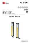
1
安全上のご注意 ●安全に使用していただくための表示と意味について この取扱説明書では、F3SJを安全にご使用いただくために、注意事項を次のよ うな表示と記号で示しています。 ここで示した注意事項は安全に関する重大な 内容を記載していますので、必ず守ってください。表示と記号は次のとおりです。 形 F3SJ-A□□□□N□□ (Version 2) セーフティライトカーテン 正しい取扱いをしなければ、発生しうる危険のため に、軽傷・中程度の障害を負ったり、 万一の場合に は重症や死亡に至る恐れがあります。 また同様に 重大な物的損害を受ける恐れがあります。 警告 ●警告表示 使用者について 取扱説明書 警 告 オムロン製品をお買い上げいただきありがとうございます。この製品を安 全に正しく使用していただくため、お使いになる前にこの説明書をお読み になり、十分にご理解ください。また、製品付属のCD-ROMにありますユ ーザーズマニュアルもお読みになり、十分にご理解ください。この説明書 とユーザーズマニュアルは、お読みになった後も、いつもお手元に置いて ご利用ください。 F3SJの設置や設定、及び機械制御システムへの組み込みは必ず適切な 訓練を受けた有資格者が実施してください。資格のない作業者が実施する と正しく動作しなくなり、人体が検出されず、重傷を負うおそれがあります。 設定ツール (形F39-GWUM、形F39-MC21) による各種機能の変更を 実施する場合は、管理者が変更内容の管理及び設定変更を実施してくだ さい。意図しない機能設定変更により人体が検出されず、重傷を負うおそ れがあります。 取付ける機械について 警 告 電気的制御による急停止が不可能な機械には適用できません。 たとえば、 フル回転クラッチを用いた機械プレスには使用しないでください。機械の危 険部に到達する前に機械が止まらず、重傷を負う恐れがあります。 補助出力や外部表示灯出力を安全用途に使用しないでください。F3SJ が故障しても人体が検出されず、重傷を負うおそれがあります。 取付けについて 警 告 * 7 9 2 8 7 9 5 - 9 G * © OMRON Corporation 2005 All Rights Reserved. (1/2) 法規・規格について 1. F3SJ単体では、労働安全衛生法第四十四条の二による 「型式検定」には 申請できず、 システムでの申請が必要となります。 したがって、F3SJを日本国 内で同法第四十二条で定められた 「プレス機械またはシャーの安全装置」 と して使用する場合には、 システムで検定を受けていただく必要があります。 2. F3SJは、EU(欧州連合)機械指令附属書IV B.安全部品 第1項で指 定される電気感知式保護装置(ESPE:Electro-Sensitive Protective Equipment)です。 3. EC適合宣言 オムロンは、F3SJが以下のEC指令の要求に適合していることを宣言します。 機械指令 Directive 2006/42/EC EMC指令 Directive 2004/108/EC 4. F3SJは、以下の規格に適合しています。 (1) 欧州規格 EN61496-1(タイプ4 ESPE) 、prEN61496-2(タイプ4 AOPD) 、 EN61508-1∼-7 (SIL3) (2) 国際規格 IEC61496-1(タイプ4 ESPE)、IEC61496-2(タイプ4 AOPD)、 IEC61508-1∼-7 (SIL3) (3) JIS規格 JIS B 9704-1(タイプ4 ESPE) 、JIS B 9704-2(タイプ4 AOPD) (4) 北米規格 UL61496-1(タイプ4ESPE)、UL61496-2(タイプ4AOPD)、 UL508、UL1998、CAN/CSA 22.2 No.14、CAN/CSA 22.2 No.0.8 5. F3SJは、EU公認機関TÜV SÜD Product Service GmbHから以下の 認証を取得しています。 ・機械指令に基づくEC型式試験 タイプ4ESPE(EN61496-1) 、 タイプ 4AOPD(prEN61496-2) ・TÜV SÜD Product Service型式認可 タイプ4 ESPE (EN61496-1) 、 タイプ4 AOPD (prEN61496-2) 、SIL1, 2, 3 (EN61508-1∼-7) 用途:EN954-1 カテゴリーB,1,2,3,4 6. F3SJは、第三者評価機関ULより米国およびカナダ安全規格に対するリス ティング認証を取得しています。 ・タイプ4 ESPE(UL61496-1) 、 タイプ4 AOPD(UL61496-2) 7. F3SJは以下の規格を考慮した設計になっております。 なお、最終システムを 下記の規格、規制に適合させるためには、関連するすべての規格、法規、規 制にしたがって設計、使用してください。不明な点は、ULなどの専門機関に ご相談ください。 ・欧州規格 EN415-4、EN692、EN693 ・米国労働安全衛生規則 OSHA 29 CFR 1910.212 ・米国労働安全衛生規則 OSHA 29 CFR 1910.217 ・米国規格 ANSI B11.1∼B11.19 ・米国規格 ANSI/RIA 15.06 ・カナダ規格協会 CSA Z142、Z432、Z434 ・SEMI スタンダード SEMI S2 ・厚生労働省「機械の包括的な安全基準に関する指針」 平成13年6月 1日基発第501号 ご注文・ご使用に際してのご承諾事項 当社制御機器商品をご注文いただく際、見積書、契約書、仕様書などに特記 事項のない場合には、次の保証内容、責任の制限、適合用途の条件などを適 用いたします。 下記内容をご確認いただき、 ご承諾のうえご注文およびご使用ください。 1. 保証内容 (1)保証期間 本製品の保証期間は、 ご購入後またはご指定の場所に納入後1年といた します。 (2)保証範囲 上記保証期間中に当社側の責により本製品に故障を生じた場合は、代 替品の提供または故障品の修理対応を、製品の購入場所において無償 で実施いたします。 ただし、故障の原因が次に該当する場合は、 この保証の対象範囲から除 外いたします。 a) カタログまたは取扱説明書などに記載されている以外の条件・環境・取 扱いならびにご使用による場合 b) 本製品以外の原因の場合 c) 当社以外による改造または修理による場合 d) 本製品本来の使い方以外の使用による場合 e) 当社出荷当時の科学・技術の水準では予見できなかった場合 f) その他、 天災、災害など当社側の責ではない原因による場合 なお、 ここでの保証は、本製品単体の保証を意味するもので、本製品の 故障により誘発される損害は保証の対象から除かれるものとします。 2. 責任の制限 (1)本製品に起因して生じた特別損害、間接損害、 または消極損害に関して は、 当社はいかなる場合も責任を負いません。 (2)プログラミング可能な製品については当社以外の者が行ったプログラム、 またはそれにより生じた結果について当社は責任を負いません。 3. 適合用途の条件 (1)本製品を他の商品と組み合わせて使用される場合、 お客様が適合すべ き規格・法規または規制をご確認ください。 また、 お客様が使用されるシステ ム、機械、装置への本製品の適合性は、 お客様自身でご確認ください。 こ れらを実施されない場合は、 当社は本製品の適合性について責任を負い ません。 (2)下記用途に使用される場合、 当社営業担当者までご相談のうえ仕様書な どによりご確認いただくとともに、定格・性能に対し余裕を持った使い方や、 万一故障があっても危険を最小にする安全回路などの安全対策を講じて ください。 a) 屋外の用途、潜在的な化学的汚染あるいは電気的妨害を被る用途ま たはカタログ・取扱説明書などに記載のない条件や環境での使用 b) 原子力制御設備、焼却設備、鉄道・航空・車両設備、医用機械、娯楽 機械、 および行政機関や個別業界の規制に従う設備 c) 人命や財産に危険が及びうるシステム・機械・装置 d) ガス、水道、電気の供給システムや24時間連続運転システムなど高い信 頼性が必要な設備 e) その他、 上記a)∼ d)に準ずる、高度な安全性が必要とされる用途 (3)お客様が本製品を人命や財産に重大な危険を及ぼすような用途に使用 される場合には、 システム全体として危険を知らせたり、冗長設計により必 要な安全性を確保できるよう設計されていること、 および本製品が全体の 中で意図した用途に対して適切に配電・設置されていることを必ず事前に 確認してください。 (4)カタログなどに記載されているアプリケーション事例は参考用ですので、 ご 採用に際しては機器・装置の機能や安全性をご確認のうえ、 ご使用くださ い。 (5)本製品が正しく使用されずお客様または第三者に不測の損害が生じるこ とがないよう使用上の禁止事項および注意事項をすべてご理解のうえ守 ってください。 4. 仕様の変更 カタログ・取扱説明書などに記載の商品の仕様および付属品は改善または その他の事由により、必要に応じて、変更する場合があります。当社営業担 当者までご相談のうえ本製品の実際の仕様をご確認ください。 5. サービスの範囲 本製品の価格には、技術者派遣などのサービス費用は含まれておりません。 お客様のご要望がございましたら、 当社営業担当者までご相談ください。 6. 価格 カタログに記載の標準価格はあくまで参考であり、確定されたユーザ購入価 格を表示したものではありません。 また消費税は含まれておりません。 7. 適用範囲 以上の内容は、 日本国内での取引および使用を前提としております。 日本国 外での取引および使用に関しては、 当社営業担当者までご相談ください。 F3SJを設置後、機械が動作しない状態でF3SJが意図したとおりに動作 することを必ず確認してください。意図したとおりに設定されていない場合、 人体が検出されず、重傷を負うおそれがあります。 使用上のご注意 製品が動作不能、誤動作、 または性能・機器への悪影響を防ぐため、以下のこ とを守ってください。 ■設置環境について 次のような場所には設置しないでください。 ・直射日光など、強い外乱光があたる場所 ・湿度が高く、結露する恐れがある場所 ・腐食性ガスがある場所 ・仕様で定められる以上の振動や衝撃が本体に伝わる場所 ・水がかかる場所 ・接着剤を溶かすような油のかかる場所 F3SJの間近で携帯電話やトランシーバを使用しないでください。 本製品はクラスA機器です。家庭用環境において、本製品は電波障害を起こ すことがあります。 この場合は、責任者が十分な対策を講じてください。 ■配線・取りつけについて ・配線は、必ず電源OFFの状態で行ってください。故障診断機能により、 F3SJが動作しなくなることがあります。 ・出力線を0Vラインに短絡させたままにしないでください。F3SJが故障する原因 となります。 定格 ■定格/性能表 形式中の□□□□には、検出幅 (mm) が4桁の数字で入ります。 形F3SJ-A□□□□N14 形F3SJ-A□□□□N20 形F3SJ-A□□□□N25 形F3SJ-A□□□□N30 形F3SJ-A□□□□N55 不透明体 不透明体 不透明体 最小検出物体 不透明体 不透明体 直径 25mm 直径 20mm 直径 14mm 直径 30mm 直径 55mm 25mm 20 mm 光軸ピッチ 9 mm 15 mm 50mm 13 ∼ 125 26 ∼ 234 16 ∼ 166 光軸数 10 ∼ 100 6 ∼ 50 検出幅 260 ∼ 2500 mm 245 ∼ 2495 mm 245 ∼ 2117 mm 245∼ 2495 mm 270∼ 2470 mm φ5mm レンズ径 0.2 ∼ 9m (検出幅1649mm以下)、0.2∼7m (検出幅1655mm以上)(設定ツールにより、検出距離を0.5mまで短縮可) 検出距離 ON→OFF : 10ms∼27.5ms以下、OFF→ON : 40ms∼110ms以下(安定入光時)詳細は裏面参照 応答時間 電源投入後立上がり時間 電源電圧(Vs) 消費電流(無負荷時) 投光器 F3SJ と危険部の間には、必ず安全距離を確保してください。機械の危険 部に到達する前に機械が止まらず、重傷を負う恐れがあります。 人体が検出エリアを通過してのみ機械の危険部に到達できるように機械 周辺に防護構造物を設置してください。機械の危険部で作業を行うとき、 常に人体の一部が検出エリア内に残るように設置してください。機械の危 険部とF3SJの検出エリアの間に人体が入り込んでしまう場合は、 インターロ ックがかかるシステムとし、機械の再始動を防止してください。人体が検出さ れず、重傷を負う恐れがあります。 インターロックリセットスイッチは、危険エリア全体が見え、 かつ危険エリア内か ら操作できない位置に設置してください。 F3SJは、危険エリアからの飛来物に対して人体を防護することはできませ ん。別途覆いまたは囲いを設けてください。 フィックスブランキング機能で無効化したエリアを通って機械の危険部に到 達できないように、無効化したエリア全体に防護構造物を設置してください。 人体が検出されず、重傷を負うおそれがあります。 受光器 光源(発光波長) 有効開口角(EAA) 制御出力(OSSD) ミューティング機能およびオーバーライ ド機能は装置の安全機能を無効にし ます。前記の機能が働いているときの安全性については、別の手段にて 確保してください。 補助出力1 (ノンセーフティ出力) NPN トランジスタ出力× 1、負荷電流300mA以下、残留電圧2V以下(コード延長による影響を除く)、 漏れ電流1mA以下 外部表示灯用出力 (ノンセーフティ出力) 接続可能な外部表示灯 ・白熱ランプ: DC24V、3∼7W ・LEDランプ:負荷電流 10∼300mA 漏れ電流1mA以下 (外部表示灯出力を使用するには、汎用表示灯コード形F39-JJ3N、または形F39-A01P□-PACが必要) 出力動作モード 制御出力 : 入光時ON 補助出力1 : 制御出力の反転出力(設定ツールで動作モードの変更可能) 補助出力2 : 通電時間が30000時間経過時にON (設定ツールで動作モードの変更可能) 外部表示灯出力1 : ベーシックシステム時 制御出力の反転出力、 ミューティングシステム時 ミューティング/オーバーライド時 ON(設定ツールで動作モードの変更可能) 外部表示灯出力2 : ベーシックシステム時 ロックアウト時ON、 ミューティングシステム時 ミューティング/オーバーライド時 ON(設定ツールで動作モードの変更可能) 入力電圧 テスト入力、インターロック選択入力、リセット入力、ミューティング入力ともに ON電圧 : 0∼1.5V (短絡電流3mA以下) OFF電圧: 9∼24V(Vs)、またはオープン 外部リレーモニタ入力 ON電圧 : 0∼1.5V (短絡電流5mA以下) OFF電圧: 9∼24V(Vs)、またはオープン 内部表示灯 ミューティング入力には、 独立した2つの入力機器を使用してください。 投光器 受光レベル表示灯(緑色LED×2、橙色LED×3) : 受光量に応じて点灯 エラーモード表示灯(赤色LED×3) : 異常内容を点滅表示 電源表示灯(緑色LED×1) : 通電時点灯 インターロック表示灯(黄色LED×1) : インターロック時に点灯、ロックアウト時に点滅 外部リレーモニタ表示灯[ミューティング入力1表示灯]、 ブランキング/テスト表示灯[ミューティング入力2表示灯] (緑色LED×2) : 機能に応じて点灯・点滅 受光器 受光レベル表示灯(緑色LED×2、橙色LED×3) : 受光量に応じて点灯 エラーモード表示灯(赤色LED×3) : 異常内容を点滅表示 OFF出力表示灯(赤色LED×1) : 制御出力OFF時に点灯、ロックアウト時に点滅 ON出力表示灯(緑色LED×1) : 制御出力ON時に点灯 ミューティングエラー表示灯、ブランキング/テスト表示灯(緑色LED×2) : 機能に応じて点灯・点滅 ミューティング中に作業者が危険エリアへ侵入できないように、 F3SJ ・ ミュー ティングセンサ・防護壁の配置、 および、 ミューティング関連時間設定をおこ なってください。 オーバーライ ドを起動するスイッチは、危険エリア全体が見え、 かつ危険エリ ア内から操作できない位置に設置してください。 また、 オーバーライ ドは必ず 危険エリアに誰もいないことを確認してから起動してください。 ∼50光軸まで: 68 mA以下、51∼100光軸: 90 mA以下、101∼150光軸: 111 mA以下、 151∼200光軸: 128 mA以下、201∼234光軸: 142 mA以下 赤外LED (波長870nm) IEC61496-2に基づく。投光器、受光器とも検出距離3m以上の時±2.5°以内 補助出力2( ノンセーフティ出力、 NPN トランジスタ出力× 1 、負荷電流50mA以下、残留電圧2V以下( コード延長による影響を除く)、 漏れ電流1mA以下 ベーシックシステム時の機能) ミューティングセンサは通過させる物体と人体の区別ができるように配置して ください。人体に反応してミューティング機能がはたらいた場合、重傷を負う おそれがあります。 ミューティング機能およびオーバーライ ド機能の状態を表示するミューティング ランプ (外部表示灯) はすべての操作位置から確認できる場所に配置して ください。 ミューティング機能に関連する時間は、適切な訓練を受けた有資格者が、 アプリケーションに合わせて的確な設定をしてください。特にミューティング時 間制限値を無限大に設定する際には、設定者自身が責任を持って実行 してください。 2s以下(直列連結時2.2s以下) DC24 V±20% (リップルp-p10%以下) ∼50光軸まで: 76 mA以下、51∼100光軸: 106 mA以下、101∼150光軸: 130 mA以下、 151∼200光軸: 153 mA以下、201∼234光軸: 165 mA以下 NPN トランジスタ出力× 2、負荷電流300 mA以下、残留電圧2 V以下(コード延長による影響を除く。 インダクタンス負荷を含む。)許容容量負荷2.2μF、漏れ電流2mA以下 (安全回路を採用しているので、従来使用されている論理(ON/OFF)と異なる場合あり) フィックスブランキングを設定した後、 すべての検出されるべきエリア内でテス トロッドが検出されることを必ず確認してください。人体が検出されず、重傷 を負うおそれがあります。 フィックスブランキング機能およびフローティングブランキング機能使用時は、 最小検出物体直径が大きくなります。安全距離の計算には、必ずフィックス ブランキング機能およびフローティングブランキング機能使用時の最小検出 物体直径を使用してください。機械の危険部に到達する前に機械が止ま らず、重傷を負うおそれがあります。 ・通信線を専用コード (形F39-JC□□)以外で延長する場合は、同等以上の 性能のコード (ツイストペア線) を使用してください。 シールドは0Vラインへ接続して ください。 ・コードのコネクタを、他のコネクタに取替える場合、 コネクタ内部の導体がIP54 以上で保護される構造としてください。 ・すべての端子の信号名を確認し、正しく配線してください。 ・制御システムは、F3SJの電源投入後2秒以上 (直列連結時2.2秒以上) 経過 してから作動させてください。 ・高圧線や動力線と同一配線管で使用しないでください。 ・市販のスイッチングレギュレータを使用する場合、FG(フレームグランド端子) を接地してください。 ・投光器と受光器の上下の方向を合わせて設置してください。 ・検出幅が600mm以上の場合、外形寸法図にしたがい、規定の数量、 および 位置にて中間取りつけ金具をご使用ください。 ご使用されない場合、定格/性能を満たすことができません。 ■清掃について シンナー、 ベンジン、 アセトン類は、樹脂部材やケース塗装を溶かしますので、使 用しないでください。 ■検出体について 透明体、半透明体は検出できません。 相互干渉防止機能 直列連結 干渉光回避アルゴリズム、検出距離変更機能 直列連結による時分割投光方式 ・連結数 : 4セットまで ・総光軸数: 400光軸まで ・2セット間の最大コード長さ: 15m以内 複数セットのF3SJを使用するときは、連結したり、 しゃ光板を使用するなど して、相互干渉が発生しないように設置してください。 テスト機能 ・セルフテスト(電源投入時および通電時) ・外部テスト(テスト入力による投光停止機能) 本体の取りつけ、 コードコネクタは確実に締めてください。 安全関連機能 ・スタートインターロック、リスタートインターロック( ミューティング機能使用時は、設定ツールで設定が必要) ・外部リレーモニタ ・ミューティング(ランプ断線検知、オーバーライド機能内蔵。ミューティング用キーキャップ形F39-CN6が必要) ・フィックスブランキング(設定ツールで設定が必要) ・フローティングブランキング(設定ツールで設定が必要) F3SJの設置は光沢面からの影響を受けないように設置してください。検 出不能状態となり、重傷を負う恐れがあります。 キャップを外しているときの、F3SJ内部、 またはコネクタ部に水・油・ほこりな どの異物が入らないようにしてください。 ミラーを使用して回帰反射型の配置では使用しないでください。検出不能 状態になることがあります。 ミラーで検出エリアを90° 曲げることは問題ありま せん。 全てのF3SJに対してユーザーズマニュアル「第6章 チェックリスト」に記 載の点検を実施してください。直列連結で使用する場合は連結されている 全てのF3SJに対して実施してください 配線について 警 告 負荷は出力と+24Vラインの間に接続してください (NPN出力)。誤って出 力と0Vラインの間に接続すると、動作モードが「しゃ光時ON」に反転して危 険です。 出力線を0Vラインに短絡させないでください。出力が常時ONとなり危険で す。 また、出力線の地絡によって出力がONとならないよう、電源の+24V側 を接地してください。 必要な安全カテゴリの要求事項を満たすように適切な数の制御出力を使 用してシステムを構成してください。 F3SJの各ラインをDC24V+20%を越えるDC電源に接続しないでください。 また、 AC電源にも接続しないでください。感電の可能性があり危険です。 F3SJがIEC 61496-1およびUL 508を満たすために、DC電源ユニットは 下記の項目すべてを満たすようにしてください。 ・定格の電源電圧内 (DC24V±20%)である ・複数の装置に接続する場合には、各装置の総定格電流に対して余裕を 持たせる。 ・EMC指令適合 (工業環境) ・一次回路、二次回路間が二重絶縁あるいは強化絶縁 ・過電流保護特性が自動復帰 (逆L垂下形) ・出力保持時間が20 ms以上 ・UL508で定義されるクラス2回路または制限電圧電流回路の出力特性 要求を満たす。 ・F3SJ が使用される国、地域でのEMC と電気機器安全に関する法規・ 規格に従う電源である。 (例: EU ではEMC指令、低電圧指令に適合の 電源であること) すべての入出力線は、危険電圧から二重絶縁あるいは強化絶縁により絶 縁されているようにしてください。感電の可能性があり危険です。 コード延長は規定以内の長さとしてください。安全機能が正常に働かない 可能性があり危険です。 その他 接続方式 保護回路 周囲温度 周囲湿度 使用周囲照度 絶縁抵抗 耐電圧 保護構造 耐振動 耐衝撃 電源コード、直列連結コード (形F39-JJR□L、JJR3W) 延長コード (形F39-JC□A、JC□B) 材質 質量(梱包状態) F3SJの日常点検、6 ヶ月ごとの点検を必ず実施してください。 システムが正 常に動作せず、重傷を負うおそれがあります。 安全上の要点 以下に示すような項目は安全を確保する上で必要なことですので必ず守って ください。 ・本書をよく読んで、設置手順、動作確認手順、及びメンテナンス手順を十分に ご理解の上、 ご使用ください。 ・負荷は、下記の項目すべてを満たすようにしてください。 -短絡させない -定格以上の電流を流さない ・製品を落下させないでください。 ・使用している国の該当する廃棄物処理規則に従って廃棄して下さい。 φ6.6mm8芯(0.3mm2×4対、導体抵抗0.058Ω/m)編組シールド付き 許容曲げ半径R36mm (コードを延長する場合、同等以上の性能のコード(ツイストペア線)を使用し、高圧線や動力線と同一配管で 使用しないでください)延長可能な長さについて(電源コード長さ)裏面を参照 ケース(両端の金属部も含む):アルミ、亜鉛ダイキャスト キャップ: ABS樹脂 光学カバー: PMMA樹脂(アクリル) コード:耐油性PVC ・形F3SJ-A□□□□N14 質量(g) = (検出幅) ×1.7+α ・形F3SJ-A□□□□N20/形F3SJ-A□□□□N25/形F3SJ-A□□□□N30 質量(g) = (検出幅) ×1.5+α ・形F3SJ-A□□□□N55 質量(g) = (検出幅) ×1.4+α αは以下の値となります。 検出幅245∼596mmのとき 1100 検出幅600∼1130mmのとき 1500 検出幅1136∼1658mmのとき 2000 検出幅1660∼2180mmのとき 2400 検出幅2195∼2500mmのとき 2600 付属品 テストロッド(※1)、取扱説明書、ユーザーズマニュアル(CD-ROM)、上下取りつけ金具、 中間取りつけ金具(※2)、エラーモードラベル ※1 形F3SJ-A□□□□N55ߦߪઃዻߒ߹ߖࠎ ※2 中間取りつけ金具の数は、検出幅によって変わります 検出幅600∼1130mmのとき投・受光器に各1セット付属 検出幅1136∼1658mmのとき投・受光器に各2セット付属 検出幅1660∼2180mmのとき投・受光器に各3セット付属 検出幅2195∼2500mmのとき投・受光器に各4セット付属 適合規格 IEC61496-1、EN61496-1、UL61496-1タイプ4ESPE (Electro-Sensitive Protective Equipment) IEC61496-2、prEN61496-2、UL61496-2タイプ4AOPD (Active Opto-electronic Protective Devices) IEC61508、EN61508 SIL3 警 告 F3SJをPSDIモード (センサによるサイクル運転の再始動) でご使用になる には、F3SJ と機械の間に適切な制御回路を構成する必要があります。 PSDIについての詳細は、OSHA1910.217、IEC61496-1、 およびその他 の関連する規格、規制を参照ください。 本体を分解、修理、改造しないでください。本来の安全機能が失われ危険 です。 F3SJを引火性、爆発性ガスの雰囲気中で使用しないでください。爆発の 恐れがあります。 コネクタ式(M12、8ピン) 出力負荷短絡保護、電源逆接続保護 動作時:−10∼55℃(ただし氷結しないこと)、保存時:−30∼70℃ 動作時: 35∼85%RH (ただし結露しないこと)、保存時: 35∼95%RH 白熱ランプ:受光面照度3,000 lx以下、太陽光:受光面照度10,000 lx以下 20MΩ以上(DC500 V メガにて) AC1,000V、50/60Hz、1min IP65 (IEC60529) 誤動作 : 10∼55Hz、複振幅0.7mm、 X、Y、Z各方向 20掃引 誤動作 : 100m/s2、 X、Y、Z各方向 1000回 φ6mm8芯(0.15mm2×8)編組シールド付き 許容曲げ半径R5mm オムロン株式会社 営業統轄事業部 東京都品川区大崎1-11-1 ゲートシティ大崎ウエストタワー14F(〒141-0032) ●技術的なお問い合わせ 0120−919−066 (フリーコール) 携帯電話・PHSなどは 055-982-5015です。 直通のセンシング機器の技術窓口は055-982-5002です。 ■営業時間:9:00∼12:00/13:00∼19:00 (土・日・祝祭日は17:00まで) ■営業日:年末年始を除く ●FAXによるお問い合わせ テクニカルセンタ お客様相談室 FAX:055-982-5051 ●インターネットによるお問い合わせ http://www.fa.omron.co.jp/support/ ●FAQ (よくあるご質問) ホームページをご用意しています。 http://www.dom.omron.co.jp/faq.nsf/ 配線図 内部表示灯 [ベーシックシステム] ■マニュアルリセットモード、外部リレーモニタ機能を使用する場合の配線図 ■内部表示灯 投光器 投光器 受光器 S1: 外部テストスイッチ (スイッチが不要な場合、24Vに接続) S2: インターロック/ロックアウトリセットスイッチ K1、K2: 機械の危険部を制御するリレー等 K3、K4: 負荷、PLC等(モニター用) LEVEL 1. 受光レベル表示灯 *1 微小負荷用スイッチ(入力仕様:5V、1mA)を ご使用ください。 *2 K3、K4が未接続でもF3SJは動作します。 (灰) 通信線(+) LEVEL 5 5 4 4 LEVEL-3(橙) 3 3 LEVEL-2(橙) LEVEL-1(橙) 2 2 LEVEL-2(橙) 1 1 LEVEL-1(橙) C C B B ERROR-C(赤) ERROR-B(赤) A ERROR-B(赤) A *1 K3 K2 K1 シールド線 0V (青) 制御出力2 (白) 制御出力1 (緑) 補助出力1 (黄) 24V (茶) 24V (茶) リセット入力 (黄) S2 POWER INTLK OFF MUTE 1 MUTING ERROR MUTE 2 BLANKING (TEST) ON EDM BLANKING (TEST) K2 *2 RECEIVER *1 3. 電源表示灯(緑) 4. インターロック表示灯(黄) 5. 外部リレーモニタ表示灯(緑) [ミューティング入力1表示灯] 6. ブランキング/テスト表示灯(緑) [ミューティング入力2表示灯] 1. 受光レベル表示灯 2. エラーモード表示灯 ERROR EMITTER *2 S1 外部リレーモニタ入力 (赤) K4 テスト入力 (緑) インターロック選択入力(白) 補助出力2(赤) 0V (青) シールド線 ERROR K1 LEVEL-5(緑) LEVEL-4(緑) LEVEL-3(橙) LEVEL-5(緑) LEVEL-4(緑) ERROR-C(赤) ERROR-B(赤) ERROR-A(赤) 2. エラーモード表示灯 (桃) 通信線(-) 受光器 *1 φ30 7. OFF出力表示灯(赤) 8. ON出力表示灯(緑) 9. 未使用(緑) [ミューティングエラー表示灯] 10. 未使用(緑) [ブランキング/テスト表示灯] φ30 +24V DC [ ]内はミューティングシステム時の表示灯名称です。 電源 0V ■オートリセットモードの配線図 *1 ミューティング用キーキャップ形F39-CN6に添付されています。 キーキャップ装着時にこのシールを貼付してください。 ■外部リレーモニタ機能を使用しない場合の配線図 ■ベーシックシステム時の内部表示灯の点灯パターン 1.設定ツールを使用して外部リレーモニタ機能を 「無効」に設定する または、 2.設定変更していない補助出力1 (出力モードが「制御出力情報」、反転モード が「有効」) のとき補助出力1と外部リレーモ ニタ入力を 下図のように接続することで外部 リレーモニタ機能が 無効となります。 受光器 投光器 投光器側の配線を下図の様に配線 することで、オートリセットモー ドとなります。 No. 1 2 内部表示灯 受光レベル表示灯 エラーモード表示灯 LEVEL-1∼5 ERROR-A∼C 3 電源表示灯 POWER 4 インターロック表示灯 INTLK 5 外部リレーモニタ表示灯 EDM 6 ブランキング/テスト表示灯 BLANKING /TEST 7 OFF出力表示灯 OFF 8 ON出力表示灯 ON 点灯/点滅 点灯 点灯/点滅 説明 1∼5の点灯状態で、F3SJの受光状態を示します。 F3SJがロックアウトした場合に点灯/点滅し、A∼Cの状態によりエラ ー原因を示します。F3SJが直列連結されている場合はそれぞれのエラ ー内容に応じて点灯/点滅します。付属のエラーモードラベルをF3SJ の近くに貼付けて使用すると、エラー発生時に原因を調べやすくなり ます。エラーモードの詳細については「■エラーモード表示灯の点灯 パターン」を参照して下さい。 点灯 点滅 点灯 点滅 点灯 電源が投入されているときに点灯します。 保守状態のときに点滅します。 F3SJがインターロック状態の場合に点灯します。 ロックアウト時に点滅します。 外部リレーモニタ入力に入力があると点灯します。 ブランキング機能、警告エリア機能を有効に設定した場合に点灯します。 外部テスト中に点滅します。 制御出力がOFFのときに点灯します。 以下の場合に点滅します; ・ロックアウト状態。 ・保守状態で1光軸以上しゃ光された状態。 (灰) 通信線(+) S1 *1 *2 S3 *1 K3 K1 シールド線 0V (青) 制御出力2 (白) 制御出力1 (緑) 補助出力1 (黄) 24V (茶) 24V (茶) リセット入力 (黄) 外部リレーモニタ入力 (赤) K4 テスト入力 (緑) インターロック選択入力(白) 補助出力2(赤) 0V (青) シールド線 (桃) 通信線(-) K2 *3 +24V DC 点灯 +24V DC 0V 0V *3 K3が未接続でもF3SJは動作します。 K3が不要な場合、補助出力1は外部リレーモニタ入力と接続する のみと してください。 *1 微小負荷用スイッチ(入力仕様:5V、1 mA)をご使用ください。 *2 K4が未接続でもF3SJは動作します。 [ミューティングシステム] ■外部リレーモニタ機能を使用する場合の配線図 M1 *4 *4 制御出力がONのときに点灯します。 点滅 保守状態で光軸がしゃ光されていない時に点滅します。 9 − − − − 10 − − − − ■ミューティングシステム時の内部表示灯の点灯パターン (ベーシックシステム時と異なる表示灯のみ記載) K1、K2: 機械の危険部を制御するリレー等 K3: 負荷、PLC等(モニター用) S1: 外部テストスイッチ(スイッチが不要な場合、24Vに接続) S3: ロックアウトリセットスイッチ(スイッチが不要な場合、0Vに接続) K4: 負荷、PLC等(モニター用) 点灯 点滅 点灯 点滅 受光器 投光器 S1: 外部テストスイッチ (スイッチが不要な場合、24Vに接続) S2: ロックアウトリセットスイッチ (スイッチが不要な場合、0Vに接続) A1: ミューティングセンサA1による接点 B1: ミューティングセンサB1による接点 K1、K2: 機械の危険部を制御するリレー等 K3: 負荷、PLC等(モニター用) M1: ミューティングランプ No. 5 内部表示灯 ミューティング入力1表示灯 MUTE1 6 ミューティング入力2表示灯 MUTE2 9 ミューティングエラー表示灯 MUTING ERROR 10 ブランキング/テスト表示灯 BLANKING /TEST 点灯/点滅 点灯 点滅 点灯 点滅 点灯 説明 ミューティング入力1に入力があると点灯します。 ミューティング・オーバーライド中に点滅します。 ミューティング入力2に入力があると点灯します。 ミューティング・オーバーライド中に点滅します。 ミューティングエラー中に点灯します。 点灯 点滅 ブランキング機能を有効に設定した場合に点灯します。 外部テスト中に点滅します。 ■受光レベル表示灯の点灯パターン 1 2 3 4 5 受光レベル 制御出力ONレベルの170%以上 制御出力ONレベルの130∼170%未満 制御出力ONレベルの100∼130%未満 制御出力ONレベルの75∼100%未満 制御出力ONレベルの50∼75%未満 制御出力ONレベルの50%未満 点灯 消灯 A1 *5 S1 *1 K1 K3 K2 K1 シールド線 0V (青) 制御出力2 (白) 制御出力1 (緑) 補助出力1 (黄) 24V (茶) 24V (茶) リセット入力 (黄) S2 *1 *2 外部リレーモニタ入力 (赤) B1 *5 テスト入力 (緑) ミューティング入力1(白) ミューティング入力2(赤) 0V (青) シールド線 受光レベル100%以上で動作しますが、安定して使用するには5個点灯した状態で使用してください。 K2 *3 *4 +24V DC 0V *1 微小負荷用スイッチ(入力仕様:5V、1mA)をご使用ください *2 インターロック機能使用時には、インターロックリセットスイッチとしても機能します(設定ツールでの設定が必要) *3 K3が未接続でもF3SJは動作します *4 外部表示灯出力1、外部表示灯出力2あるいは補助出力1のいずれかにミューティングランプを接続してください。 補助出力1にミューティングランプを接続する際には設定ツールでの設定変更が必要です。 *5 2線式のセンサは使用できません ■外部リレーモニタ機能を使用しない場合の配線図 ベーシックシステムの「外部リレーモニタ機能を使用しない場合の配線」 と同じです。 入出力回路図 ■入出力回路図 ○内の数字は、 コネクタのピンNo.を示します。●は、直列連結用のコネクタを示します。[ ]内はミューティングシステムのときの信号名を示します。 外部表示灯用 出力 2 茶 表示部 投光器 主回路 青 2 茶 3 緑 1 白 4 黄 8 7 灰 通信線(+) 5 灰 赤 +24VDC テスト入力*1 インターロック選択入力 [ミューティング入力1] リセット入力 補助出力2 [ミューティング入力2] *1開放または24Vに短絡:通常動作 0Vに短絡:投光停止 青 シールド 6 桃 通信線(-) 桃 5 6 2 外部表示灯用 出力 1 茶 1 茶 負荷 白 制御出力2 負荷 受光器 主回路2 青 3 受光器 主回路1 緑 制御出力1 補助出力1 8 赤 外部リレーモニタ入力 7 青 シールド 26∼29 245∼272 30∼42 281∼389 398∼506 43∼55 56∼67 515∼614 68∼80 623∼731 81∼112 740∼1019 1028∼1307 113∼144 1316∼1595 145∼176 177∼208 1604∼1883 209∼234 1892∼2117 F3SJ-A□□□□N25シリーズ 検出幅 [ mm ] 光軸数 260∼320 340∼580 600∼840 860∼1100 1120∼1340 1360∼1600 1620∼2240 2260∼2500 13∼16 17∼29 30∼42 43∼55 56∼67 68∼80 81∼112 113∼125 270∼770 820∼1420 1470∼2070 2120∼2470 黄 表示部 ■応答時間 F3SJ-A□□□□N14シリーズ 検出幅 光軸数 [ mm ] F3SJ-A□□□□N55シリーズ 検出幅 光軸数 [ mm ] 負荷 4 ■エラーモード表示灯の点灯パターン エラー主原因 A B C 相互干渉、外乱光の入光。 F3SJの電源電圧が定格から外れている。電源の電流容量不足など。 ブランキング光軸に入光した。 通信線の断線、配線ミス、直列連結コード外れ、ノイズの影響、その他異常。 投受光器でF3SJの形式、直列連結数が異なる。 設定ツールで設定した機能設定値が、有効範囲から外れている。 キャップ未装着。F3SJ内部回路の故障。 リレーの溶着、復帰時間が長い。外部リレーモニタ線の配線ミス、断線。 インターロック選択入力線、またはリセット入力線の配線ミス、断線。 ミューティングシステム時、リセット入力線の配線ミス、断線。 制御出力1もしくは制御出力2の配線ミス。制御出力回路の故障。 直列連結コードの配線ミス、断線。 外部表示灯出力の配線ミス、断線。 補助出力1の短絡、断線。 直列連結コードの断線。 通信線の配線ミス、断線。 ノイズの影響。F3SJ内部回路の故障。 詳しくはF3SJユーザーズマニュアルを参照してください。 6∼16 17∼29 30∼42 43∼50 点滅 消灯 応答時間/電源コード長さ 応答時間 (ON→OFF) [ ms ] 11 12 13 14 15 17.5 20 22.5 25 27.5 応答時間 (OFF→ON) [ ms ] 44 48 52 56 60 70 80 90 100 110 応答時間 (ON→OFF) [ ms ] 10 11 12 13 14 15 17.5 20 応答時間 (OFF→ON) [ ms ] 40 44 48 52 56 60 70 80 応答時間 (ON→OFF) [ ms ] 10 11 12 13 応答時間 (OFF→ON) [ ms ] 40 44 48 52 F3SJ-A□□□□N20シリーズ 検出幅 光軸数 [ mm ] 16 245 17∼29 260∼440 30∼42 455∼635 43∼55 650∼830 845∼1010 56∼67 68∼80 1025∼1205 81∼112 1220∼1685 113∼144 1700∼2165 2180∼2495 145∼166 F3SJ-A□□□□N30シリーズ 検出幅 光軸数 [ mm ] 245∼395 420∼720 745∼1045 1070∼1370 1395∼1670 1695∼1995 2020∼2495 ■電源コード長さ 電源コードの延長は、下記の表以下としてください。 0V 点灯 条件 単独 2連結 3連結 4連結 白熱表示灯を補助出力、外部表示灯出力に使用する 45m 40m 30m 20m 白熱表示灯を使用しない 100m 60m 45m 30m 10∼16 17∼29 30∼42 43∼55 56∼67 68∼80 81∼100 応答時間 (ON→OFF) [ ms ] 10 11 12 13 14 15 17.5 20 22.5 応答時間 (OFF→ON) [ ms ] 40 44 48 52 56 60 70 80 90 応答時間 (ON→OFF) [ ms ] 10 11 12 13 14 15 17.5 応答時間 (OFF→ON) [ ms ] 40 44 48 52 56 60 70 直列連結の場合は、次のように計算します。 ・2セットの直列の場合 -応答時間 (ON→OFF) :プライマリセンサの応答時間+セカンダリセンサ1の 応答時間−1 [ ms ] -応答時間 (OFF→ON) :応答時間 (ON→OFF) ×4 [ ms ] ・3セットの直列の場合 -応答時間 (ON→OFF) :プライマリセンサの応答時間+セカンダリセンサ1の 応答時間+セカンダリセンサ2の応答時間−5 [ ms ] -応答時間 (OFF→ON) :応答時間 (ON→OFF) ×5 [ ms ] ・4セットの直列の場合 -応答時間 (ON→OFF) :プライマリセンサの応答時間+セカンダリセンサ1の 応答時間+セカンダリセンサ2の応答時間 +セカンダリセンサ3の応答時間−8 [ ms ] -応答時間 (OFF→ON) :応答時間 (ON→OFF) ×5 [ ms ] PRECAUTIONS ON SAFETY PRECAUTIONS FOR CORRECT USE Regarding the alert symbols and meanings used for the safe uses In order for our customers to use the F3SJ in safety, precautions are indicated in this manual with the alert symbols and statements such as the followings. Those safety precautions relate to the important descriptions that must be obeyed for the safe uses and operations. Be sure to obey the precautions. The following indictions and symbols are used for the descriptions. The F3SJ must be installed, configured, and incorporated into a machine control system by a sufficiently trained and qualified person. An unqualified person may not be able to perform these operations properly, which may cause a person to go undetected, resulting in serious injury. Observe the precautions described below to prevent operation failure, malfunctions, or undesirable effects on product performance. ■Installation environment Do not install the F3SJ in the following types of environments: •Areas exposed to intense interference light, such as direct sunlight •Areas with high humidity where condensation is likely to occur •Areas where corrosive gases are present •Areas exposed to vibration or shock levels higher than in the specification provisions •Areas where the product may come into contact with water •Areas where the product may get wet with oil that can solve adhesive Do not use radio equipment such as cellular phones, walkie-talkies, or transceivers near the F3SJ. This is a class A product. In residential areas it may cause radio interference. in which case the Responsible Person may be required to take adequate measures to reduce interference. ■Wiring and installation •Make sure to perform wiring while the power supply is OFF. Otherwise, the F3SJ may fail to operate due to the diagnosis function. •Do not short-circuit output lines to 0V line. Otherwise a fault of F3SJ may occur. When changes are made to each function using the setting tool (F39-GWUM or F39-MC21), the administrator must manage the details of the changes and perform the changes. Accidental functional setting change may cause failure of human body detection, resulting in a serious injury. ■Ratings/Specifications In the type names in this table, the **** contain the 4 digits indicating the protective height (mm). Original instructions Model F3SJ-A□□□□N□□ (Version 2) SAFETY LIGHT CURTAIN WARNING Indicates a potentially hazardous situation which, if not avoided, will result in minor or moderate injury, or may result in serious injury or death. Additionally there may be significant property damage. Alert Statements in this Manual For Users WARNING INSTRUCTION SHEET Please read and understand this instruction sheet before storing, installing, programming, operating, maintaining, or disposing of the products. Please consult your OMRON representative if you have any questions or comments. Please refer to the User’s Manual for detailed instructions on usage. RATINGS For Machines (Representative in EU) Wegalaan 67-69. 2132 JD Hoofddorp The NETHERLANDS WARNING Do not use this sensor for machines that cannot be stopped by electrical control. For example, do not use it for a pressing machine that uses full-rotation clutch. Otherwise, the machine may not stop before a person reaches the hazardous part, resulting in serious injury. Do not use the auxiliary output or external indicator output for safety applications. Human body may not be detected when F3SJ fails, resulting in serious injury. Detection capability Beam gap Number of beams Protective height Lens diameter Operating range * 7 9 2 8 7 9 5 - 9 G * For Installation © OMRON Corporation 2005 All Rights Reserved. (2/2) LEGISLATION AND STANDARDS 1. Application of a F3SJ sensor alone cannot receive type approval provided by Article 44-2 of the Labour Safety and Health Law of Japan. It is necessary to apply it in a system. Therefore, when using the F3SJ in Japan as a "safety system for pressing or shearing machines" prescribed in Article 42 of that law, the system must receive type approval. 2. The F3SJ is electro-sensitive protective equipment (ESPE) in accordance with European Union (EU) Machinery Directive Index Annex IV, B, Safety Components, Item 1. 3. EC Declaration of Conformity OMRON declares that F3SJ is in conformity with the requirements of the following EC Directives: Machinery Directive 2006/42/ECޓ EMC Directive 2004/108/EC 4. F3SJ is in conformity with the following standards: (1) European standards EN61496-1 (Type 4 ESPE), prEN61496-2 (Type 4 AOPD), EN61508-1 through -7 (SIL3) (2) International standards IEC61496-1 (Type 4 ESPE), IEC61496-2 (Type 4 AOPD), IEC61508-1 through -7 (SIL3) (3) JIS standards JIS B 9704-1 (Type 4 ESPE), JIS B 9704-2 (Type 4 AOPD) (4) North American Standards: UL61496-1(Type 4ESPE), UL61496-2(Type 4AOPD), UL508, UL1998, CAN/CSA 22.2 No.14, CAN/CSA 22.2 No.0.8 5. The F3SJ received the following approvals from the EU accredited body, TÜV SÜD Product Service GmbH: •EC Type-Examination in accordance with the EU Machinery Directive, Type 4 ESPE (EN61496-1), Type 4 AOPD (prEN61496-2) •TÜV SÜD Product Service Type Approval, Type 4 ESPE (EN61496-1), Type 4 AOPD (prEN61496-2), SIL1, 2, 3 (EN61508-1 through -7), Application: EN954-1 Category B,1,2,3,4 6. The F3SJ received the certificates of UL listing for US and Canadian safety standards from the Third Party Assessment Body UL. •Both are: Type 4 ESPE (UL61496-1), Type 4 AOPD (UL61496-2) 7. The F3SJ is designed according to the standards listed below. To make sure that the final system complies with the following standards and regulations, you are asked to design and use it in accordance with all other related standards, laws, and regulations. If you have any questions, consult with specialized organizations such as the body responsible for prescribing and/or enforcing machinery safety regulations in the location where the equipment is to be used. •European Standards: EN415-4, EN692, EN693 •U.S. Occupational Safety and Health Standards: OSHA 29 CFR 1910.212 •U.S. Occupational Safety and Health Standards: OSHA 29 CFR 1910.217 •American National Standards: ANSI B11.1 to B11.19 •American National Standards: ANSI/RIA 15.06 •Canadian Standards Association CSA Z142, Z432, Z434 •SEMI Standards SEMI S2 •Ministry of Health, Labour and Welfare "Guidelines for Comprehensive Safety Standards of Machinery", Standard Bureau's Notification No. 501 dated June 1, 2001. READ AND UNDERSTAND THIS DOCUMENT Please read and understand this document before using the products. Please consult your OMRON representative if you have any questions or comments. WARRANTY OMRON’s exclusive warranty is that the products are free from defects in materials and workmanship for a period of one year (or other period if specified) from date of sale by OMRON. OMRON MAKES NO WARRANTY OR REPRESENTATION, EXPRESS OR IMPLIED, REGARDING NONINFRINGEMENT, MERCHANTABILITY, OR FITNESS FOR PARTICULAR PURPOSE OF THE PRODUCTS. ANY BUYER OR USER ACKNOWLEDGES THAT THE BUYER OR USER ALONE HAS DETERMINED THAT THE PRODUCTS WILL SUITABLY MEET THE REQUIREMENTS OF THEIR INTENDED USE. OMRON DISCLAIMS ALL OTHER WARRANTIES, EXPRESS OR IMPLIED. LIMITATIONS OF LIABILITY OMRON SHALL NOT BE RESPONSIBLE FOR SPECIAL, INDIRECT, OR CONSEQUENTIAL DAMAGES, LOSS OF PROFITS OR COMMERCIAL LOSS IN ANY WAY CONNECTED WITH THE PRODUCTS, WHETHER SUCH CLAIM IS BASED ON CONTRACT, WARRANTY, NEGLIGENCE, OR STRICT LIABILITY. In no event shall responsibility of OMRON for any act exceed the individual price of the product on which liability is asserted. IN NO EVENT SHALL OMRON BE RESPONSIBLE FOR WARRANTY, REPAIR, OR OTHER CLAIMS REGARDING THE PRODUCTS UNLESS OMRON’S ANALYSIS CONFIRMS THAT THE PRODUCTS WERE PROPERLY HANDLED, STORED, INSTALLED, AND MAINTAINED AND NOT SUBJECT TO CONTAMINATION, ABUSE, MISUSE, OR INAPPROPRIATE MODIFICATION OR REPAIR. SUITABILITY FOR USE OMRON shall not be responsible for conformity with any standards, codes, or regulations that apply to the combination of products in the customer’s application or use of the product. At the customer’s request, OMRON will provide applicable third party certification documents identifying ratings and limitations of use that apply to the products. This information by itself is not sufficient for a complete determination of the suitability of the products in combination with the end product, machine, system, or other application or use. The following are some examples of applications for which particular attention must be given. This is not intended to be an exhaustive list of all possible uses of the products, nor is it intended to imply that the uses listed may be suitable for the products: • Outdoor use, uses involving potential chemical contamination or electrical interference, or conditions or uses not described in this document. • Nuclear energy control systems, combustion systems, railroad systems, aviation systems, medical equipment, amusement machines, vehicles, and installations subject to separate industry or government regulations. • Systems, machines, and equipment that could present a risk to life or property. Please know and observe all prohibitions of use applicable to the products. NEVER USE THE PRODUCTS FOR AN APPLICATION INVOLVING SERIOUS RISK TO LIFE OR PROPERTY WITHOUT ENSURING THAT THE SYSTEM AS A WHOLE HAS BEEN DESIGNED TO ADDRESS THE RISKS, AND THAT THE OMRON PRODUCT IS PROPERLY RATED AND INSTALLED FOR THE INTENDED USE WITHIN THE OVERALL EQUIPMENT OR SYSTEM. PERFORMANCE DATA Performance data given in this document is provided as a guide for the user in determining suitability and does not constitute a warranty. It may represent the result of OMRON’s test conditions, and the users must correlate it to actual application requirements. Actual performance is subject to the OMRON Warranty and Limitations of Liability. CHANGE IN SPECIFICATIONS Product specifications and accessories may be changed at any time based on improvements and other reasons. It is our practice to change model numbers when published ratings or features are changed, or when significant construction changes are made. However, some specifications of the product may be changed without any notice. When in doubt, special model numbers may be assigned to fix or establish key specifications for your application on your request. Please consult with your OMRON representative at any time to confirm actual specifications of purchased products. DIMENSIONS AND WEIGHTS Dimensions and weights are nominal and are not to be used for manufacturing purposes, even when tolerances are shown. ERRORS AND OMISSIONS The information in this document has been carefully checked and is believed to be accurate; however, no responsibility is assumed for clerical, typographical, or proofreading errors, or omissions. PROGRAMMABLE PRODUCTS OMRON shall not be responsible for the user’s programming of a programmable product, or any consequence thereof. COPYRIGHT AND COPY PERMISSION This document shall not be copied for sales or promotions without permission. This document is protected by copyright and is intended solely for use in conjunction with the product. Please notify us before copying or reproducing this document in any manner, for any other purpose. If copying or transmitting this document to another, please copy or transmit it in its entirety. Response time WARNING Make sure to test the operation of the F3SJ after installation to verify that the F3SJ operates as intended. Make sure to stop the machine until the test is complete. Unintended function settings may cause a person to go undetected, resulting in serious injury. Make sure to install the F3SJ at the safe distance from the hazardous part of the equipment. Otherwise, the machine may not stop before a person reaches the hazardous part, resulting in serious injury. Install a protective structure so that the hazardous part of a machine can only be reached by passing through the sensor's detection zone. Install the sensors so that part of the person is always present in the detection zone when working in a machine's hazardous areas. If a person is able step into the hazardous area of a machine and remain behind the F3SJ's detection zone, configure the system with an interlock function that prevents the machine from being restarted. Failure to do so may result in serious injury. Install the interlock reset switch in a location that provides a clear view of the entire hazardous area and where it cannot be activated from within the hazardous area. The F3SJ cannot protect a person from an object flying from a hazardous area. Install protective cover(s) or fence(s). To prevent personnel approach to dangerous part of the machine through an area disabled by the fixed blanking function, you must install a protective structure to cover the whole disabled area. Failure to do so may cause failure of human body detection, resulting in a serious injury. You must ensure that a test rod is detected for all detection areas except where fixed blanking function is used. Failure to do so may cause failure of human body detection, resulting in a serious injury. Startup waiting time Power supply voltage(Vs) Current Emitter consumption (no load) Receiver Light source Effective aperture angle (EAA) Safety outputs(OSSD) Auxiliary output 1 (Non-safety output) Auxiliary output 2 (non-safety output, afunction for a basic system) External indicator output (Non-safety output) Output operation mode Detection capability gets larger when fixed/floating blanking function is used. You must use the detection capability for fixed and floating blanking functions. Failure to do so may cause failure of machine stop before reaching the machine's dangerous part, resulting in a serious injury. The muting and override functions disable the safety functions of the device. You must ensure safety using other method when these functions are operating. Input voltage Install muting sensors so that they can distinguish between the object that is being allowed to pass through the detection zone and a person. If the muting function is activated by the detection of a person, it may result in serious injury. Muting lamps (external indicators) that indicate the state of the muting and override functions must be installed where they are clearly visible to workers from all the operating positions. Muting related time must be properly configured for its application by a sufficiently trained and qualified person, and the person must have responsibility for settings, especially when setting the muting time limit to infinite. Use independent 2 input devices for muting inputs. You must install F3SJ, muting sensor, and physical barrier, and configure time settings for muting so that an operator should not enter hazardous zone. Install the switch that activates the override in a location that provides a clear view of the entire hazardous area and where it cannot be activated from within the hazardous area. Make sure that nobody is in the hazardous area before activating the override function. Install the sensor system so that it is not affected by the reflective surface of the F3SJ. When using more than 1 set of F3SJ, install them so that mutual interference does not occur, such as by configuring series connections or using physical barriers between adjacent sets. Make sure that the F3SJ is securely mounted and its cables and connectors are properly connected. Make sure that foreign material such as water, oil, or dust does not enter the F3SJ or the connector while the cap is removed. Do not use the sensor system with mirrors in a retro-reflective configuration. Doing so may hinder detection. It is possible to use mirrors to "bend" the detection zone to a 90-degree angle. Perform an inspection for all F3SJ as described in "Chapter 6 Checklists" of User’s manual. When using series connections,perform inspections for every connected F3SJ. For Wiring WARNING Connect the load between the output and 24V line (NPN output). Connecting the load between the output and 0V line will result in a dangerous condition because operation is reversed to "ON when blocked". Do not short-circuit the output line to the 0V line. Otherwise, the output is always ON. Also, the +24V of the power supply must be grounded so that output does not turn ON due to grounding of the output line. Configure the system by using the optimal number of safety outputs that satisfy the requirements of the necessary safety category. Do not connect each line of F3SJ to a DC power supply of more than 24VDC+20%. Also, do not connect to an AC power supply. Failure to do so may result in electric shock. For the F3SJ to comply with IEC 61496-1 and UL 508, the DC power supply unit must satisfy all of the following conditions: • Must be within the rated power voltage (24V DC ± 20%) • Must have tolerance against the total rated current of devices if it is connected to multiple devices • Must comply with EMC directives (industrial environment) • Double or reinforced insulation must be applied between the primary and secondary circuits • Automatic recovery of overcurrent protection characteristics (reversed L sagging) • Output holding time must be 20ms or longer • Must satisfy output characteristic requirements for class 2 circuit or limited voltage current circuit defined by UL508 • Must comply with laws and regulations, regarding EMC and electrical equipment safety, of the country or region where the F3SJ is used (Ex: In EU, the power supply must comply with the EMC Directive and the Low Voltage Directive.) Indicators Emitter Receiver Mutual interference prevention function Series connection Test function Safety-related functions Connection method Protection circuit Ambient temperature Ambient humidity Ambient light intensity Insulation resistance Dielectric strength voltage Degree of protection Vibration resistance Shock resistance Connection cable, Series connection cable (F39-JJR*L, JJR3W) Extension cable (F39-JC*A,JC*B) Up to 50 beams: 68 mA max., 51 to 100 beams: 90 mA max., 101 to 150 beams: 111 mA max.,151 to 200 beams: 128 mA max., 201 to 234 beams: 142 mA max. Infrared LED (870nm wavelength) Within ±2.5 ° for the emitter and receiver at a detection distance of at least 3 m according to IEC61496-2 NPN transistor outputs x 2, Load current 300mA max, Residual voltage 2V max. (except for voltage drop due to cable extension)(including inductance load), Maximum capacity load 2.2μF, Leakage current 2 mA max. (This may be different from previously used logic (ON/OFF) because safety circuit is used.) NPN transistor output x 1, Load current 300mA max., Residual voltage 2V max. (except for voltage drop due to cable extension), Leakage current 1mA max. NPN transistor output x 1, Load current 50mA or less, Residual voltage 2V or less (excluding influence by cable extension), Leakage current 1mA or less Connectable external indicator - Incandescent lamp : 24VDC, 3 to 7W - LED lamp : Load current 10 to 300mA max. Leakage current 1mA max.(An indicator cable F39-JJ3N or F39-A01P*PAC is required when using an external indicator.) Safety outputs : ON when receiving light Auxiliary output 1 : Reverse output of safety output (operation mode can be changed by the setting tool) Auxiliary output 2: Turns ON when 30,000 hours of power-on time passes (operation mode can be changed by the setting tool) External indicator output 1: Reverse output of safety output (for basic system), ON during muting/override (for muting system) (Operation mode can be changed by the setting tool) External indicator output 2: ON in lockout (for basic system), ON during muting/override (for muting system) (operation mode can be changed by the setting tool) Test input, interlock selection input, reset input, and muting input are all: ON voltage: 0 to 1.5V (short-circuit current 3mA max.) OFF voltage: 9 to 24Vs, or open External device monitoring input is: ON voltage: 0 to 1.5V (short-circuit current 5mA max.) OFF voltage: 9 to 24Vs, or open Incident light level indicators (green LED x 2, orange LED x 3): ON based on the amount of incident light Error mode indicators (red LED x 3): Blink to indicate error details Power indicator (green LED x 1): ON while power is ON Interlock indicator (yellow LED x 1): ON when in interlock/Blinks when in lockout External device monitoring indicator [muting input 1 indicator], Blanking/ Test indicator [muting input 2 indicator] (green LED x2): ON/Blink according to function Incident light level indicators (green LED x 2, orange LED x 3): ON based on the amount of incident light Error mode indicators (red LED x 3): Blink to indicate error details OFF-state indicator (red LED x 1): ON when safety outputs are OFF/ Blinks when in lockout ON-state indicator (green LED x 1): ON when safety outputs are ON Muting error indicator, Blanking/Test indicator (green LED x 2): ON/Blink according to function Interference light avoidance algorithm, Operating range change function Time division emission by series connection - Number of connections: Up to 4 sets - Total number of beams: Up to 400 - Maximum cable length between 2 sets of sensors: 15m - Self-test (After power ON, and during operation) - External test (light emission stop function by test input) - Start interlock, restart interlock (The setting tool is required when muting function is used) - External device monitoring - Muting (Includes lamp breakage detection and override functions. F39-CN6 key cap for muting is required) - Fixed blanking (configuration by the setting tool is required) - Floating blanking (configuration by the setting tool is required) Connector method (M12, 8-pin) Output short-circuit protection, and power supply reverse polarity protection During operation: -10 to 55°C (without freezing), During storage: -30 to 70°C During operation: 35 to 85%RH (no condensation), During storage: 35 to 95%RH Incandescent lamp: receiving-surface light intensity of 3,000 Ix max., Sunlight: receiving-surface light intensity of 10,000 Ix max. 20MΩ or higher (500VDC) 1, 000VAC, 50/60Hz, 1min IP65 (IEC60529) Malfunction: 10 to 55Hz, Multiple amplitude of 0.7mm, 20 sweeps each in X, Y, and Z directions Malfunction: 100m/s2, 1,000 times each in X, Y, and Z directions Dia. 6 mm, 8-wire (0.15mm2 x 8) with braided shield, Allowable bending radius R5mm Dia. 6.6 mm, 8-wire (0.3mm2 x 4P, conductor resistance 0.058 ohm/m), with braided shield,Allowable bending radius of R36mm. (To extend a cable, use an equivalent or higher-performance cable (twisted-pair wire) , and do not use the cable in the same duct as that for high-voltage cables or power cables) For details about extension lengths ( Power Cable Length), refer to next page Casing (including metal parts on both ends): Aluminum, zinc die-cast Cap: ABS resin Optical cover: PMMA resin (acrylic) Cable: Oil resistant PVC Weight (packaged) - F3SJ-A****N14 Weight (g)=(protective height) x 1.7+ α - F3SJ-A****N20/F3SJ-A****N25/F3SJ-A****N30 Weight (g)=(protective height) x 1.5+ α - F3SJ-A****N55 Weight (g)=(protective height) x 1.4+ α The values for α are as follows: When protective heightis between 245 and 596mm, α=1100 When protective heightis between 600 and 1130mm, α=1500 When protective heightis between 1136 and 1658mm, α=2000 When protective heightis between 1660 and 2180mm, α=2400 When protective heightis between 2195 and 2500mm, α=2600 Test rod(*1), instruction sheet, top and bottom mounting brackets, intermediate mounting brackets (*2), error mode label, user’s manual (CD-ROM) *1 F3SJ-A****N55 does not include test rod. *2 The number of intermediate mounting brackets depends on the total length of the F3SJ. - F3SJ total length is from 600 to 1,130mm: 1 set for each the emitter and receiver is included - F3SJ total length is from 1136 to 1,658mm: 2 sets for each the emitter and receiver are included - F3SJ total length is from 1660 to 2,180mm: 3 sets for each the emitter and receiver are included - F3SJ total length is from 2195 to 2500mm: 4 sets for each the emitter and receiver are included IEC61496-1, EN61496-1, UL61496-1 Type 4ESPE (Electro-Sensitive Protective Equipment) IEC61496-2, prEN61496-2, UL61496-2 Type 4AOPD (Active Opto-electronic Protective Devices) IEC61508, EN61508 SIL3 Accessories Other WARNING F3SJ-A****N30 F3SJ-A****N14 F3SJ-A****N25 F3SJ-A****N20 F3SJ-A****N55 Opaque objects Opaque objects Opaque objects Opaque objects Opaque objects Diameter 14mm Diameter 30mm Diameter 55mm Diameter 25mm Diameter 20mm 9mm 25mm 50mm 20mm 15mm 10 to 100 26 to 234 6 to 50 13 to 125 16 to 166 245 to 2,117mm 245 to 2,495mm 270 to 2,470mm 260 to 2,500mm 245 to 2,495mm Diameter 5mm 0.2 to 9m (for protective height up to 1649 mm) 0.2 to 7m (for protective height 1655 mm or greater) (Operating range can be reduced to 0.5m through the setting tool) ON to OFF: 10ms to 27.5ms max., OFF to ON: 40ms to 110ms max. (when incidence is stable). Refer to the reverse side for details. 2s max. (2.2s max in case of series connection) 24VDC ± 20% (ripple p-p10% max.) Up to 50 beams: 76 mA max., 51 to 100 beams: 106 mA max., 101 to 150 beams: 130 mA max., 151 to 200 beams: 153 mA max., 201 to 234 beams: 165 mA max. Material Double or reinforced insulation from hazardous voltage must be applied to all input and output lines. Failure to do so may result in electric shock. Extension of the cable must be within a specified length. If it isn't, safety function may not work properly, resulting in danger. To use the F3SJ in PSDI mode (Reinitiation of cyclic operation by the protective equipment), you must configure an appropriate circuit between the F3SJ and the machine. For details about PSDI, refer to OSHA1910.217, IEC61496-1, and other relevant standards and regulations. Do not try to disassemble, repair, or modify this product. Doing so may cause the safety functions to stop working properly. Do not use the F3SJ in environments where flammable or explosive gases are present. Doing so may result in explosion. Perform daily and 6-month inspections for the F3SJ. Otherwise, the system may fail to work properly, resulting in serious injury. •When extending the communication line with a cable (twisted-pair wire) other than the dedicated cable (F39-JC**), use a cable with the same or superior specification. Connect the shield to the 0V line. •When replacing the cable connectors with other types of connectors, use connectors that provide a protection grade of IP54 or higher. •Properly perform the wiring after confirming the signal names of all the terminals. •Do not operate the control system until 2 seconds or more (2.2 seconds or more in case of series connection) after turning ON the power of the F3SJ. •Be sure to route the F3SJ cable separate from high-potential power lines or through an exclusive conduit. •When using a commercially available switching regulator power supply, make sure to ground the FG terminal (frame ground terminal). •Install the emitter and receiver so that their vertical direction should match. •If the protective height is 600 mm or more, use intermediate mounting brackets of specified quantities and locations according to the dimensions. If the brackets described above are not used, ratings and performance cannot be not met. ■Cleaning Do not use thinner, benzene, or acetone for cleaning, because they affect the product's resin parts and paint on the case. ■Object detection The F3SJ cannot detect transparent and/or translucent objects. Applicable standards PRECAUTIONS FOR SAFE USE Make sure to observe the following precautions that are necessary for ensuring safe use of the product. • Thoroughly read this manual and understand the installation procedures, operation check procedures, and maintenance procedures before using the product. • Loads must satisfy both of the following conditions: -Not short-circuited -Not used with a current that is higher than the rating • Do not drop the product. • Dispose of the product in accordance with the relevant rules and regulations of the country or area where the product is used. OMRON Corporation Shiokoji Horikawa, Shimogyo-ku, Kyoto, 600-8530 JAPAN Tel:(81)75-344-7093 / Fax:(81)75-344-8197 OMRON EUROPE B.V Wegalaan 67-69, NL-2132 JD Hoofddorp THE NETHERLANDS Tel: (31)-2356-81-300 / FAX: (31)-2356-81-388 Wiring Diagrams Indicator Display Patterns ■Indicators [Basic System] ■Wiring using manual reset mode, external device monitoring Emitter Emitter Receiver : External test switch (connect to 24V if a switch is not required) S2 : Interlock/lockout reset switch K1,K2 : Relay or other device that controls hazardous parts of the machine K3,K4 : Load or PLC, etc. (for monitoring) Receiver S1 LEVEL LEVEL LEVEL-5 (Green) LEVEL-4 (Green) LEVEL-3 (Orange) LEVEL-2 (Orange) 1. Incident light level indicator LEVEL-1 (Orange) *1 Use a switch for micro loads (Input specifications: 5V, 1mA) *2 F3SJ operates even when K3 and K4 are not connect (Grey) Communication line (+) ERROR-C (Red) ERROR-B (Red) ERROR-A (Red) 2. Error mode indicator (Pink) Communication line (-) 5 5 4 4 3 3 2 2 1 1 C C B B A A *2 S2 K2 K1 Shield 0V (Blue) Safety output 2 (White) Safety output 1 (Green) K3 *1 7. OFF-state indicator (Red) K2 *2 INTLK MUTE 1 MUTING ERROR MUTE 2 BLANKING (TEST ) ON EDM BLANKING (TEST ) *1 φ30 8. ON-state indicator (Green) 9. Not used (Green) [Muting error indicator] 10. Not used (Green) [Blanking/Test indicator] φ30 +24V DC Power Supply 0V ■Wiring when external device monitoring function is not used Wiring the emitter’s circuit as shown below provides auto reset mode. K4 S1 *1 *2 S3 K3 *1 K1 Shield 0V (Blue) Auxiliary output 1 (Yellow) External device monitoring input (Red) 24V (Brown) 24V (Brown) Reset input (Yellow) Test input (Green) Interlock selection input (White) Auxiliary output 2 (Red) 0V (Blue) Shield (Grey) Communication line (+) (Pink) Communication line (-) Safety output 2 (White) Emitter Receiver 1. Disabling external device monitoring function by the setting tool Or 2. The external device monitoring function is disabled by connecting auxiliary output 1 and external device monitoring input as shown below, when auxiliary output 1 settings have not been changed (output operation mode is "safety output" and reverse output mode is "enabled"). Safety output 1 (Green) ■ Wiring for auto reset mode +24V DC Power Supply 0V K1、K2: Relay or other device that controls hazardous parts of the machine K3 : Load or PLC, etc. (for monitoring) *1 Use a switch for micro loads. (Input specifications: 5V, 1mA) *2 F3SJ can operate even if K4 is not connected. *3 F3SJ can operate even if K3 is not connected. If K3 is not required, connect auxiliary output 1 to external device monitoring input only. [Muting System] ■Wiring when using muting and external device monitoring functions :External test switch (connect to 24V if a switch is not required) S2 :Lockout reset switch (connect to 0V if a switch is not required) A1 :Contact by muting sensor A1 B1 :Contact by muting sensor B1 K1、K2:Relay or other device that controls hazardous parts of the machine K3 :Load or PLC, etc. (for monitoring) M1 :Muting lamp Receiver Emitter *5 *1 ON/Blinking ON ERROR-A to C ON/Blinking ON Blinking ON Blinking ON 3 Power indicator POWER 4 Interlock indicator INTLK 5 External device monitoring indicator Blanking/Test indicator EDM BLANKING /TEST ON Blinking ON Blinking K3 K2 *1 *2 K1 OFF-state indicator OFF 8 ON-state indicator ON 9 − − − Turns ON when safety outputs are ON. Blinks when no beams are blocked during the maintenance status. − 10 − − − − K2 *3 *4 *1 Use a switch for small loads (input specifications: 5V, 1mA) *2 Can work as an interlock reset switch when interlock function is used. (Configuration by the setting tool is required) *3 F3SJ operates even when K3 is not connected. *4 Connect a muting lamp to at least any one of external indicator output1, external indicator output2, or auxiliary output 1 . To connect a muting lamp to the auxiliary output 1, you must use the setting tool to change configuration. *5 The 2-Wire sensor cannot be used. Input/Output Circuit ■Input/output circuit The numbers in white circles indicate the connector's pin numbers. The black circles indicate connectors for series connection. The words in brackets [ ] indicate the signal name for muting system. Indication 2 3 1 4 8 7 5 Grey 6 Communication line (+) Grey +24V DC Brown Green Test input*1 Interlock selection input White [ Muting input 1 ] Yellow Reset input Auxiliary output 2 Red [ Muting input 2 ] *1 The F3SJ performs normal operation when the test input is opened or short-circuited to 24V and stops emission when the test input is short-circuited to 0V. Blue Shield Pink Communication line (-) 5 6 Pink 2 External indicator output 1 1 Brown Brown Load White Safety output 2 Load Receiver Main Circuit 2 Blue ■Indicator display patterns for a muting system (Indicator display different from a basic system are described.) No. Indicators ON/Blinking Description 5 Muting input 1 indicator MUTE1 ON Turns ON when an input is given to muting input 1. Blinking Blinks under muting/override. Turns ON when an input is given to muting input 2. 6 Muting input 2 indicator MUTE2 ON Blinking Blinks under muting/override. 9 Muting error indicator MUTING ERROR ON Turns ON during a muting error. Blanking/Test indicator BLANKING /TEST ON Blinking ON 1 OFF 2 3 4 5 Incident light level 170% or higher of safety output ON level From 130 to less than 170% of safety output ON level From 100 to less than 130% of safety output ON level From 75 to less than 100% of safety output ON level From 50 to less than 75% of safety output ON level Less than 50% of safety output ON level Operation is possible with incident light level of 100% or more, but to ensure stability, operate when all incident light level indicators 3 Green Safety output 1 4 Yellow Auxiliary output 1 Blinking OFF Main c ause of error Mutual interference or disturbance light. Power supply voltage of F3SJ is out of rated range. Insufficient current capacity ofpower supply. Light incidence to a blanking beam. Breakage, incorrect wiring of communication line, disconnection of series-connection cable, influence of noise, or other errors. The models of the emitter and receiver in a set are different. Function setting value configured by the setting tool is out of valid range. End cap is not attached. Failure of internal circuit of F3SJ. Relay is welded or recovery time is too long. Incorrect wiring or breakage of external device monitoring line. Incorrect wiring or breakage of interlock selection input line or reset input line. Incorrect wiring or breakage of reset input line for a muting system. Incorrect wiring of safety output 1 or 2. Failure of safety output circuit. Incorrect wiring or breakage of series-connection cable. Incorrect wiring or circuit breakage of external indicator output. Auxiliary output 1 is detached or broken. Broken series connection cable. Incorrect wiring or breakage of communication line. Effect of noise. F3SJ Failure of internal circuit. Refer to F3SJ User’s manual for details. ■ Response times F3SJ-A****N14 Protective Number of height beams [ mm ] 26∼29 245∼272 30∼42 281∼389 398∼506 43∼55 515∼614 56∼67 68∼80 623∼731 740∼1019 81∼112 113∼144 1028∼1307 145∼176 1316∼1595 177∼208 1604∼1883 1892∼2117 209∼234 F3SJ-A****N25 Protective Number of height beams [ mm ] 13∼16 260∼320 17∼29 340∼580 600∼840 30∼42 860∼1100 43∼55 1120∼1340 56∼67 1360∼1600 68∼80 81∼112 1620∼2240 113∼125 2260∼2500 Response time (ON to OFF) [ ms ] 11 12 13 14 15 17.5 20 22.5 25 27.5 Response time (OFF to ON) [ ms ] 44 48 52 56 60 70 80 90 100 110 Response time (ON to OFF) [ ms ] 10 11 12 13 14 15 17.5 20 Response time (OFF to ON) [ ms ] 40 44 48 52 56 60 70 80 F3SJ-A****N55 Protective height [ mm ] 270∼770 820∼1420 1470∼2070 2120∼2470 Response time (ON to OFF) [ ms ] 10 11 12 13 Response time (OFF to ON) [ ms ] 40 44 48 52 Number of beams 6∼16 17∼29 30∼42 43∼50 Load Receiver Main Circuit 1 Turns ON when the blanking function is enabled. Blinks when external test is being performed. Response Times/Power Cable Length ■ Wiring when external device monitoring function is not required Wiring diagram is the same as that for “Wiring when external device monitoring function is not used” of the basic system. Emitter Main Circuit ON Blinking A B C +24V DC Power Supply 0V Blue Turns ON when the blanking function and warning zone function are enabled. Blinks when external test is being performed. Turns ON when safety outputs are OFF. Blinks at following states ; - Lockout state - One or more beams are blocked during the maintenance status. 7 ON Shield 0V (Blue) Safety output 2 (White) Safety output 1 (Green) 24V (Brown) Auxiliary output 1 (Yellow) K1 S2 External indicator output 2 Brown Description Indication status of LEVEL-1 to 5 shows the incident light level status of the F3SJ. Turns ON or blinks only when the F3SJ enters lockout, and the cause of the error is indicated by the status of ERROR-A to C indicators. When F3SJ are series-connected, the error mode indicator lamps turn ON or blink according to the details of each error. Affix the error mode label (included) near the F3SJ to allow for quick trouble shooting when errors occur. For details about error mode, refer to ” ■ Indication patterns of error mode indicator”. Turns ON while the power is ON. Blinks under maintenance status. Turns ON when F3SJ is in interlock state. Blinks when in lockout. Turns ON when an input is given to external device monitoring input. ■ Indication patterns of error mode indicator External device monitoring input (Red) 24V (Brown) Reset input (Yellow) Test input (Green) Muting input 1 (White) 0V (Blue) Shield Muting input 2 (Red) *5 2 LEVEL-1 to 5 ■Indication patterns of the incident light level indicator *4 (Grey) Communication line (+) (Pink) Communication line (-) S1 Indicators Incident light level indicator Error mode indicator 10 S1 A1 No. 1 K2 S1: External test switch (connect to 24V if a switch is not required) S3: Lockout reset switch (connect to 0V if a switch is not required) K4: Load or PLC, etc. (for monitoring) B1 ■Indicator display patterns for a basic system 6 +24V DC Power Supply 0V A set of square brackets, [ ], indicates name of an indicator under muting system. *1 This label comes with the F39-CN6 key cap for muting. Affix this label when a keycap is used. *3 M1 *4 2. Error mode indicator OFF POWER RECEIVER *1 ERROR-C (Red ) ERROR-B (Red ) ERROR-A (Red ) 3. Power indicator (Green) 4. Interlock indicator (Yellow) 5. External device monitoring indicator (Green) [Muting input 1 indicator] 6. Blanking/Test indicator (Green) [Muting input 2 indicator] EMITTER S1 Auxiliary output 1 (Yellow) External device monitoring input (Red) 24V (Brown) 24V (Brown) Reset input (Yellow) Test input (Green) Interlock selection input (White) Auxiliary output 2 (Red) 0V (Blue) Shield K4 1. Incident light level indicator LEVEL-2 (Orange) LEVEL-1 (Orange) ERROR ERROR K1 LEVEL-5 (Green) LEVEL-4 (Green) LEVEL-3 (Orange) ■ Power cable length Extension of power cable must be the length shown below or shorter: 8 Red External device monitoring input Indication 7 Blue Shield 0V F3SJ-A****N20 Protective height [ mm ] 245 260∼440 455∼635 650∼830 845∼1010 1025∼1205 1220∼1685 1700∼2165 2180∼2495 F3SJ-A****N30 Protective height [ mm ] 245∼395 420∼720 745∼1045 1070∼1370 1395∼1670 1695∼1995 2020∼2495 Number of beams 16 17∼29 30∼42 43∼55 56∼67 68∼80 81∼112 113∼144 145∼166 Number of beams 10∼16 17∼29 30∼42 43∼55 56∼67 68∼80 81∼100 Response time (ON to OFF) [ ms ] 10 11 12 13 14 15 17.5 20 22.5 Response time (OFF to ON) [ ms ] 40 44 48 52 56 60 70 80 90 Response time (ON to OFF) [ ms ] 10 11 12 13 14 15 17.5 Response time (OFF to ON) [ ms ] 40 44 48 52 56 60 70 For series connections, use the calculations below. When 2 sets are series-connested Response time (ON to OFF) : Response time of 1st unit + Response time of 2nd unit -1 (ms) Response time (OFF to ON) : Response time from the above calculation x 4 (ms) When 3 sets are series-connested Response time (ON to OFF) : Response time of 1st unit + Response time of 2nd unit + Response time of 3rd unit - 5 (ms) Response time (OFF to ON) : Response time from the above calculation x 5 (ms) When 4 sets are series-connested Response time (ON to OFF) : Response time of 1st unit + Response time of 2nd unit + Response time of 3rd unit + Response time of 4th unit - 8 (ms) Response time (OFF to ON) : Response time from the above calculation x 5 (ms) Condition Single 2 connected 3 connected 4 connected Incandescent display lamps are used by auxiliary output 45m 40m 30m 20m and/or external indicator output Incandescent display lamps are not used 100m 60m 45m 30m