1
Compact Controller I
Part Number PAA-165-0
Installation and operation manual
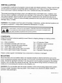
Noticq tq installer
Before installation and use - read all instructions and wamings.
Deliver this manual to the end user of this equipment.
Doc. No.: SAF205H $iren
v.
1
1
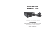
SAF205H Siren
GENERAL DESGRIPTION
The SAF205H Handheld Siren Amplifier is a premium 200W unit designed for single or dual 100W
speaker use with full lighting control. A remote handheld controller is connected to the amplifier
with a thin cable. The control head comes with a noise-canceling microphone for PA use and
push-button ovenide in all modes. lt contains illuminated buttons that change color to indicate
status. A potentiometer is also provided on the controller to adjust PA volume. The SAF2OSH also
includes 3 push buttons for primary lighting system oontrol and 4 auxiliary output push buttons;
each button is capable of 10 amps cunent. There are 3 primary operation modes: HandsFree,
Siren, and Radio with a Hom button Override and a Manual button Ovenide. The Radio and Siren
volume can be adjusted on the side of the siren amplifier.
A Hom Ring Transfer input is available for the conneciion to vehide hom ring or remote sritch for
hands-free siren operation. A Park Kill input is available for connection to a door sraritch, etc, to
stop siren tones when exiting the vehicle. A 1O-position DIP switch on the amplifierallorrrrs
selec{ion of various options. The handheld controller is backlighted with LED's for night visibility,
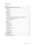
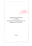
front view Handheld controller
front view (Light control connector)
SW4 8r S1rV5
LED INDICATOR
POTER N
ss9IStIt
o
JJJITA6'
o
UGHT CONTROT
LV BUTTONS
BB
MIC VOL
ADJUST
HORN
SIREN
mode
.R
vor
RAD
oo
yd..
RADIO
mode
UGHT CONTROL
AUX SW BUTTONS
side view (DlP switches)
SAF205H Siren v.1
SPECIFICATIONS
hput Vohage
Siren lnpd Gunent
Siren Standby Cunent
1
0-1
6VDC (negative grsund)
8.SAmps (@13.6VDC - single 1OqW speaker)
16Amps (@13.6VDC - dual 100W speakers)
Less than 150m4
t
3db
Audio Frequency
200H2- 10kHz
Siren Ouput Power
40 watts (@13.6vD0-single 100W speaker)
Siren Ouput Power
Siren Frequency
100 Watts RMS MAX. (14VDC - qingle 100W speaker)
200 Watts RMS
725H2
MAI
(14VDC - dual 1 00W speakers)
- 1465H2
wnll I vElp lnnnsenl
HORN
Tones/ Gycle Rates
Cycle Rates
Composite(Constant)
Operating Temp
-25' G to +60o C
| lzcPM I
tgOcPM
I
eSoCPM
I
nluo
eocnu
C15' F to +140" F)
3 push-button Mode switch (SIREN, HF, RADIO)'
Momentary push-button Horn switch.
Momentary push-button Manualffone toggle switch.
Siren Gonfols
ENA input (positive) to turn on unit.
HRT input programmable for positive or negative operation.
PKL input programrnablp for positive or negative latching operation.
Side DIP switch option selectors.
Light Confiols
3 push-button switch with position 3 siren activation and LED indicators.
4 - onloff lighted push-button switphes with replaceable legends,
I
outputs. (LV - 3 push buttons & $W - 4 push buttons)
Liglrt Outptrt Ragings
10A tuse on each of the
Siren Connectiong
(Removable
12-P Terminal Block)
Positive x 2, Negative x2, Speaker
Horn Ring Transfer, Park Kill.
Power
Light Gontol
Connections
ln
x2, Radio x2,Enable, Park
Kill,
2-position screw terrninal inputs.
LVl , LVz, L\13 (push buttons) 3-positioq scfe!4e!'minal oulputs.
SWI , S\r\fz, SW3, SW4 (push buttons) S-position screw terminal outPuts.
Size
Siren Amplifier 20.8cm x 1 8.8cm X 6.9crn Contoller: 5.6cm x 14cm x 3.3cm
Boxed Weight
2.5k9
SAF205H Siren v.1
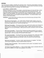
INSTALLATION
It is essential to installthe unit properly to ensure safe and reliable operation. Please read through
all instruc{ions thoroughly and carefully before installing the unit. Failure to follow these instructions could result in serious damage to the unit or vehicle and may void warranties.
The conect mounting end wiring is key to the effectiveness of SAF205H siren. lnstallers must
read and follow installation instructions and warnings in the manual from original manufacturer.
The vehicle operator should verify the siren system is fastened to the vehicle securely and is
functioning properly. Failure to follow all safety precautions and inslructions may c€use property
damage, injury, or deaih,
WARNING: The installer must have good knowledge of elec{ricity, vehicle elec{rical systems and
emergency equipment. Always seek professional assistance if in doubt.
WARNING
AO
Sound Hazard - Sound level from siren speaker (>120dBA @ 10 feet) may cause hearing damage.
Do not operate siren without adequate hearing protection for you and anyone in immediab vicinity.
(Ref. osHA 1910.95
br
occupational noise expmure guiderines)
CONTENTS
lnspect the product contents carefully to see if there is shipping damage or missing content.
Contents include:
1 pc
1pc
1 pc
-
1pc1pc1pc
-
(Amptifier)
Siren
Handheld controller with coil
Handheld Controller Mounting
12-Pin $iren lnput
2-Pin Light Control Power lnput
8-Pin Light control output
cord
Bracket
Connec{or
Connector
connec{or
1pc
1pc
1 pc
-
-
6' Extension Cabte
Extension cable connector
15 Button plate
1pc- Bufton Decals
1pc- User Manual
1pc
-
operation waming Label
Please contact supplier immediately if any component is missing or damaged.
MOUNTING
Mount the siren unit in a location that is not exposed direc{ly to weather elements such as the
driver compartment firewall, below the seat, or in the trunk; and away from any air bag deployment
areas. Mount the handheld controller in an area wtrere it can be easily accessed by the vehicle
operator, and not affect the vehicle the air bag. Be sure that all wiring harness conneclions are
made prior to connec{ing the hamess to the amplifier unil.
WARNING: Do nol interfere with the proper operation of the vehicle airbag deployment syslem.
Ensure to install 'Operation Waming Label" in the vehicle in an area that is clearly visible to
operators and passengers.
SAF205H Siren v.1
WRING
Use wires that are capable of handling the required cunenl. Route the wires properly to prevent
wear, overheating and interference with air bag deployment, Ensure that all conneclions are tight
and double check wiring before connecting to the vehicle battery.
ELECTRICAL CONNECTIONS
Electrical connections to the unit are made by using block plugs and screw terminals. Route
all wiring to the siren and secure onto block plug terminals, then plug onto the siren. The
plug can be easily removed without unwiring when the unit requires servicing. The power
supply for the fused amplifier (12-P plug) must be capable of delivering peak cunents up to
50A for adequate short circuit protec{ion and proper operation. lt is recommended to wire
directly to the vehicle battery.
WARNING: ensure that allwires are firmly secured onto the block plug, and plug is firmly
secured onto the siren.
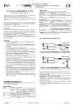
Wire Size and Termination -The'AMPLIFIER CONNECTIONS'diagram shows the
minimum size of the wires used for each connection, along with recommended lead color.
lf the wire is longer than 10 ft., use the next larger size.
- This serves as the power sadtch for the entire unit. Connec{ to a
positive circuit contnolled by the vehicle ignition switch, usually a termlnal at the vehicle
fuse panel. lt is not recommended to make permaneni power connection as this may drain
battery.
ENA lnput Connection
HRT Input Connection - The Horn Ring Transfer input allows ac{ivation by an exlemal
source of either the Hom or other func{ion. lt can be set for positive or negative writching,
see DIP-$W1-1 (HRT-N) underOPT|ON SWTCHES seclion.
FKL lnput Gonnection - The Park Kill input may be connec{ed to the vehicle door switctt
or other switching device to tum off any siren tone when activated. lt can be set for
positive or negative switching, see DIP-SW1-2 (PKLN) underOPT|ON SWTCHES
section.
Connec{ to radio output terminals or its speaker. The Radio
volume can be adjusted by using a small flat blade screwdriver.
RAD lnput Gonnection
-
Speaker Output Gonnection
connected in parallel.
-
Both connec{ions must be used. Two speakers may be
VID Output Connec,tion (Option) - A Mdeo Camera trigger output is activated when ever
the unit is in SIREN or HF mode. (Not available in this model).
SAF205H Siren v.1
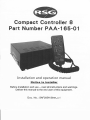
AMPLIFIER CONNECTIONS
3EF*e#*tCsHH
12-P Terminal Block Plug
#14 AWG RED x2
Use second lead
for dual speaker
#14AWG BLKx2
Use second lead
for dual speaker
dual speaker conhect + to +
#18 AWG BRN x2
(#16 AWG dual speaker)
ir il
ENA
#22 AWG ORG
Unit Enable (like an ON/OFF switch)
Connect to positive circuit (fuse panel)
controlled bv ionition or other swltch
VID
#22 AWG BLU Connectto camera
inplt
ADDED
DOOR SWITGTI
,f----exru
#22 AWG WHITE
+VDC Switching
example
-VDC Srvitching
example
MUst set
PKL N
option switch
Recommended
\Mre Size
Amps
Size
5-10
#16
1trl5
#14
1S25
25-40
4G60
#12
#10
MOMENTARY
FOOT SWITCH
#22 AWG YELLOW
-S-'Hnr
-VDG Switching
example
HRT
+VDC
l_
.-Lrl-il
HRT
=
+VDC
i __
@f
HRT
Must set HRT N
oSion switch'
#8
Use next larger siee
if longer than 1Oft.
RAD
#22 AWG GRAY x2 Connec't
tro output
jack, terminals, or speaker of radio
SAF205H Siren v.1
LIGHT CONTROL CONNECTIONS
E 5 E d, H
2-P Terminal
&P
Bloclt Plug
Terrpinal Block Plug
will accePt uP to #6 AWG for nPut
curreht tiigher than 40 AmPs
tt!
xo
E
=al/l
xo
xo
o
cl
=oo.
o
o
E
{o
E
IL
c
o
o
c{
l -T'
E
.E
-3
-3
E
(o
J
tt
G
3
tr
E
a
ttG
3
xt0
E
x
t10
x(ll
E
o
e
=a.J'
E
ts
E
o
o
t?
s
rr)
g
ul
a
i6
v)
!
6
_9
E
E
G
o
J
o
a
o
GI
_s
Hand held controller
Recomnlanded
tMre Size
Ampt
Size
5-10
#16
1G15
#14
1*25
#12
zffi
#10
40€0
#8
Use next larger size
if lortger than 1Oft'
NOTF: The controller
pf"eS or decals instal
plates, then install Pla
Y
butbn
button
SAF205H Siren-v
1
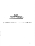
LIGHT CONTROL CONNECTIONS
- The power input for the light controls (the three LV switches and the four auxiliary
control switches) are separate from the power inputs for siren. This design helps prevent a
fault in one main clrcuit from afucting another main circuit.
Power
- Each light control output is fused and should be limited to 10 Amps.
Proper rated circuit breakers should be connec{ed between the power source and light
control power inputs. Refer to 'FUSE LOCATION" diagram for proper fuse location below.
Fuses/Breakers
WARNING: lmproper circult breakers or fuses can result in damage to the unit and/or vehicle.
FUSE LOCATION
(open siren top view)
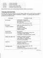
PROGRAMMING
Oncb the electrical connectiong are made and the power is available to the unit, each of the thrce
LV buftons and four auxiliary conlrol buttons are ready to be programmed. The programming
mode is entered by changing the DIP switch.
Follow these steps to program the unit:
Get into program mode.
1. Turn unit on with enable input.
2. Enier the program mode by tuming DIP-S\,\2-B (PRG) sritch on.
Set Auxiliary Control Buttons Operation (all LV buttons off)
1. With all LV buttons off, each auxiliary switch cunent operation program status is indiceted
on each push button. See the table belory for switch status definition.
2. Change button operation by momentarily pushing the auxiliary bufton.
LED showing
AUXILIARY button setting
Red Steady
PUSH on / PUSH
Red Flashing
MOMENTARY
TIMED MOMENTARY (10 seconds)
Red off
off (default)
NOTE: The Timed Momentary operation, typically used as a Gun Lock Timer, must begin
with push button 3. lf push button 3 is programmed as timed momentary, only
then push button 2 may be programmed also as a timed momentiary and so on.
-8-
Each LV bufton (LVl, LV2, LV3) may be programmed to automatically tum on any of the auxiliary
button controls (SW1-SV1/3) except Timed Momentary. These auxiliary button controls may still
be operated manually even if they were tumed on automatically. Each time the LV button
changes position, the combined auxiliary button controls are tumed on or off. \Men the LV button
is tumed ofl the entire auxiliary button controls tied to a position on the LV button is tumed off
while the other auxiliary buttons are unaffected,
Set LV buttons (LVl, LVz, LV3) and Auxiliary buttons Gombination
1. Activate desired LV button to program.
2. Press the desired auxiliary button to ctrange LED color to Red. Press the auxiliary button
again to change LED color to Green to remove from combination.
3. Once the LV buttons are programmed as desired, save and exit programming mode by
tuming DIP-SW2-8 (PRG) switch off.
NOTE: lf the unit is tumed off before the DIP-S\M-8 (PRG) stritch is tumed off, the new
programming will not be saved.
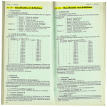
OPTION SWITCHES
Various options can be selected bY
tuming on or off DIP switches located
on the side of the siren. The DIP
SWITCH functions are described helow.
(see Appendix 1 for quick reference)
Dtp-SWt-l (HRT_N) HRT lnput Polarlty
DtP-Svrf2
DIP-SWI
ON
DlP
!E!!!![E
12
-
3 4 5 6 7
8
! ! r Ef l
fi.l
12 3 4 5 6 7I
The HRT input is normally ac'tivaled by a positive
voltage. Set switch on to activate with negative.
Dtp-$Wi-2 (PKL_NI PKL lnput Polarity
-
The PKL input is normally activated by a positive
voltage. Set switctr on to activate with negative.
DIP-SWI-3 (HILO)
-
HiLo tone replaces Phaset tone by setting this sivitch on.
-
Dlp-SWl.4 (PHASER_D)
D|P-SWI-5 (HORN_D)
-
Phaser/Hilo tones are disabled by setting this switch on.
Hom tone is disabled by setting this stvitch on.hart.
DIP-SWI€ {SIREN-SWI)
-
See "Siren Mode setlings" chart'
DIP€Wl-7 (SIREN-SW2) - See "Siren Mode settings" chart
SAF205H Siren v.1
DIP€W1-B (TA-D) - Wth this switch off, the handheld LED indicator operates in Traffic Anow
mode. \Mth this switch on, the Traffic Anow mode is disabled^
Press SW4
button:
Handheld conffoller LED lndicator
Wth DIP-SWl-8 off (Traffic Arrow mode)
lifith DIP-SW1-8 on (Regular mode)
1st Press
LED flashes right to left
Left LED on
Znd Press
LED flashes lefi to right
Right LED on
3rd Press
4th Press
LED flashes center out
Left and Right LEDs on
all LEDs off
all LEDs off
DIP€W2-l (HRT_HF-HORN) - Wfh this switch off, when in HF mode, Horn Ring wifl not
produce Hom tone. VMth thi$ srtritch on, when in HF mode, pressing Hom Ring for more than
0.5 seconds produces Hom tone.
DIP€W2-2 (HRT-STBY-DI
- With this switch off, when in standby (ie. no modes selected),
pressing Hom Ring or RAD button prcduces Hom tone. Wth this snitch on, Hom Ring willnot
produce Hom tone.
DIP€W2-3 (MAN_CHANGE)
- Wth this switch off, pressing MAN button momentarily
produces next tone. With this srilch on, pressing MAN button changes to next tone.
DIP€W2.4(SHORT-MAN) -Wth this switch off, MAN Siren tone slowly winds down when
released.
ltith this switch on, MAN Siren tone stops immediately when released.
DIP€W2-5 (LV_SW1)
-
See LIGHT CONTROLS seciion.
DIP€W24 (LV_SW2) - See LIGHT CONTROLS seclion.
DIP€W2-7 (AUTSR-D) - With this switch off, Siren tone is automatically activated when LV3
button is ac{ivated. Wth this switch on, Automatic Siren tone is disabled.
DIP€W2{
(PRG) -Tum this sMtch on to enter Programming mode; see PROGRAMMING
sedion.
SAF205H Siren v.1
OPERATIONS
POWER (ON/OFFI
The unit can be ac'tivated by applying positive voltage to the ENA terminal in the amplifier.
Normally, this is wired to the ignition switch of the vehicle; it can also be wired to another s$/itcfi
to act as ON/OFF. See "AMPLIFIER CONNECTIONS'diagram.
SIREN CONTROLS
0uP,
There are 5 buttons in the middle area of
the handheld controller dedicated for
primary operating modes of the siren.
Function modes
Modes
$tandby
(no mode selected)
+ MAN button
SILENT
MANUAL / SHORT MANUAL
see DIP-S\ E-4 SHORT MAN
HORN / SILENT
see DIP-S\M-2 HRT STBY
D
RAD]O
HORN / RADIO
See DIP'S\A/2-2 HRT STBY
D
RADIO
RADIO
tigger
Standard
HF
SILENT
SIREN
VVAIL
(see $iren Mode)
+ HRT
CYCLER
CYCLER
(see HF setings)
(see HF seftings)
YELP
YELP
(see Siren Mode)
(see Siren Modes)
HF -This is a standby mode dedicated for HRT (Hom Ring Transfer), Vvhen installing the unit, the
auxiliary input must be conneded to the horn ring or other srvitching device. Tap the hom ring or
MAN button once to aciivale Wail tone, then tap again to activate Yelp tone, and quickly tap the
hom ring twice to shut off siren tone. By setting DIP-S\M-1 on, pressing and holding the hom ring
will produce Hom tone until released, then the siren will retum to its previous siren tone.
HF settings
PHASER D on
PHASER_D otr
Press Horn Ring:
HRT tap once
(MAl,l press once)
HRT quickly tap twice
(MAN quickly tap twice)
HRT press +0.5 secs
HILO off
vltAlL->
YELP.> PHASER
HILO on
WAIL->
YELP-> HILO
HILO
off
I
HILO on
WAIL -> YELP
SILENT
SILENT (with DIP€!A2-1 ofi)
HORN (witrt DtP-s\AP-1 on)
SAF205H Siren v.1
SIREN - This bufton will activate Wail tone. \Mren pressing with MAN button together, it will
produce Yelp tone. See Siren Modes chart.
Siren Modes
SIREN S\All off
SIREN SW1 off
SIREN SW1 on
SIREN S\AE off
SIREN S\A2 on
SIREN S\^'2 -_
SIREN
WAIL
YELP
SIREN + MAN (oT HRT)
(w/ MAN_ CHANGE off)
YELP
SIREN + MAN (oT HRT)
WAIL / YELP
MODE
PHASER
(see PHASER settlngs)
YELP
/ PHASER
(see PHASER settings)
PHASER
(see PHASER settings)
YELP
PHASER / YELP
(see PHASER settings)
RADIO - This function amplifies the radio speaker input for re-broadcast outside the vehicle. lt is
also known as Radio Re-broadcaster, and no siren tones are available in this position. The Radio
Volume can be adjusted via potentiometer on the siren amplifier unit.
MAN - lt provides manual control of siren tone rise and fall while in Standby, HF or SIREN
modes. See "Function Modes" chart.
HORN - lt provides a simulated air-horn tone when pressed, and ovenides all siren tones. The
Hom tone may be disabled entlrely by setting the DIP-SW1-5 (HORN_D) option on. See OFTION
SWTCHES sec'tion.
PA - The noise-canceling microphone is used for public address operation. lt will ovenide any
siren mode when the button on the side is pressed. The volume can be adjusted through a pot
switch located in the upper right comer of the control head. lnsert a small, flat-blade screwdriver
into the pot switch; tum clockwise direction to increase the sound level.
HRT lnput (optional) - The Hom Ring Transfer input may be connec'ted to the hom ring or other
switching devices. Activating this input will produce Hom tone or other func{ions depending on the
push button position.
PKL lnput (optional) - The Park Kill input may be connec{ed to lhe vehicle door slrritch or other
switching device to tum off any siren tone when activated. The siren will remain deactivated until
the vehicle is shifted into gear or the door is closed and the siren is automatically reslarted,
SAF205H Siren v.1
LIGHT CONTROLS
The 3 LV buttons (LVl , LVz, LV3) in the top
area of the handheld controller are dedicated
for primary lighting functions. There are
additional 4 programmable on/off buttons for
auxiliary lighting or other devices.
@@
@@
@
@@
@@
LV buttons - The LV buttons can be set
to operate as a Progressive or Nonprogressive switching. There are four
modes available.
LV Button Modes
LV Button Modes:
hroDEl
MODE2
MODE3
LV SW1 off
LV SIAI2 off
L\LSW1 off
LV_SIM on
LV Shll on
LV S\Al2 off
LV1
MODE4
LV_SW1 on
LV S\lW on
LVl
LV1
LV1
LV1 . LV3
LV2
LV2
LV2
LV?. LV3
LV1 . LV2
LV3
LVl . LVz 'LV3
LV3
LV1 .. LVz . LV3
LV1 -LV2.LV3
Progrcssive/Non-progressive Switch - There are 4 different combination modes available. This is
configured by setting the DIP-SW 2-5 (LV-SW1) and DIP-SW 2-6 (LV-S\AP) option, At each of
the LV switches, it is possible to program the additionalAUX on/off buttons to be ac{ivated
together,
LV3 Button - Vvhen LV3 is switcfred on, the siren tone is automatically activated. This function
can be disabled by setting the DIP-SW-7 (AUTSR-D) option; see OPTION SWTCHES section.
VID Output Option - The VID output is ac'tivated vfienever the unil is in SIREN or HF modes.
(Available in future models),
AUXILIARY Buttons
- The 4 lighted on/off
buttons are for controlling other lighting
function$ or devices. SW1-SV\8 buttons can
be programmed for three operating modes
such as Push On/Off, Momentary, or Timed
momentary; see PROGRAMMING section.
SW4 button is designed to control SW4 and
SWs outputs, \A/hich is mainly used to control
the traffic affow functions.
@
fffii
t.*J
.AXt*TAeH'
tr89
@@
@@
@
1st Press
Activates ou$ut $tA/4
2nd Press
Activates output Sln 5
3rd Press
Activates ousuts
4th Press
Deactivates ouputs SW4 & SWs
sw4 & s\n/s
See DIP-SW1-8 OA_D) fot corresponcling Handheld controller LED indicator.
TROUBLE$HOOTING
SAF205H Siren has been designed to provide reliable quality service under the worst conditions.
lf encounter any dlfficultieb, check its installation or speakers. The following table repre$ents
problems and probable causes.
PROBLEM
POSSIBLE CAUSE
NO SOUND
Loose wires or connectors
Bad speaker or speaker wiring
Siren fuse down
PA volume in the lowest sound level
NO SIREN
High input voltage (greater than 16V)
PKL activated
PA button pressed
Speaker not connested
Defective spedker
TONE-PA WORK$
DISTORTED
SIREN SOUND
Bad speaker
Damaged or loose speaker housing or tip
Low voltage to siren amplifier
Loose wires or @nnectors at ENA or SPKR
SIREN VOLUME LOW
Speaker connected to wrong tap
Low voltage to siren amplifier
High tesistance in speaker wiring
PA volume in low position
WEAKPA
Microphone no held close to mouth
Defective microphone
Microphone loose connection
INTERMITTENT
High input voltage (greater than 16V)
Bad speaker driver
Unused wires touching vehicle ground or supply
SAF205H Siren_v.1
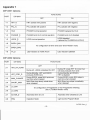
Appendix I
DIP-SW1 Options
FUNCTIONS
PORT
DIP€W1
OFF
ON
1-1
HRT
N
HRT activate with positive
HRT activate with negative
1-2
PKL
N
PKL activate with positive
PKL activate with negative
1-3
HILO
PHASER normal operation
PHASER replaced by HILO
14
PHASER D
PFIASER and HILO normal operation
PHASER and HILO disabled
1-5
HORN D
HpRN normal operation
HORN disabled
( replaced by PHASER/HILO|TELP)
1€
SIREN SW1
1-7
SIREN-SWz
1€
TA-D
for configuration of Siren tone (see "Siren Modes" chail)
LED lndicator Ctrrstant
LED lndicator as Traffic Arrow
DIP-SW? Options
PORT
DIP-SV/2
2-1
HRT-HF-HQRN
FUNCTIONS
OFF
ON
MAN CHANGE
During Standby, HRT and RADIO
produces HORN tone.
During SIREN, press MAN produces
next tone vvhen pressed
During HF, press HRT for more than
0.5 secs produces Horn tone
During Standby and RADIO,
HRT is disabled
During SIREN, press MAN skips to
next tone when pressed
24
sHoRT_MAN
MAN Siren tone slowly winds down
when released
MAN Siren tone stops imrnediately
when released
2-5
LV-SW1
24
LV-SW2
2-7
AUTSR-D
Automatic Siren at LV3
Automatic $iren Disabled at L\f,3
24
PRG
Operation Mode
Light Control Program Mode
During HF, HORN is disabled for HRT
2A
HRT-STBY-D
2-3
for configuration of Progresslve or Non-Progressive switching
(see "LV Button Modes" chart)
SAF205H Siren v
1