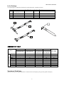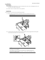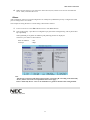
1
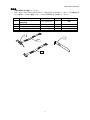
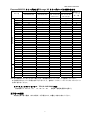
856-125671-002-02-3
大切に保管してください
N8117-01A
RS-232Cコネクタキット
取扱説明書
この度は、本製品をお買い上げいただきまして誠にありがとうございます。
本RS-232Cコネクタキットを取り付ける際には本体装置に添付の「使用上のご注意」に記載されて
いる内容をよく読んでご理解し、安全にご活用ください。
警告
安全上のご注意を無視する取り扱いを行うと、装置の故障、人体事故、火災・周囲の機器の損傷を
引き起こす原因となることがあります。
オプションの取り付け、取り外し時は電源プラグをコンセントから抜
き、外部装置と接続しているケーブルを外してください。
故障や感電する恐れがあります。
電源プラグを抜く
感電注意
分解禁止
本書に記載されている場合を除き、絶対に分解したり、修理・改造を
行ったりしないでください。装置が正常に動作しなくなるばかりでな
く、感電や火災の危険があります。
発火注意
感電注意
本製品は取り付ける装置により、使用するケーブルおよびPCI BRACKETが異なります。
本書の「Express5800/100シリーズおよびiStorage NSシリーズサーバとの組み合わせ」を参照し、
ケーブルおよびPCI BRACKETをご使用してください。
取り付け手順は本書および本体添付のユーザーズガイドを参照してください。
*856-125671-002-02O*
2010年7月 第3版
1
856-125671-002-02-3
構成品
本製品の構成品を確認してください。
また、次ページの「Express5800/100シリーズおよびiStorage NSシリーズサーバとの組み合わ
せ」を参照し、モデルに適合したケーブルおよびBRACKETをご使用してください。
項番
1
2
3
4
5
品名
RS-232Cコネクタキット
取扱説明書
RS-232Cケーブル(A)
RS-232Cケーブル(B)
PCI BRACKET(1)
PCI BRACKET(2)
指定
数量
備考
856-125671-002
1
本書
804-063264-020
804-062746-820
243-112122-001
243-112122-002
1
1
1
1
ケーブルに取付済
Full Height PCI用
4
5
2
3
2
856-125671-002-02-3
Express5800/100 シリーズおよび iStorage NS シリーズサーバとの組み合わせ
iStorage
Express5800
モデル名
2
RS232C ケーブル(A)
804-063264-020
3
RS232C ケーブル(B)
804-062746-820
○
-
-
○
○
-
○
○
○
○
○
○
-
-
-
-
○
○
-
-
-
-
-
-
-
○
○
○
○
-
-
-
-
○
○
-
-
○
-
-
-
-
-
-
○
○
○
○
-
-
○
○
○
○
○
○
○
-
-
-
-
○
○
○
110Ej
110Ek
110El
110Gb-C
110Gc
110Gc-C
110Gc-S
110Gd
110Gd-S
110Ge
110Ge-S
110Sc
120Eh
120Ei
120Gc
120Gd
GT110a
GT110a-S
GT120a
R120a-1
R120b-1
R120a-2
R120b-2
T110a
T120a-E
NS14PW
NS24P
NS28P
NS46P
NS48P
NS49P
NS480
4
PCI BRACKET(1)
243-112122-001
Low-Profile
-
-
-
-
-
-
○
-
○
-
○
○
-
-
-
-
-
○
-
○
○
○
○
-
-
○
○
○
-
-
-
○
5
PCI BRACKET(2)
243-112122-002
Full-Height
○
○
○
○
○
○
-
○
-
○
-
-
○
○
○
○
○
-
○
-
-
-
-
○
○
-
-
-
○
○
○
-
BIOS セット
アップでの
ポート名
B
B
B
B
B
B
B
B
B
B
B
B
B
B
B
B
B
B
A
A
A
A
A
B
A
B
B
B
B
B
B
A
※上記に記載されていないモデルに関しては、本体添付のユーザーズガイドを参照してください。
また組み合わせについて不明な点がございましたら、営業もしくはファーストコンタクトセンターに
お問い合わせください。
ファーストコンタクトセンター
受付時間/9:00~12:00,
TEL,03-3455-5800(代表)
13:00~17:00
月曜日~金曜日(祝祭日を除く)
第三者への譲渡
本製品を第三者へ譲渡(または売却)する場合には、本書を一緒にお渡しください。
3
856-125671-002-02-3
取り付け
1.準備確認事項
(1) 危険防止及び故障防止のため、作業を行なう際は本体装置の電源スイッチをOFFにし、電源プ
ラグをコンセントから抜いてください。
(2) 本体装置のユーザーズガイドを参照して取り付ける準備を行ってください。
2.取り付け
次の手順にしたがって取り付けてください。
1) 取り付けるスロットのスロットカバー固定ネジを外して、スロットカバーを取り外してくだ
さい。
外したスロットカバーは大切に保管してください。
2) ブラケットの先端がフレームのガイドに正しく差し込まれていることを確認し、しっかりと
取り付け、手順1で外したネジで固定してください。
本製品を取り付けようとする装置により、使用するケーブルおよびBRACKETが
異なります。
3ページ「Express5800/100シリーズサーバとの組み合わせ」を参照し、ケーブ
ル及び、BRACKETをご使用してください。
本書に記載されていないモデルに関しては、本体添付のユーザーズガイドを参
照し、ケーブルおよびBRACKETをご使用してください。
4
856-125671-002-02-3
3) 他のPCIボードに緩衝しないようケーブルをフォーミングしてマザーボード上のCOMコネクタ
に接続してください。ケーブルを接続する場合、コネクタの極性キーを合わせて誤接続しな
いよう注意してください。
COMコネクタの位置は以下を参照してください。他の装置ではユーザーズガイドを参照してコ
ネクタの位置を確認してください。
Express5800/110Sc、110Gc-S
110Gc、110Gb-C
iStorage/NS24P、NS14PW、NS34P
Express5800/110Ej
iStorage/NS46P
Express5800/120Ei、120Gd
Express5800/120Eh
Express5800/T120a-E、GT120a
Express5800/R120a-1,R120b-1,
R120a-2,R120b-2
iStorage NS480
Express5800/110Gd、110Gd-S
110Gc-C
iStorage/NS26P
Express5800/110El,T110a
iStorage NS48P,NS49P
5
856-125671-002-02-3
Express5800/110Ek
iStorage NS47P
4) 取り外したスロットカバーや工具、ネジ等が装置内部に残っていないことを確認して装置を
組み立ててください。
3.その他
本体装置によっては本製品を取り付けた後、BIOSセットアップメニューでCOMポートの設定が必要
な装置があります。以下に設定が必要な装置の設定方法例を記載致します。
1) 本体装置の電源を入れ、POST画面で[F2]キーを押してBIOSセットアップメニューを起動し
ます。
2) 「Advanced」 - 「I/O Device Configuration」または「Serial Port Configuration」 メニュ
ーで 「Serial Port B」 を 「Enabled」 に設定(もしくは設定されていることを確認)してく
ださい。
「Enabled」 に設定すると「Base I/O Address」、「Interrupt」 のメニューが追加されます。
Default設定では
Base I/O Address
:2F8
Interrupt
:IRQ 3
となります。
注)本体装置によっては本製品による増設シリアルポートが「Serial Port A」となります。
(3ページの「Express5800/100シリーズサーバとの組み合わせ」を参照してください。)
なお、設定方法の詳細は本体装置に添付のユーザーズガイドを参照してください。
以上
6
856-125671-002-02-3
Keep this manual in safe place.
N8117-01A RS-232C Connector Kit
User's Guide
Thank you very much for purchasing the N8117-01A RS-232C Connector Kit.
Before installing the RS-232C connector kit, carefully read the "Notes on Use" described in the User's Guide
coming with your server to fully understand them.
WARNING
Use of the server ignoring the Notes on Safety may cause malfunctions or failures of the server,
personal injury, fire, and/or damages of surrounding devices to occur.
Unplug the
power cord
Electric shock
Do not
disassemble
Flammable
Make sure to power off the server and unplug the power cord from a power
outlet and disconnect all the cables connected with the external devices
before installing/removing any optional device to/from the server. Failure to
follow this instruction may cause an electric hazard or failure of the server.
Do not disassemble, repair, or modify the product unless the procedure is
described in this manual. Failure to follow it may cause the server to
operate incorrectly, people to be electrically shocked, or fire to occur.
Electric shock
Imprtance
The cable and PCI BRACKET that uses this product with the installed device are different.
Please use the cable and PCI BRACKET referring to "Combination with the NEC Express5800/100
series server" in this book.
Please refer to the user's guide of this book and the main body attachment for the installation procedure.
7
856-125671-002-02-3
In the Package
Your packing box contains the items shown in the table below. Check these items.
No.
1
2
3
4
5
Item
RS-232C Connector Kit
User's Guide
RS-232C cable(A)
RS-232C cable(B)
PCI bracket (1)
PCI bracket (2)
Specification
856-125671-002
Quantity
804-063264-020
804-062746-820
243-112122-001
243-112122-002
1
1
1
1
1
Remarks
This manual
Attached to the cable
For Full-height PCI board
4
5
2
3
COMBINATION TABLE
NEC Express5800
Model
110Ej
110Ek
110Gd
120Eh
120Ei
R120a-1
R120b-1
R120a-2
R120b-2
T120a-E
2
RS232C Cable(A)
804-063264-020
3
RS232C Cable(B)
804-062746-820
○
-
○
-
-
-
-
-
-
-
-
○
-
○
○
○
○
○
○
○
4
PCI BRACKET(1)
243-112122-001
Low-Profile
-
-
-
-
-
○
○
○
○
-
5
PCI BRACKET(2)
243-112122-002
Full-Height
○
○
○
○
○
-
-
-
-
○
BIOS Setup
Port name
Transfer to Third Party
When you transfer (or sell) the RS-232C Connector Kit to a third party, also give this guide to the party.
8
B
B
B
B
B
A
A
A
A
A
856-125671-002-02-3
Installation
Preparation
1.
To avoid a hazard and failure, be sure to turn off the power of the server, and unplug the power cord
from power outlet before starting work.
2.
Refer to the User's Guide of the server for preparation.
Installation
Install the RS-232C Connector Kit in the following procedures.
1.
Remove the screw from the slot to install the connector kit, and remove the slot cover.
IMPORTANT: Keep the removed slot cover for future use.
2.
Install the bracket after making sure that the end of bracket is firmly engaged with the frame guide.
Secure the bracket with the screw removed in Step 1.
NOTE: You must select the proper PCI bracket depending on the server on which
the connector is to be installed.
At the shipment, the PCI bracket for low profile PCI is equipped with RS-232C
cable. If you are going to install the connector to the PCI slot of full height, use the
PCI bracket for hull-height PCI.
9
3.
856-125671-002-02-3
Route the cable so that it does not disturb any other PCI boards, and connect the cable to COM
connector on mother board.
Confirm the position of the connector on MB referring to the figure below.
NEC Express5800/110Ej
NEC Express5800/120Eh
NEC Express5800/120Ei
NEC Express5800/T120a-E
NEC Express5800/R120a-1,R120b-1,
R120a-2,R120b-2
NEC Express5800/110Gd
NEC Express5800/110Ek
10
856-125671-002-02-3
4.
Make sure that the slot cover which have been removed, tool, and/or screws are not left inside the
server. Then, reassemble the server.
Others
After installation, some server needs configuration for COM port by BIOS Setup Utility. Configure the COM
port according to the User's Guide.
The example of setting the device to need setting is described as follows.
1.
Power on the server. Press F2 on POST screen to start BIOS SETUP.
2.
Select [Advanced] → [I/O Device Configuration] or [Serial Port Configuration], and set [Serial Port
B] to [Enabled].
When [Enabled] is set, [Base I/O Address] and [Interrupt] menus are displayed.
The factory-set values are shown below.
Base I/O Address
: 2F8
Interrupt
: IRQ 3
Note
The increase serial port with this product becomes "Serial Port B" according to the main body
device. (Please refer to the correspondence table of next page. )
Please ..main body device.. refer to an attached user's guide for details of the setting method.
3rd Printing, July 2010
11