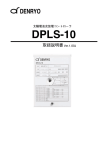
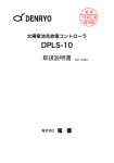
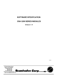
1
M
AX
/M
IN
Electronic Test
Instruments &
Power Supplies
AC
+H
z
AC
+D
C
CAL
AUT
O/M
AN
DC mV
DCV
AC
10A
ACA
DC mV
AC mV
DCV
ACV
CAL
AC
mV
Ω
・ )) )
MAX/MIN
dBm
REL
AUTO/MAN
ACV
DC 10A
AC 10A
AC+Hz
DCAd
ACA
AC+DC
Bm
HOLD
・)
))
Ω
L
LD
HO
RE
DC 10A
DCA
Parts No. Z1-002-480, IA002673
- 保 証 この製品は、菊水電子工業株式会社の厳密な試験・検査を経て、その
性能は規格を満足していることが確認され、お届けされております。
弊社製品は、お買上げ日より1年間に発生した故障については、無
償で修理いたします。
但し、次の場合には有償で修理させていただきます。
1. 取扱説明書に対して誤ったご使用およびご使用上の不注意による
故障、損傷。
2. 不適当な改造・調整・修理による故障および損傷。
3. 天災・火災・その他外部要因による故障および損傷。
なお、この保証は日本国内に限り有効です。
This warranty is valid only in Japan.
All or any parts of this manual may not be reproduced in any forms, without express
written permission of Kikusui Electronics Corporation.
The contents of this manual are subject to change without notice.
© 2001 Copyright Kikusui Electronics Corporation.
All rights reserved.
取扱説明書の一部または全部の転載、複写は著作権者の許諾が必要です。
製品の仕様ならびに取扱説明書の内容は予告なく変更することがあります。
Copyright© 2001 菊水電子工業株式会社
Printed in Japan
安全記号について
製品を安全にご使用いただくため、また安全な状態に保つために取扱
説明書および製品本体には、次の記号を表示しています。記号の意味
をご 理解いただき、各項目 をお守りくださ い。
(製品によ っては使用
されていない記号もあります。)
または
危険
DANGER
1 000 V以上の高電圧を取り扱う箇所を示します。
不用意に触れると、感電し死亡または重傷を負う恐れがあ
ります。触れる必要がある場合は、安全を確保してから作
業してください。
この表示を無視して、誤った取り扱いをすると、人が死亡
または重傷を負う危険が切迫して生じることが想定される
内容を示します。
警告 この表示を無視して、誤った取り扱いをすると、人が死亡
WARNING または傷害を負う可能性が想定される内容を示します。
注意
COUTION
この表示を無視して、誤った取り扱いをすると、物的損害
のみの発生が想定される内容を示します。
禁止する行為を示します。
危険・警告・注意個所または内容を知らせるための記号で
す。本製品上にこのマークが表示されている場合は、本取
扱説明書の該当箇所を参照してください。
保護導体端子を示します。
シャシ(フレーム)端子を示します。
DME1500
安全記号について J-1
ご使用上の注意
火災・感電・その他の事故・故障を防止するための注意事項です。内
容をご理解いただき、必ずお守りください。
ration
Ope
al
Manu
使用者
• 本 製品は、電気的 知識(工業高 校の電気 系の学科卒 業程
度)を有する方が取扱説明書の内容を理解し、安全を確認
した上でご使用ください。
• 電気的知識の無い方が使用する場合は、人身事故につなが
る可能性がありますので、必ず電気的知識を有する方の監
督のもとでご使用ください。
• 本製品は、一般家庭・消費者向けに設計、製造された製品
ではありません。
用 途
• 製品本来の用途以外にご使用にならないでください。
Line
Voltage
入力電源
• 必ず定格の入力電源電圧範囲内でご使用ください。
• 入 力電源の供 給には、付属の 電源コード をご使用く ださ
い。ただし、入力電源電圧を切り換え可能な製品、および
100V 系 /200V 系を切り換えなしで使用可能な製品は、入
力電 源電圧によ って付属の 電源コード を使用でき ない場
合があります。その場合は適切な電源コードを使用してく
ださい。詳しくは、取扱説明書の該当ページを参照してく
ださい。
ヒューズ
• 外面にヒューズホルダが配置されている製品は、ヒューズ
を交換することができます。ヒューズを交換する場合は、
本製品に適合した形状、定格、特性のヒューズをご使用く
ださい。詳しくは、取扱説明書の該当ページを参照してく
ださい。
J-2 ご使用上の注意
DME1500
カバー
• 機器内部には、身体に危険を及ぼす箇所があります。外面
カバーは、取り外さないでください。
L N G
設 置
• 本製品を設置する際は、本取扱説明書記載の「設置に関す
る注意事項」をお守りください。
• 感電防止のため保護接地端子は、電気設備基準 -D 種以上
の接地工事が施されている大地アースへ、
必ず接続してく
ださい。
キャスタ止めをして
• キャスタ付き製品を設置する場合は、
ください。
移 動
• 電源スイッチを OFF にし、配線ケーブル類をすべて外し
てから移動してください。
• 質量(重量)が 20kg を越える製品は、二人以上で作業し
てください。製品の質量(重量)は、製品の後面または取
扱説明書の仕様欄に記載されています。
• 傾斜や段差のある場所は、
人数を増やすなど安全な方法で
移動してください。また、背の高い製品は、転倒しやすい
ので力を加える場所に注意して移動してください。
• 製品を移動する際は、必ず取扱説明書も添付してください。
DME1500
ご使用上の注意 J-3
?
eck
Ch
操 作
• ご使用の前には、必ず入力電源やヒューズの定格および入
力電 源ケーブル などの外観 に異常がな いかご確認 くださ
い。確 認の際は、必ず 電源プラ グをコン セントから 抜く
か、給電を遮断して作業してください。
• 本製品の故障または異常を確認したら、ただちに使用を中
止 し、電源プラグ をコンセ ントから 抜いてくだ さい。ま
た、修理が終わるまで誤って使用されることがないように
してください。
• 出力配線または負荷線などの電流を流す接続線は、電流容
量に余裕のあるものをお選びください。
本製品を分解・改造しないでください。
改造の必要がある
•
場合は、購入元または当社営業所へご相談ください。
保守・点検
• 感電事故を防止するため保守・点検を行う前には、必ず電
源プラグをコンセントから抜くか、給電を遮断してくださ
い。
• 製品の性能、安全性を維持するため定期的な保守、点検、
クリーニング、校正をお勧めします。
調整・修理
• 本製品の内部調整や修理は、当社のサービス技術者が行い
ます。調整や修理が必要な場合は、購入元または当社営業
所へご依頼ください。
J-4 ご使用上の注意
DME1500
目次
安全記号について- - - - - - - - - - - - - - - - - - - - - - - - - - - - - - - - - - - - - - - - J-1
ご使用上の注意 - - - - - - - - - - - - - - - - - - - - - - - - - - - - - - - - - - - - - - - - - J-2
はじめに
特徴 - - - - - - - - - - - - - - - - - - - - - - - - - - - - - - - - - - - - - - - - - - - J-7
第1章
セットアップ
1.1
開梱時の点検 - - - - - - - - - - - - - - - - - - - - - - - - - - - - - - - - - - - - J-9
1.2
設置場所の注意 - - - - - - - - - - - - - - - - - - - - - - - - - - - - - - - - - J-10
1.3
移動時の注意 - - - - - - - - - - - - - - - - - - - - - - - - - - - - - - - - - - - J-11
1.4
入力電源とヒューズの確認 - - - - - - - - - - - - - - - - - - - - - - - - - J-12
1.5
電源コードの接続 - - - - - - - - - - - - - - - - - - - - - - - - - - - - - - - - J-13
1.6
接地について - - - - - - - - - - - - - - - - - - - - - - - - - - - - - - - - - - - J-14
第2章
2.1
2.2
操作方法
本器を使用する前に - - - - - - - - - - - - - - - - - - - - - - - - - - - - - - J-15
2.1.1
ウォームアップ - - - - - - - - - - - - - - - - - - - - - - - - - - - - - - - - J-15
2.1.2
オーバレンジ表示 - - - - - - - - - - - - - - - - - - - - - - - - - - - - - J-15
2.1.3
入力過負荷保護 - - - - - - - - - - - - - - - - - - - - - - - - - - - - - - - J-15
2.1.4
コモン端子への入力接続 - - - - - - - - - - - - - - - - - - - - - - - - J-16
基本操作 - - - - - - - - - - - - - - - - - - - - - - - - - - - - - - - - - - - - - - J-16
2.2.1
電圧測定(DCV、ACV、DCmV、ACmV)- - - - - - - - - - - - J-16
2.2.2
電流測定(DCA、DC 10A、ACA、AC 10A)- - - - - - - - - - J-16
2.2.3
抵抗(Ω)
、静電容量(
)、
導通性ブザー(•))))の測定 - - - - - - - - - - - - - - - - - - - - - - J-17
2.2.4
ダイオードテスト(
)測定 - - - - - - - - - - - - - - - - - - J-17
2.2.5
dBm 測定 - - - - - - - - - - - - - - - - - - - - - - - - - - - - - - - - - - - - J-17
2.2.6
AC+Hz 測定 - - - - - - - - - - - - - - - - - - - - - - - - - - - - - - - - - - J-18
2.2.7
AC+DC 測定 - - - - - - - - - - - - - - - - - - - - - - - - - - - - - - - - - - J-18
2.2.8
MAX/MIN 測定- - - - - - - - - - - - - - - - - - - - - - - - - - - - - - - - J-18
2.2.9
REL 測定 - - - - - - - - - - - - - - - - - - - - - - - - - - - - - - - - - - - - J-18
2.2.10 HOLD 測定 - - - - - - - - - - - - - - - - - - - - - - - - - - - - - - - - - - J-18
DME1500
目次 J-5
第3章
3.1
測定手法
dBm 測定手法 - - - - - - - - - - - - - - - - - - - - - - - - - - - - - - - - - - - J-19
3.2
真の実効値測定- - - - - - - - - - - - - - - - - - - - - - - - - - - - - - - - - - J-19
3.3
AC+DC 測定 - - - - - - - - - - - - - - - - - - - - - - - - - - - - - - - - - - - - J-21
3.4
クレストファクタ - - - - - - - - - - - - - - - - - - - - - - - - - - - - - - - - J-21
第4章
各部の名称と機能
4.1
前面パネル - - - - - - - - - - - - - - - - - - - - - - - - - - - - - - - - - - - - - J-23
4.2
後面パネル - - - - - - - - - - - - - - - - - - - - - - - - - - - - - - - - - - - - - J-26
第5章
保守
5.1
クリーニング - - - - - - - - - - - - - - - - - - - - - - - - - - - - - - - - - - - J-27
5.2
点検 - - - - - - - - - - - - - - - - - - - - - - - - - - - - - - - - - - - - - - - - - - J-27
5.3
校正 - - - - - - - - - - - - - - - - - - - - - - - - - - - - - - - - - - - - - - - - - - J-27
5.4
保護ヒューズの交換 - - - - - - - - - - - - - - - - - - - - - - - - - - - - - - J-28
第6章
仕様
6.1
直流電圧(DCV)- - - - - - - - - - - - - - - - - - - - - - - - - - - - - - - - - J-29
6.2
真の RMS 交流電圧
6.3
交流電圧(ACV)レンジでの周波数測定 - - - - - - - - - - - - - - - J-30
6.4
直流電流- - - - - - - - - - - - - - - - - - - - - - - - - - - - - - - - - - - - - - - J-31
6.5
真の RMS 交流電流
6.6
交流電流(ACA)レンジでの周波数測定 - - - - - - - - - - - - - - - J-32
6.7
抵抗 - - - - - - - - - - - - - - - - - - - - - - - - - - - - - - - - - - - - - - - - - - J-32
6.8
静電容量- - - - - - - - - - - - - - - - - - - - - - - - - - - - - - - - - - - - - - - J-33
6.9
ダイオードチェック - - - - - - - - - - - - - - - - - - - - - - - - - - - - - - J-33
または真の RMS 交流+直流電圧 - - - - - - - - - - - - - - - - - - - - - J-30
または真の RMS 交流+直流電流 - - - - - - - - - - - - - - - - - - - - - J-31
6.10 導通性ブザー - - - - - - - - - - - - - - - - - - - - - - - - - - - - - - - - - - - J-33
6.11 環境 - - - - - - - - - - - - - - - - - - - - - - - - - - - - - - - - - - - - - - - - - - J-34
6.12 一般事項- - - - - - - - - - - - - - - - - - - - - - - - - - - - - - - - - - - - - - - J-34
J-6 目次
DME1500
はじめに
DME1500 は、汎用アプリケーション向けに設計された、50000 カウン
トの優れた性能をもつ、携帯型ベンチタイプのデュアルディスプレイ
デジタルマルチメータです。デュアルディスプレイによって、測定中
の入力信号の 2 つの機能を表示することができます。
特徴
■ 50000 カウント
■ 多機能: ACV、DCV、ACA、DCA、R、C、Hz、導通性ブザー、ダイ
オードテスト、 MAX/MIN、 REL、 HOLD、 dBm
■ デュアルディスプレイによる ACV と Hz、あるいは DCV(ACV)と
dBm の表示
■ マニュアルレンジまたはオートレンジ
■ 0.03% の DCV 確度
■ 10A の高電流レンジ
■ 1200V の高電圧レンジ
■ AC または AC + DC の真の実行値 (True RMS )
DME1500
はじめに J-7
J-8 はじめに
DME1500
第1章
1.1
セットアップ
開梱時の点検
■ 開梱
製品がお手元に届きしだい付属品が正しく添付されているか、また
輸送中に損傷を受けていないかをお確かめください。
万一、損傷または不備がございましたら、お買い上げ元または当社営
業所にお問い合わせください。
付属品
品 名
数量
1
テストリード
1
2
電源コード
1
3
AC プラグアダプタ (3P-2P) 国内仕様のみ
1
4
AC 入力用ヒューズ 0.08A(T) 200V 系入力用
1
取扱説明書
1
5
チェック
■ 梱包
注意 ・ 製品を輸送する場合には、必ず専用の梱包材を使用してくださ
い。梱包材が必要な場合には、お買い上げ元または当社営業所
にお問い合わせください。
・梱包時、電源コードおよび接続ケーブルなどは、はずしてくだ
さい。
DME1500
セットアップ J-9
1.2
設置場所の注意
本製品を設置する際の注意事項です。必ず守ってください。
■ 可燃性雰囲気内で使用しないでください。
爆発や火災を引き起こす恐れがありますので、アルコールやシンナー
などの可燃物の近く、
およびその雰囲気内では使用しないでください。
■ 高温になる場所、直射日光の当たる場所を避けてください。
発熱・暖房器具の近く、および温度が急に変化する場所に置かないで
ください。
使用温度範囲:0 ℃∼ +50 ℃
保存温度範囲:-40 ℃∼ +70 ℃
■ 湿度の高い場所を避けてください。
湯沸かし器、加湿器、水道の近くなど湿度の高い場所には置かないで
ください。
湿度範囲は、「6.11 環境」を参照してください。
使用湿度範囲内でも結露する場合があります。その場合には、完全に
乾くまで本製品を使用しないでください。
■ 腐食性雰囲気内に置かないでください。
腐食性雰囲気内や硫酸ミストの多い環境に設置しないでください。製
品内部の導体腐食やコネクタの接触不良などを引き起こし、誤動作や
故障の原因となり、火災につながることがあります。
■ ほこりや塵の多い場所に置かないでください。
ほこりや塵の付着により感電や火災につながることがあります。
■ 風通しの悪い場所で使用しないでください。
熱がこもり火災の原因になりますので、本製品の周囲に充分な空間を
確保してください。
■ 本製品の上に物を乗せないでください。
特に重たい物を乗せると、故障の原因になります。
■ 傾いた場所や振動がある場所に置かないでください。
落ちたり、倒れたりして破損やけがの原因になります。
■ 周囲に強力な磁界や電界のある場所で使用しないでください。
誤動作により、感電や火災につながることがあります。
J-10 セットアップ
DME1500
1.3
移動時の注意
本製品を設置場所まで移動する、または本製品を輸送する際には、次
の点にご注意ください。
■ POWER スイッチを OFF にしてください。
POWER スイッチを ON にしたまま移動すると感電や破損の原因にな
ります。
■ 接続されているすべての配線を外してください。
ケ ーブル 類を外さ ないで移 動すると 断線や 転倒によ るけがの 原因に
なります。
■ 本製品を輸送するときは、必ず専用の梱包材をご使用ください。
専 用の梱 包材を使 用しない と輸送中 の振動 や落下な どによる 破損の
原因になります。
梱包材が必要なときは、お買い上げ元または当社営業所にお問い合わ
せください。
DME1500
セットアップ J-11
1.4
入力電源とヒューズの確認
本器は表 1-1 に示した 3 つの入力電源電圧範囲から 1 つを選択して使
用することができます。工場出荷時の設定が本器へ供給する電圧に適
しているか確認してください。また、入力ヒューズは入力電源電圧範
囲に適した定格のヒューズを使用する必要があります。
警告 ・感電を避けるため、ヒューズを確認または交換する前に、必ず
電源コードのプラグを抜いてください。
注意 ・ヒューズは、本器に適合した形状、定格、特性のヒューズを使
用してください。定格の違うヒューズやヒューズホルダを短絡
して使用すると本器を損傷します。
入力電源電圧範囲の確認(変更)
、および入力ヒューズの確認(交換)
は、以下の手順に従ってください。
1.
[POWER] スイッチを OFF にし、電源コードのプラグを抜いてく
ださい。
2.
図 1-1 のように、ヒューズホルダを外します。
3.
LINE VOLTAGE 表で実装されているヒューズの定格および溶断
特性を確認してください。違っている場合は交換してください。
表 1-1 LINE VOLTAGE
LINE VOLTAGE RANGE
FREQUENCY
85 - 115V
102 - 138V
196 - 264V
J-12 セットアップ
50/60Hz
FUSE(250V)
0.1A(T)
VA MAX
8
0.08A(T)
DME1500
4.
LINE VOLTAGE 表で使用する入力電圧を確認し、電圧セレクタ
を▼に合わせて差し込んでください。
合わせマーク
FUSE
電圧セレクタ兼ヒューズホルダ
120
100
AC LINE
230
マイナスドライバの先端をここに入れてカバーを抜き取ります。
使用する入力電圧を▼マークに合わせてから押し込みます。
(図の位置は、入力電圧85∼115Vの時です)
図 1-1
1.5
ヒューズホルダの外し方
電源コードの接続
警告 ・ 図 1-2 に示した 3 極プラグ付電源コード(100V 系入力電源電
圧用の製品に添付されます)の定格電圧は AC125V です。も
し、入力電源電圧範囲を 200V 系に切り換えて本器を使用する
場合は、
この電源コードを適切な電源コードと交換してください。
この電源コードは定格電圧
AC125V です。
図 1-2
付属の 3 極プラグ付き電源コード
以下の手順で接続してください。
1.
[POWER] スイッチを OFF にします。
2.
後面パネルの AC LINE コネクタに電源コードを接続します。
3.
電源コードのプラグをコンセントに差し込みます。
DME1500
セットアップ J-13
1.6
接地について
警告 ・接地を行わないと、感電する恐れがあります。
・接地は電気設備技術基準に基づく D 種以上の接地工事が施さ
れている部分へ行わなければなりません。
注意 ・接地を行わないと、外来ノイズにより誤動作したり、本製品か
ら発生するノイズが大きくなったりすることがあります。
安全のために接地(アース)は必ず行ってください。
本製品を接地するには、次の 2 種類の方法があります。必ずいずれか
の方法で確実に接地してください。本製品に接地端子はありません。
1.
電源コードに付属する 3 極 -2 極変換アダプタをはずして、電源
コードを接地工事が施された 3 極電源コンセントに接続する。
2.
電源コードに 3 極 -2 極変換アダプタを付けたまま、2 極電源コ
ンセントに接続し、アダプタの GND 線(緑色)を接地する。
接地端子
J-14 セットアップ
DME1500
第2章
2.1
操作方法
本器を使用する前に
2.1.1 ウォームアップ
定格確度を得るためには、本器を 30 分間ウォームアップする必要が
あります。
2.1.2 オーバレンジ表示
入力が、選択されたレンジのフルスケールを越えると、オーバレンジ
になります。本器は、ディスプレイに「− OL −」を表示させて入力
がオーバレンジしていることを示します。
2.1.3 入力過負荷保護
最大許容入力は表 2-1 に示す通りです。この表に従って測定を進めて
ください。
表 2-1
機能
レンジ
最大入力
DCV
5V ∼ 1200V
1200V DC または 1200V AC ピーク
ACV(AC+DC)
5V ∼ 1000V
1000V rms 連続
DC,ACmV (AC+DC)
500mV
450V DC または 450V AC ピーク
DCA,ACA(AC+DC)
500µA ∼ 2A
ヒューズで保護:2A、 250V
DC,AC10A(AC+DC)
10A
ヒューズによる保護なし
Ω
全レンジ
450V DC または 450V AC ピーク
静電容量
全レンジ
450V DC または 450V AC ピーク
警告 • 表 2-1 に示す最大許容入力を越える電圧を印加すると、感電お
よび本器が損傷するおそれがあります。最大許容入力電圧を超
えるような使い方はしないでください。
DME1500
操作方法 J-15
2.1.4 コモン端子への入力接続
警告 • コモン端子とアースグランド間の対接地電圧(コモンモード電
圧)が 500V DC または AC ピークを越えると、感電および本
器が損傷するおそれがあります。コモンモード電圧が 500V DC
または AC ピークを越えるような使い方はしないでください。
2.2
基本操作
2.2.1 電圧測定(DCV、ACV、DCmV、ACmV)
1.
ファンクションキーを押して希望する機能を選択します。
2.
[ ] または [ ] を押して希望するレンジに設定します(入力値
が不明 の場合 には、必ず 最高レ ンジか ら設定 してく ださい)。
[AUTO/MAN]キーを押 して、マニュ アルレン ジあるいは オー
トレンジを選択します。
3.
テストリードを本器の「V」、
「COM」入力端子に接続します。
4.
テストリードを測定点に接続し、表示値を読み取ります。
注記
• 1000V DC の高電圧を測定後、 100µV を測定するとエラーが発
生する場合があります。この場合は、最大 1 分間待ってから低
いレベルの測定を行います。
2.2.2 電流測定(DCA、DC 10A、ACA、AC 10A)
1.
ファンクションキーを押して希望する機能を選択します。
2.
[ ] または [ ] を押して希望するレンジに設定します(入力値
が不明 の場合 には、必ず 最高レ ンジか ら設定 してく ださい)。
[AUTO/MAN]キーを押 して、マニュ アルレン ジあるいは オー
トレンジに変更します。
3.
テストリードを本器 の「2A」または「10A」と「COM」入力端
子に接続します。
4.
テストリードを測定点に接続し、表示値を読み取ります。
J-16 操作方法
DME1500
2.2.3 抵抗(Ω)、静電容量(
の測定
)、導通性ブザー( •))))
1.
ファンクションキーを押して機能を選択します。
2.
[ ]または [ ]を押して希望するレンジにします。
[AUTO/MAN]
キーを 押して、マニュアルレン ジあるいはオート レンジに変更
します。
3.
テストリードを本器の「Ω、
」
、および「COM」入力端子に
接続します。
4.
テストリードを測定点に接続し、表示値を読み取ります。
2.2.4 ダイオードテスト(
)測定
1.
ファンクションキーを押して機能を選択します。
2.
テストリードを本器の「
3.
図 2-1 に示すように、テストリードを半導体接合部(ダイオード
あるいはトランジスタ)に接続し、表示値を読み取ります。
"
"
端子に接続
」、
「COM」入力端子に接続します。
"COM"
端子に接続
図 2-1
2.2.5 dBm 測定
この機能は、電圧測定値を dBm 値に変換します。dBm 測定機能は、
電圧機能(AC 電圧、DC 電圧 AC+DC 電圧)が選択されている場合に
のみ選択することができます。[SHIFT] キーを押し、
[dBm]キーを押
すと、ディスプレイ 2 はディスプレイ 1 に示される電圧値に相当する
dBm 値を示します。
たとえば、MAX モードで電圧を測定しているときに [SHIFT] キーを
押し、[dBm]キーを押すと、最大値が dBm 値に変換されます。dBm
機能を解除するには、再度 [SHIFT] キーを押し、[dBm]キーを押し
ます。dBm モードと AC+Hz モードは、同時に選択することはできま
せん。本器の標準基準インピーダンスは 600Ω です。
DME1500
操作方法 J-17
2.2.6 AC+Hz 測定
この機能は、AC レンジが選択されている場合にのみ選択することが
できます。[SHIFT]キーを押し、そして[AC+Hz]キーを押します。
すると、ディスプレイ 2 は感度よりも高い入力信号の周波数を示しま
す。周波数測定は、MAX/MIN、REL、HOLD モードに依存しません。
このモードでは、本器の読取速度が通常の速度よりも低下する場合が
あります。
AC+Hz 機能を解除するには、再度 [SHIFT] キーを押し、
[AC+Hz]キー
を押します。dBm モードと AC+Hz モードは、同時に選択することは
できません。
2.2.7 AC+DC 測定
この機能は、電圧機能か電流機能が選択されている場合にのみ選択す
ることができます。
[AC+DC]キーを押すと、ディスプレイ 1 は、AC
成分と DC 成分を含む入力信号の真の実効値を示します。このモード
では、本器の読取速度が通常の速度よりも低下する場合があります。
AC+DC 機能を解除するには、他の機能(電圧、電流、抵抗、静電容
量、導通性ブザー、ダイオードテスト)のキーを押します。
2.2.8 MAX/MIN 測定
MAX/MIN モードでは、本器は最低読取値と最高読取値を保持します。
MAX モードにするには、[MAX/MIN]キーを押します。連続入力時
に最高読取値が表示されます。MAX モードで[MAX/MIN]キーを押
すと、MIN モードになります。連続入力時に最低読取値が表示されま
す。MIN モードで[MAX/MIN]キーを押すと、MAX/MIN モードが
解除されます。
2.2.9 REL 測定
[REL] キーを押すと、本器は現在の読取値を保存し、以降の測定値と
保存した値の差を表示します。
MAX/MIN モードでは、
[REL]キーを押すと REL モードになります。
最高読取値や最低読取値は相対ベースになります。
2.2.10 HOLD 測定
HOLD モードを使用すると、困難あるいは危険な状況下で測定を行う
場合にプローブから目を離さないようにし、そして、安全で都合のよ
いときに表示値を読み取る ことができます。
[HOLD]キーを押すと、
す べ ての 機 能 で 最新 の 読 取 値が デ ィ ス プレ イ 上 に保 持 さ れ ます。
HOLD 機能を解除するには、再度[HOLD]キーを押します。
J-18 操作方法
DME1500
第3章
3.1
測定手法
dBm 測定手法
dBm は、1mW 基準より上または下の値として定義されます。電圧測
定値は、以下の公式によって dBm に変換されます。
dBm=10 × log10(1000 ×電圧値 2 ÷基準インピーダンス )
本器の標準基準インピーダンスは 600Ω です。
たとえば、0.7746V は 0dBm に変換されます。
3.2
真の実効値測定
一 定の抵 抗値で電 流により 発生する 熱効果 と同じ熱 効果を発 生させ
る DC 電流に相当します。
平均値応答型変換器が最も広く使用されてきましたので、それらの計
測 器によ ってテス トデータ や基準デ ータが 蓄積され ているこ とが考
えられます。
表 3-1 は、一般的な波形の交流成分と直流成分の関係を示し、本器と
平均値応答型変換器の読取値を比較しています。表 3-1 を目安として
参考にしてください。
DME1500
測定手法 J-19
表 3-1 電圧の変換
AC カップリング
入力波形
ピーク電圧
PK-PK
0-PK
被測定電圧
AC 成分のみ
RMS
正弦波
PK
0
整流正弦波(全波)
真の
実効値 *1
2
ac + d c
2.828
1.414
1.000
1.000
0.000
1.000
1.414
1.414
0.421
0.435
0.900
1.000
2.000
2.000
0.764
0.771
0.636
1.000
2.000
1.000
1.110
1.000
0.000
1.000
1.414
1.414
0.785
0.707
0.707
1.000
2.000
2.000
2.22K
2K
2D
2 D
3.464
1.732
0.960
1.000
0.000
1.000
PK-PK
整流波(半波)
PK
0
PK-PK
方形波
PK-PK
整流方形波
PK
0
AC 真の
実効値
DC 成分
のみ
PK-PK
PK
0
PK
0
CAL*2
直流/交
流の合計
rms
PK-PK
方形パルス波
PK X
PK-PK
0
Y
D=X/Y K= D-D2
三角のこぎり波
PK
0
PK-PK
*1.
本デジタルマルチメータ
*2.
RMS CAL は、正弦波の実効値を表示できるよう校正した、平均応答測定器の表示値です。
J-20 測定手法
DME1500
2
3.3
AC+DC 測定
信号には、交流成分と直流レベルが含まれます。信号の合計 rms 値と
交流成分や直流成分の関係は、以下の通りです。
合計rms値 =
3.4
2
2
( 交流成分rms値 ) + ( 直流成文値 )
クレストファクタ
クレストファクタは、交流測定の確度を決定する場合によく見落とさ
れます。クレストファクタは、ピーク信号振幅と信号の実効値の比と
して定義されます。
入力信号のクレストファクタが 3.0 以下の場合は、フルスケールでダ
イナミックレンジの制限値により電圧測定値に誤差が生じません。
表 3-2 の波形は、クレストファクタ値が増加する信号を表しています。
一連 の波形から分かるように、3.0 を超えるクレストファクタをもつ
信号は誤差が大きくなります。
DME1500
測定手法 J-21
表 3-2 クレストファクタ
波形
クレスト
ファクタ
方形波
1.0
正弦波
1.414
三角のこぎり波
1.732
複合周波数
1.414 ∼ 2.0
100% ∼ 10% の
SCR 出力
1.414 ∼ 3.0
ホワイトノイズ
3.0 ∼ 4.0
AC カップリング
したパルス列
3.0
スパイク波
>9.0
J-22 測定手法
DME1500
第4章
4.1
各部の名称と機能
前面パネル
[4] ディスプレイ2
[3] ディスプレイ1
[5] 入力端子
INPUT
M
k
m
µ
n
Hz
kHz
dBm HOLD
MAX MIN
AUTO
DC
AC
REL
DC mV
AC mV
DCV
ACV
Ω
・ ) ))
MAX/MIN
DC 10A
AC 10A
AC+Hz
dBm
REL
DCA
ACA
AC+DC
V
A
Ω
F
CAT II
V Ω
MAX
MAX 2A
・))) SHIFT
DC1200V
AC1000V
CAL
MAX 500V
AUTO/MAN
MAX 10A
POWER
SHIFT
HOLD
DIGITAL MULTIMETER
[1] Power
[2] ファンクションキー
図 4-1
FUSE
2A 250V
DME1500
[6] 保護ヒューズ
前面パネル
[1] Power
本器の電源を ON/OFF するスイッチです。押し込んだ状態が ON(│)
です。
[2] ファンクションキー
[SHIFT] キー
[SHIFT]キーは、
キーの上に青色で印字された特定のファンクショ
ンキーの二次機能 を有効にするため に使用されます。SHIFT LED
は、
[SHIFT]キーを押すと点灯します。この場合は、青色記号の
ついたキーだけが機能します。SHIFT 機能を解除するには、再度
[SHIFT]キーを 押します。たと えば、DC mV 機能を 選択するに
は、
[SHIFT]
キーを押し、そして
[DCV]
([DCmV]
)キーを押します。
[DCV]、 [DCmV]、[ACV]、[ACmV] キー
電圧測定を選択するキーです。
[DCA]、 [DC 10A]、[ACA]、[AC 10A] キー
電流測定を選択するキーです。
DME1500
各部の名称と機能 J-23
[Ω] キー
抵抗測定を選択するキーです。
[
] キー
ダイオードテスト測定を選択するキーです。
[•)))] キー
導通性ブザー測定を選択するキーです。
[
] キー
静電容量測定を選択するキーです。
[AC + Hz] キー
AC + Hz 測定を選択するキーです。
入力の感度が低いと、ディスプレイ 2 に「−−−−」が表示され
ます。また、入力の周波数が 51kHz を越えると、ディスプレイ 1
に「−−−−」が表示されます。
[AC + DC] キー
AC + DC 測定を選択するキーです。
[dBm] キー
電圧測定値を dB m 値に変換します。
[MAX/MIN] キー
MAX/MIN 測定を選択するキーです。
[REL] キー
REL 測定を選択するキーです。
[HOLD] キー
HOLD 測定を選択するキーです。
[ ]、[ ] キー
測定レンジを切り換えるキーです。
[CAL] キー
当社サービスマンの校正用キーです。お客様は使用できません。
[AUTO/MAN] キー
オートレンジとマニュアルレンジを切り換えるキーです。
J-24 各部の名称と機能
DME1500
[3] ディスプレイ 1
測定値を表示するためのディスプレイです。
[4] ディスプレイ 2
周波数(AC+Hz 測定)と dBm を表示するためのディスプレイです。
[5] 入力端子
V、 Ω、
、
入力端子
電圧測定、抵抗測定、ダイ オードテスト測定、静 電容量測定を行
うときに使用する端子です。
10A MAX 入力端子
最大 10A までの電流測定を行うときに使用する端子です。
2A MAX 入力端子
最大 2A までの電流測定を行うときに使用する端子です。
コモン端子
各モード共通の測定端子です。
[6] 保護ヒューズ
2A の保護ヒューズが入ってい ます。
「5.4 保護ヒューズの交換」を参
照してください。
DME1500
各部の名称と機能 J-25
4.2
後面パネル
[7] FUSE
LINE VOLTAGE FREQUENCY FUSE (250V)
100V
120V
50 60Hz
0.08A (T)
VA
MAX
FUSE
8
100
120
230V
0.1A(T)
[8] AC LINE
AC LINE
230
WARNING
SECURE LY DISCONNEC T THE INPUT POWER CABLE FROM THE AC OUTLET OR SWITCHBOARD BEFORE HANDLING THE INPUT POWER CABLE.
TO AVOID AN ELECTRIC SHOCK,THE PROTECTIVE EARTH TERMINAL OF THE INPUT POWER CABLE MUST BE CONNECTED TO THE GROUND.
FOR CONTINUED FIRE PROTECTION,REPLACE FUSE ON LY WI TH 250V FUSE OF THE SPECIFED TYPE AND RATING.
DO NOT REMOVE COVERS , REFER SERVICING TO QUALIFIED PERSONNEL .
[7] FUSE
入力電源用のヒューズホルダ兼電圧セレクタです。
入力電源電圧に適合するヒューズをセットし、入力電圧表示を に合
わせて差 し込んでください。入 力電源電圧と適合 ヒューズの関係は、
後面パネルの LINE VOLTAGE 表に記載されています。
警告 • 取 り扱い を誤る と、感電につ ながる 可能性が ありま す。必ず
「1.4 入力電源とヒューズの確認」に従ってください。
[8] AC LINE
入力電源供給用の電源コード接続用コネクタです。
警告 • 取 り扱い を誤る と、感電につ ながる 可能性が ありま す。必ず
「1.5 電源コードの接続」に従ってください。
J-26 各部の名称と機能
DME1500
第5章
保守
長期間にわたり初期性能を保つために、定期的に保守・点検を行って
ください。
5.1
クリーニング
パネル面などが汚れた場合は、水で薄めた中性洗剤をやわらかい布に
つけて軽く拭いてください。
注意 ・ 必ず [POWER] スイッチをOFF にして、お手入れしてください。
・シンナーやベンジンなどの揮発性のものは、使用しないでくだ
さい。表面の変色、印刷文字の消え、メータ類の白濁などを起
こすことがあります。
5.2
点検
電源コード: 被覆の破れ、プラグのがた、割れなどがないか点検して
ください。
警告 • 被覆の破れなどがありますと感電の危険があります。すぐに使
用を中止してください。
付属品の購入は、お買い上げ元または当社営業所へお問い合わせくだ
さい。
5.3
校正
本製品は、工場出荷時に適切な校正が行われています。しかし、長期
間の使用による経時変化により校正が必要になります。
校正は、お買い上げ元または当社営業所へご連絡ください。
DME1500
保守 J-27
5.4
保護ヒューズの交換
保護ヒューズは、2A を超える入力電流から 500µ A ∼ 2A の動作レン
ジを保護します。保護ヒューズを交換するには、以下の手順を実行し
てください。
1.
[POWER] スイッチを OFF にして、電源コードのプラグを抜い
て、テストリードを取り外します。
2.
前面パネルにあ るヒューズホルダ の溝にマイナスドラ イバの先
端を挿入しま す。ヒューズキャリア を押しながら慎重 に反時計
方向に回して、ヒ ューズとヒューズ キャリアを前面パ ネルから
外します。
3.
不良ヒューズを取り外し、正しい定格のヒューズ(F2A、250V)
と交換します。
J-28 保守
DME1500
第6章
仕様
仕様は、以下の必要条件下で達成されます。:
■ 1 年ごとの校正
■ 動作温度: 18 ∼ 28˚C
■ 相対湿度: 90% 以下
■ 確度は±(読取値のパーセント+桁)で表わします。
6.1
直流電圧(DCV)
レンジ
分解能
確度
500mV
10µV
0.03%+4
5V
100µV
0.03%+4
50V
1mV
0.03%+4
500V
10mV
0.03%+4
100mV
0.03%+9
1200V
入力インピーダンス
すべてのレンジについて 10MΩ、ただし
<100pF と並列
ノーマルモード除去比
>60dB、60Hz/50Hz
コモンモード除去比
>90dB、60Hz/50Hz
コモンモード電圧(最大)
500V DC または 500V AC(ピーク値)
最大入力
500mV レンジでは 450V DC 連続または
450V AC(ピーク値)連続
その他のレンジでは 1200V DC 連続また
は 1200V AC(ピーク値)連続
dBm(基準:600Ω)
63.80dBm ∼ -97.7dBm
DME1500
仕様 J-29
6.2
真の RMS 交流電圧
または真の RMS 交流+直流電圧
確度
レンジの 2% とフルレンジの間
レンジ
20Hz ∼
45Hz
45Hz ∼
1kHz
1kHz ∼
2kHz
2kHz ∼
10kHz
10kHz ∼
20kHz
20kHz ∼
50kHz
500mV
1%+15
0.5%+15
1%+15
2%+30
5%+30
5V
1%+15
0.5%+15
1%+15
2%+30
5%+30
50V
1%+15
0.5%+15
1%+15
2%+30
5%+30
500V
1%+15
0.5%+15
———
1000V
1%+15
0.5%+15
———
入力
インピーダンス
すべてのレンジについて 10MΩ、ただし <100pF と並列 .
最大入力
500mV レンジでは 450V DC 連続
または 450V AC(ピーク値)連続
その他のレンジでは 1000V rms
dBm
(基準:600Ω)
クレスト
ファクタレンジ
6.3
63.8dBm ∼ -97.7dBm
フルスケールで 3.0
交流電圧(ACV)レンジでの周波数測定
レンジ
周波数
500mV
最大入力
感度(正弦波)
確度
10Hz ∼ 50kHz
< 120mV
0.05%+1
0.05%+1
50k ∼ 150kHz
< 200mV
5V
10Hz ∼ 200kHz
< 1.2V
0.05%+1
50V
20Hz ∼ 200kHz
< 1.2V
0.05%+1
500V
20Hz ∼ 1kHz
< 12V
0.05%+1
500mV レンジでは 450V AC(ピーク値)連続
その他のレンジでは 500V AC(ピーク値)連続
AC+DC 測定は AC+Hz 機能に対応していません。
J-30 仕様
DME1500
6.4
直流電流
レンジ
500µA
確度
挿入電圧
0.01µA
0.2%+2
最大 0.7V
5mA
0.1µA
0.2%+2
最大 0.7V
50mA
1µA
0.2%+2
最大 0.7V
500mA
10µA
0.2%+2
最大 0.8V
2A
100µA
0.3%+2
最大 0.8V
10A
1mA
0.3%+2
最大 0.9V
保護
6.5
分解能
500µA 、5mA、50mA、500mA、2A の 5 つのレンジ:
ヒューズで保護
10A レンジ:ヒューズなし、最大 15 秒
真の RMS 交流電流
または真の RMS 交流+直流電流
レンジの 2% とフルレンジの間
確度
レンジ
20Hz ∼
45Hz
45Hz ∼
2kHz
2kHz ∼
10kHz
10kHz ∼
20kHz
500µA
1%+15
0.5%+15
1%+15
2%+15
5mA
1%+15
0.5%+15
1%+15
2%+15
50mA
1%+15
0.5%+15
1%+15
2%+15
500mA
1%+15
0.5%+15
———
2A
1%+15
0.5%+15
———
1%+15
0.5%+15
———
10A
保護
500µA、5mA、50mA、500mA、2A の 5 つのレ
ンジ: ヒューズで保護
10A レンジ:ヒューズなし、最大 15 秒
クレストファクタレンジ
フルスケールで 3.0
挿入電圧は直流電流の場合と同じです。
DME1500
仕様 J-31
6.6
交流電流(ACA)レンジでの周波数測定
レンジ
周波数
500µA
感度(正弦波)
確度
10Hz ∼ 20kHz
< 90µA
0.05%+1
5mA
10Hz ∼ 20kHz
< 0.9mA
0.05%+1
50mA
10Hz ∼ 20kHz
< 9mA
0.05%+1
500mA
10Hz ∼ 20kHz
<90mA
0.05%+1
2A
10Hz ∼ 2kHz
< 1A
0.05%+1
10Hz ∼ 2kHz
< 9A
0.05%+1
10A
AC + DC 測定は AC + Hz 機能に対応していない。
6.7
抵抗
レンジ
分解能
確度
500Ω
0.01Ω
0.1%+4
5kΩ
0.1Ω
0.1%+2
50kΩ
1Ω
0.1%+2
500kΩ
10Ω
0.1%+2
5MΩ
100Ω
0.2%+2
20MΩ
1kΩ
0.3%+2
オープン回路電圧
500Ω で最大 3.2V、他のすべてのレンジで最大 1.3V
保護
450V DC 連続または 450V AC(ピーク値)連続
J-32 仕様
DME1500
6.8
静電容量
レンジ
分解能
≥1nF:
<1nF &≥ 0.5nF:
2%+10
2%+20
50n
0.01n
≥10nF:
<10nF & ≥5nF:
2%+10
2%+30
500n
0.1n
2%+4
5µ
1n
2%+4
10n
2%+4
50µ
保護
*1.
6.9
確度
0.001n
5n
*1
450V DC 連続または 450V AC(ピーク値)連続
5n レンジは、テストリードのインピーダンスや位置によって障害を受ける傾向にあ
るので、確度を得るにはテストリードをできるだけ短く配線してください。
ダイオードチェック
説明
ディスプレイはダイオードの順方向電圧を読み取る。
オープン電圧
約 3.1V
最大順方向電圧
1.5V
保護
450V DC 連続または 450V AC(ピーク値)連続
6.10 導通性ブザー
説明
コンダクタンスが 5Ω 未満の場合は、内蔵ブザーが鳴る。
オープン電圧
最大 1.3V
保護
450V DC 連続または 450V AC(ピーク値)連続
DME1500
仕様 J-33
6.11 環境
動作環境
屋内用、高度:最大 2000m
周囲温度: 0 ∼ 50˚C
相対湿度: 80%(最大)
設置カテゴリ: II
汚染度: 2
保存温度
-40˚C ∼ 70˚C
相対湿度
0 ∼ 35˚C:最大 90%、35 ∼ 50˚C:最大 50%。
ただし、2MΩ と 20MΩ レンジについては、0 ∼
35˚C で最大 80% とする。
6.12 一般事項
最大コモンモード
電圧
500V DC または 500V AC(ピーク値)
(電源ラインの
接地に対して低い端子電位)
ウォームアップ
30 分(定格確度を得るため)
電源
AC 100V/120V/230V±15%, 50/60Hz, 8.0VA, 6.0W
アクセサリ
テストリード
寸法(最大)
質量
1
電源コード
1
AC プラグアダプタ (3P-2P) 国内仕様のみ
1
AC 入力用ヒューズ 0.08A(T) 200V 系入力用
1
取扱説明書
1
217W × 83H × 264.3D mm
(255W × 95H × 295D mm)
約 2kg
注意 • 機器を損傷させないために、周囲温度が 50˚C 超える場所では
使用しないでください。
J-34 仕様
DME1500
Power Requirements of this Product
AC power cord
The product is provided with AC power cords described below. If
the cord has no power plug, attach a power plug or crimp terminals
to the cord in accordance with the wire colors specified in the
drawing.
WARNING • The attachment of a power plug or crimp terminals
must be carried out by qualified personnel.
Without a power plug
Without a power plug
Blue (NEUTRAL )
White (NEUTRAL)
Brown (LIVE)
Black (LIVE)
Green/Yellow (GND)
Green or Green/Yellow (GND)
Plugs for USA
Plugs for Europe
Provided by Kikusui distributor/agent
Kikusui agents can provide you with suitable AC power cord.
For further information, contact Kikusui distributor/agent.
DME1500
E-1
Safety Precautions
The following safety precautions must be observed to avoid
fire hazard, electrical shock, accidents, and other failures.
Keep them in mind and make sure that all of them are
observed properly.
ration
Ope
al
Manu
Users
• This product must be used only by qualified
personnel who understand the contents of this
operation manual.
• If it is handled by disqualified personnel, personal
injury may result. Be sure to handle it under
supervision of qualified personnel (those who
have electrical knowledge.)
• This product is not designed or produced for
home-use or use by general consumers.
Purposes of use
• Do not use the product for purposes other than
those described in the operation manual.
Line
Voltage
Input power
• Use the product with the specified input power
voltage.
• For applying power, use the AC power cord
provided. Note that the provided power cord is
not use with some products that can switch
among different input power voltages or use 100
V and 200 V without switching between them. In
such a case, use an appropriate power cord. For
details, see the relevant page of this operation
manual.
Fuse
• With products with a fuse holder on the exterior
surface, the fuse can be replaced with a new one.
When replacing a fuse, use the one which has
appropriate shape, ratings, and specifications.
E-2 Safety Precautions
DME1500
Cover
• There are parts inside the product which may
cause physical hazards. Do not remove the
external cover.
L N G
Installation
• When installing products be sure to observe
"Precautions for Installation" described in this
manual.
• To avoid electrical shock, connect the protective
ground terminal to electrical ground (safety
ground).
• When applying power to the products from a
switchboard, be sure work is performed by a
qualified and licensed electrician or is conducted
under the direction of such a person.
• When installing products with casters, be sure to
lock the casters.
Relocation
• Turn off the power switch and then disconnect all
cables when relocating the product.
• Use two or more persons when relocating the
product which weights more than 20 kg. The
weight of the products can be found on the rear
panel of the product and/or in this operation
manual.
• Use extra precautions such as using more people
when relocating into or out of present locations
including inclines or steps. Also handle carefully
when relocating tall products as they can fall over
easily.
• Be sure the operation manual be included when
the product is relocated.
DME1500
Safety Precautions E-3
?
eck
Ch
Operation
• Check that the AC input voltage setting and the
fuse rating are satisfied and that there is no
abnormality on the surface of the AC power cord.
Be sure to unplug the AC power cord or stop
applying power before checking.
• If any abnormality or failure is detected in the
products, stop using it immediately. Unplug the
AC power cord or disconnect the AC power cord
from the switchboard. Be careful not to allow the
product to be used before it is completely
repaired.
• For output wiring or load cables, use connection
cables with larger current capacity.
• Do not disassemble or modify the product. If it
must be modified, contact Kikusui distributor/
agent.
Maintenance and checking
• To avoid electrical shock, be absolutely sure to
unplug the AC power cord or stop applying power
before performing maintenance or checking.
• Do not remove the cover when performing
maintenance or checking.
• To maintain performance and safe operation of
the product, it is recommended that periodic
maintenance, checking, cleaning, and calibration
be performed.
Service
• Internal service is to be done by Kikusui service
engineers. If the product must be adjusted or
repaired, contact Kikusui distributor/agent.
E-4 Safety Precautions
DME1500
Safety Symbols
For the safe use and safe maintenance of this product, the
following symbols are used throughout this manual and on
the product. Understand the meanings of the symbols and
observe the instructions they indicate (the choice of symbols used depends on the products).
OR
DANGER
Indicates that a high voltage (over 1,000 V) is used
here. Touching the part causes a possibly fatal
electric shock. If physical contact is required by
your work, start work only after you make sure that
no voltage is output here.
Indicates an imminently hazardous situation which,
if ignored, will result in death or serious injury.
WARNING Indicates a potentially hazardous situation which, if
ignored, could result in death or serious injury.
Indicates a potentially hazardous situation which, if
CAUTION ignored, may result in damage to the product and
other property.
Shows that the act indicated is prohibited.
Is placed before the sign “DANGER,” “WARNING,”
or “CAUTION” to emphasize these. When this
symbol is marked on the product, see the relevant
sections in this manual.
Indicates a protective conductor terminal.
Indicates a chassis(frame) terminal.
DME1500
Safety Symbols E-5
E-6 Safety Symbols
DME1500
CONTENTS
Safety Precautions - - - - - - - - - - - - - - - - - - - - - - - - - - - - - - E-2
Safety Symbols - - - - - - - - - - - - - - - - - - - - - - - - - - - - - - - - - E-5
INTRODUCTION
Features - - - - - - - - - - - - - - - - - - - - - - - - - - - - - - - - E-9
Chapter1 SETUP
1.1
1.2
1.3
1.4
1.5
1.6
Checking at unpacking - - - - - - - - - - - - - - - - - - - - Precautions for installation - - - - - - - - - - - - - - - - - Precautions for moving - - - - - - - - - - - - - - - - - - - - Checking the Line Voltage and Fuse - - - - - - - - - - AC power cord connection - - - - - - - - - - - - - - - - - Grounding - - - - - - - - - - - - - - - - - - - - - - - - - - - - - -
E-11
E-11
E-13
E-13
E-15
E-16
Chapter2 MEASUREMENT TUTORIAL
2.1 Precautions and Preparation for Use - - - - - - - - - - 2.1.1 Warm up - - - - - - - - - - - - - - - - - - - - - - - - - - - 2.1.2 Over-range indication - - - - - - - - - - - - - - - - - - 2.1.3 Input overload protection - - - - - - - - - - - - - - - 2.1.4 Connections to common Input terminal - - - - - 2.2 Basic Operation - - - - - - - - - - - - - - - - - - - - - - - - - 2.2.1 Voltage measurements
(DCV, ACV, DCmV, ACmV) - - - - - - - - - - - - - 2.2.2 Current measurements
(DCA, DC 10A, ACA, AC 10A) - - - - - - - - - - - 2.2.3 Resistance (Ω), capacitance (
),
continuity beeper (•)))) measurements - - - - - - - - 2.3 Diode test (
) measurements - - - - - - - - - - - - - 2.3.1 dBm measurements - - - - - - - - - - - - - - - - - - - 2.3.2 AC+Hz measurements - - - - - - - - - - - - - - - - - 2.3.3 AC+DC measurements - - - - - - - - - - - - - - - - 2.3.4 MAX/MIN measurements - - - - - - - - - - - - - - - 2.3.5 REL measurements - - - - - - - - - - - - - - - - - - - 2.3.6 HOLD measurements - - - - - - - - - - - - - - - - - -
DME1500
E-17
E-17
E-17
E-17
E-18
E-18
E-18
E-19
E-19
E-20
E-20
E-21
E-21
E-21
E-21
E-22
CONTENTS E-7
Chapter3 MEASUREMENT TECHNIQUES
3.1
3.2
3.3
3.4
dBm measurement technique - - - - - - - - - - - - - - - - - E-23
True rms measurement - - - - - - - - - - - - - - - - - - - - - E-23
AC+DC measurement - - - - - - - - - - - - - - - - - - - - - - E-25
Crest factor - - - - - - - - - - - - - - - - - - - - - - - - - - - - - E-25
Chapter4 PART NAME AND FUNCTIONS
4.1 Front panel - - - - - - - - - - - - - - - - - - - - - - - - - - - - - - E-27
4.2 Rear Panel - - - - - - - - - - - - - - - - - - - - - - - - - - - - - E-30
Chapter5 MAINTENANCE
5.1
5.2
5.3
5.4
Cleaning - - - - - - - - - - - - - - - - - - - - - - - - - - - - - - - - E-31
Inspection - - - - - - - - - - - - - - - - - - - - - - - - - - - - - - E-31
Calibration - - - - - - - - - - - - - - - - - - - - - - - - - - - - - - E-31
Protect fuse replacement - - - - - - - - - - - - - - - - - - - E-32
Chapter6 SPECIFICATIONS
6.1 DC voltage - - - - - - - - - - - - - - - - - - - - - - - - - - - - - - E-33
6.2 True rms AC or AC+DC voltage - - - - - - - - - - - - - - - E-34
6.3 Frequency mesurement at ACV range - - - - - - - - - - E-34
6.4 DC Current - - - - - - - - - - - - - - - - - - - - - - - - - - - - - E-35
6.5 True rms AC or AC+DC current - - - - - - - - - - - - - - - E-35
6.6 Frequency measurement at ACA range - - - - - - - - - E-36
6.7 Resistance - - - - - - - - - - - - - - - - - - - - - - - - - - - - - - E-36
6.8 Capacitance - - - - - - - - - - - - - - - - - - - - - - - - - - - - - E-37
6.9 Diode check - - - - - - - - - - - - - - - - - - - - - - - - - - - - - E-37
6.10 Continuity beeper - - - - - - - - - - - - - - - - - - - - - - - - - E-37
6.11 Environmental - - - - - - - - - - - - - - - - - - - - - - - - - - - E-38
6.12 General - - - - - - - - - - - - - - - - - - - - - - - - - - - - - - - - E-38
E-8 CONTENTS
DME1500
INTRODUCTION
The DME1500 is a portable, bench-type dual display digital multimeter with a good-performance 50000 counts designed for general purpose application. The dual display allows you to display
two functions of the input signal being measured.
Features
■ 50000 counts DMM
■ Multi-function ACV, DCV, ACA, DCA, R, C , Hz, Continuity
Beeper, Diode Test, MAX/MIN, REL, HOLD, dBm
■ Dual display Indicate ACV and Hz or DCV (ACV) and dBm
■ Manual or Autoranging
■ 0.03% DCV accuracy
■ 10A high current range
■ 1200V high voltage range
■ AC True RMS or AC+DC True RMS.
DME1500
INTRODUCTION E-9
E-10 INTRODUCTION
DME1500
Chapter 1
SETUP
Describes the necessary procedure from unpacking to preparation
before use.
1.1
Checking at unpacking
The DME1500 includes the following accessories.
Accessories
Q’ty
1
Test Lead
2
AC power cable
1
3
Input power fuse 0.08A (T) for 200V system input
1
4
Operation manual
1
Check
1
CAUTION • We recommend that all packing materials be
saved, in case the product needs to be transported
at a later date.
• Disconnect AC power code, connection cables,
etc. from body when packing.
1.2
Precautions for installation
Be sure to observe the following precautions when installing the
product.
■ Do not use the product in a flammable atmosphere.
To prevent explosion or fire, do not use the product near alcohol,
thinner, or other combustible materials, or in an atmosphere containing such vapors.
■ Avoid locations where the product is exposed to high
temperatures or direct sunlight.
Do not locate the product near a heater or in areas subject to drastic temperature changes.
Operating temperature range: 0°C to 50°C
Storage temperature range: -40°C to +70°C
DME1500
SETUP E-11
■ Avoid humid environments.
Do not locate the product in a high-humidity environment—near a
boiler, humidifier, or water supply.
For detail, see "6.11 Environmental"
Condensation may occur even within the operating humidity
range. In that case, do not start using the product until the location
is completely dry.
■ Do not place the product in a corrosive atmosphere.
Do not install the product in a corrosive atmosphere or one containing sulfuric acid mist or the like. This may cause corrosion of
various conductors and imperfect contact with connectors, leading
to malfunction and failure, or in the worst case, a fire.
■ Do not locate the product in a dusty environment.
Dirt and dust in the product may cause electrical shock or fire.
■ Do not use the product where ventilation is poor.
Prepare sufficient space around the product. Otherwise, heat may
accumulate in the product, resulting in fire.
■ Do not place any object on the product.
Particularly a heavy one, as doing so could result in a malfunction.
■ Do not place the product on a tilted surface or in a
location subject to vibrations.
If placed on a non-level surface or in a location subject to vibration, the product may fall, resulting in damage and injury.
■ Do not use the product in locations affected by strong
magnetic or electric fields.
Operation in a location subject to magnetic or electric fields may
cause the product to malfunction, resulting in electrical shock or
fire.
E-12 SETUP
DME1500
1.3
Precautions for moving
When moving or transporting the product to an installation site,
observe the following precautions.
■ Turn the POWER switch off.
Moving the product with the power on may result in electrical
shock or damage.
■ Remove all wirings connected.
Moving the product with cables connected may break the cables
or cause the product to fall, resulting in injury.
■ For transportation, use the special packing material for
the product.
Transport the product in its original package to prevent vibration
and falls, which may damage the product. If you require packing
material, contact Kikusui distributor/agent.
1.4
Checking the Line Voltage and Fuse
This instrument is used by selecting one of the three line voltage
ranges specified in table 1-1. Check the default settings to determine whether the voltage is suitable for your instrument. Use a
input power fuse appropriate for your line voltage range.
WARNING • To prevent electric shock, be sure to unplug the AC
power cord before checking or replacing the fuse.
CAUTION • Make sure that the fuse used conforms to the
instrument specifications, including shape, rating,
and characteristics. Using a fuse with different rating or short-circuiting, the fuse holder will damage
the instrument.
When checking or changing the line voltage range, or when
checking or replacing the power fuse, observe the following
instructions:
DME1500
SETUP E-13
1.
Turn off the [POWER] switch and disconnect the power
cable.
2.
Remove fuse holder as shown in Fig.1-1.
3.
Referring to the LINE VOLTAGE table on the rear panel,
check the rating and blowing characteristic of the fuse
mounted. If a wrong fuse is used, replace it.
Table 1-1 LINE VOLTAGE
LINE VOLTAGE RANGE
FREQUENCY FUSE(250V) VA MAX
85 - 115V
102 - 138V
0.1A(T)
50/60Hz
196 - 264V
4.
8
0.08A(T)
Check the line voltage to use from the LINE VOLTAGE
table, adjust the voltage selector to the ▼ mark and push in
the cover.
Alignment mark
FUSE Voltage selector/fuse holder
120
100
AC LINE
230
Remove cover by inserting the point of a flat head screwdriver in here.
Then, adjust the voltage selector to the▼mark and push in the cover.
(The figure illustrates a choice 85 to 115 VAC.)
Fig.1-1
E-14 SETUP
Removing Fuse Holder
DME1500
1.5
AC power cord connection
WARNING • A power cord with a three-prong plug as shown in
Fig.1-2 is the rated voltage of 125 V. It is provided with
the product which is 100 V system line voltage.When
you use the DME1500 which you have changed the line
voltage range to 200 V system, replace with an appropriate power code.
Do not use this type of power
cord for over 125 VAC.
Fig.1-2
AC power cord with a three-prong plug
included with the DME1500
Make connections as follows:
1.
Turn off the [POWER] switch.
2.
Connect the power code to the AC LINE connector on the
rear panel.
3.
Plug the power code into the receptacle.
DME1500
SETUP E-15
1.6
Grounding
WARNING • Not grounding the DME1500 creates danger of
electric shock.
• Connect the ground terminal to an electrical
ground (safety ground).
CAUTION • Not performing adequate grounding work on the
DME1500 results in malfunction or the production
of large noises from the DME1500.
To ensure safety, provide secure grounding.
The DME1500 can be grounded by the method specified below.
Plug the AC power cord into a 3-pole power outlet upon which
grounding construction has been performed.
E-16 SETUP
DME1500
Chapter 2 MEASUREMENT TUTORIAL
2.1
Precautions and Preparation for Use
2.1.1 Warm up
The instrument requires half-an-hour warm up to achieve rated
accuracy.
2.1.2 Over-range indication
An input is over-range if it exceeds the full scale of the selected
range. DME1500 indicates an input is over-range by lighting the
“—OL—” pattern on display.
2.1.3 Input overload protection
The maximum allowable input is shown as table 2-1. Please proceed the measurement accordingly.
Table 2-1
FUNCTION
RANGE
MAXIMUN INPUT
DCV
5V to 1200V
1200Vdc or peak ac
ACV(AC+DC)
5V to 1000V
1000V rms continuous
DC,ACmV (AC+DC)
500mV
450V dc or ac peak
DCA,ACA(AC+DC)
500µA to 2A
fuse protected: 2A 250V
DC,AC10A(AC+DC)
10A
no fuse protected
Ω
all ranges
450V dc or ac peak
CAPACITANCE
all ranges
450V dc or ac peak
WARNING • To avoid shock hazard and/or instrument damage,
do not apply input potentials that exceed the input
overload limits shown in table 2-1.
DME1500
MEASUREMENT TUTORIAL E-17
2.1.4 Connections to common Input terminal
WARNING • Exceeding the voltge (common mode voltage)
between common input terminal and earth ground
is 500Vdc or ac peak, electrical shock and/or
instrument damage may result. Do not use the
instrument exceeding the common mode voltage is
500Vdc or ac peak.
2.2
Basic Operation
2.2.1 Voltage measurements
(DCV, ACV, DCmV, ACmV)
1.
Press the function key to select desired function.
2.
Press [ ] or [ ] to the desired range (if you have no idea
about the value of input, we suggest you always start at the
highest range). Press [AUTO/MAN] key for manual or autoranging selection.
3.
Connect the test lead to the V and COM input terminals of
the instrument.
4.
Connect the test lead to the measuring points and read the
displayed value.
NOTE
• After measuring high voltage to 1000V dc, errors may
occur when the 100µV is measured. Allow up to one
minute prior to making low-level measurements.
E-18 MEASUREMENT TUTORIAL
DME1500
2.2.2 Current measurements
(DCA, DC 10A, ACA, AC 10A)
1.
Press the function key to select desired function.
2.
Press [ ] or [ ] to the desired range.(if you have no idea
about the value of input. we suggest you always start at the
highest range). Press [AUTO/MAN] key to change manual
or auto-ranging.
3.
Connect the test lead to the 2A or 10A and COM input
terminals of the instrument.
4.
Connect the test lead to the measuring points and read the
displayed value.
2.2.3 Resistance (Ω), capacitance (
beeper (•)))) measurements
), continuity
1.
Press the function key to select function.
2.
Press [ ] or [ ] to the desired range. Press [AUTO/MAN]
key to change manual or auto-ranging.
3.
Connect the test lead to the Ω,
of the instrument.
4.
Connect the test lead to the measuring points and read the
displayed value.
DME1500
and COM input terminals
MEASUREMENT TUTORIAL E-19
2.3
Diode test (
) measurements
1.
Press the function key to select function.
2.
Connect the test lead to the
of the instrument.
3.
Connect the test lead to the semiconductor junction (diode or
transistor) as shown in Fig.2-1,and read the displayed value.
Connect to
"
"
terminal
and COM input terminals
Connect to
"COM"
terminal
Fig.2-1
2.3.1 dBm measurements
This function converts a voltage measurement into dBm. The
function can be selected only when a voltage function (volts ac,
volts dc, or volts ac+dc) is selected. Press [SHIFT] key, then press
[dBm] key, the secondary display shows the dBm value that
reposed on the voltage value showed in the primary display.
For example, if press [SHIFT] key, then [dBm] is pressed when
measuring voltage in the max mode, the maximum value is converted to dBm. To release the dBm function, Press [SHIFT] key,
then press [dBm] again. The dBm mode and AC+Hz mode are not
selected concurrently.
The standard reference impedance of the instrument is 600Ω.
E-20 MEASUREMENT TUTORIAL
DME1500
2.3.2 AC+Hz measurements
The function can be selected only when ac range is selected. Press
[SHIFT] key, then press [AC+Hz] key, the secondary display
shows the frequency of the input signal that is higher than the sensitivity. The frequency measurement does not depend on the max/
min, rel, or hold mode. In this mode, the reading rate of the DMM
may be slower than the normal state.
To release the AC+Hz function, press [SHIFT] key, then press
[AC+Hz] key again. The dBm mode and AC+Hz mode are not
selected concurrently.
2.3.3 AC+DC measurements
The function can be selected only when voltage or current function is selected. Press [AC+DC] key, the primary display shows
the true rms value of the input signal including the ac component
and dc component. In this mode, the reading rate of the DMM is
slower than the normal state.
To release the AC+DC function, press other function (voltage ac
or dc, current ac or dc, R, C, Continuity Beeper, Diode Test) key.
2.3.4 MAX/MIN measurements
The MAX/MIN mode causes the DMM to hold the lowest and
highest readings. Press [MAX/MIN] key to the MAX mode. The
highest will be displayed in continuous input. In the MAX mode,
press [MAX/MIN] key to the MIN mode. The lowest will be displayed in continuous input. In the MIN mode, press [MAX/MIN]
key to release the MAX/MIN mode.
2.3.5 REL measurements
When the [REL] key is pressed, the DMM stores the present reading and displays subsequent measurements as the difference
between the measured value and the stored reading.
In the MAX/MIN mode, set [REL] key to the REL mode. The
maximum or minimum reading will become the relative base.
DME1500
MEASUREMENT TUTORIAL E-21
2.3.6 HOLD measurements
The HOLD mode that allows you to keep your eyes fixing on the
probes when taking measurements in difficult or hazardous circumstances, then read the display when it is convenient and safe.
Press the [HOLD] key the last reading is held on the display in all
function. To release the HOLD function, press [HOLD] again.
E-22 MEASUREMENT TUTORIAL
DME1500
Chapter 3
3.1
MEASUREMENT TECHNIQUES
dBm measurement technique
dBm is defined as above or below a 1mW reference. A voltage
measurement is converted to dBm using the following formula:
dBm=10*log10(1000*voltage value2/reference impedance.)
The standard reference impedance of the instrument is 600Ω.
For example, 0.7746V will be convert to 0 dBm.
3.2
True rms measurement
The true rms (root-mean-square) value of a waveform is equivalent to dc value that causes the same amount of heat to be dissipated in a resistor.
Since average-responding meters have been in use for so long, you
may have accumulated test or reference data based on them. Table
3-1 illustrates the relationship between ac and dc components for
common waveforms, and compares readings for true rms meters
and average-responding meters. Table 3-1 will help you convert
between the two measurement methods.
DME1500
MEASUREMENT TECHNIQUES E-23
Table 3-1 Voltage Conversion
AC COUPLED
INPUT
WAVEFORM
PEAK VOLTAGES METERED VOLTAGE
DC AND
AC
TOTAL
RMS
PK-PK
TRUE
CAL*2
DC
COMPONENT
AC TRUE
ONLY
RMS
0-PK
AC COMPONENT
ONLY
RMS
RMS*1
2
ac + d c
2
SINE
PK
0
PK-PK
RECTIFIED
SINE(FULL WAVE)
PK
0
2.828
1.414
1.000
1.000
0.000
1.000
1.414
1.414
0.421
0.435
0.900
1.000
2.000
2.000
0.764
0.771
0.636
1.000
2.000
1.000
1.110
1.000
0.000
1.000
1.414
1.414
0.785
0.707
0.707
1.000
2.000
2.000
2.22K
2K
2D
2 D
3.464
1.732
0.960
1.000
0.000
1.000
PK-PK
RECTIFIED
SINE(HALF WAVE)
PK
0
PK-PK
SQUARE
PK
0
PK-PK
RECTIFIED
SQUARE
PK
0
PK-PK
RECTANGULAR
PULSE
PK X
PK-PK
0
Y
D=X/Y K= D-D2
TRIANGLE SAWTOOTH
PK
0
PK-PK
*1. Your Digital Multimeter.
*2. RMS CAL is the displayed value for average responding meters that are calibrated
to display rms for sine waves.
E-24 MEASUREMENT TECHNIQUES
DME1500
3.3
AC+DC measurement
A signal includes an ac component and a dc level. The relationship
between the total rms value of the signal and the ac component
and the dc component is:
rms total =
3.4
2
( ac component rms ) + ( dc component )
2
Crest factor
Crest factor is often overlooked in determining the accuracy of an
ac measurement. Crest factor is defined as the ratio of the peak
signal amplitude to the rms value of the signal.
If an input signal has a crest factor of 3.0 or less, voltage measurements will not be in error due to dynamic range limitations at fullscale.
The waveforms in Table 3-2 show signals with increasing value of
crest factor. As you can see from the series of waveforms, a signal
with a crest factor above 3.0 is unusual.
DME1500
MEASUREMENT TECHNIQUES E-25
Table 3-2 Crest Factor
WAVEFORM
CREST
FACTOR
SQUARE WAVE
1.0
SINE WAVE
1.414
TRIANGLE
SAWTOOTH
1.732
MIXED
FREQUENCIES
1.414 to 2.0
SCR OUTPUT
OF 100% to 10%
1.414 to 3.0
WHITE NOISE
3.0 to 4.0
AC COUPLED
PULSE TRAIN
3.0
SPIKE
>9.0
E-26 MEASUREMENT TECHNIQUES
DME1500
Chapter 4
4.1
PART NAME AND FUNCTIONS
Front panel
[4] Secondary Display
[3] Primary Display
[5] Input Terminals
INPUT
M
k
m
µ
n
Hz
kHz
dBm HOLD
MAX MIN
AUTO
DC
AC
REL
DC mV
AC mV
DCV
ACV
Ω
・ ) ))
MAX/MIN
DC 10A
AC 10A
AC+Hz
dBm
REL
DCA
ACA
AC+DC
V
A
Ω
F
CAT II
V Ω
MAX
MAX 2A
DC1200V
AC1000V
・))) SHIFT
CAL
MAX 500V
AUTO/MAN
MAX 10A
POWER
SHIFT
HOLD
DIGITAL MULTIMETER
[1] Power
Fig.4-1
[1]
[2] Function Keys
FUSE
2A 250V
DME1500
[6] Protect Fuse
Front Panel
Power
Turns the power of the DME1500 on and off. It is turned on(│ ) at
pushed.
[2]
Function keys
[SHIFT] key
[SHIFT] key is used to enable the secondary function of certain function keys that with blue symbols printed above. The
SHIFT LED will be on after pressed the [SHIFT] key. At this
time, only the keys with blue symbols are workable. To release
SHIFT function, press [SHIFT] key again. For example, to
select DCmV function, press [SHIFT] key, then press [DCV]
([DCmV]) key.
[DCV], [DCmV], [ACV], [ACmV] keys
These keys are used to select voltage measurement mode.
[DCA], [DC 10A], [ACA], [AC 10A] keys
These keys are used to select current measurement mode.
[Ω] key
This key is used to select resistance mesurement mode.
DME1500
PART NAME AND FUNCTIONS E-27
[
] key
This key is used to select diode test mesurement mode.
[•)))] key
This key is used to select continuity beeper mesurement mode.
[
] key
This key is used to select capacitance mesurement mode.
[AC+Hz] key
This key is used to select AC+Hz mesurement mode.
On AC+Hz measured mode, when an input is less sensitivity,
the secondary display show “— — — —”. When the frequency of an input exceeds 51kHz, the primary display will
show “— — — —”.
[AC+DC] key
[AC+DC] key is used to select AC+DC mesurement mode.
[dBm] key
This key is used to converts a voltage measurement into dBm.
[MAX/MIN] key
This key is used to select MAX/MIN mesurement mode.
[REL] key
This key is used to select REL mesurement mode.
[HOLD] key
This key is used to select HOLD mesurement mode.
[ ▲ ], [ ▼ ] key
These keys are used to select mesurement ranges.
[CAL] key
This key is used to calibrate by service engineers. This key is
not involved in the user process.
[AUTO/MAN] key
This key is used to switche range between AUTO and MANUAL.
[3]
Primary display
Displays measurement value.
E-28 PART NAME AND FUNCTIONS
DME1500
[4]
Secoundaly display
Displays frequency(AC+Hz mode) and dBm.
[5]
Input terminals
V, Ω,
,
input terminal
Use to perform voltage measurement, resistance mesurement,
diode test measurement or capacitance mesurement.
10A MAX input terminal
Used to perform current mesurement up to 10A.
2A MAX input terminal
Used to perform current measurememt up to 2A.
Common terminal
Used in each mesurement mode.
[6]
Protect fuse
2A protect use is put in this. See "5.4 Protect fuse replacement".
DME1500
PART NAME AND FUNCTIONS E-29
4.2
Rear Panel
[7] FUSE
LINE VOLTAGE FREQUENCY FUSE (250V)
100V
120V
50 60Hz
VA
MAX
FUSE
8
100
0.08A (T)
120
230V
0.1A(T)
[8] AC LINE
AC LINE
230
WARNING
SECURE LY DISCONNEC T THE INPUT POWER CABLE FROM THE AC OUTLET OR SWITCHBOARD BEFORE HANDLING THE INPUT POWER CABLE.
TO AVOID AN ELECTRIC SHOCK,THE PROTECTIVE EARTH TERMINAL OF THE INPUT POWER CABLE MUST BE CONNECTED TO THE GROUND.
FOR CONTINUED FIRE PROTECTION,REPLACE FUSE ON LY WI TH 250V FUSE OF THE SPECIFED TYPE AND RATING.
DO NOT REMOVE COVERS , REFER SERVICING TO QUALIFIED PERSONNEL .
Fig.4-2
[7]
Rear Panel
Fuse
Fuse holder and voltage selector for input power
Place a fuse matching the line voltage in the fuse holder and insert
with the line voltage indication positioned at the ▼ mark. The
relationship between line voltage and correct fuses is given in the
LINE VOLTAGE table on the rear panel.
WARNING • Improper handling of the fuse may cause of elec-
tric shock. Always follow the procedure, see "1.4
Checking the Line Voltage and Fuse".
[8]
AC line
Power code connector for supplying line voltage.
WARNING • Improper handling of the AC power cord may
cause of electric shock. Always follow the procedure, See "1.5 AC power cord connection".
E-30 PART NAME AND FUNCTIONS
DME1500
Chapter 5
MAINTENANCE
The following instructions are executed by qualified personnel
only. To avoid electrical shock, do not perform any servicing other
than the operating instructions unless you are qualified to do so.
5.1
Cleaning
If the panel or any other exterior surface of the product is smeared,
clean the surface by wiping lightly with a soft cloth moistened
with a neutral detergent solution.
CAUTION • Turn OFF the POWER switch before cleaning.
• Never use organic solvents, such as thinner and
benzine, for cleaning. Use of organic solvents
could result in surface discoloration, marking erasure, clouded display and so on.
5.2
Inspection
Check the power code for ruptures in the covering, play or cracks
in the plug and so on.
WARNING • Ruptures in the covering or any other defect in the
power code could cause electrical shock hazards.
Discontinue using the power cable immediately.
For purchasing accessories, please contact Kikusui distributor/
agent.
5.3
Calibration
This product was calibrated at shipment. However, recalibration is
required after long-term usage.
For calibration, please contact Kikusui distributor/agent.
DME1500
MAINTENANCE E-31
5.4
Protect fuse replacement
The protect fuse protects the 500µA to 2A range from an input
current greater 2A. To replace the protect fuse, perform the following steps:
1.
Turn off the power, disconnect the power line and remove
the test leads.
2.
Place the end of a flat blade screwdriver into the slot of the
fuse holder on the front panel. Push and carefully rotate the
fuse carrier turn counterclockwise till remove the fuse and
the fuse carrier off the front panel.
3.
Remove the defective fuse and replace the correct fuse (F2A
250V).
E-32 MAINTENANCE
DME1500
Chapter 6
SPECIFICATIONS
The specifications are operated under the essential conditions as
follows:
■ A 1-year calibration cycle.
■ An operating temperature of 18 to 28˚C.
■ Relative humidity not exceeding 90%
■ Accuracy is expressed as ±(percentage of reading + digits).
6.1
DC voltage
RANGE
RESOLUTION
ACCURACY
500mV
10µV
0.03%+4
5V
100µV
0.03%+4
50V
1mV
0.03%+4
500V
10mV
0.03%+4
1200V
100mV
0.03%+9
Input Impedance
10MΩ in parallel with <100pF,
all ranges.
Normal Mode Rejection Ratio
>60dB at 60Hz or 50Hz
Common Mode Rejection Ratio
>90dB at 60Hz or 50Hz
Common Mode Voltage
(Maximum)
500V dc or peak ac
Maximum Input
450V dc or peak ac continuous on
500mV range.
1200V dc or peak ac continuous on
other range.
dBm (ref 600Ω)
63.80 dBm to -97.7 dBm
DME1500
SPECIFICATIONS E-33
6.2
True rms AC or AC+DC voltage
Accuracy
between 2% of range and full range.
RANGE
20Hz to
45Hz
45Hz to
1kHz
1kHz to
2kHz
2kHz to
10kHz
10kHz to
20kHz
20kHz to
50kHz
500mV
1%+15
0.5%+15
1%+15
2%+30
5%+30
5V
1%+15
0.5%+15
1%+15
2%+30
5%+30
50V
1%+15
0.5%+15
1%+15
2%+30
5%+30
500V
1%+15
0.5%+15
———
1000V
1%+15
0.5%+15
———
Input Impedance
10MΩ in parallel with < 100pF, all ranges.
Maximum Input
450V dc or peak ac continuous on 500mV range.
1000V rms on other range.
dBm ( ref 600Ω)
63.8dBm to -97.7dBm
Crest Factor Range
3.0 at full scale
6.3
Frequency mesurement at ACV range
FREQUENCY
SENSITIVITY
(SINE WAVE)
ACCURACY
500mV
10Hz to 50kHz
< 120mV
0.05%+1
50k to 150kHz
< 200mV
0.05%+1
5V
10Hz to 200kHz
< 1.2V
0.05%+1
50V
20Hz to 200kHz
< 1.2V
0.05%+1
500V
20Hz to 1kHz
< 12V
0.05%+1
RANGE
Maximum Input
450V peak ac continuous on 500mV range.
500V peak ac continuous on the other range.
AC+DC measurement does not support AC+Hz function.
E-34 SPECIFICATIONS
DME1500
6.4
DC Current
RANGE
RESOLUTION
ACCURACY
BURDEN VOLTAGE
500µA
0.01µA
0.2%+2
0.7Vmax.
5mA
0.1µA
0.2%+2
0.7Vmax.
50mA
1µA
0.2%+2
0.7Vmax.
500mA
10µA
0.2%+2
0.8Vmax.
2A
100µA
0.3%+2
0.8Vmax.
10A
1mA
0.3%+2
0.9Vmax.
Protection
6.5
500µA, 5mA, 50mA 500mA, 2A 5 ranges fuse protection.
10A range no fuse,15 seconds max.
True rms AC or AC+DC current
Accuracy
Between 2% of range and full range.
20Hz to
45Hz
45Hz to
2kHz
2kHz to
10kHz
10kHz to
20kHz
500µA
1%+15
0.5%+15
1%+15
2%+15
5mA
1%+15
0.5%+15
1%+15
2%+15
50mA
1%+15
0.5%+15
1%+15
2%+15
RANGE
500mA
1%+15
0.5%+15
———
2A
1%+15
0.5%+15
———
10A
1%+15
0.5%+15
———
Protection
500µA, 5mA, 50mA, 500mA, 2A 5 ranges fuse
protection.
10A range no fuse,15 seconds max.
Crest Factor Range
3.0 at full scale
The burden voltage is the same as the DC current.
DME1500
SPECIFICATIONS E-35
6.6
Frequency measurement at ACA range
FREQUENCY
RANGE
SENSITIVITY
(SINE WAVE)
ACCURACY
500µA
10Hz to 20kHz
< 90µA
0.05%+1
5mA
10Hz to 20kHz
< 0.9mA
0.05%+1
50mA
10Hz to 20kHz
< 9mA
0.05%+1
500mA
10Hz to 20kHz
<90mA
0.05%+1
2A
10Hz to 2kHz
< 1A
0.05%+1
10A
10Hz to 2kHz
< 9A
0.05%+1
AC+DC measurement does not support AC+Hz function.
6.7
Resistance
RANGE
RESOLUTION
ACCURACY
500Ω
0.01Ω
0.1%+4
5kΩ
0.1Ω
0.1%+2
50kΩ
1Ω
0.1%+2
500kΩ
10Ω
0.1%+2
5MΩ
100Ω
0.2%+2
20MΩ
1kΩ
0.3%+2
Open-circuit Voltage
3.2 volts maximum on 500Ω, 1.3 volts maximum on all other range.s
Protection
450V dc or peak ac continuous.
E-36 SPECIFICATIONS
DME1500
6.8
Capacitance
RESOLUTION
RANGE
ACCURACY
5n*1
0.001n
≥1nF:
<1nF &≥ 0.5nF:
2%+10
2%+20
50n
0.01n
≥10nF:
<10nF & ≥5nF:
2%+10
2%+30
500n
0.1n
2%+4
5µ
1n
2%+4
50µ
10n
2%+4
Protection
450V dc or peak ac continuous.
*1. 5n range tends to be interfered by the test lead’s impedance and position. For the accuracy, the test lead has to be as short as possible to
avoid interference./
6.9
Diode check
Description
Display read forward voltage of diode.
Open Voltage
3.1V approx.
Maximum Forward Voltage
1.5V
Protection
450V dc or peak ac continuous.
6.10 Continuity beeper
Description
Built in buzzer sounds if conductance is less than 5 ohm.
Open Voltage
1.3 volts maximum.
Protection
450V dc or peak ac continuous.
DME1500
SPECIFICATIONS E-37
6.11 Environmental
Operation Environment
Indoor use, altitude up to 2000m.
Ambient Temperature 0 to 50˚C
Relative Humidity 80% (Maximum).
Installation category II
Pollution Degree 2
Storage temperature
-40˚C to 70˚C
Relative Humidity
Up to 90%, 0˚C to 35˚C
Up to 50%, 35˚C to 50˚C
Except the ranges of 2MΩ and 20MΩ which
are up to 80%, 0˚C to 35˚C
6.12 General
Maximum Common Mode Voltage
500V dc or peak ac ( low terminal potential with
respect to power line ground ).
Warm Up
0.5 hours to achieve rated accuracy.
Power source
AC 100V/120V/230V±15%, 50/60Hz, 8.0VA, 6.0W
Accessories
Test Lead
1
AC power cable
1
Input power fuse 0.08A (T)
for 200V system input)
1
Operation Manual
1
Dimension
(Maximum)
217W x 83H x 264.3D mm
(255W x 95H x 295 D mm)
Weigh
Approx. 2 kg
CAUTION • To avoid damaging the instrument, do not use it in
a place where ambient temperature exceeds 50˚C.
E-38 SPECIFICATIONS
DME1500
DIGITAL MULTIMETER
DME1500
菊水電子工業株式会社
本社・技術センター
首都圏南営業所
東 北 営 業 所
東関東営業所
北関東営業所
首都圏西営業所
東 海 営 業 所
関 西 営 業 所
九 州 営 業 所
富士勝山事業所
〒224-0023
〒224-0023
〒981-3133
〒310-0911
〒372-0026
〒190-0023
〒465-0097
〒536-0004
〒810-0074
〒401-0310
横浜市都筑区東山田1-1-3
横浜市都筑区東山田1-1-3
仙台市泉区泉中央3-19-1 リシュルーブルST1階
水戸市見和3-632-2
伊勢崎市宮前町215-1
立川市柴崎町5-8-25 ベルメゾンS
名古屋市名東区平和が丘2-143
大阪市城東区今福西6-3-13
福岡市中央区大手門3-10-4 丸尾ビル1階
山梨県南都留郡勝山村字上伝水2805
TEL : 045-593-0200(代)
TEL : 045-593-7530(代)
TEL : 022-374-3441(代)
TEL : 029-255-6630(代)
TEL : 0270-23-7050(代)
TEL : 042-529-3451(代)
TEL : 052-774-8600(代)
TEL : 06-6933-3013(代)
TEL : 092-771-7951(代)
TEL : 0555-83-2121(代)
KIKUSUI ELECTRONICS CORP.
1-1-3, Higashiyamata, Tsuzuki-ku, Yokohama, 224-0023, Japan
Tel : 045-593-7570
Fax : 045-593-7571