1
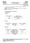
Instruction Sheet
取扱説明書
411 - 78259
19 JAN 2007
Rev. A
Mechatrolink Ⅱ Connector Kit (メカトロリンクⅡ コネクタ キット)
1. はじめに
この取扱説明書は メカトロリンクⅡ コネクタ キッ
トの組立手順、取扱方法を説明するものです。作業の
前に必ずお読みください。
1. Introduction
This manual describes the assembly procedure and
handling of the Mechatrolink Ⅱ Connector Kit.
Read this manual thoroughly before assemble/use
the connector.
2. 適用製品
2. Applicable Products
Part No.(型番)
1827525-1
Descriptions (名称)
Mechatrolink Ⅱ Connector Kit (メカトロリンクⅡ コネクタ キット)
3. 適用ケーブル
取付適用規格も参照してください。
3. Applicable Cable
Refer Application Specification for details.
大電㈱製(HRZFV-SB AWB25×2 心)
DAIDEN Co. Ltd. (HRZFV-SB AWB25×2C)
4. 関連規格
114-5404 :取付適用規格
411-78251 :取扱説明書(SHELL 用ダイスキット)
4. Related Documents
114-5404 : Application Specification
411-78251:Instruction Sheet(Dies Kit for Shell)
5. 組立手順
下記の手順で組み立ててください。
5. Assembly Procedure
Assemble the cable in following procedure:
1) ケーブルシースと心線を Fig.1 に示す寸法に従っ
て、被服剥きを行います。その際、心線に傷をつけな
い様に注意して下さい。もし、傷ついたり、一部が切
断した場合はやり直して下さい。尚、被服剥き後、編
組シールド(ドレンワイヤー含む)をシースの外側に
折り返し、介在と押さえテープは除去します。
1) Strip the cable jacket and insulation of the wires
in accordance with Fig. 1. At this time do not cut or
damage the wires/cable. Cut cable end and retry if
the cable or wires are cut off or damaged. After
strip the cable jacket and insulation of the wires,
turn braid shield (included drain wire) outside of
jacket and remove filler and binder tape.
タイコ エレクトロニクス アンプ株式会社 (〒213-8535 川崎市高津区久本 3-5-8)
1 of
Tyco Electronics AMP K.K. (3-5-8 Hisamoto Takatsu-ku Kawasaki, 213-8535)
この文書の改版の確認は本社、支店へお問い合わせください。 This document is subject to change. Call local AMP for the latest revision.
© Copyright 2003 by Tyco Electronics AMP K.K. All rights reserved.
* : 商標 Trademark
6
Instruction Sheet
411 - 78259
2) 取付適用規格(114-5404)を参照し、導体をサブ
プラグアッセンブリ(インダクタ付)へ半田付け(黒
線心→Pos.2 , 赤線心→Pos.3)します。この時、コネ
クタキット構成部品及びケーブルに傷をつけない様
に注意して下さい。もし、製品機能を損なう傷等がこ
れらの部品についた場合は、新しい部品に交換してや
り直してください。半田付け後、取付適用規格に従っ
て半田付け状態を検査して下さい。
2) Refer to the Application Specification, solder
conductor with sub plug assy (with inductors).
(Black→Pos.2 , Red→Pos.3) At this time, do not
damage component parts of connector kit and
cable. Exchange for new parts, and do over again if
they are damaged that product function is ruined.
After soldering, inspect soldering according to the
Application Specification.
3) キャップハウジングをサブプラグアッセンブリ
(インダクタ付)へ装着します。この時、装着する方
向に注意して下さい。(突起形状側がサブプラグアッ
センブリの極数表示側) また、コネクタキット構成
部品及びケーブルに傷をつけない様に注意して下さ
い。もし、製品機能を損なう傷等がこれらの部品につ
いた場合は、新しい部品に交換してやり直してくださ
い。取付後、両サイドのロック 2 箇所がしっかり掛か
かり、正常に取付けられている事を確認して下さい。
3) Install cap housing in sub plug assy (with
inductors). At this time, note the installed
direction. (Turn the projecting shape in the
direction of the position number display.) And do
not damage component parts of connector kit and
cable. Exchange for new parts, and do over again if
they are damaged that product function is ruined.
After cap housing is installed, Confirm the thing
that the lock of both sides is normally installed.
Rev. A
2 of 6
Instruction Sheet
411 - 78259
4) 向きを確認し、半田付け済みのサブプラグアッセ
ンブリをフロントシェルに挿入します。この時、コネ
クタキット構成部品及びケーブルに傷をつけない様
に注意して下さい。もし、製品機能を損なう傷等がこ
れらの部品についた場合は、新しい部品に交換してや
り直してください。
4) After confirming the direction, insert soldered
sub plug assy in the front shell. At this time, do not
damage component parts of connector kit and
cable. Exchange for new parts, and do over again if
they are damaged that product function is ruined.
5) フロントシェルに半田付け済みのサブプラグアッ
センブリがしっかりと奥まで挿入されている事及び
編組シールド(ドレンワイヤー含む)がケーブルシー
スの外側にきれいに折り返されている事を確認し、バ
ックシェルをフロントシェルに取付けます(取付時に
カチッという感触があります)。この時、コネクタキ
ット構成部品及びケーブルに傷をつけない様に注意
して下さい。もし、製品機能を損なう傷等がこれらの
部品についた場合は、新しい部品に交換してやり直し
てください。取付後、両サイドのロック 4 箇所がしっ
かり掛かかり、正常に取付けられている事を確認して
下さい。
5) Confirm soldered sub plug assy has been firmly
inserted in front shell. Confirm braid shield
(included drain wire) are firmly turned outside of
jacket. After these are confirmed, Install back shell
in front shell. (Lock feeling and sound can be
confirmed when the back shell is fully/correctly
installed.) At this time, do not damage component
parts of connector kit and cable. Exchange for new
parts, and do over again if they are damaged that
product function is ruined. After back shell was
installed in front shell, confirm whether for the
lock of both sides (four places) to hang firmly or to
reach and to be installed normally.
Rev. A
3 of 6
Instruction Sheet
411 - 78259
6) ケーブルシースの端(編組シールド折返し部)が
シェルバレル部根元よりコネクタ側の位置にあり、編
組シールド(ドレンワイヤー含む)が均一にケーブル
シースとシェルバレル部の間にあることを確認した
後、取付適用規格(114-5404)を参照し専用ダイスキ
ット(1891771-1)を使用して圧着して下さい。
(ダイ
スキットの取り扱いに関する詳細は、取扱説明書
(411-78251)を参照して下さい。
) この時、コネク
タキット構成部品及びケーブルに傷をつけない様に
注意して下さい。もし、製品機能を損なう傷等がこれ
らの部品についた場合は、新しい部品に交換してやり
直してください。圧着後、取付適用規格(114-5404)
に従って圧着状態を検査して下さい。
6) Confirm whether the edge of cable jacket (Part
where braid shield is turned) is on the connector
side from the root of barrel, and braid shield
(included drain wire) is even between jacket and
barrel of shells. After these are confirmed, Refer to
the Application Specification (114-5404), crimp the
shells to the jacket by using Dies Kit for Shell.
(Refer to the handling description (411-78251) for
the details about the handling of Dies Kit.) At this
time, do not damage component parts of connector
kit and cable. Exchange for new parts, and do over
again if they are damaged that product function is
ruined. After crimping, check the workmanship in
accordance with the application specification
(114-5404).
7) シェルバレル端部よりはみ出して余った編組シー
ルド(ドレンワイヤー含む)をFig.7示す寸法に従っ
て整えます。この時、コネクタキット構成部品及びケ
ーブルに傷をつけない様に注意して下さい。もし、製
品機能を損なう傷等がこれらの部品についた場合は、
新しい部品に交換してやり直してください。
7) Straighten projecting braid shield (included
drain wire) from the edge of barrel. At that time,
Refer to Fig.7. At this time, do not damage
component parts of connector kit and cable.
Exchange for new parts, and do over again if they
are damaged that product function is ruined.
Rev. A
4 of 6
Instruction Sheet
411 - 78259
8) シェルをカバーハウジングへ収めます。この時、
コネクタキット構成部品及びケーブルに傷をつけな
い様に注意して下さい。もし、製品機能を損なう傷等
がこれらの部品についた場合は、新しい部品に交換し
てやり直してください。
8) Put the shell in the cover hsg. At this time, do
not damage component parts of connector kit and
cable. Exchange for new parts, and do over again if
they are damaged that product function is ruined.
9) ロックスプリング(2セット)がしっかりとカバー
ハウジングに収納されていることを確認し、もう一方
のカバーハウジングを取付けます。この時、コネクタ
キット構成部品及びケーブルに傷をつけない様に注
意して下さい。もし、製品機能を損なう傷等がこれら
の部品についた場合は、新しい部品に交換してやり直
してください。取付後、両サイドのロック4箇所がし
っかり掛かかり、正常に取付けられている事を確認し
て下さい。また、ロック開閉動作が問題なく行える事
を確認して下さい。
9) Confirm the lock spring (two sets) are firmly
stored in the cover hsg. And, install other cover
hsg. At this time, do not damage component parts
of connector kit and cable. Exchange for new parts,
and do over again if they are damaged that product
function is ruined. After back shell was installed in
front shell, confirm whether for the lock of both
sides (four places) to hang firmly or to reach and to
be installed normally. Moreover, confirm whether
the opening and shutting operation of the lock can
be normally done.
Rev. A
5 of 6
Instruction Sheet
411 - 78259
6. 改定記録
6. Revision Record
改訂
LTR
A
Rev. A
改訂記録
REVISION RECORD
RELEASED
作成
DR
K.Riku
検閲
CHK
I.Hasegawa
承認
APVD
I.Hasegawa
年月日
DATE
19JAN2007
6 of 6