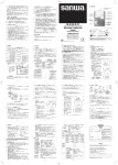
1
【1】Read First: Safety Information
We thank you for your purchasing our product, the battery-driven
insulation resistance tester.
This is a DC resistance tester developed under the principle to provide
new and unique design and function for the measurement of insulation
resistance of each kind of electric equipments. Since this tester
generates high voltage, we recommend that you read this instruction
manual thoroughly,
y and treat the tester correctly and safely.
The symbols used on this tester and in this instruction manual denote
the following meanings:
Be careful as the high voltage is impressed.
Be careful because there is a possibility of bodily injury or the
destruction of equipment.
WARNING
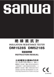
PDM1529S PDM5219S
INSULATION
A
RESISTANCE
T
TESTER
INSTRUCTION MANUAL
Dempa Bldg., Sotokanda 2-Chome
Chiyoda-Ku, To
T kyo, Japan
【5】Description of Functions
・Function control knob and MΩ(insulation resistance) measuring switch
by operating these two switches, the functions and ranges can be
set as shown below.
Position of Function Control Knob
MΩ Measuring Switch (*)
1000 V/2000 MΩ
500 V/100 MΩ
AC 600 V
250 V/100 MΩ
125 V/100 MΩ
1000 V/2000 MΩ
500 V/100 MΩ
AC 600 V
250 V/100 MΩ
125 V/100 MΩ
DC 60 V・BATTERY CHECK
DC 60 V・BATTERY CHECK
Set Range (Function)
PDM1529S
V C range
OFF 600 VA
To ensure that the meter is used safely,
T
y follow all safety and operating
instructions.
11. Never use tester for high power or high voltage circuit.
12. Pay special attention
t
when measuring the voltage of AC 33 Vrms
(46.7 V Peak) or DC 70 V or more to avoid injury.
13. Disconnect power source of the measured circuit before
measuring insulation resistance.
14. High voltage is generated while measuring insulation resistance.
Be cautions of electric shock.
15. After measuring insulation to avoid electric shock. Be sure to
discharge the high voltage charged.
16. Never apply an input signal exceeding the maximum rating input
value.
17
7. Never use tester for measuring the line connected with
equipment (i.e. motors) that generates induced or surge voltage
since it may exceed the maximum allowable voltage.
18. Never use tester if the tester or test leads are damaged or broken.
19. Never use uncased tester.
10. Always keep your fingers behind the finger guards on the probe
when making measurements.
11. Be sure to disconnect the test pin from the circuit when changing
the function.
12. Never use tester with wet hands or in a damp environment.
13. Never use test leads other than the exclusive test leads.
14. Never open tester case except when replacing batteries.
Do not attempt
t
any alterations of original specifications.
15. To
T ensure safety and maintain accuracy, calibrate and check the
tester at least once a year.
16. Indoor use.
CAUTION
Remove components such as semi-conductors and apparatuses from
the circuit of measuring object to avoid damages when withstand
of the object is unknown or lower than rated measuring voltage of a
resistance insulation tester, especially in case of the objects you
measure connected with PCs or computers.
*The MΩ measuring switch is turned on by the following operation.
① ON only when the right end of the lever is pressed with a finger.
(OFF when the finger is released)
② Continuously ON when the left end of the lever is raised. (OFF
when it is laid down)
Function control knob
【4】Storage
CAUTION
・The panel and the case are not resistant to heat. Do not place the
instrument near heat-generating devices (such as a soldering iron).
・Do not store the instrument in a place where it may be subjected
to vibration or from where it may fall.
・For storing the instrument, avoid hot, cold or humid piaces or places
under direct sunlight or where condensation is anticipated.
・ This tester complies with the revision of JIS C1302-2002 insulation
resistance meters.
− 3 −
6.3 Measurement of MΩ (Insulation Resistance)
WARNING
1. Never apply a voltage to the measuring terminal when the tester
is in the MΩ measuring range.
2. Prior to measurement, disconnect the measuring object (circuit)
from the power supply.
3. Prior to measurement, make sure no voltage is applied to the
circuit to measure by the AC 600 V range.
4. During measurement, a high voltage is generated. Do not touch
the test pin, clip and measuring object.
5. The tester and measured circuit have been charged by high voltage
immediately aft
f er the measurement. Be careful not to get electric
shock.
6. There is a possibility of an accident of electric shock. After the
measurement, be sure to discharge the high voltage charged in
the measuring object. (See 6.4 Discharge Function)
Check start.
Replace
battery.
See 7.4
Battery
Replacement.
Check built-in battery.
Check appearance and pointer 0 position.
Main unit and
test lead damaged
in appearance?
Body securing band
d
Turn function control knob
to DC 60 V/BATTERY CHECK.
Stop using.
Repair it.
No damaged
Body comp
partment
Pointer at 0 position
when main unit is placed
horizontally?
To carr y while held
T
by hand
No
Yes
Place main unit
horizontally,
adjust pointer 0
position adjuster
with screwdriver
to bring pointer
to 0 position.
Turn on MΩ
switch.
Pointer is on left of battery
check scale(BATT)?
Yes
No
Turn function control knob
and MΩ switch to OFF.
A
Check measuring lead wiring breakage.
*
Release push switch and replace test
lead with new one and re-check.
If replacement does not work, repair
Connect lead with clip to EARTH terminal
and lead with test pin to LINE terminal.
CAUTION
No
Join by hookk
Clamp test pin with clip (to short).
1. When the measuring object is grounded (earth), a normal practice
is to connect the lead with clip (EARTH) to ground (earth) and the
lead with test pin (LINE) to the circuit. (When this connection is
used, a measurement value becomes smaller than a value
obtained by the reverse connection.)
2. To
T prevent a measuring error, keep the test lead connected to
the LINE side out of contact with the measuring object and ground
(earth).
3. The insulation resistance varies largely depending on temperature
and humidity. It is also influenced by a voltage to apply (measuring
voltage).
Normally as temperature, humidity and voltage increase, the
insulation resistance decreases.
Pointer is at almost 0 MΩ
position of insulation resistance
scale ?
Join by hook
Turn function control knob to
AC 600 V・250 V/500 MΩ.
Raise left end
Press right end
Yes
Turn MΩ measuring switch and
function control knob to OFF.
Turn on MΩ measuring switch.
【6】Measuring Method
Normal. Proceed to measurement.
6.1 Start-up Check
WARNING
・Meter zero position adjustment
If the meter pointer is not on the ∞ graduation line of the MΩ scale
when the function control knob is at OFF
F, adjust the zero position
with a screwdriver.
− 4 −
REFERENCE
2)
Measuring object
Measurement of insulation resistance (MΩ) of electric equipment
and circuits.
Rated measuring voltage
Model
PDM1529S
PDM5219S
6.2 How to Check Bult-in Battery (BATTE
A
RY CHECK)
Prior to MΩ (insulation resistance) measurement, be sure to check the
built-in battery. A consumed batte
t ry will cause not only measurement
errors but danger due to erroneous measurement.
For checking methods, refer to 6.1 Start-up Check.
Do not check the built-in battery for more than 5 seconds.
− 6 −
− 5 −
1. The rated measuring current of this tester is 1 mA. (1 mA to 1.2
mA when the resistance of a value below the rated measuring
voltage/1 mA and within 1st effective measurement scale is
measured.)
2. The no-load voltage is within 1.3 times the rated measuring
voltage.
3. While measuring there may be an oscillator noise from the meter,
r
but this is not a malfunction.
1)
1. Do not use a damaged tester or test lead.
2. Make sure test lead wiring is not broken.
3. When testing the continuity of a test lead, the measuring terminals
are under a high voltage. Be careful of electric shock.
4. To
T prevent electric shock and battery consumption, be sure to
turn the MΩmeasuring switch and function control knob to OFF
after measurement.
⑤ Bring the test pin of the lead with test pin in contact with the
other side of the measuring object.
CAUTION : If the meter deflects in this state, the measuring
object is charged. Be sure to remove the voltage
prior to measurement.
⑥ T
Turn on the MΩ measuring switch.
(See [5] Description of Functions)
⑦ Read the indicated value. Use the appropriate scale according to
the position of the function control knob (set range). (See following fig)
⑧ Turn off the MΩ measuring
switch.
⑨ Discharge the high voltage
charged in the measuring
object. See 6.4 Discharge
Function.
Rated measuring voltage
250 V/500 V/1000 V
125 V/250 V/500 V
6.4 Discharge Function
1) Reason of a need to discharge
For safety, high voltage remaining in capacitive measuring objects
such as capacitors and electric wire must be discharged to prevent
accidents.
2) Discharging method
This procedure follows the step ⑧ of 6.3-4)
① When the MΩ measurement has been completed, turn off only
the MΩ measuring switch with the test pin and the clip connected
to the measuring object.
② Then the pointer deflects to the right and its deflection becomes
smaller as time passes (indicating the charged charge is being
discharged).
③ When the pointer stops at zero (∞ of the MΩ scale) and discharge
has been completed, conduct the steps ⑩ and ⑪ of 6.3-4)
6.5 Measurement of ACV (AC voltage) (Measuring range is the AC 600 V range only)
Selection of a measuring range
When measuring insulation resistance, select a range of the voltage
that is close to the voltage used by the circuit to measure, unless
otherwise specified.
For example, when measuring insulation resistance of 100 V home
appliances and indoor wiring, select the 125 V rated measuring
voltage range and when measuring 200 V power circuits, select
the 250 V rated measuring voltage range.
4) Measuring method
① Power off the measuring object.
② Connect the lead with clip (black) to the earth side measuring
ternimal (EARTH) and the lead with test pin (red) to the line side
measuring terminal (LINE).
③ Turn
T
the function control knob to a desired rated measuring
voltage range.
④ Connect the clip of the lead with clip to the measuring object.
Normally, the earth side measuring terminal should be on the
earth line side.
1. Do not apply a voltage exceeding the maximum rated voltage of
600 VA
V C.
2. During measurement, do not operate the function control knob.
3. Do not measure a voltage with the MΩ measuring switch being
pressed or raised.
4. When the circuit to measure has a breaker, measure the voltage
on the secondary side (load side).
5. To
T prevent electric shock, do not touch the metal part of the pin
plug and clip.
⑩ First, disconnect the test pin of the lead with test pin from the
measuring object. Then remove the clip of the lead with clip.
⑪ Be sure to turn the function control knob to the position of OFF
F.
1000 V
Scale of 2000 MΩ range
(
)
1)
500 V,250 V
Scale of 100 MΩ
range
(
)
〔Example. PDM1529S〕
Measuring object
Sinusoidal AC voltages (ACV) such as lighting line voltages can be
measured.
2) Measuring method
① Connect the lead with clip(black) to the earth side measuring
terminal and the lead with test pin (red) to the line side measuring
terminal.
(PDM5219S is a scale common to all ranges.)
− 9 −
③ Connect the lead with clip (black) to the negative (−) side of the
measuring object (circuit) and the lead with test pin (red) to the
positive (+) side.
④ Read the indicated value on the DCV scale.
⑤ Disconnect the lead with test pin and the lead with clip in this
order from the measuring object.
⑥ T
Turn the function control knob to the position of OFF.
【7】Batt
t ery Replacement
Screw
ws
① Remove two batter y lid
Battery lid
securing screws.
② Replace the consumed
Sn
nap terminal
batte
t ry that is connected to
the snap terminal with a new
one.
③ Set the batte
t ry in the original
6LR61
1 Battery
place and secure the batte
t ry
(6LF22
2)
lid with screws.
Be sure to turn the function control knob to the position of
OFF prior to replacing the battery.
㸝9㸞
Be sure to use the alkaline battery 6LR61 (6LF22) x1(9 V)
【8】Aft
f er-Sales
r
Service
8.1 Warranty and Provision
Sanwa offers comprehensive warranty services to its end-users and to
its product resellers. Under Sanwa's general warranty policy, each
instrument is warranted to be free from defects in workmanship or
material under normal use for the period of one (1) year from the date
of purchase.
This warranty policy is valid within the country of purchase only, and
applied only to the product purchased from Sanwa authorized agent or
distributor.
Sanwa reserves the right to inspect all warranty claims to determine
the extent to which the warranty policy shall apply. This warranty shall
not apply to test leads, disposables batteries, or any product or parts,
which have been subject to one of the following causes:
1. A failure due to improper handling or use that deviates from the
instruction manual.
12 −
− 7 −
CAUTION
AC voltages of waveforms other
than sinusoidal waveforms and
frequencies other than 50 to 60
Hz will cause an indication error.
② T
Turn the function control knob to
AC 600 V.
V
③ Connect the lead with clip to the
earth side of the circuit to
measure and the lead with test
pin to the charging side (line side).
④ Read the indicated value on the ACV scale.
⑤ Disconnect the lead with test pin and the lead with clip in this
order from the measuring object.
⑥ T
Turn the function control knob to the position of OFF.
6.6 Measurement of DCV (DC voltage) (Measuring range is the D
DV 60 V range only)
WARNING
3)
− 8 −
Line side measuring
terminal (LINE)
Earth side measuring
terminal (EARTH)
2.2 Features
This tester has the minimum number of scale graduations and
employs a three-range system for easy viewing and readability.
Damaged
*
Battery check
scale
MΩ
(insulation
resistance)
measuring
switch
2.1 Applications
・DC insulation resistance tester to measure the insulation resistance
of electric lines and electric equipment.
Before starting measurement, check the“appearance”
“pointer
,
0
position”
(*),“built-in batte
t ry”and“measuring lead”in this order. (*The
pointer 0 position is the 0 position of the DC 60 V scale or ∞ position of
the MΩ scales.)
Test
T
e lead
co
ompartm
ment
DCV scale
Maximum overload
protection input
AC 720 V
AC 600 V
HowTo
T Use Carrying Case
During measurement, set the case as illustrated and hang it from
the neck.
PDM1529S
Pointer
0 position
adjuster
【2】Applications and Features
PDM5219S
1000 V/2000 MΩ range
500 V/100 MΩ range
ON
250 V/100 MΩ range
PDM5219S
125 V/100 MΩ range
DC 60 V range
OFF
BATTE
A RY CHECK range
ON
Maximu rating
input value
AC 600 V
DC 60 V
− 2 −
To hang from the neck
T
during measurement
MΩ scale
(insulation resistance)
ACV scale
Pointer
Maximum Overload Protection Input
Function
(Range)
ACV (600)
DCV (60)
− 1 −
・Lid turns in
direction at pivot the A.
・Lay it along the bottom
t
of the box and secure it
by hooks marked by*
【3】Front View and Name of Each Part
r
2. A failure due to inadequate repair or modification by people other than
Sanwa service personnel.
3. A failure due to causes not attribu
t
table to this product such as fire,
flood and other natural disaster.
4. Non-operation due to a discharged batte
t ry.
5. A failure or damage due to transportation, relocation or dropping afte
f r
the purchase.
8.2 Repair
Customers are asked to provide the following information when
requesting services:
1. Customer name, address, and contact information
2. Description of problem
3. Description of product configuration
4. Model Number
5. Product Serial Number
6. Proof of Date-of-Purchase
7. Where you purchased the product
1) Prior to requesting repair, please check the following:
Capacity of the built-in batte
t ry,
y polarity of installation and discontinuity
of the test leads.
2) Repair during the warranty period:
The failed meter will be repaired in accordance with the conditions
stipulated in 8-1 Warranty and Provision.
3) Repair after
f the warranty period has expired:
In some cases, repair and transportation cost may become higher
than the price of the product. Please contact Sanwa authorized agent
/ service provider in advance.
The minimum retention period of service functional parts is 6 years
after
f the discontinuation of manufacture. This retention period is the
repair warranty period. Please note, however,
r if such functional parts
become unavailable for reasons of discontinuation of manufacture,
etc., the retention period may become shorter accordingly.
4) Precautions when sending the product to be repaired
T ensure the safety of the product during transportation, place the
To
product in a box that is larger than the product 5 times or more in
volume and fill cushion materials fully and then clearly mark “Repair
Product Enclosed” on the box surface. The cost of sending and
returning the product shall be borne by the customer.
8.3 SANWA
W web site
http://www.sanwa-meter.co.jp
E-mail: [email protected]
− 13 −
WARNING
1. Do not apply a voltage exceeding the maximum rated voltage of
60 VDC.
2. Keep in mind the warnings of 6.5 described earlier.
1)
Measuring object
DC voltages of batteries,
t
etc. can be
measured. Also, the tester can be
used to check the presence of DC
voltage prior to MΩ measurement.
2) Measuring method
① Connect the lead with clip (black)
to the earth side measuring
terminal
and the lead with test pin (red) to
the line side measuring terminal.
② Turn
T
the function control knob to
DC 60 V/BATTE
A
RY CHECK.
− 10 −
− 11 −
Accessorie
【9】Specifications
9.1 General Specifications
AC rectifying method : Half-wave rectification
(Mean value indication rms value converted)
Meter specification : Inner-pole
r
type taut-band system, 48μA
Batte
t ry consumption : Checked by BATTE
A
RY CHECK range.
Allowable temperature/humidity range
: 23±5 ℃, 75 % RH max., no condensation.
Service temperature/humidity : 0∼43 ℃, 80 % RH max., no condensation.
Storage temperature/humidity : -10∼50 ℃, 70 % RH max., no condensation.
Service ambient condition : Altitude 2000 m max., environmental pollution Ⅱ.
Built-in batte
t ry
: Layer built type alkaline batte
t ry 6LR61(6LF22) x1(9 V)
*Factory-preinstalled built-in battery
A battery for monitoring is preinstalled before shipping, therefore it
may run down sooner than the batte
t ry life specified in the instruction
manual.
The “batte
t ry for monitoring” is a batte
t ry to inspect the functions and
specifications of the product.
Max. power consumption : Approx 2.6 W (at 1000 V/2000 MΩ range)
Batte
t ry life
: When the lower limit measurement resistance
value that can maintain the rated output
voltage is measured and if one cycle for the
measurement is defined as ON for 5 seconds
and OFF for 25 seconds, the batte
t ry life is 500
cycles.
Applicable standard : JIS C 1302-2002 Insulation resistance testers.
Safety
: EN61010-1 Over Vol
V tage Category Ⅲ (CAT
AT. Ⅲ),
600 V Pollution Degree 2
EMC
: EN61326
Degree of IP
: IP20
Withstand voltage
: 3.7 kV AC (one minute), between measuring
terminal and rear case.
Year of manufacture : The first two digits of the serial number on
the bottom of this product indicate the last
two digits of the year.
Size and mass
: 144 (H ) x 99 (W ) x 43 (D) mm, approx. 310 g
− 14 −
:T
Test lead TL-508Sa,
L
1 set
Carrying case C-08S, 1 piece
Instruction manual, 1 copy
9.2 Measurement Range and Accuracy
7.1 Accuracyassurance
: 23
5
75 RH max.
No condensation
7.1 Attitude
: Horizontal ( 5 )
Model
PDM1529S
M
Insulation
Resistannce
(
)
Rated measuring Vol
V tage
Maximum value
PDM5219S
Large
g numeral :
1st effective measurement scale
Small numeral :
2nd effective measurement scale
1000 V
2000 M
0.5
500 V
100 M
250 V
100 M
Rated measuring Vol
V tage
Maximum value
2 1000
2000 M
500 V
100 M
0.02
0.1 50
100 M
0.02
0.1 50
100 M
250 V
100 M
0.02
0.1 50
100 M
0.02
0.1 50
100 M
125 V
100 M
0.02
0.1 50
100 M
ACV
0~600 V
DCV
0~60 V
Accuracy
Large
g numeral :
1st effective measurement scale
Small numeral :
2nd effective measurement scale
M range
1st effective : measurement range : 5 % of reading
2nd effective : measurement range : 10 % of reading
0,
scale
: 0.7 % of scale length
No load voltage
: 30
0 % of rated measuring voltage
Rated measuring current : 1~1.2 mA
Short circuit current : max 3 mA
ACV range (50/60 Hz sine wave) : 5 % of full scale
DCV range
:
− 15 −
5 % of full scale