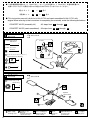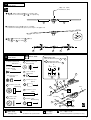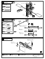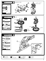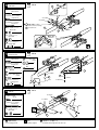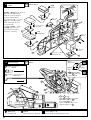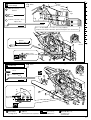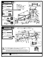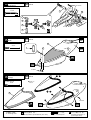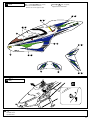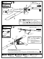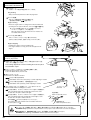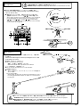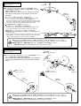
1
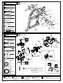
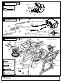
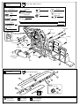
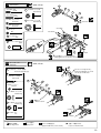
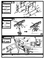
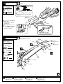
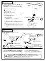
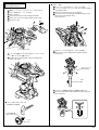
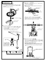
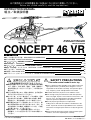
̪ߏ↪೨ߦߎߩ⺑ᦠࠍ⦟ߊ߅⺒ߺߦߥࠅలಽߦℂ⸃ߒߡߊߛߐޕ $GHQTGWUGRNGCUGECTGHWNN[TGCFVJGGZRNCPCVKQPU INSTRUCTION MANUAL R ⚵┙㧛ขᛒ⺑ᦠ THE FINEST RADIO CONTROL MODELS RADIO CONTROLLED 46 ENGINE POWERED HELICOPTER CONCEPT 46 VR ⋡˴ᰴ˴INDEX ٨ࠠ࠶࠻ߩઁߦߘࠈ߃ࠆ‛˴REQUIRED FOR OPERATION ٨ࡊࡠࡐߩḰ˴RADIO PREPARATION ٨˴˴˴˴˴˴˴˴BEFORE YOU BEGIN ٨ᧄߩ⚵┙ߡ˴ASSEMBLY ٨˴˴˴˴˴˴˴OPERATING YOUR MODEL SAFELY ٨⺞ᢛ㘧ⴕ✵⠌ࡔࡦ࠹࠽ࡦࠬ˴SETTINGSFLIGHT LESSONSMAINTENANCE ٨ࡄ࠷ࠬ࠻˴PARTS LIST ٨ಽ⸃࿑˴EXPLODED VIEW ٨ࠬࡍࠕࡄ࠷ࠝࡊ࡚ࠪࡦࡄ࠷ࠬ࠻˴SPARE & OPTIONAL PARTS 2 3 4~5 6 ~ 24 25 26 ~ 35 36 37 ~ 41 42 ~ 44 SAFETY PRECAUTIONS ˴ߎߩή✢ᠲ❑ᮨဳߪౕߢߪࠅ߹ߖࠎ㧍 This radio control model is not a toy. ٨㜞ㅦߢ࿁ォߔࠆࡠ࠲߇ઃߚෂ㒾ᕈߩࠆᯏ᪾ ˴ߢߔޔߡ┙⚵ޕ㘧ⴕ ႐ᚲޔ㔚ᵄޔὐᬌޔᢛߪߏ ⥄り߇⽿છࠍ߽ߞߡⴕߞߡߊߛߐߩߥߪࠇߎޕ ˴⽿છߢߔޕ ٨ዊߐㇱຠ߇ᄙߩߢߡ┙⚵ޔᬺߪޔᔅߕᐜఽߩ ˴ᚻ߇ߣߤ߆ߥᚲߢⴕߞߡߊߛߐޕ ٨ࡈࠗ࠻೨࠻ࠗࡈޔᓟߪᔅߕޔߺ✭ߩࠬࡆޔฦㇱ ˴ຠߩഠൻߥߤࠍὐᬌߒ⇣ޔᏱ߇ࠇ߫឵ୃℂ ˴⺞ᢛࠍⴕޔోࠍ⏕ߒߡ߆ࠄߏ↪ߊߛߐޕ ٨⚐ᱜㇱຠએᄖߩࡄ࠷ࠍ↪ߒߥߢߊߛߐޔ ˴߿ਇ⺞ߩේ࿃ߦߥࠆ߅ߘࠇ߇ࠅ߹ߔ␠ޔߚ߹ޕ ˴ᄖຠࠍ↪ߒߡߩޔ⎕៊╬ߦߟߡߪ৻ޔಾ⽿ ˴છࠍ⽶߹ߖࠎੌߏޔᛚߊߛߐޕ ٨⚵┙ߡᓟߦ৻߁߽ޔᐲ⺑ᦠࠍ⋥ߒߡਅߐޕ ˴⺑ᦠߪߦ߁ࠃࠆࠇࠄ߽ߢߟޔᄢಾߦ▤ߒߡ ˴ߊߛߐޕ ٨This is a kind of machine including a rotor which rotates with high speed and has a possibility to be dangerous. You are responsible for this model's assembly, safe operation (place to fly, frequency) check and adjustment of the model. ٨Assemble this kit only in places out of children's reach! ٨Take enough safety precaution before and after operation. After every flight, inspect screws and nuts for looseness, and parts for wear. Any damaged parts should be immediately replaced, repaired or adjusted for safe operation. ٨Use only Kyosho genuine parts for replacement. Failing to do so will result in accidents or malfunction of the model. Kyosho do not take responsibilities for the accidents and crashes if using the parts which are not Kyosho genuine ones. ٨Always keep this instruction manual ready at hand for quick reference, even after completing the assembly. ̪ຠᡷ⦟ߩߚ੍ޔ๔ߥߊ᭽ࠍᄌᦝߔࠆ႐ว߇ࠅ߹ߔ ޕSPECIFICATIONS ARE SUBJECT TO CHANGE WITHOUT NOTICE. © 1997 KYOSHO㧛ήᢿォタⶄ No. 21722㧔ࠠ࠶࠻㧕 No. 21721㧔ࠛࡦࠫࡦઃඨቢᚑࠠ࠶࠻㧕 No.21721 / No.21722 ࠦࡦࡊ࠻84 CONCEPT 46 VR R ⿷⺑ᦠ SUPPLEMENTARY INSTRUCTION SHEET THE FINEST RADIO CONTROL MODELS ขᛒ⺑ᦠߦᄌᦝ߇ࠅ߹ߔࠆߡ┙⚵ޕ೨ߦᔅߕߎߩ⿷⺑ᦠࠍ߅⺒ߺߊߛߐޕ Please use these supplementary instructions in conjunction with the manual included in your kit. ࡍࠫ Page 11 15 ࠛࡦࠫࡦ Engine VR-6, VR-B 58 4mm ࠞ࠙ࡦ࠲ࠡࡗߩ⚵┙ߡࠍ ߒߡߊߛߐޕ Assemble the counter gear. 57 56 18 4mm 55 312mm 320mm 312mm 469 314mm 175 312mm 314mm 3mm ࠞ࠙ࡦ࠲ࠡࡗߩࡃ࠶ࠢ࠶ࠪࡘ߇߈ߟ႐วߪޔ 3X14mmࠠࡖ࠶ࡊࡆࠬࠍߒࠆᤨߦోࡦࠫࡦࠛޔ ࠍਅߍߥ߇ࠄࠠࡖ࠶ࡊࡆࠬ4ᧄࠍߒߡ⺞ᢛߒߡߊߛߐޕ If the backlash is too close, tighten the four pcs. of 3X14mm cap screws as holding the engine downward. ࡍࠫ Page 19 32 ࠹࡞ࡄࠗࡊขઃߌ Tail Pipe 318mm ࠠࡖ࠶ࡊࡆࠬ ˴˴˴˴ Cap Screw 3X18mmࠠࡖ࠶ࡊࡆࠬ㧔ᧄ㧕ߣޔ 3mm࠽ࠗࡠࡦ࠽࠶࠻㧔㧕߇ㅊ ടߦߥࠅ߹ߔޕ Ensure to tighten 3X18mm cap screws (2 pcs.) and 3mm nylon nut (2 pcs.) . 2 3mm ࠽ࠗࡠࡦ࠽࠶࠻ ˴ Nylon Nut 3mm 2 ࠹࡞ࡉࡓߪޔ࿑ߩ⟎߹ߢ ᔅߕᏅߒㄟޕ Insert the tail boom up to the mark indicated. ⚂60mm approx. 60mm ࿑ߩࠡࡗࠍ࿁ߒߡߺߡ࡞࠹ޔ ࡠ࠲߇㚟േߔࠆ߆⏕ߔࠆޕ Rotate the gear and check if the tail rotor rotates. 3mm ̪ຠᡷ⦟ߩߚ੍ޔ๔ߥߊ᭽ࠍᄌᦝߔࠆ႐ว߇ࠅ߹ߔޕ *SPECIFICATIONS ARE SUBJECT TO CHANGE WITHOUT NOTICE. © 1997 KYOSHO㧛ήᢿォタⶄ ੩ᩣᑼળ␠ 9711 PRINTED IN JAPAN ࠠ࠶࠻ߩઁߦߘࠈ߃ࠆ‛㧔㧝㧕REQUIRED FOR OPERATION (1) 1 عන㧟ੇ㔚ᳰ㧔ㅍାᯏ↪㧕 AA-size Batteries (for transmitter) ࡐࡠࡊ↪ࡋࡦࠫࡦࠛع Radio for engine-powered R/C helicopters ࠛࡦࠫࡦࡋ↪ή✢ᠲ❑ᯏ㧔ࡊࡠࡐ㧕 ߣ㔚ᳰ Radio for engine-powered R/C helicopters, and dry batteries ٨ߎߩࠠ࠶࠻ߦߪࠛࡦࠫࡦࡋ↪㧔ࠨࡏ ࠫࡖࠗࡠ㧕ߩࡊࡠࡐ߇ᔅⷐߢߔޕ ٨ࡊࡠࡐߩขᛒߪߦࡐࡠࡊޔઃዻߩ⺑ᦠ ࠍෳ⠨ߦߒߡߊߛߐޕ AA ٨This kit requires a radio for engine-powered R/C helicopters with 5 servos and 1 gyro. ٨For more information on the radio, refer to its explanations. ᵈᗧ AA ↪ߢ߈ࠆࠨࡏࠨࠗ࠭ SUITABLE SERVOS ⓨ↪㧔ࡋ↪㧕ߩࡊࡠࡐ࠶࠻ࠍᔅߕ ↪ߒߡߊߛߐޕ㧔ⓨ↪એᄖ↪ᱛ㧕 CAUTION: Only use a radio for R/C helicopters! (Any other radio is prohibited!) 33 ~ 36mm 39 ~ 41mm 19 ~ 20mm ᧄ⺑ᦠߩࡊࡠࡐࠗࠬ࠻ߪ(ޔWVCDCขᛒ⺑ᦠࠃࠅォタߒ߹ߒߚޕ The illustrations showing the radio were taken from the Futaba radio explanations. 2 ࠛࡦࠫࡦ 3 Engine ٨ඨቢᚑࠠ࠶࠻ࠍ߅⾈᳞ߩᣇߪࠫࡦࠛޔ ࡦߪขઃߌᷣߢߔߪࡈࡑޕขઃߌߡߊ ߛߐޕ ٨With semi-assembled kits, the engine comes pre-installed. Install the muffler. ࡦࠫࡦࠛ↪ࡋع .46 engine for helicopters ࠣࡊع Glow Plug ࠣࡠΆᢱޔΆᢱࡐࡦࡊ Glow Fuel and Fuel Pump ٨ᮨဳ↪ࠛࡦࠫࡦߪኾ↪ߩࠣࡠΆᢱ߇ᔅⷐ ߢߔ߿ࡦ࠰ࠟޕἮᴤߪ↪ߢ߈߹ߖࠎߩ ߢᵈᗧߒߡߊߛߐࡠࠣޔߚ߹ޕΆᢱߪ ើ⊒ᕈ߇㜞ߊᒁἫߒ߿ߔߩߢขᛒߦߪ లಽᵈᗧߒߡߊߛߐޕ ٨Άᢱߪࡠ࠻࠾ޔಽ㧑એ߇ㆡߒߡ߹ߔޕ ࡠࠣعΆᢱ Glow Fuel ٨Engines for R/C models require glow fuel. 500H Do not use gasoline or kerosene; both gine fuel model en cannot be used! Also, be very care-ful when han-dling glow fuel which is high-ly inflamma-٨No. 6054 K&B500HΆᢱ ble and high-explosive! ٨Fuel should contain at least 10% of nitro. K&B500H Model Engine Fuel عΆᢱࡐࡦࡊ Fuel Pump ࠟ࠰ࡦ߿Ἦᴤߪ ↪ᱛ ⼊๔ 4 WARNING: Gasoline or kerosene cannot be used! ᆎേ↪ౕ Required for engine starting: ࠲ࡅࠣࡊع Plug Heater 5 ࠲࠲ࠬع Starter ٨No. 80701 Άᢱࡐࡦࡊ㧔㔚േ8㧕 Fuel Pump (Electric 12V) ٨No. 80702 Άᢱࡐࡦࡊ㧔ᚻേ㧕 Fuel Pump (Manual) ធ⌕╬ Glues & Lubes ࠢ࠶ࡠࠫࡀع Screw Locking Compound / Screw Cement / Threadlocker ࠬࠣع Grease No. 96506 ࡏ࡞࠺ࡈࠣࠬ Ball Diff Grease Grease ٨ࡠ࠶ࠢ࠲ࠗ࠻ Loctite No. 94402 ਛᒝᐲ Medium Strength ٨No. 1791 ࡉ࠶࠷ࠬ࠲࠲ Blitz Starter ↪࠲࠲ࠬع8ࡃ࠶࠹ 12V Battery ٨No. 71481 ࠪ࡞࠼ࡃ࠶࠹ ˴˴˴˴˴˴Sealed Battery 6 ߐࠄߦ↪ᗧߔࠆߣ⦟߽ߩ 8# Epoxy A Epoxy B ع⍍㑆ធ⌕ Instant Glue Equipment coming in handy عΆᢱࡈࠖ࡞࠲ Fuel Filter ٨No. 96715 ࡢࡦ࠲࠶࠴ࡊࠣࡅ࠲ One-touch Plug Heater 2 No. 94403 㜞ᒝᐲ Hard Strength ࠪࠠࡐࠛعធ⌕ Epoxy Glue ٨No. 96627 ࠢࠗ࠶ࠢ࠲ࠗ࠻ࠫࠚ࡞ࡏࠗ GelBoy˴˴˴˴˴˴˴˴˴˴ ٨No. 1876/No. 39308 Άᢱࡈࠖ࡞࠲ Fuel Filter ࠠ࠶࠻ߩઁߦߘࠈ߃ࠆ‛㧔㧞㧕˴REQUIRED FOR OPERATION (2) 7 ⚵┙ߡߦᔅⷐߥᎿౕ Tools required ࠴ࡦࡍࠝࠫع Needle Nose Pliers ࠠ࠶࠻ߦߞߡࠆᎿౕ TOOLS INCLUDED ࠴ࡦⷺع㧔1.5mm, 2mm, 2.5mm, 3mm㧕 Hex Wrench (1.5mm, 2mm, 2.5mm, 3mm) ᵈᗧ ↪ߔࠆᎿౕߩขᛒߦߪޔలಽᵈᗧߒߡߊߛߐޕ CAUTION: Handle tools carefully! WICHTIG: Gehen Sie vorsichtig mit Werkzeugen um! IMPORTANT: Maniez les outils avec prudence! ع㧗࠼ࠗࡃ㧔ᄢޔਛޔዊ㧕 Phillips Screw Driver (L.M.S) ࡄ࠶࠾ع Wire Cutters ࡈࠗ࠽࠲࠶ࠞع Sharp Hobby Knife ࠠع Awl ࠴ࡦࠣࡊع ˴Plug Wrench ࠬࡍࠪࡖ࡞࠹ࡄࡑ SPECIAL TAPER REAMER No.80311 ਅⓣടᎿ߇ਇⷐߢ⋥ޔធOO㨪OOߩⓣߌ߇ ߢ߈ࠆᎿౕߢߔޕ No need to pre-drill! Drills neat 1mm to 15mm holes directly! ࡊࡠࡐߩḰ˴RADIO PREPARATION ٨ࡊࡠࡐࠍਅߩ㗅⇟ߦߒߚ߇ߞߡ࠶࠻ߒ߹ߔޕ Set up the radio as explained below. 2 12 8 ON 10 OFF 3 5 ًࠬࠗ࠶࠴ Switch 9 1 4 6 ًㅍାᯏ Transmitter 7 11 ON OFF ًࠨࡏ Servo ٨ࡃࠬࠬࠗ࠶࠴ Reverse Switch ࡇ࠶࠴ Pitch ࠛ࡞ࡠࡦ Aileron ࡁࡑ࡞ Normal ࠛࡌ࠲ Elevator ࠬࡠ࠶࠻࡞ Throttle ࡃࠬ Reverse ࠳ Rudder ًฃାᯏ Receiver ًࠫࡖࠗࡠ Gyro ٨ᆎࠆᤨ ٨START 1 නੇ㔚ᳰࠍ࠶࠻ߔࠆޕ㧔ㅍାᯏ㧕 1 Insert AA-size dry batteries. (Transmitter) 2 ࠕࡦ࠹࠽ࠍߩ߫ߔޕ㧔ㅍାᯏ㧕 2 Extend the antenna. (Transmitter) 3 4 ల㔚ߒߚฃାᯏ↪࠾ࠞ࠼ࡃ࠶࠹ࠍߟߥߋޕ 3 Connect the charged Ni-Cd battery. ࠕࡦ࠹࠽ࠍߩ߫ߔޕ㧔ฃାᯏ㧕 4 Extend the antenna. (Receiver) 5 6 7 ࠬࡠ࠶࠻࡞ߩ࠻ࡓࠍਅߍࠆޕ Down the trims. ࠬࠗ࠶࠴ࠍࠇࠆޕ㧔ㅍାᯏ㧕 5 6 7 8 ࠬࠗ࠶࠴ࠍࠇࠆޕ㧔ฃାᯏ㧕 8 Switch on the receiver. 9 ࠬ࠹ࠖ࠶ࠢࠍേ߆ߒߡࠨࡏ߇േߡࠆ߆⏕ޕ 9 Make sure the servos move according to your transmitter inputs. ࠬࡠ࠶࠻࡞એᄖߩ࠻ࡓࠍਛᄩߦ࠶࠻ߔࠆޕ ٨⚳ࠊࠆᤨ 10 ࠬࠗ࠶࠴ࠍಾࠆޕ㧔ฃାᯏ㧕 11 12 Center the trims. Switch on the transmitter. ٨FINISH 10 Switch off the receiver. ࠬࠗ࠶࠴ࠍಾࠆޕ㧔ㅍାᯏ㧕 11 Switch off the transmitter. ࠕࡦ࠹࠽ࠍ❗ࠆޕ㧔ㅍାᯏ㧕 12 Retract the antenna. (Transmitter) 3 ⚵┙ߡ೨ߩᵈᗧ㧔㧝㧕 BEFORE YOU BEGIN (1) 1 ⚵┙ߡࠆ೨ߦ⺑ᦠࠍ⦟ߊ⺒ࠎߢߩߘࠃ߅߅ޔ᭴ㅧࠍℂ⸃ߒߡ߆ࠄ⚵┙ߡߦߞߡߊߛߐޕ 2 ࠠ࠶࠻ߩౝኈࠍ߅⏕߆ߊߛߐ৻ਁޕਇ⦟ޔਇ⿷߇ࠅ߹ߒߚࠄ⾈߅ޔ᳞ߩ⽼ᄁᐫߦߏ⋧⺣ߚߛߊ߆ޔ ᒰ␠⺣⋧࡙ࠩޟቶߏߢ߹ޠㅪ⛊ߊߛߐޕ Read through the manual before you begin, so you will have an overall idea of what to do. Check all parts. If you find any defective or missing parts, contact your local dealer or our Kyosho Distributor. 3 ⺑ᦠߩ߆ߚ How to read the instruction manual: 9 ާ⺑ Example ި ࠹࡞ 6CKN HH-2 2.6 x 10mm ࠠࡖ࠶ࡊࡆࠬ Cap Screw 2 3 x 3mm ࠶࠻ࡆࠬ Set Screw 1 2.6mm ࠽ࠗࡠࡦ࠽࠶࠻ Nylon Nut ⺑ᦠౝߢߪᄙߊߩࡑࠢ߇↪ ߐࠇߡ߹ߔߦࠢࡑޕᵈᗧߒߡ ⚵┙ߡࠍㅴߡߊߛߐޕ This instruction manual uses several symbols. Please note them during the entire assembly. 2.6mm 2 3 x 3mm ዊ‛ㇱຠߩฬ೨ޔේኸ࿑↪ޔᢙޕ Key Number, Part Name, True-to-scale Diagram, Quantity Used 4 4 2.6 x 10mm ࠹࡞ࡠ࠲ࠕ࠶ࡦࡉ Tail Rotor Assembly 92 ࠠ࠶࠻ౝߩㇱຠߪࠬࡆޔ㘃ࠍ㒰ߡࠠ 0Q߇ઃߌࠄࠇߡ߹ߔࠍ࠷ࡄࠕࡍࠬޕ ⾼ߔࠆᤨߪࠠ0Qࠍෳᾖߒߡਅߐޕ All parts except screws are identified by key numbers. For purchasing spare parts, find the key no. of the part needed in the spare part list and refer to the left column to look up the corresponding order no. ⺑ᦠߦࠊࠇߡࠆࡑࠢ Symbols used throughout the instruction manual, comprise: ↪ߔࠆⴼޕ Part bags used. ⇟ภߩ㗅ߦ⚵┙ߡࠆޕ Assemble in the specified order. ᵈᗧߒߡ⚵┙ߡࠆᚲޕ Pay close attention here! ࠛࡐࠠࠪធ⌕ߢធ⌕ߔࠆޕ Apply epoxy glue. 㧞࠶࠻⚵┙ߡࠆ㧔㧕ޕ Assemble as many times as specified (here: twice). ⾼ຠ Must be purchased separately! x2 ࡀࠫࡠ࠶ࠢࠍႣࠆޕ Apply threadlocker (screw cement). ේኸ࿑ True-to-scale diagram. ࠣࠬࠍႣࠆޕ Apply grease. OOߩⓣࠍߌࠆ㧔㧕ޕ Drill holes with the specified diameter (here: 2mm). 2mm ⍍㑆ធ⌕ߢធ⌕ߔࠆޕ Apply instant glue (CA glue, super glue). ˴˴˴ࠍࠞ࠶࠻ߔࠆޕ Cut off shaded portion. Ꮐฝหߓࠃ߁ߦ⚵┙ߡࠆޕ Assemble left and right sides the same way. ᱛޕ Tentatively tighten. ⚵┙ߡ೨ߩᵈᗧ㧔㧞㧕 BEFORE YOU BEGIN (2) 5 ࠠ࠶࠻ౝߩㇱຠߩਛߦߪ┙⚵ޔᷣߺߩㇱຠ߇ࠅ߹ߔޕ ᔨߩߚࡆࠬ╬ߩࠁࠆߺ߇ή߆⏕ߒߡ߆ࠄߡ┙⚵ޔ ߡߊߛߐޕ Inside the kit, you will find assemblies, i.e. sections that are pre-assembled and hence consist of more than one part. To make sure these assemblies are safely assembled, check among others their screws for looseness. Only then, build in the assemblies. 6 ࠠ࠶࠻ߦߪޔᒻ߿㐳ߐ߇㆑߁ࡆࠬ߿ዊ‛ㇱຠ߇ᄙߊߞߡ߹ߔ⺑ޕᦠߦߪේኸ࿑߇ࠅ߹ߔߩߢ⏕ߒߡ߆ࠄ⚵┙ߡ ߡߊߛߐࠬࡆޔߚ߹ޕ㘃ߪᄙߦߞߡࠆ߽ߩ߽ࠅ߹ߔߩߢ੍ޔߣߒߡ߅ߊߛߐޕ This kit contains screws and hardware in different metric sizes and shapes. Before using them, check the screws on the true-to-scale diagrams on the left side in each assembly step. Some screws are extras. ٨ࡆࠬߩ⒳㘃 SCREWS ࡆࠬ Screw ٨ዊ‛ㇱຠߩࠨࠗ࠭ OTHER HARDWARE 3mm ࡢ࠶ࠪࡖ࠽࠶࠻ WasherNut 3x12mm ࡆࠬ Screw TPࡆࠬ Self-tapping (TP) Screw 3mm ࠨࡆࠬ Flat Head (F/H) Screw E4 㧱ࡦࠣ E-ring ࠠࡖ࠶ࡊࡆࠬ Cap Screw 3mm 12mm TPࠨࡆࠬ TP F/H Screw ࠶࠻ࡆࠬ Set Screw 5x10mm ࡔ࠲࡞ࡌࠕࡦࠣ Metal BushingBearing 5mm 4mm 10mm 7 62ࡆࠬߪޔㇱຠߦࡀࠫࠍಾࠅߥ߇ࠄߒߟߌࠆࡆࠬߢߔ߇ߺߎߒޕ࿕႐ว߇ ࠅ߹ߔ߇ޔㇱຠ߇⏕ታߦ࿕ቯߐࠇࠆ߹ߢߒߎࠎߢߊߛߐߔߒޔߒߛߚޕ ߉ࠆߣࡀࠫ߇߈߆ߥߊߥࠅ߹ߔߩߢޔㇱຠ߇ᄌᒻߔࠆ߹ߢߒߥߢߊߛߐޕ Self-tapping (TP) screws cut threads into the parts when being tightened. Excessive force may Correct Wrong permanently damage parts when tightening TP screws. It is recommended to stop tightening when the part is attached or when some resistance is felt after the threaded portion enters the plastic. ࡄ࠰࠽࡞ࡃࡦ࠼ࡕ࠾࠲ߦߟߡ ߒߔ߉ Overtightened. ࡆࠬ߇߈߆ߥ The threads are stripped. ABOUT THE "PERSONAL FREQUENCY MONITOR" ᗲᯏߩ㘧ⴕ೨ߦ࠻࠶ࠍ࡞࠲ࠬࠢߩ࠼ࡦࡃ߁ޔ ߒߡࠬࠗ࠶࠴ࠝࡦ㧍 ห৻ࡃࡦ࠼ߩ㔚ᵄࠍࠠࡖ࠶࠴ ߔࠆߣࡉࠩ㖸ߣLEDߩశߢ⼊๔ޕ Before operating your helicopter, plug the crystal of your frequency into the Personal Fre-quency Monitor. As soon as you switch it on, you'll know for sure through an interfe-rence signal and LED lamps whether somebody else is on your fre-quency or not! No.80591 (40MHz) No.80592 (72MHz) PERSONAL BAND MONITOR 40MHZ KYOSHO CORPORATION ON OFF No.80591 ٨6,000 ኾ↪ࠢࠬ࠲࡞ᄁ Special crystals are available at Kyosho! JRMSA KYOSHO CORPRATION 77 5 ٨ ߎߩขᛒ⺑ᦠߪ⚵┙ࠠ࠶࠻㧔No.21722㧕㧛ࠛࡦࠫࡦઃඨቢᚑࠠ࠶࠻㧔No.21721㧕ㅢߩ⺑ᦠߢߔޕ ˴ ߅⾈ߍߚߛߚຠߦวࠊߖߡ⚵┙ߡߪએਅߩࠃ߁ߦ߅ߎߥߞߡߊߛߐޕ ˴˴˴˴˴˴˴˴⚵ ┙ ࠠ ࠶ ࠻㧦˴˴˴㨪˴˴˴ోߡ 1 40 ˴˴˴˴˴˴˴˴ඨቢᚑࠠ࠶࠻㧦˴˴˴㨪˴˴˴ోߡ 16 23 40 ٨ This instruction manual is both for kit No.21722 and semi-assembled kit No.21721 with engine.When referring to the instructions for completing the assembly, make the following distinctions. ˴˴CONCEPT 46 VR (assembly kit) : All steps from 1 through 40 . ˴˴CONCEPT 46 VR (semi-assembled) : All steps from 16 23 through 40 . 1 ࡠ࠲ࡋ࠶࠼ Rotor Head VR-A, VR-E 28mm ࠨዊਣࡆࠬ RT/H Screw 45mm 2 45mm ࠶࠻ࡆࠬ ˴˴˴˴Set Screw 1 28mm ࡅࠦࡦ࠻ࡠ࡞ࡃࡉ࠶ࠪࡘ Hiller Control Lever Bushing # 1 ࡦࠤࠫࡏ࡞ Linkage Ball 2 2 ࡠ࠲ࡋ࠶࠼ Rotor Head VR-A, VR-B 128 612mm ࡌࠕࡦࠣ ˴˴˴˴ Ball Bearing 2 ⚂30mm approx. 30mm ↪ߔࠆⴼޕ Part bags used. 6 Ꮐฝหߓࠃ߁ߦ ⚵┙ߡࠆޕ Assemble left and right sides the same way. ࡀࠫࡠ࠶ࠢࠍႣࠆޕ ᱛޕ ⇟ภߩ㗅ߦ⚵┙ߡࠆޕ ࠣࠬࠍႣࠆޕ Apply threadlocker (screw cement). Tentatively tighten. Assemble in the specified order. Apply grease. 3 ࡠ࠲ࡋ࠶࠼ Rotor Head ⷺࡦ࠴㧔2mm㧕 Hex Wrench㧔2mm㧕 A Ð A ' ߇ห৻ኸᴺߦߥࠆ⟎ߢ࠶࠻ࡆࠬࠍߒࠆޕ Tighten the set screws when A and A ' are equally long. A ' A Ꮐฝߩ㊀ߐ߇ߟࠅว߁߹ߢシᣇߦ࠹ࡊࠍ⾍ࠆޕ To balance left and right ends, place a piece of tape to the lighter end. ߣ ˴ ˴ ߇ᐔⴕߦߥࠆࠃ߁ߦ ˴ ࠍേ߆ߔޕ Align with by rotating . 4 ࡠ࠲ࡋ࠶࠼ Rotor Head VR-A, VR-B 210mm ࠨዊਣࡆࠬ ˴˴˴˴ RT/H Screw ㇱຠߩะ߈ߦᵈᗧޕ Note the direction of parts and . ˴˴ߩⓣߩᄢ߈ߐߦᵈᗧޕ Note the different hole sizes in˴˴. 204 ࠬࠬ࠻ࡌࠕࡦࠣ Thrust Bearing 2 2 ᄢ ዊ Small Large 36mm TPࡆࠬ ˴˴˴˴ Screw 4 212 ࡦࠤࠫࡏ࡞ Linkage Ball # 2 4mm ࠽ࠗࡠࡦ࠽࠶࠻ ˴˴ Nylon Nut 2 422 57mm ࠬࡍࠨ ˴˴˴˴ Spacer 2 56 513mm ࡌࠕࡦࠣ ˴˴˴˴ Ball Bearing 4 203 204 4mm 56 424 525mm ࠪࡖࡈ࠻ ˴˴˴˴ Shaft 2 212 36mm 203 ࠬࠬ࠻ࠞ Thrust Collar 210mm 425 59mm ࡔ࠲࡞ ˴˴˴˴ Metal Bushing 2 4 422 ↪ߔࠆⴼޕ ⇟ภߩ㗅ߦ⚵┙ߡࠆޕ ࠣࠬࠍႣࠆޕ Part bags used. Assemble in the specified order. Apply grease. x2 x2 㧞࠶࠻⚵┙ߡࠆ㧔㧕ޕ Assemble as many times as specified (here: twice). 7 5 ࡠ࠲ࡋ࠶࠼ Rotor Head VR-A 2.612mm 2.612mm ࡆࠬ ˴˴˴˴˴ Screw 8 2.6mm ࠽࠶࠻ ˴˴˴ Nut 8 2.6mm 6 ࡠ࠲ࡋ࠶࠼ Rotor Head VR-A 163 , 368 10 4.8mm ࡏ࡞ࠛࡦ࠼ ˴˴˴ Ball End 10 10 x2 12 ٨ࠬ࠲ࡆࠦࡦ࠻ࡠ࡞ࡠ࠶࠼ ˴Stabilizer Control Rod 163 236mm ࠕࠫࡖࠬ࠲ࡉ࡞ࡠ࠶࠼ ˴˴˴˴ Adjustable Rod ⚂47mm approx. 47mm 4 ٨ࡇ࠶࠴ࡠ࠶࠼ ˴Pitch Rod 368 262mm ࠕࠫࡖࠬ࠲ࡉ࡞ࡠ࠶࠼ ˴˴˴˴ Adjustable Rod 2 ٨ࠬ࠲ࡆࡠ࠶࠼ ˴Stabilizer Rod 368 ⚂21.5mm approx. 21.5mm ⚂22mm 163 approx. 22mm 163 7 ࡠ࠲ࡋ࠶࠼ Rotor Head ࠬ࠲ࡆࠦࡦ࠻ࡠ࡞ࡠ࠶࠼ Stabilizer Control Rod ࠬ࠲ࡆࡠ࠶࠼ Stabilizer Rod ࡇ࠶࠴ࡠ࠶࠼ Pitch Rod 8 ↪ߔࠆⴼޕ ේኸ࿑ Part bags used. True-to-scale diagram. x2 㧞࠶࠻⚵┙ߡࠆ㧔㧕ޕ Ꮐฝหߓࠃ߁ߦ⚵┙ߡࠆޕ Assemble as many times as specified (here: twice). Assemble left and right sides the same way. 8 ࡑࠬ࠻ Mast VR-B, NE-C, VR-D ࡑࠬ࠻ࠕ࠶ࡦࡉ Mast Assembly 31 59 431 812mm ࡌࠕࡦࠣ ˴˴˴˴ Ball Bearing 431 374 2 431 59 214mm ࡇࡦ ˴˴˴˴Pin 31 2 9 ࡔࠗࡦࠡࡗ Main Gear VR-D 37mm ࠨࡆࠬ ˴˴˴˴ F/H Screw 37mm 4 47 318mm ࠠࡖ࠶ࡊࡆࠬ ˴˴˴˴ Cap Screw 1 3mm ࠽ࠗࡠࡦ࠽࠶࠻ ˴˴ Nylon Nut 3mm 48 1 318mm No.96506 ࡏ࡞࠺ࡈࠣࠬ ࠍ↪ߔࠆޕ 46 150 10 ࠦࡦ࠻ࡠ࡞ࡃ Control Lever VR-D, VR-5, VR-6 28mm ࠨዊਣࡆࠬ ˴˴˴˴ RT/H Screw 2 212 ࡦࠤࠫࡏ࡞ Linkage Ball 451 2 212 33 230 Eࡦࠣ E2.0 E-ring 28mm 2 230 230 33 314mm ࠪࡖࡈ࠻ ˴˴˴˴ Shaft 212 1 28mm 188 ↪ߔࠆⴼޕ ᱛޕ ࡀࠫࡠ࠶ࠢࠍႣࠆޕ ࠣࠬࠍႣࠆޕ Part bags used. Tentatively tighten. Apply threadlocker (screw cement). Apply grease. 9 11 ࠛ࡞ࡠࡦࡃ Aileron Lever VR-D, VR-5 312mm ࠠࡖ࠶ࡊࡆࠬ ˴˴˴˴ Cap Screw 2 320mm ࠠࡖ࠶ࡊࡆࠬ ˴˴˴˴ Cap Screw 312mm 2 320mm TPࡆࠬ ˴˴˴˴ Screw 320mm 1 28mm 28mm ࠨዊਣࡆࠬ ˴˴˴˴ RT/H Screw 212 3 212 ࡦࠤࠫࡏ࡞ Linkage Ball 28mm 3 38mm ࡢ࠶ࠪࡖ Washer 320mm 247 1 38mm 37 ࠛ࡞ࡠࡦࡃࠞ Aileron Lever Collar 212 1 12 ࠛࡦࠫࡦ Engine VR-6, VR-B 210mm ࠨዊਣࡆࠬ ˴˴˴˴ RT/H Screw 3mm 1 3.514mm ࠠࡖ࠶ࡊࡆࠬ ˴˴˴˴˴Cap Screw 28mm 4 330mm 330mm ࠠࡖ࠶ࡊࡆࠬ ˴˴˴˴Cap Screw ࠛࡦࠫࡦઃዻ Incl. with Engine. 1 2mm ࠽࠶࠻ ˴˴ Nut 1 3mm ࠽ࠗࡠࡦ࠽࠶࠻ ˴˴ Nylon Nut 1 ࠛࡦࠫࡦߦઃዻ Incl.with Engine 212 ࡦࠤࠫࡏ࡞ Linkage Ball 1 ࠛࡦࠫࡦ Engine 49 mm ࡌࠕࡦࠣ ˴˴˴˴ Bearing ࠬࡠ࠶࠻࡞ࡃ 1 3.514mm 226 mm ࡌࠕࡦࠣ ˴˴˴˴ Bearing 2mm ࡠ࠶ࠠࡦࠣࠫࠣ Locking Jig 2 10 ࠽࠶࠻ࠍߒࠆᤨߩࡦࠫࡦࠛޔ ࠪࡖࡈ࠻߇ⓨ࿁ࠅߒߥࠃ߁ߦ ࿕ቯߔࠆࠫࠣޕ Use to lock piston while tightening nut on crank shaft. ↪ߔࠆⴼޕ ⾼ຠޕ ࡀࠫࡠ࠶ࠢࠍႣࠆޕ Part bags used. Must be purchased separately! Apply threadlocker (screw cement). ࠛࡐࠠࠪធ⌕ߢ ធ⌕ߔࠆޕ Apply epoxy glue. 212 210mm 2mm 2mmߩⓣࠍߌࠆ㧔㧕ޕ Drill holes with the specified diameter (here: 2mm). 13 ࡈࠔࡦࠤࠪࡦࠣ Fan Casing˴ VR-6 2.610mm 2.610mm TPࡆࠬ ˴˴˴˴˴˴ Screw 5 467 466 14 Άᢱ࠲ࡦࠢ Fuel Tank 461 110 VR-7 393 ࠪࠦࡦ࠴ࡘࡉ(ᄥ 140mm) Silicone Tube (thick 140mm) ࡑࡈ߳ To muffler 390 115 ࠪࠦࡦ࠴ࡘࡉ ⚦ Silicone Tube (thin) ࠛࡦࠫࡦ߳ To engine 393 391 393 ࠪࠦࡦ࠴ࡘࡉ(ᄥ 140mm) Silicone Tube (thick 140mm) 15 ࠛࡦࠫࡦ Engine VR-B, VR-5 VR-6 Άᢱࡈࠖ࡞࠲ࠍ߁ ᤨߪߦߎߎޔขࠅઃߌࠆޕ When using a fuel filter, install here. 312mm 479 ࠞ࠙ࡦ࠲ࠡࡗࠕ࠶ࡦࡉ Counter Gear Assembly 320mm 312mm 479 314mm 388 388 312mm ࠠࡖ࠶ࡊࡆࠬ ˴˴˴˴ Cap Screw 312mm 6 314mm ࠠࡖ࠶ࡊࡆࠬ ˴˴˴˴ Cap Screw 4 320mm ࠠࡖ࠶ࡊࡆࠬ ˴˴˴˴ Cap Screw 212 ˴ࡦࠤࠫ ࡏ࡞ࠍⓣߦ ࠇߡ߅ߊޕ Insert the ball in the hole. 3mm 314mm 2 3mm ࡢ࠶ࠪࡖ ˴˴˴˴ Washer 4 ↪ߔࠆⴼޕ Part bags used. 11 16 ࡈࡓ Frame VR-D, VR-5, NE-9, VR-12 414mm ࠠࡖ࠶ࡊࡆࠬ ˴˴˴˴ Cap Screw 28mm ࠨዊਣࡆࠬ ˴˴˴˴ RT/H Screw 2 310mm TPࡆࠬ ˴˴˴˴ Screw 1 315mm TPࡆࠬ ˴˴˴˴ Screw 3mm ࠽࠶࠻ ˴˴ Nut 310mm ࡢ࠶ࠪࡖ ˴˴˴ Washer 2 1 1 4mm ࠽࠶࠻ ˴˴ Nut 335mm ࠠࡖ࠶ࡊࡆࠬ ˴˴˴˴ Cap Screw 212 ࡦࠤࠫࡏ࡞ Linkage Ball 1 2 6 325mm TPࡆࠬ ˴˴˴˴ Screw 2 3118mm ࡆࠬ ˴˴˴˴ Screw 1 2 45mm ࡆࠬ ˴˴˴˴ Screw 1 335mm 315mm 325mm 315mm 212 310mm 455 315mm 310mm 212 28mm 325mm ً 315mm ⚵ߺ┙ߡᷣߺޕ assembly. 3mm 460 17 ࠹࡞ࡉࡓ Tail Boom VR-E, VR-10, VR-12 405 403 408 253 542 ขઃᷣ factory - inserted 403 255 404 12 ↪ߔࠆⴼޕ ࠣࠬࠍႣࠆޕ ࡀࠫࡠ࠶ࠢࠍႣࠆޕ Part bags used. Apply grease. Apply threadlocker (screw cement). 254 18 ࠹࡞ࠡࡗࡏ࠶ࠢࠬ Tail Gearbox 2.68mm ࡆࠬ ˴˴˴˴˴Screw 2.614mm ࡆࠬ ˴˴˴˴˴ Screw 34mm ࠶࠻ࡆࠬ ˴˴˴˴ Set Screw 45mm ࠶࠻ࡆࠬ ˴˴˴˴ Set Screw 2.6mm ࠽࠶࠻ ˴˴˴ Nut 79 212mm ࡇࡦ ˴˴˴˴ Pin VR-B, VR-10 80 83 1 83 510mm ࡌࠕࡦࠣ ˴˴˴ Ball Bearing 84 537 2 79 1 2 2 1 473 3 76 814mm ࡌࠕࡦࠣ ˴˴˴ Ball Bearing 34mm 2 1 2.68mm 2.614mm 3 83 1 45mm 84 57mm ࠞ ˴˴˴˴ ˴˴Collar 474 1 76 75 81 ً 19 ࠹࡞ࡠ࠲ Tail Rotor 2.6mm ᐔࠄߥ㕙ߦ࠶࠻ࡆࠬࠍ࿕ቯߔࠆޕ Filmly tighten the set screws to the flats. VR-B, VR-10 438 438 34mm ࠶࠻ࡆࠬ㧔․ᱶ㧕 ˴˴˴˴Set Screw (Special type) ⓣߦ࠶࠻ࡆࠬࠍߒߎޕ Fasten both 3X4mm set screws onto the spots indicated. 2 243 314mm ࠠࡖ࠶ࡊࡆࠬ ˴˴˴˴ Cap Screw 2 538 180 88 36mm ࡢ࠶ࠪࡖ ˴˴˴˴ Washer 2 88 610mm ࡌࠕࡦࠣ ˴˴˴ Ball Bearing 91 178 538 478 2 ㅒࡀࠫ Reverse Screw 83 510mm ࡌࠕࡦࠣ ˴˴˴ Ball Bearing 83 4 36mm 180 28mm ࡇࡦ ˴˴˴ Pin 2 314mm ↪ߔࠆⴼޕ ࠣࠬࠍႣࠆޕ ࡀࠫࡠ࠶ࠢࠍႣࠆޕ ᵈᗧߒߡ⚵┙ߡࠆᚲޕ Part bags used. Apply grease. Apply threadlocker (screw cement). Pay close attention here! 13 20 ࠹࡞ࡠ࠲ Tail Rotor 212 VR-10 245 210mm 210mm ࠨዊਣࡆࠬ ˴˴˴˴ RT/H Screw 2 2.68mm ࠠࡖ࠶ࡊࡆࠬ ˴˴˴˴ Cap Screw 2.68mm 4 316mm ࠠࡖ࠶ࡊࡆࠬ ˴˴˴˴ Cap Screw 2 2.6mm ࠽ࠗࡠࡦ࠽࠶࠻ ˴˴˴ Nylon Nut 316mm 210 ˴˴߇േߊ⒟ᐲߦߒࠆޕ Tighten the screws ensuring ˴˴ 210 can still move. 210 244 3mm 2.6mm 4 3mm ࠽ࠗࡠࡦ࠽࠶࠻ ˴˴ Nylon Nut ߒㄟޕ Click in. 2 212 ࡦࠤࠫࡏ࡞ Linkage Ball 2 21 ࠦࡦ࠻ࡠ࡞ࡃ Control Lever 210mm ࠨዊਣࡆࠬ ˴˴˴˴ RT/H Screw 1 216mm ࠠࡖ࠶ࡊࡆࠬ ˴˴˴˴ Cap Screw VR-10 540 mm ࠞ ˴˴Collar 1 2mm ࠽࠶࠻ 1 ˴˴ Nut 1 2mm ࡢ࠶ࠪࡖ ˴˴ ˴Washer 540 2 210mm 27 mm ࠞ Collar 27 212 1 212 ࡦࠤࠫࡏ࡞ ˴˴Linkage Ball 2mm 2mm 216mm 539 1 2mm 22 ࠹࡞ࡈࠖࡦ Tail Fin VR-12 74 325mm 310mm TPࡆࠬ ˴˴˴˴ Screw 2 310mm 325mm ࠠࡖ࠶ࡊࡆࠬ ˴˴˴˴ Cap Screw 3mm 2 3mm ࠽ࠗࡠࡦ࠽࠶࠻ ˴˴ Nylon Nut 72 2 405 14 ↪ߔࠆⴼޕ ᱛޕ Ꮐฝหߓࠃ߁ߦ⚵┙ߡࠆޕ Part bags used. Tentatively tighten. Assemble left and right sides the same way. 23 ࠬࠠ࠶࠼ Skid VR-8, VR-11 38mm 38mm TPࡆࠬ ˴˴˴˴ Screw 181 2 318mm TPࡆࠬ Screw 3mm 4 38mm 34mm ࠶࠻ࡆࠬ ˴˴˴˴ Set Screw 102 4 25mm 38mm 107 103 410 102 24 ࡠ࠲ࡋ࠶࠼ Rotor Head VR-A 3mm 320mm ࠠࡖ࠶ࡊࡆࠬ㧔․ᱶ㧕 ˴˴Cap Screw(Special type) 1 OO࠽ࠗࡠࡦ࠽࠶࠻ ˴Nylon Nut 320mm 1 ࡇ࠶࠴ࡠ࠶࠼ Pitch Rod ࠬ࠲ࡆࡠ࠶࠼ Stabilizer Rod ࠬ࠲ࡆࠦࡦ࠻ࡠ࡞ࡠ࠶࠼ Stabilizer Control Rod 25 ࡊࡠࡐ Radio 2.612mm VR-8 ࠛ࡞ࡠࡦࠨࡏ Aileron Control Servo 2.612mm 2.612mm TPࡆࠬ ˴˴˴˴˴˴ Screw 20 ฦࠨࡏߩะ߈ߦᵈᗧޕ Note the direction of each servo. ࠳ࠨࡏ Rudder Control Servo 96 ࠛࡌ࠲ࠨࡏ Elevator Control Servo ࠬࡠ࠶࠻࡞ࠨࡏ Throttle Control Servo ࡇ࠶࠴ࠨࡏ Pitch Control Servo ↪ߔࠆⴼޕ Ꮐฝหߓࠃ߁ߦ⚵┙ߡࠆޕ ⾼ຠ Part bags used. Assemble left and right sides the same way. Must be purchasedseparately! 15 26 ࡊࡠࡐ Radio VR-8, VR-11 ฃାᯏ Receiver ࠦ࠼ Cords ฃାᯏߪޔᝄേ㒐ᱛߩߚࠫࡦࡐࠬޔ ╬ߢߊࠆࠎߢ߆ࠄขࠅઃߌࠆޕ Wrap the receiver in sponge for protection against vibration. 153 ࠬࠗ࠶࠴ Switch ࠫࡖࠗࡠߩࠤࠬߪߦࡓࡈޔ ធ⸅ߒߥࠃ߁ߦขࠅઃߌࠆޕ Make sure the gyro does not contact the frame. ࠦࡀࠢ࠲ߩធ⛯ߪࡐࡠࡊޔ ߩ⺑ᦠߦᓥߞߡߊߛߐޕ Follow the radio instruction manual forconnecting. 97 ࠫࡖࠗࡠࠕࡦࡊ Gyro Amp 153 㔚ᳰ NiCd Battery ࠬࠗ࠶࠴ Switch 153 153 ࠫࡖࠗࡠ Gyro 152 27 ࠛࡌ࠲ࡦࠤࠫ Elevator Linkage ࠥࠗࡦࠦࡦ࠻ࡠ Gain Controller 153 ⚂2mm approx. 2mm VR-8 10 4.8mm ࡏ࡞ࠛࡦ࠼ Ball End ⚂10mm approx. 10mm 1.7mm ⚂10mm approx. 10mm 2 541 ˴˴ߩขࠅઃߌ⟎ Screw˴˴ 541 down to the spots indicated. 541 284mm ࠕࠫࡖࠬ࠲ࡠ࠶࠼ ˴˴˴˴˴Adjuster Rod 2 10 A 10 541 ⚂ࠑ A B ˴˴㧩˴˴ߦߔࠆޕ Make˴˴ A and˴˴ B of same length. 10 ࿑ߩࠃ߁ߦߥࠆࠃ߁ߦ˴˴ߩ ߨߓߎߺ㊂ࠍ⺞ᢛߔࠆޕ Refer to the diagram above and adjust the tightness of˴˴. 10 ⚂ࠑ B 16 ↪ߔࠆⴼޕ ⾼ຠ Part bags used. Must be purchasedseparately! 2mm 2mmߩⓣࠍߌࠆ㧔㧕ޕ Drill holes with the specified diameter (here: 2mm). 1.7mm cm VR-8 0 ᐔⴕ Parallel 1 28 ࡇ࠶࠴ࡦࠤࠫ Pitch Linkage 2 ࠬࡠ Low 10 4.8mm ࡏ࡞ࠛࡦ࠼ Ball End ࡂࠗ High 4 3 1 5 541 284mm ࠕࠫࡖࠬ࠲ࡠ࠶࠼ ˴˴˴˴ Adjuster Rod 6 1 9 8 7 ࡈࡓߦᒰࠆ႐วߪࠍ࠼࠶ࡠ࠲ࠬࡖࠫࠕޔዋߒᦛߍࠆޕ If adjuster rod is interfere with frame, please bend adjuster rod to avoid interfere. ਛᄩ Neutral approx. 78mm 10 10 ⚂78mm ⚂8㨪12mm approx. 8mm~12mm 122 29 ࠳ࡠ࠶࠼ Rudder Rod 310mm ˴˴˴˴ VR-8 TPࡆࠬ Screw 1 475 1.7260mm ࡠ࠶࠼ ˴˴˴˴˴Rod ਛᄩ Neutral 452 310mm 2 1 1 Ꮐ Left ฝ Right 90q 475 ⚂㨪OO approx. 㨪mm ↪ߔࠆⴼޕ ⾼ຠ ˴˴˴ࠍࠞ࠶࠻ߔࠆޕ ⇟ภߩ㗅ߦ⚵┙ߡࠆޕ Part bags used. Must be purchasedseparately! Cut off shaded portion. Assemble in the specified order. 17 30 ࠛ࡞ࡠࡦࡦࠤࠫ Aileron Linkage VR-8 ⚂27mm approx. 27mm 10 4.8mm ࡏ࡞ࠛࡦ࠼ Ball End A B ˴˴㧩˴˴ߦߔࠆޕ A and˴˴ B of same length. Make˴˴ ࿑ߩࠃ߁ߦߥࠆࠃ߁ߦ˴˴ߩ 10 ߨߓߎߺ㊂ࠍ⺞ᢛߔࠆޕ Refer to the diagram above and 10 adjust the tightness of˴˴. 1 477 281mm ࠕࠫࡖࠬ࠲ࡠ࠶࠼ ˴˴˴˴ Adjuster Rod 10 477 2 430 240mm ࠕࠫࡖࠬ࠲ࡉ࡞ࡠ࠶࠼ ˴˴˴˴ Adjustable Rod A 1 ⚂ࠑ ⚂2mm approx. 2mm 10 1.7mm ⚂10mm approx. 10mm ⚂10mm approx. 10mm ⚂ࠑ 477 ˴˴ߩขࠅઃߌ⟎ Screw˴˴down to the 477 spots indicated. 1.7mm B 31 ࠬࡠ࠶࠻࡞ࡦࠤࠫ Throttle Linkage VR-8 10 ࿑ߩࠃ߁ߦߥࠆࠃ߁ߦ˴˴ߩߨߓߎߺ㊂ࠍ⺞ᢛߔࠆޕ 10 Refer to the diagram above and adjust the tightness of˴˴. 10 4.8mm ࡏ࡞ࠛࡦ࠼ Ball End 1 ࠑ ࡂࠗ High 476 2160mm ࠕࠫࡖࠬ࠲ࡠ࠶࠼ ˴˴˴˴ ˴Adjuster Rod ࠬࡠ Slow ࠑ 1 10 476 ⚂12㨪14mm approx. 12~14mm ٨ ࠨࡏߩേᣇะߦᵈᗧߔࠆޕㅒߦߥߞߡࠆߣ߇ࡦࠫࡦࠛޔᆎേߒߚᤨߦޔ ࡔࠗࡦࡠ࠲߇㜞࿁ォߢ࿁ࠅޔ߿⎕៊ߩේ࿃ߦߥࠅ߹ߔޕ ⼊๔ WARNING : Ensure the throttle servo moves into the correct direction! If it moves into the opposite direction, the main rotor will rotate at high rpm when starting the engine. This is dangerous as it may result in damages and, worse, serious accidents! ↪ߔࠆⴼޕ Part bags used. 18 2mm 2mmߩⓣࠍߌࠆ㧔㧕ޕ Drill holes with the specified diameter (here: 2mm). ਛᄩ Neutral 32 ࠹࡞ࡄࠗࡊขઃߌ Tail Pipe VR-8 34mm ࠶࠻ࡆࠬ ˴˴˴˴Set Screw 90q 1 454 2mm ࠬ࠻࠶ࡄ ˴˴5VQRGT ਛᄩ Neutral 1 ࿑ߩࠃ߁ߦߥࠆ⟎ߢ࠶࠻ࡆࠬࠍߒࠆޕ Tighten the set screw when a 90¡ angle is produced. ⚂60mm approx. 60mm ࠹࡞ࡉࡓߪޔ࿑ߩ⟎߹ߢ ᔅߕᏅߒㄟޕ Insert the tail boom up to the mark indicated. 454 34mm ࿑ߩࠡࡗࠍ࿁ߒߡߺߡ࡞࠹ޔ ࡠ࠲߇㚟േߔࠆ߆⏕ߔࠆޕ Rotate the gear and check if the tail rotor rotates. 453 453 542 453 15mm ࿑ߩ⟎߹ߢߨߓㄟޕ Twist as the diagram shows. 㧔ᓟࠈ߆ࠄߺߚߣߎࠈ㧕 View from back. 33 ࠹࡞ࡉࡓ Tail Boom 25mm TPࡆࠬ ˴˴˴˴ ˴Screw VR-6, VR-11, VR-12 1 ࠁࠆࠆޕ Loosen the screws. 3mm 4 4 5 ߒࠆޕ Tighten the screws. 310mm TPࡆࠬ ˴˴˴˴ ˴ Screw 407 2 2 3 320mm ࠠࡖ࠶ࡊࡆࠬ ˴˴˴˴ Cap Screw 320mm 25mm 1 3mm ࠽ࠗࡠࡦ࠽࠶࠻ ˴ Nylon Nut 406 1 2 25mm 3 310mm 407 ↪ߔࠆⴼޕ Ꮐฝหߓࠃ߁ߦ⚵┙ߡࠆޕ ⇟ภߩ㗅ߦ⚵┙ߡࠆޕ ⍍㑆ធ⌕ߢធ⌕ߔࠆޕ Part bags used. Assemble left and right sides the same way. Assemble in the specified order. Apply instant glue (CA glue, super glue). 19 34 ࡏ࠺ࠖࡑ࠙ࡦ࠻ Body Mount VR-8 325mm 325mm ࡆࠬ ˴˴˴˴ Screw 241 241 2 237 238 239 x2 240 35 ࡏ࠺ࠖ Body VR-8 6mm 38mm TPࡆࠬ ˴˴˴˴˴ Screw 2 ೨ Front 6mm 3mm 38mm 36 ࠠࡖࡁࡇ Canopy VR-8 25mm TPࡆࠬ ˴˴˴˴Screw ٨࠺ࠞ࡞ ˴Decal 㧔˴㧕 5 㧔˴㧕 25mm 1mm ↪ߔࠆⴼޕ Part bags used. 20 2mm OOߩⓣࠍߌࠆ㧔㧕ޕ Drill holes with the specified diameter (here: 2mm). 1mm ˴˴˴ࠍࠞ࠶࠻ߔࠆޕ Cut off shaded portion. x2 㧞࠶࠻⚵┙ߡࠆ㧔㧕ޕ Assemble as many times as specified (here: twice). 37 ࠺ࠞ࡞ Decal ࠞ࠶ࠦߩਛߪኻ↪࠺ࠞ࡞ߢߔޕ The decal numbers between brackets are for the opposite side. ࿑ߩ⟎ߦ˴˴࠺ࠞ࡞ࠍߪࠆޕ Apply decals as illustrated. 㧔˴㧕 㧔˴㧕 㧔˴㧕 㧔˴㧕 㧔˴㧕 㧔˴㧕 㧔˴㧕 38 ࡏ࠺ࠖ Body 2 3 1 ⇟ภߩ㗅ߦ⚵┙ ߡࠆޕ Assemble in the specified order. 21 39 ࡔࠗࡦࡠ࠲ Main Rotor NE-F 362 363 ˴˴˴˴ขઃ⟎ޕ Positions for gluing 362 and 363 . 312mm ࡆࠬ ˴˴˴˴ Screw 363 2 ˴˴ㇱߩࡈࠖ࡞ࡓࠍࠞ࠶࠻ߔࠆޕ Trim the shaded portion of the film. ะ߈ߦᵈᗧߔࠆޕ Note the direction. x2 516 363 362 362 312mm 516 ٨ ˴˴˴˴ߩធ⌕ߪ⏕ታߦ߅ߎߥ߁ߎߣޕ 362 363 ਇቢోߥ႐วޔ㘧ⴕਛߩߦߟߥ߇ࠅޔᄢᄌෂ㒾ߢߔޕ ᳇᷷߇ૐᤨߪޔធ⌕ㇱಽࠍ࠼ࠗࡗߢ᷷ߥ߇ࠄᬺߔࠆߎߣޕ WARNING : The gluing of˴˴ 362 and 363 has to be done precisely. Unprecision will lead to accidents when flying. If the temperature is low, use a (hair) dryer to warm up the sections for gluing, and glue together. ⼊๔ 40 ࡔࠗࡦࡠ࠲ Main Rotor VR-A シᣇߦ࠺ࠞ࡞ࠍ⾍ࠆޕ Attach the tracking tape to the lighter side. 437 ࠼࠶ࠣࡏ࡞࠻ Drag Bolt THE FINEST RADIO CONTROL MODELS 2 ࡉ࠼ࡃࡦࠨ Blade Balancer 4mm ࠽ࠗࡠࡦ࠽࠶࠻ ˴˴ Nylon Nut 2 ࠺ࠞ࡞ Decal ٨ ࡃࡦࠬ⺞ᢛ߇ਇቢోߛߣᝄേߩේ࿃ ߦߥࠅߩ࡞ࡉ࠻ߥޘ⦡ޔේ࿃ߦ ᵈᗧ ߥࠅ߹ߔޕోߩߚ⺞ᢛߪᱜ⏕ߦ ߅ߎߥߞߡߊߛߐޕ NOTICE : If the main rotor blades are not perfectly balanced, vibration, loose screws and radio trouble are the consequences. 437 ࠺ࠞ࡞ Decal 4mm ࡠ࠲ߩขઃะ߈ߦᵈᗧߔࠆޕ Note the direction of the main rotor blades. ࡠ࠲ߦᚻߢዋߒജࠍട߃ߚᤨޔേߊ⒟ᐲߦࡆࠬࠍߒࠆޔߚ߹ޕᏀฝߩ✦ઃߌߩᒝߐࠍหߓߦߔࠆߎߣޕ Screws should not be fastened either too loose or too tight. Allow for some movement of the blades in the rotor grips. ↪ߔࠆⴼޕ Part bags used. 22 ࠛࡐࠠࠪធ⌕ߢ ធ⌕ߔࠆޕ Apply epoxy glue. x2 㧞࠶࠻⚵┙ߡࠆ㧔㧕ޕ ⾼ຠ Ꮐฝหߓࠃ߁ߦ⚵┙ߡࠆޕ Assemble as many times as specified (here: twice). Must be purchased separately! Assemble left and right sides the same way. 41 ࡔࠗࡦࡠ࠲ Main Rotor ٨ ࡔࠗࡦࡠ࠲ࡇ࠶࠴ⷺ ࠬࡠ࠶࠻࡞ࠬ࠹ࠖ࠶ࠢࠍਛᄩߦߔࠆޕ ࡔࠗࡦࡠ࠲ߦࡇ࠶࠴ࠥࠫࠍᏅߒㄟޕ ᧄߩࡇ࠶࠴ࡠ࠶࠼ࠍ⺞ᢛߒߡ✢ߩ࠴࠶ࡇࡃࡎޔ ߣࠬ࠲ࡆࠗࠩࡃ߇ᐔⴕߦߥࠆࠃ߁ߦߔࠆޕ ࠬࡠ࠶࠻࡞ࠬ࠹ࠖ࠶ࠢࠍࡂࠗߦߔࠆޕ ㅍାᯏߩࡇ࠶࠴ࠞࡉ⺞ᢛߢࡂࠗࡇ࠶࠴ࠍ⺞ᢛߔࠆޕ ࠬࡠ࠶࠻࡞ࠬ࠹ࠖ࠶ࠢࠍࡠߦߔࠆޕ ㅍାᯏߩࡇ࠶࠴ࠞࡉ⺞ᢛߢࡠࡇ࠶࠴ࠍ⺞ᢛߔࠆޕ ࡇ࠶࠴ࡠ࠶࠼ Pitch Rod HI-PITCH (10û) ٨ Main rotor pitch adjustment HOVER-PITCH (6û) PITCH GAUG E Center the throttle control stick. Slide the pitch gauge onto each blade. Adjust the length of both pitch rods to make the stabilizer bar run parallel to the hover pitch line on the gauge. LOW-PITCH ࡎࡃࡇ࠶࠴ Hover Pitch (0û) R THE FINEST RADIO CONTROL MODELS Move the throttle control stick to high and set with your transmitter a high pitch. ਛᄩ Neutral Move the throttle contol stick to low and set with your transmitter a low pitch. In case of Mode 1 HI-PITCH (10û) PITCH GAU HOVER-PITCH GE LOW-PIT (6û) CH (0û ) R THE FINEST RADIO CONTROL MODELS ࡂࠗࡇ࠶࠴ High Pitch HI 02 810 02 PIT.CURVE 46 46 810 ࡂࠗ High LOW ٨ࡇ࠶࠴ⷺߩෳ⠨୯ Pitch reference table ˴˴˴˴ࡔࠗࡦࡠ࠲ࠍ᳓ᐔߦߒߚ⁁ᘒߦߡ᷹ቯߔࠆޕ ࡂࠗ High û) CH (10 HI-PIT HOVER-PITC PITCH GAUGE 6û 9û 4û 9û 2û 9û 0û 9û 6û 12û R THE FINEST RADIO CONTROL MODELS ࡠࡇ࠶࠴ Low Pitch ࡠ Low PIT.CURVE 46 46 HI 02 10û 810 6û H (6û) LOW-PITCH (0û) 02 ਛᄩ Center 810 ࡠ ࠬ࠹ࠖ࠶ࠢ⟎ Low Stick Position ࡎࡃࡦࠣ✵⠌ 0û Hovering ⓨ㘧ⴕ -2û Normal Flight ࡞ࡊࡦ࠲࡞࠻ࠬޔ -3û Loop / Stall Turns ࡠ࡞ -6û Roll &㧔ࠕࠢࡠࡃ࠶࠻㧕ࡈࠗ࠻ -8û 3D (Aerobatics) ࠝ࠻ࡠ࠹࡚ࠪࡦ -2~ -3û Autorotation LOW ⇟ภߩ㗅ߦ⚵┙ ߡࠆޕ Assemble in the specified order. 23 42 ᦨ⚳࠴ࠚ࠶ࠢ Final Check ਅ⸥ߩὐࠍ߽߁৻ᐲ࠴ࠚ࠶ࠢߔࠆޕ Check all parts. ࡆࠬߥߤ߇ࠁࠆࠎߢߥ߆ޕ Examine all screws, etc. for their tightness. ㅍାᯏߩࠬ࠹ࠖ࠶ࠢߣࠨࡏ߇ ᱜߒߊേߊ߆ޕ Examine sticks and servos for adequate movement. ฦࡠ࠶࠼ߪࠬࡓࠬߦേߊ߆ޕ Examine linkage rods for smooth movement. 24 ߎߩⓣߩਛߩ࠶࠻ࡆࠬ߇ࠁࠆߣ࠹࡞ࡠ࠲߇ ࿁ࠅ߹ߖࠎޕ㘧ⴕߩ೨ߪᔅߕ࠴ࠚ࠶ࠢߔࠆޕ The tail rotor will not rotate if the set screw is loose! The tail drive check hole allows you to check the set screw for proper tightness! Check before evey flight. ขᛒߩᵈᗧ OPERATING YOUR MODEL SAFELY ᰴߩࠃ߁ߥᤨޔ႐ᚲߢߪ㘧ⴕߐߖߥޕᕁࠊߧߩේ࿃ߦߥࠅ߹ߔޕ WARNING: Do NOT operate the helicopter in the following places and situations: ⼊๔ (Non-observance may lead to accidents!) ٨࿐ߦੱ߇ߥߊߡޔᐢోߥ႐ᚲߢ㧍 ٨ࡊࡠࡐ㑐ଥߩ㔚ᳰᱷ㊂ߪᏱߦ࠴ࠚ࠶ࠢߔࠆޕ ㄭߊߦዊߐߥሶଏ߇ߚࠅߩੱޔᄙ႐ᚲߢߪ㘧ⴕߐߖߥ ޕ㔚ᳰ߇ᷫߞߡߊࠆߣ㔚ᵄߩㅍฃା߇ᒙߊࠦࡦ࠻ࡠ࡞ ˴߇ߢ߈ߥߊߥࠅޔ⪭߿ߩේ࿃ߦߥࠅ߹ߔޕ ᳃ኅߩㄭߊ߿ߥߤߢߪ㘧ⴕߐߖߥޕ ቶౝ߿ߖ߹ߣߎࠈߢߪ㘧ⴕߐߖߥޕޕ Always check the radio batteries! ᒝ㘑ᤨޔ㔎ᄤᤨߦߪ㘧ⴕߐߖߥޕ If the radio batteries get weaker, transmission and reception ̪ੱߦࠤࠟࠍߐߖࠆේ࿃ߦߥࠅ߹ߔޔࠅߚߒࠊߎࠍ‛ޔߚ߹ޕ decrease. You may lose control of your model when operaઁੱߩㅅᖺߦߥࠅ߹ߔޕ ting it under such conditions. This may lead to accidents! ٨ㄭߊߢή✢ᠲ❑ᮨဳࠍᭉߒࠎߢࠆੱ߇ࠆޕ หߓࡃࡦ࠼ߢߩหᤨ㘧ⴕߪߢ߈߹ߖࠎޕ㔚ᵄ߇ᷙାߒߡ ࠦࡦ࠻ࡠ࡞߇ߢ߈ߥߊߥࠅޔ⪭߿ߩේ࿃ߦߥࠅ߹ߔޕ Keep in mind that people around you may also operate a radio control model! NEVER share the same frequency with somebody else at the same time! Signals will be mixed and you will lose control of your model. This may lead to accidents! 81 ٨߳ࠅߩേ߈߇߅߆ߒ㧫㧫ߣ߈ޕ ߔߋߦ㘧ⴕࠍਛᱛߒߡ߅߆ߒේ࿃ࠍ⺞ߴࠆޔේ࿃ਇߩ߹߹ 㘧ⴕߐߖࠆߣޔᕁࠊߧ㓚߿ߩේ࿃ߦߥࠅ߹ߔޕ When the model behaves strangely . . .! Immediately stop the model and check the reason. As long as the problem is not cleared, do NOT operate it! This may lead to further trouble and unforeseen accidents! ߿ࠤࠟ╬ߩෂ㒾㒐ᱛߩߚޔᰴߩߎߣࠍᔅߕ߅ࠅߊߛߐޕ ⼊๔ WARNING: for preventing accidents and personal injury, be sure to observe the following: ٨㘧ⴕ೨ߦޕࠆߔࠢ࠶ࠚ࠴ࠍߺࠆࠁߩ╬ࠬࡆޔ ٨Άᢱߪޔᮨဳ↪ࠣࡠΆᢱࠍᔅߕ↪ߔࠆޕ ࡆࠬ㧝ᧄߩࠁࠆߺ߇ߦ ߟߥ߇ࠅ߹ߔޕ ࠟ࠰ࡦ߿Ἦᴤߩ↪ߪޔἫἴ╬ߩߩේ࿃ߦߥࠅ߹ߔޕ ONLY use glow fuel for radio control models! Before flying, ensure all screws are tight! Because the use of gasoline and kerosene in R/C models ac-counts for fires, do NOT use them! A single loose screw may account for accidents! ٨ΆᢱߪޔᒁἫᕈ߇ࠅ߹ߔޕ Ἣ᳇ߩࠆߣߎࠈ߿ቶౝߢߪ⛘ኻߦ↪ߒߥޕ ▤ߪޔߒࠅ߆ߞߒࠍࡊ࠶ࡖࠠޔᐜఽߩᚻߩዯ߆ߥ಄ᥧ ˴ᚲߦ⟎ߊߎߣޕ ↪ᓟߩⓨ➧ߪޔἫਛߦߪᛩߍࠇߥߩ⊒ޕේ࿃ߦߥࠅ ˴߹ߔޕ ٨ⵚ߿்ߩߟߚㇱຠߪޔᣂຠߣ឵ߔࠆޕ ⪭߿ߩේ࿃ߦߥࠅ߹ߔޕ Replace all parts with defects or being cracked with new ones! Fuel is highly inflammable and high-explosive! Defect and cracked parts lead to accidents and crashs! 1. NEVER use fuel indoors or in places with open fires and sources of heat! 2. Store fuel ONLY in cool, dry and dark places out of children's reach! Tightly shut the cap! 3. Do NOT dispose of empty fuel cans into a fire! There is danger of explosion! ٨࿁ォߒߡࠆࡠ࠲ߦߪㄭߠ߆ߥޕ ធ⸅ࠍ㒐ߋߚߦޔ10mએᯏ߆ࠄ㔌ࠇࠆߎߣޕ NEVER approach a rotor spinning at high speed! 10m Stand at least 10m away from the rotor for injury prevention! ٨㘧ⴕ⋥ᓟߪࡈࡑޔࡦࠫࡦࠛޔㄝߪ㜞᷷ߦߥߞߡ ˴ࠆߩߢޕߥࠄࠊߐߪߦߋߔޔ ࡗࠤ࠼ߩේ࿃ߦߥࠅ߹ߔޕ Right after use, do NOT touch the engine and muffler generating high temperatures! ٨Άᢱߪޔ㘶ࠎߛࠅޕߥߒࠅߚࠇߦ⋡ޔ ਁ৻ޔ߇߈ߚ႐วߪޔฯ߆ߖࠆޔᵞ⌒ߔࠆ╬ࠍߒߚᓟޔ ߔߋߦකᏧߩ⸻ኤࠍฃߌߡߊߛߐޕ NEITHER swallow fuel NOR let it into your eyes! When fuel is swallowed, in-duce vomit-ing. When fuel gets into eyes, rinse them and consult an ophthalmologist! You may get seriously burned touching the engine or muffler! ٨ቯࠄࠇߚࡔࡦ࠹࠽ࡦࠬࠍ߅ߎߥ߁ޕ Observe the necessary maintenance! 25 ٨ࡊࡠࡐߩᠲߦࠃࠆࡋࠦࡊ࠲ߩേ߈ࠍలಽߦ ˴ℂ⸃ߒߡ߆ࠄ㘧ⴕࠍ߅ߎߥߞߡߊߛߐޕ ˴Below are listed the reactions of the CONCEPT 46 VR ˴according to your inputs. ࡊࡠࡐߩࠬ࠹ࠖ࠶ࠢߩേ߈ߣࡋࠦࡊ࠲ߩㆇേ CONCEPT 46 VR Control Reactions ࡋࠦࡊ࠲ߩേ߈˴HELICOPTER RESPONSE ࡊࡠࡐߩᠲ CONTROL STICK POSITION (MODE 1) ࡋࠦࡊ࠲ߩേ߈˴HELICOPTER RESPONSE ࠬࡠ࠶࠻࡞ Throttle ࡂࠗ High ࠛࡦࠫࡦߩ࿁ォ߇߇ࠅࡔࠗࡦࡠ࠲ࡉ࠼ߩ ࡇ࠶࠴߇ᄢ߈ߊߥࠅߔࠆޕ Engine rpm and the main rotor pitch increase. As a result, the helicopter lifts up. ࡠ Low ࠛࡦࠫࡦߩ࿁ォ߇ਅ߇ࠅࡔࠗࡦࡠ࠲ࡉ࠼ߩ ࡇ࠶࠴߇ዋߥߊߥࠅਅ㒠ߔࠆޕ Engine rpm and the main rotor pitch decrease. As a result, the helicopter descends. ࠛ࡞ࡠࡦ Aileron 2 1 Ꮐ߳⒖േޕ Moves left. Ꮐ Left 2 ฝ Right Ꮐ߳߆ߚߊޕ Tilts left. ฝ߳⒖േޕ Moves right. 1 ࠛࡌ࠲ Elevator 1 2 ฝ߳߆ߚߊޕ Tilts right. 2 1 ࠳࠙ࡦ Down 1 ˴೨ㅴ߹ߚߪ 2 ˴ࠬࡇ࠼߇ࠇ߫㒠ਅޕ 1 ˴Moves forward. 2 With airspeed, the helicopter descends. ˴ ࠕ࠶ࡊ Up 1 ᓟㅴ߹ߚߪࡉࠠ ˴ 2 ࠬࡇ࠼߇ࠇ߫ޕ ˴ 1 Loses airspeed or moves backward. ˴ 2 With airspeed, the helicopter lifts up. ˴ ࠳ Rudder Ꮐ Left ࠹࡞ࡠ࠲ߩࡇ࠶࠴ࠍᄌ߃ࠆߎߣߢ ᯏ㚂ࠍᏀ߳ᝄࠄߖࠆޕ By changing the tail rotor pitch, the nose moves left. ฝ Right ࠹࡞ࡠ࠲ߩࡇ࠶࠴ࠍᄌ߃ࠆߎߣߢ ᯏ㚂ࠍฝ߳ᝄࠄߖࠆޕ By changing the tail rotor pitch, the nose moves right. ⺞ᢛ㘧ⴕߐߖࠆ೨ߦ߆ߥࠄߕ߅⺒ߺߊߛߐ ޕPrior to adjusting & operating, observe the following: ٨ࡔࠗࡦࡠ࠲߇࿁ォߒ߹ߔߩߢ⺞ޔᢛ㘧ⴕߪࠅߦੱ߇ߥደᄖߢ߅ߎߥߞߡߊߛߐޕ WARNING: Always operate the helicopter outdoors out of people's reach as the main rotor rotates at high rpm! ⼊๔ ٨ᯏߩ⺞ᢛਛߪޔធ⸅╬ࠍ㒐ߋߚޔᔅߕᯏ߆ࠄOએ㔌ࠇߡߊߛߐޕ WARNING: While adjusting, stand at least 10 meters apart from the helicopter! ٨ή✢ᠲ❑ࡋࠦࡊ࠲߇ೋߡߣ߁ᣇߪޔᯏߩ⺞ᢛ╬ࠍ⚻㛎⠪ߩࠕ࠼ࡃࠗࠬࠍฃߌߥ߇ࠄ⏕ታߦ⚵┙ߡߡߊߛߐޕ ˴ਛㅜඨ┵ߥ⚵߇ࠅߩᯏࠍ㘧ⴕߐߖࠆߩߪޔᄢᄌෂ㒾ߢߔޕ Novice R/C helicopter pilots should always seek advice from experienced pilots for hints in assembly and pre-flight adjustments! Note that a badly assembled or insufficiently adjusted helicopter is a safety hazard! ٨ή✢ᠲ❑ࡋࠦࡊ࠲߇ೋߡߣ߁ᣇߦߪޔන⁛㘧ⴕߪߢ߈߹ߖࠎߩߢޔᔅߕ⚻㛎⠪ߩᜰዉࠍฃߌߡߊߛߐޕ In the beginning, novice R/C helicopter pilots should always be assisted by an experienced pilot and never fly alone! ٨ᯏߩ⎕៊╬ࠍ㒐ߋߚߩࠢ࠶ࠖ࠹ࠬ࡞࠻࠶ࡠࠬޔᠲߪࡠ߆ࠄዋߒߕߟߍߡߊߛߐޕ For injury prevention, move the throttle control stick only slowly from low to high! ٨ࡊࡠࡐߩ㔚Ḯࠬࠗ࠶࠴ࠍࠇࠆᤨߪߚ߹ޔಾࠆᤨߪᔅߕਅ⸥ߩ㗅⇟ࠍߞߡߊߛߐޕ When switching the radio ON or OFF, always proceed in the following order: ࠬࠗ࠶࠴ࠍࠇࠆᤨ 1 2 3 4 ࠬࡠ࠶࠻࡞ࠬ࠹ࠖ࠶ࠢࠍߜ߫ࠎਅ㧔ࡠ㧕߹ߢਅߍߡ߅ߊޕ ㅍାᯏߩࠬࠗ࠶࠴ࠍࠇࠆޕ ฃାᯏߩࠬࠗ࠶࠴ࠍࠇࠆޕ ࠛࡦࠫࡦࠍᆎേߔࠆޕ ࠬࠗ࠶࠴ࠍಾࠆᤨ 1 2 3 26 ࠛࡦࠫࡦࠍᱛࠆޕ ฃାᯏߩࠬࠗ࠶࠴ࠍಾࠆޕ ㅍାᯏߩࠬࠗ࠶࠴ࠍಾࠆޕ When switching ON: 1 2 3 4 Position the throttle control stick (transmitter) entirely to low. Switch on the transmitter. Switch on the receiver. Start / Crank the engine. When switching OFF: 1 2 3 Stop the engine. Switch off the receiver. Switch off the transmitter. 㘧ⴕ೨ߩ࠴ࠚ࠶ࠢ Checklist before flying ߢࡇ࠶࠴߇ዊߐߊߥࠆޕ ߢࠬࡢ࠶ࠪࡘࡊ࠻߇ฝߦ߆ߚߊޕ With , the main rotor pitch becomes smaller. With , the main rotor pitch becomes bigger. ߢࠬࡢ࠶ࠪࡘࡊ࠻߇Ꮐߦ߆ߚߊޕ With , the swashplate tilts right. With , the swashplate tilts left. With , the swashplate tilts back. With , the swashplate tilts fore. ߢࡇ࠶࠴߇ᄢ߈ߊߥࠆޕ ߢࠬࡢ࠶ࠪࡘࡊ࠻߇ᓟࠈߦ߆ߚߊޕ ߢࠬࡢ࠶ࠪࡘࡊ࠻߇೨ߦ߆ߚߊޕ ߢࠬࠗ࠼ࡦࠣ߇Ꮐߦ⒖േޕ With , the slide ring moves left. ߢࠬࠗ࠼ࡦࠣ߇ฝߦ⒖േޕ With , the slide ring moves right. ࠛࡦࠫࡦߩᆎേ㧔㧕 STARTING THE ENGINE (1) 1 㔚ᳰߩల㔚 ޕCharging radio batteries ࡊࡠࡐߩ㔚ᳰߪలಽߦల㔚ߒߡ߅ߊߎߣޕㅍାᯏߦੇ㔚ᳰࠍ ↪ߒߡࠆ႐วߪᣂຠߦࠇ߆߃ࠆߎߣޕ With rechargeable radio batteries, charge them to full capacity. With dry cells used in the transmitter, replace them with new ones. 2 ᯏߩ⏕ ޕChecking the helicopter ࡆࠬ㘃ߪ⏕ታߦߒ߹ߞߡࠆ߆৻߁߽ޔᐲ⏕ߔࠆߎߣޕ Ensure that all screws, nuts, etc. are securely tightened. 3 Άᢱ⛎ᴤ ޕRefuelling ⛎ᴤਛߪࠧࡒ߇ࠄߥࠃ߁ߦᵈᗧߔࠆߎߣޕ When filling up the tank, ensure that no dirt enters the tank as well. 4 ࠾࠼࡞⺞ᢛ ޕBasic Needle Setting ࠛࡦࠫࡦߩ࠾࠼࡞ࠍߞ߬߹ߢߒߡ߆ࠄޔᜰቯߐࠇߚ㊂ߛߌࠁࠆ ࠆޕ㧔ࠛࡦࠫࡦߩขᛒߪࡦࠫࡦࠛޔઃዻߩ⺑ᦠࠍ߅⺒ߺߊߛߐޕ㧕 Entirely tighten the needle, then unscrew it as many turns as specified in the engine instruction manual. 1 5 ࡊࡠࡐߩࠬࠗ࠶࠴ࠍࠇࠆ ޕRadio Activation ࠬࡠ࠶࠻࡞ࠬ࠹ࠖ࠶ࠢߪߪࡓ࠻࡞࠻࠶ࡠࠬޔߒߦࡠޔਛᄩߦ ߔࠆޕ Pull down the engine control stick and center the engine control trim. 2 2 ࠬ࠹ࠖ࠶ࠢࠍਅߦ Pull down the engine control stick. 3 ࠻ࡓࠍਛ┙ߦ Center the trim. ࡊࡠࡐ߇⺋േߒߚࠅേ߆ߥ႐วߪޔේ࿃ࠍតߒ⸃ޔߔࠆ ߹ߢࠛࡦࠫࡦߪ⛘ኻߦᆎേߐߖߥޕ With radio glitches or a helicopter that will not ÒmoveÓ, find out the reason. Do not start the engine before finding and solving the problem! 1 ࠬࠗ࠶࠴ࠍ10 Switch on. 27 ࠛࡦࠫࡦߩᆎേ㧔㧕 STARTING THE ENGINE (2) 6 ࡊࠣࡅ࠻ޕ ࡊࠣࡅ࠲ߩ㔚ᳰߩᱷ㊂ߪᏱߦ࠴ࠚ࠶ࠢߔࠆޕ Plug Heating Always check the dry batteries used in the plug heater. 7 ࠛࡦࠫࡦᆎേޕ ࠬ࠲࠲߇࿑ߩᣇะߦ࿁ォߔࠆ߆⏕ߔࠆޕ 㧔ㅒߦ࿁ォߔࠆ႐วߪ˴˴˴ࠍㅒߦߔࠆ㧕ޕ Engine Starting Ensure the engine starter is rotating into the direction illustrated. (If rotating into the opposite direction, reverse the ˴ and ˴ clips.) ࠛࡦࠫࡦ߇ᆎേߒߚᤨߦࡠ࠲߇࿁ォߒߥࠃ߁ߦޔ ࡠ࠲ࡋ࠶࠼ࠍᚻߢߒߞ߆ࠅ࿕ቯߔࠆޕ When the engine starts, take hold of the rotor head so the rotor blades will not rotate. 8 ࠛࡦࠫࡦࠍᱛࠆᤨߪޕ ࠬࡠ࠶࠻࡞ࠬ࠹ࠖ࠶ࠢߣ࠻ࡓࠍ৻⇟ਅ߹ߢਅߍࠆޕ ߘࠇߢ߽ᱛ߹ࠄߥᤨߪޔΆᢱࡄࠗࡊࠍࠛࡦࠫࡦ߆ࠄߧߊޕ Engine Stopping Pull down the engine control stick and the trim. If the engine still does not stop, pull out the fuel pipe from the engine. ࠻࠶ࠠࡦࠣ⺞ᢛ 6TCEMKPI#FLWUVOGPV ٨ Ꮐฝߩࡔࠗࡦࡠ࠲ࡉ࠼ߩࡇ࠶࠴ⷺࠍߘࠈ߃ࠆߎߣࠍ ࠻࠶ࠠࡦࠣ⺞ᢛߣ߹ߔޕ The tracking adjustment consists in making the main rotor pitch on both blades equal. ࠬࡠ࠶࠻࡞ࠬ࠹ࠖ࠶ࠢࠍዋߒߕߟߍᯏࠍ⌀ᮮ߆ࠄࠆޕ Slowly pull up the throttle control stick. Look at the blades directly from the side. Oએ 10m away ᨎߩࡔࠗࡦࡠ࠲߇ޔ If both main rotor blades look like in: ߩࠃ߁ߦᨎߦ߃ࠇ߫1-ޕ (both blades travel in the same plane), no further adjusting is needed. ߩࠃ߁ߦᨎߦ߃ࠆᤨߪޔਅ⸥ߩ⺞ᢛࠍ߅ߎߥ߁ޕ (both blades track separately), further adjusting is needed. ࠺ࠞ࡞ࠍ⾍ߞߚࡠ࠲ࠍၮḰߦߒߡ৻߁߽ޔᣇߩࡠ࠲߇ޔ Take the blade with the tracking tape as a base. ਅߦ߃ࠆᤨߪࠍ࠼ࡦࠛ࡞ࡏߩ࠼࠶ࡠ࠴࠶ࡇޔฝߦ࿁ォ࿁ߔޕ If the other blade (without the tracking tape) tracks lower, rotate the ball end of the pitch rod half a turn right. ߦ߃ࠆᤨߪࠍ࠼ࡦࠛ࡞ࡏߩ࠼࠶ࡠ࠴࠶ࡇޔᏀߦ࿁ォ࿁ߔޕ If the other blade (without the tracking tape) tracks higher, rotate the ball end of the pitch rod half a turn left. એߩ⺞ᢛࠍ˴ߩࠃ߁ߦߥࠆ߹ߢ߅ߎߥߞߡߊߛߐޕ Proceed the same way until both main rotor blades will travel in the same plane as in . ࡇ࠶࠴ࡠ࠶࠼ Pitch Rod ⷺᐲ߇ᷫࠆޕ Main rotor pitch decreases. ⷺᐲ߇Ⴧ߃ࠆޕ Main rotor pitch increases. ٨ࡔࠗࡦࡠ࠲߇࿁ォߒ߹ߔߩߢ⺞ޔᢛ㘧ⴕߪࠅߦੱ߇ߥደᄖߢ߅ߎߥߞߡߊߛߐޕ WARNING: Always operate the helicopter outdoors out of people's reach as the main rotor rotates at high rpm! ⼊๔ 28 ٨ᯏߩ⺞ᢛਛߪޔធ⸅╬ࠍ㒐ߋߚޔᔅߕᯏ߆ࠄOએ㔌ࠇߡߊߛߐޕ WARNING: While adjusting, stand at least 10 meters apart from the helicopter! ࠻ࡓ⺞ᢛ Trim Adjustment ᵈᗧ ⺞ᢛ߿✵⠌㘧ⴕߪޔή㘑߹ߚߪᓸ㘑ߩᤨߦ߅ߎߥ߁ޕ NOTICE: Adjust and practice flying only when there is a weak wind or no wind. ٨ ᶋߔࠆᤨߩᯏߩ߈ߪ⺞ߢࡃࡓ࠻ޔᢛߒ߹ߔޕ Correct any yawing, rolling or pitching of the helicopter during take offs with the trims. ٨ ᯏ߇ᶋߒࠃ߁ߣߔࠆᤨޔਅ࿑ߩ˴㨪˴ߩࠃ߁ߦߊᤨߪޔ ㅍାᯏߩߘࠇߙࠇߩ࠻ࡓࡃࠍ˴㨪˴ߩᣇะߦ⺞ᢛߒ߹ߔޕ As the engine speed increases and the helicopter is close to taking off, the following tendencies may be noticed for the helicopter to yaw ( or ), to roll ( or ) or to pitch ( or ) instead of lifting straight up. If this happens, adjust the different trims on the transmitter so the helicopter lifts straight up. ࡎࡃࡦࠣ✵⠌㧔㧕 *QXGT.GUUQP 㘑˴Wind ٨ ࡎࡃࡦࠣ✵⠌ߩ೨ߦޔᰴߩߎߣࠍⷡ߃ߡ߅ߊߣޔ㆐߇ᣧߊ ߥࠅ߹ߔޕ Observe the following basics before practicing the hover. It will make things a lot easier! ᯏߪޔ㘑ߦ߹ߞߔߋะߌࠆߎߣޕ Direct the helicopter into the wind. ᮮ㘑߿ޔㅊ㘑ߪޔᠲ❑߇㔍ߒߊߥࠅ߹ߔޕ With lateral and tail winds, operation becomes difficult. ࠹࡞ㇱߪߕߦޔᯏ㚂ࠍࠆߎߣޕ Do not watch the tail, watch the nose of the helicopter. ೨ᆫߢ⌕ߔࠆޕ ᓟࠈ߆ࠄ⌕ߔࠆߣ߇ࡓࡉ࡞࠹ޔ߿࠲ࡠࡦࠗࡔޔ⎕៊ߒ߿ ߔߊߥࠅ߹ߔޕ Nose-in when landing When landing, the helicopter should touch ground with the nose first. If touching ground with the tail first, the main rotor or tail boom may be damaged. ٨ࡔࠗࡦࡠ࠲߇࿁ォߒ߹ߔߩߢ⺞ޔᢛ㘧ⴕߪࠅߦੱ߇ߥደᄖߢ߅ߎߥߞߡߊߛߐޕ WARNING: Always operate the helicopter outdoors out of people's reach as the main rotor rotates at high rpm! ⼊๔ ٨ᯏߩ⺞ᢛਛߪޔធ⸅╬ࠍ㒐ߋߚޔᔅߕᯏ߆ࠄOએ㔌ࠇߡߊߛߐޕ WARNING: While adjusting, stand at least 10 meters apart from the helicopter! 29 ࡎࡃࡦࠣ✵⠌㧔2㧕 Hover-Lesson 2 㘑 Headwind ٨ ࡋࠦࡊ࠲ࠍࡎࡃࡦࠣߐߖࠆߦߪޔᏱߦᠲ❑ߒߡࠆ ߎߣ߇ᔅⷐߢߔޕᠲ❑ߒߡࠆᜰ߇⥄ޔὼߦᔕߔࠆࠃ߁ߦޔ ᩮ᳇ࠃߊ✵⠌ߒߡߊߛߐޕ Hovering necessitates constant control. Repeat practicing the hover until your fingers get used to doing the controls on the transmitter. 10mએ 10m away ࡋࠦࡊ࠲ࠍ㘑ߦะߌߡ⟎߈ߩߘޔᓟᣇߦ┙ߟޕ ࠬࡠ࠶࠻࡞ࠬ࠹ࠖ࠶ࠢࠍዋߒߕߟߍޔᯏ߇㨪EOߋࠄᶋ ߒߚࠄࠍࠢ࠶ࠖ࠹ࠬ࡞࠻࠶ࡠࠬޔዋߒߕߟਅߍ⌕㒽ߐߖࠆޕ Direct the helicopter into the wind. Stand behind the helicopter. Raise the throttle control stick a little, making the helicopter hover at a height of 5 ~ 10 cm. Then, decrease engine speed and safely land it. ߎߩ✵⠌ࠍ➅ࠅߒޔ㜞ᐲࠍዋߒߕߟߍߡߊޕ ᰴߦᶋߒߚࠄޔ೨ᣇߦ⌕ߔࠆࠃ߁ߦᠲ❑ߔࠆޕ Repeat this exercise and by increasing the altitude gradually. Next, try to land the helicopter a little ahead from where you lifted off. ᠲ❑ߦᘠࠇߚࠄޔⓨਛߢࡎࡃࡦࠣߢ߈ࠆࠃ߁ߦ✵⠌ߔࠆޕ ᯏ߇ᰴߦߤߩࠃ߁ߥേ߈ࠍߔࠆ߆ࠍ⠨߃ࠬ࠹ࠖ࠶ࠢᠲࠍవ߳వ߳ ߣ߅ߎߥ߁ߣ⦟ޕ Once you master these basic controls, you can proceed to the hover at higher altitude. You must constantly anticipate into which direction the helicopter may drift and move the control sticks accordingly. ٨ࡔࠗࡦࡠ࠲߇࿁ォߒ߹ߔߩߢ⺞ޔᢛ㘧ⴕߪࠅߦੱ߇ߥደᄖߢ߅ߎߥߞߡߊߛߐޕ WARNING: Always operate the helicopter outdoors out of people's reach as the main rotor rotates at high rpm! ⼊๔ ٨ᯏߩ⺞ᢛਛߪޔធ⸅╬ࠍ㒐ߋߚޔᔅߕᯏ߆ࠄOએ㔌ࠇߡߊߛߐޕ WARNING: While adjusting, stand at least 10 meters apart from the helicopter! ࡎࡃࡦࠣ✵⠌㧔3㧕 Hover-Lesson 3 ᳓ᐔ⒖േ Horizontal Movement ٨ ࡎࡃࡦࠣߐߖࠆߎߣ߇ߢ߈ߚࠄޔᰴߦޔਅ⸥ߩ✵⠌ࠍߒߡߊߛ ߐޕⓨߢ㘧ⴕߐߖࠆᤨߦᔅⷐߥ✵⠌ߢߔޕ Once you have mastered the hover, proceed to the following exercises, proving indispensable for operating a helicopter at higher altitude. ೨ㅴ Forward ฝ Right Ꮐ Left 㕙ࡎࡃࡦࠣ Hover from the side ኻ㕙ࡎࡃࡦࠣ Hover from the front Oએ 10m away Oએ 10m away ٨ࡔࠗࡦࡠ࠲߇࿁ォߒ߹ߔߩߢ⺞ޔᢛ㘧ⴕߪࠅߦੱ߇ߥደᄖߢ߅ߎߥߞߡߊߛߐޕ WARNING: Always operate the helicopter outdoors out of people's reach as the main rotor rotates at high rpm! ⼊๔ 30 ٨ᯏߩ⺞ᢛਛߪޔធ⸅╬ࠍ㒐ߋߚޔᔅߕᯏ߆ࠄOએ㔌ࠇߡߊߛߐޕ WARNING: While adjusting, stand at least 10 meters apart from the helicopter! ᓟㅌ Backward ⓨ㘧ⴕ High Altitude Flight ٨ ⓨᣓ࿁㘧ⴕࠍ✵⠌ߒ߹ߔޕೋߩ߁ߜߪޔᯏㅦ߇ㅦߊߥࠅߔ ߉ߥࠃ߁ߦᵈᗧߒߡߊߛߐޕ In the beginning , do not fly too fast when practicing banking at high altitude. Oએ 10m away ฝᣓ࿁ߩ႐ว˴With right banking: ࠛ࡞ࡠࡦߢᯏࠍฝߦ߆ߚߌࠆޕ Tilt the helicopter to the right side using the aileron control stick. ࠛߴ࠲ࠍࠕ࠶ࡊࠍ࠳ޔฝޕ Pull up the elevator control stick and move the rudder control stick right. ᣓ࿁߇⚳ࠊߞߚࠄޔߒߦ࡞࠻ࡘ࠾ࠍ࠳ޔ࠲ࡌࠛޔ ࠛ࡞ࡠࡦࠍᏀߦߒᯏࠍ᳓ᐔߦߔࠆޕ After finishing banking, move the elevator and rudder control sticks back to neutral and the aileron control stick left to bring the helicopter back into horizontal flight. Ꮐᣓ࿁ߩ႐วߪ߇࠳ࡦࡠ࡞ࠛޔㅒߦߥࠆޕ With left banks, move the aileron and rudder control sticks left. ฦ⥽ߩᄢ߈ߐߪޔㅦᐲ߇ᣧߊߥࠆ߶ߤᄢ߈ߊߥࠆޕ The higher the airspeed, the more important control movement becomes. 㘑ะ߈ߦࠃࠅ㜞ᐲ߇ᄌൻߔࠆߩߢߢ࡞ࡠ࠻ࡦࠦ࡞࠻࠶ࡠࠬޔ 㜞ᐲࠍ৻ቯߦߟࠃ߁ߦߔࠆޕ Use the throttle control stick to keep the helicopter at a constant altitude which is likely to change according to the wind and its direction. ࡄࡢዊ Low-throttle 㘑 Wind ࡄࡢᄢ High-throttle 㘑 Wind ⌕㒽 Landing ٨ ⌕㒽ߪޔᯏࠍ㘑ߦ߹ߞߔߋะߌߡ߅ߎߥ߹ߔޕ Land the helicopter into the wind. ٨ ၮᧄ⌕㒽 Basic Landing: ࠬࡠ࠶࠻࡞ࠬ࠹ࠖ࠶ࠢ ࠍዋߒߕߟਅߍࠆޕ Gradually lower the throttle control stick ٨ ࠝ࠻ࡠ࠹࡚ࠪࡦ⌕㒽 Autorotation Landing: ࠬࡠ࠶࠻࡞ࠬ࠹ࠖ࠶ࠢࠍ৻⇟ ਅ߹ߢਅߍࠆޕ Bring the throttle control stick down to the lowest position. 㘑 Headwind ᯏࠍ᳓ᐔߦߟࠃ߁ߦᠲޕ Keep the helicopter in a horizontal flight position. ࠬࡠ࠶࠻࡞ࠬ࠹ࠖ࠶ࠢࠍߍࠆޕ Pull up the throttle control stick slightly. ࠬࡠ࠶࠻࡞ࠬ࠹ࠖ࠶ࠢࠍ৻⇟߹ߢߍޔ ࡎࡃࡦࠣߐߖࠆࠃ߁ߦ⌕㒽ޕ Pull the throttle control stick all the way up, make the helicopter momentarily hover and land it. ᯏㅦ߇ࠆᤨߪࡦࡃࡎߢࡊ࠶ࠕ࠲ࡌࠛޔ ࠣߐߖࠆࠃ߁ߦ⌕㒽ޕ If the heli has too much speed, pull up the elevator control stick to make it momentarily hover and land. ⾗ᢱදജ㧦╣ୖᣂ⬿˴ ᩣ㔚ᵄታ㛎␠ ٨ ࠝ࠻ࡠ࠹࡚ࠪࡦ⌕㒽ߣߪޔⓨߢࠛࡦࠫࡦ߇ᱛ߹ߞߡ ߒ߹ߞߡ߽ޔᯏߩ៊்ࠍᦨዊ㒢ߦ߅ߐ߃ࠄࠇࠆ⌕㒽ᣇᴺߢߔޕ Autorotation is a way of safe landing even with engine failure. ࠛࡦࠫࡦ߇ᱛ߹ߞߚᯏߪߦߋߔޔ㒠ਅߒߡ߈߹ߔޕ ᄢ߈ߥჿߢޔ࿐ߩੱߦᵈᗧࠍਈ߃ߡߊߛߐޕ When the engine stops, the helicopter will immediately start its descent. Warn all people around you to prevent personal injuries. ٨ࡔࠗࡦࡠ࠲߇࿁ォߒ߹ߔߩߢ⺞ޔᢛ㘧ⴕߪࠅߦੱ߇ߥደᄖߢ߅ߎߥߞߡߊߛߐޕ WARNING: Always operate the helicopter outdoors out of people's reach as the main rotor rotates at high rpm! ⼊๔ ٨ᯏߩ⺞ᢛਛߪޔធ⸅╬ࠍ㒐ߋߚޔᔅߕᯏ߆ࠄOએ㔌ࠇߡߊߛߐޕ WARNING: While adjusting, stand at least 10 meters apart from the helicopter! 31 ࡔࡦ࠹࠽ࡦࠬ˴MAINTENANCE ٨ ὐᬌ Daily Check 㧝ᣣߩ㘧ⴕ߇⚳ੌߒߚࠄޔᔅߕὐᬌߒߡߊߛߐޕ After one day of helicopter flying, be certain to do the following checks! ٨ࡆࠬߩ✭ߺ߿ㇱຠߩ⇣Ᏹ߇ߥ߆࠴ࠚ࠶ࠢߒߡߊߛߐޕ⪭߿ߩේ࿃ߦߥࠅ߹ߔߩߢޔ ˴⇣Ᏹߩࠆㇱຠߪᔅߕ឵ߒߡߊߛߐޕ ⼊๔ WARNING: Make sure that all screws are securely tightened and all parts are in best condition! Damaged parts should be immediately replaced by new ones and loose screws retightened. Failing to do so will inevitably result in accidents such as crashs! ᯏฦㇱߩᴤޔᳪࠇ╬ࠍ߈ߣࠅ߹ߔޕ Wipe off any dirt or oil deposits from your helicopter. ٨ ਥߥᶖ⠻ㇱຠ Wearing Parts ٨ᔅߕ੩⚐ᱜㇱຠߣ឵ߒߡߊߛߐޕ ⼊๔ WARNING: When replacing defect parts with new ones, please only use Kyosho brand genuine parts. ࡏ࡞ࠛࡦ࠼㧛ࡦࠤࠫࡏ࡞ Ball End / Linkage Ball ࡏ࡞ࠛࡦ࠼߇ኈᤃߦᄖࠇߡߒ߹߁႐ วߪࠍ࠼ࡦࠛ࡞ࡏޔ឵ߔࠆࡏޕ ࡞ߦ்╬߇ࠆ႐วߪࠍ࡞ࡏޔ឵ ߔࠆޕ Replace ball ends if they come easily off. Replace balls with the first signs of scratches. ࡏ࡞ࡌࠕࡦࠣ Ball Bearing ࠬࡢ࠶ࠪࡘࡊ࠻ Swashplate ౝㇱߩࡌࠕࡦࠣߦ⇣Ᏹ߇ࠆ႐วߪ ឵ߔࠆޕ೨ᓟᏀฝߩേ߈߇ᖡ႐วߪޔ ߏߺࠍขࠅޔਛᄩߩࡏ࡞ߦ⛎ᴤߔࠆޕ Replace the swashplate with defect ball bearings. Should the swashplateÕs action not be smooth, clean it and oil the inner balls. ࠢ࠶࠴ Clutch ࠝࡊࡦ࠲ࠗࡊ ࠪ࡞࠼࠲ࠗࡊ open-type sealed-type Ṗࠄ߆ߦ࿁ォߒߥ႐วߪ឵ߔࠆޕ ࠝࡊࡦ࠲ࠗࡊߪࠣࠬࠍᵈߔࠆޕ ࠪ࡞࠼࠲ࠗࡊߪ⛎ᴤߪߒߥޕ Replace ball bearings if their action has worsened. Oil open-type bearings. Do not oil sealed bearings. ࠢ࠶࠴߇ಾࠇߥߊߥߞߚࠅ߇ߥߟޔ ࠆ࠲ࠗࡒࡦࠣ߇ૐ࿁ォߦߥߞߚ႐วߪޔ ឵ߔࠆޕ Replace the clutch if it does not disen-gage or if it engages at low throttle. ࠡࡗ Gear ᱤ߇⠻ߒߡߚࠅޔᄌᒻߒߡࠆ႐ วߪ឵ߔࠆ߽ࡘࠪ࠶ࠢ࠶ࡃޕὐᬌ ⺞ᢛߔࠆޕ Replace gears with stripped teeth. On this occasion, ensure correct gear meshing. Άᢱ࠴ࡘࡉ Fuel Tube ߭߮ഀࠇ㧛ᄌᒻ㧛ᄌ⾰ߒߡࠆ႐วߪ ឵ߔࠆޕ Replace with first signs of cracks, defor-mation or quality deterioration. ߘߩઁ Other Parts ࠛࡦࠫࡦ߽ߦࡠࠗࡖࠫޔࡏࠨޔ࠹࠶ࡃ࠼ࠞ࠾ޔኼ߇ࠅ߹ߔߩߢޔὐᬌ߇ᔅⷐߢߔޕ Since engines, Ni-Cd batteries, servos and gyros also wear down, they require a regular maintenance and eventually replacement. ٨ ࠝࡃࡎ࡞ Overhaul ⚂࠲ࡦࠢߩࡈࠗ࠻Ფߦోߡߩㇱຠࠍὐᬌߔࠆࠝࡃࡎ࡞ࠍ߅ߎߥ⇣ޔᏱߩࠆㇱຠߪᣂߒ‛ߣ឵ߒߡߊߛߐޔߚ߹ޕᄢ߈ߥ ജߩടࠊࠆㇱຠ㧔ࡔࠗࡦࡠ࠲ࡉࡂ࠲ࡦ࠲ࡠ࡞࠹ޔ࠼࠶ࡋ࠲ࡠࡦࠗࡔޔ㧕߿ޔ㚟േ♽ߪ․ߦᵈᗧߒߡὐᬌᢛࠍ߅ߎߥߞߡ ߊߛߐߩ┙⚵ޕ㓙ߪࠢ࠶ࡠࠫࡀޔࠍ↪ߒߡࡆࠬ߇✭߹ߥࠃ߁ߦ⏕ታߦ࿕ቯߒߡߊߛߐޕ After about 50 tanks of flight, a thorough-going overhaul is necessary. Worn components must be replaced. Components being exposed to mechanical stress (main rotor, rotor head, tail rotor center hub) and the drive train must be overhauled in particular and be greased. When reassembling, use screw locking compound on all screws to prevent loosening. ٨ ⪭ߒߡߒ߹ߞߚߣ߈ߪޕ If your helicopter crashes ࡔࠗࡦࡠ࠲ߢ࠹࡞ࡉࡓࠍߚߚߡߒ߹ߞߚࠅޔ⪭ߒߡߒ߹ߞߚ႐วߪޔᯏߩฦㇱߦᄢ߈ߥജ߇߆߆ߞߡ߹ߔߩߢޔలಽߥ ὐᬌᢛࠍ߅ߎߥߞߡߊߛߐޕ A thorough-going check is also required if your helicopter crashed, the main rotor blades hit the tail boom and other components were exposed to any strong impact. 32 ㇱຠߩ឵㧔㧕 Parts Replacement (1) ٨ ࡑࠬ࠻ Mast ٨ ࠛࡦࠫࡦ Engine 1 Άᢱ࠴ࡘࡉࠍࡈࡑޔࠫࠤࡦ࡞࠻࠶ࡠࠬޔᄖߔޕ 2 ࠛࡦࠫࡦขઃߌࡆࠬࠍ࡞࠼࠾ޔᄖߔޕ 3 ࠬࠠ࠶࠼ࠍᄖߔޕ 1 Remove the fuel tubes, throttle linkage and muffler. 2 Remove the screws for installing engine and the needle. 3 Remove the skid. 1 ࠛࡌ࠲ࡦࠢࠍࠬࡢ࠶ࠪࡘࡊ࠻߆ࠄᄖߔޕ 2 ࠻࠶ࡊࡌࠕࡦࠣࠤࠬࠍࠬࡆߩࠣࡦࠫ࠙ࡂࡗࠡࡦࠗࡔޔᄖߒ ࡑࠬ࠻ㇱࠍ߳ᄖߔޕ 1 Detach the elevator links from the swashplate. 2 Unscrew the screws fastening the top ball bearing case and main gear housing and pull out the mast from above. 1 1 2 1 ࠬࡊࡦࠣ˴ ࠾࠼࡞ ࠛࡦࠫࡦขઃߌࡆࠬ 4 ࡈࡓߩਅࠍዋߒᄖߒߡᐢߍߥ߇ࠄࡈࠔࡦࠤࠪࡦࠣ ߣ৻✜ߦࠛࡦࠫࡦࠍਅߦਅࠈߔޕ 3 ࡑࠬ࠻ࠬ࠻࠶ࡄߩࡆࠬࠍᄖߒࠍ࠻ࠬࡑޔᒁ߈ߧߊޕ 3 Unscrew the screws holding the mast stopper and pull out the mast. 4 Put down the fan casing and the engine by widening the bottom of the frame. ࡑࠬ࠻ࠬ࠻࠶ࡄ Mast Stopper ࡑࠬ࠻ Mast 4 ࡇ࠶࠴ࡠ࠶࠼ࠍౝߦᦛߍߥ߇ࠄฦㇱຠࠍਅ߳ᄖߔޕ 4 While pressing the pitch rods together, pull out the specified parts from below. ٨ ࠹࡞࠼ࠗࡉࠞ࠶ࡊࡦࠣ Tail Drive Coupling ࡇࡦࠃࠅ⚦ Thinner than the pin. ࡇࡦ Pin 33 ㇱຠߩ឵㧔㧕 Parts Replacement (2) ٨ ࡑࠬ࠻ࠬ࠻࠶ࡄߩขઃ⟎ 1 ࠬ࠲ࡆࠗࠩࡃߣࡒࠠࠪࡦࠣࡃ߇ޔᐔⴕߦߥࠆࠃ߁ߦ ࡠ࠲ࡋ࠶࠼ࠍ࿁ォߐߖࠆޕ ٨ ࡔࠗࡦࠡࡗߩࡃ࠶ࠢ࠶ࠪࡘ⺞ᢛ ࡔࠗࡦࠡࠕߣࡇ࠾ࠝࡦࠡࠕߣߩࠟ࠲㧔ࡃ࠶ࠢ࠶ࠪࡘ㧕߇ᄙߊ ߥߞߚࠄਅ࿑ߩࠃ߁ߦࠪࡓࠍࠟ࠲ߦวࠊߖޔᢙᨎࠇߡ⺞ᢛߒ ߡਅߐޕ Position of the Mast Stopper 1 Rotate the rotor head until the stabilizer bar and mixing lever become parallel. Main Gear Backlash Adjustment. ࠬ࠲ࡆࠗࠩࡃ Stabilizer Bar ᐔⴕ Parallel ࡒࠠࠪࡦࠣࡃ Mixing Lever No. H-3210 812mmࠪࡓ Shim 2 ࡠ࠲ࡋ࠶࠼ߪਅ߳ߪࡄ࠶࠻ࠬ࠻ࠬࡑޔ߳ߐ߃ ߥ߇ࠄࡑࠬ࠻ࠬ࠻࠶ࡄߩ㧠ᧄߩࡆࠬࠍဋ╬ߦ✦ࠆޕ 2 While pressing the rotor head (from above) and mast stopper (from below) together, tighten all 4 screws equally. ࠛࡦࠫࡦࡑ࠙ࡦ࠻ Engine Mount ٨ ࠹࡞ࡉࡓ Tailboom ᣂߒ࠹࡞ࡉࡓߦࠪࡖࡈ࠻ࠟࠗ࠼ࠍขઃߌࠆ㓙ߪޔਅ࿑ߩ ࠃ߁ߥࡄࠗࡊ߇ᔅⷐߢߔࠍ࡞ࠗࠝߦ࠼ࠗࠟ࠻ࡈࡖࠪޕႣࠆߣ ࠬࡓࠬߦࠅ߹ߔޕ To insert shaft guides, oil each guide for easier insertion and tap it inside the tailboom using a pipe or dowel. ࡑࠬ࠻ࠬ࠻࠶ࡄ Mast Stopper ᄖᓘ13㨪15mmߋࠄߩࡄࠗࡊ Pipe or dowel 13㨪15mm(outside diameter) 550mm ٨ ࠬ࠲ࡆࠦࡦ࠻ࡠ࡞ࡠ࠶࠼ߩ㐳ߐ⺞ᢛ ࠝࠗ࡞ࠍႣࠆ Oil ࠬ࠲ࡆࠦࡦ࠻ࡠ࡞ࡠ࠶࠼ߩ㐳ߐ߇ᯏߦวߞߡߥߣ࠶ࡢࠬޔ ࠪࡘࡊ࠻ߦήℂߥജ߇ടࠊࠅߩ࠻ࡊࡘࠪ࠶ࡢࠬޔ⎕៊ߩ ේ࿃ߦߥࠅ߹ߔߩ࠼࠶ࡠޕ㐳ߐߪᯏߦวࠊߖࠆߣหᤨߦޔ㧞ᧄߩ 㐳ߐ߇หߓߦߥࠆࠃ߁ߦ⺞ᢛߒߡߊߛߐޕ ᛂߜߎߺᣇะߦᵈᗧޕ ࡗ߆ࠄᛂߜߎޕ Ensure the shaft guides are properly directed when inserting them. Length of the Stabilizer Control Rods If both stabilizer control rods do not fit the helicopter, the swashplate may be damaged due to too much strain. Both rods connect the swashplate with the gear control lever and must be equally long. ࡗ Rear End ࠬ࠲ࡆࠦࡦ࠻ࡠ࡞ࡠ࠶࠼ Stabilizer Control Rod 180mm 360mm 470mm ࠬࡢ࠶ࠪࡘࡊ࠻ Swashplate 34 㓚㧫ߣᕁ߁೨ߦ Troubleshooting ∝˴˴⁁ ࠛࡦࠫࡦ߇ᆎേߒߥޕ 㧔ࠬ࠲࠲߇ᱛ߹ߞߡߒ߹߁႐วޕ㧕 ේ˴˴࿃ ኻ˴˴╷ ࠬ࠲࠲ߩࡃ࠶࠹߇ᒙޕ ࠛࡦࠫࡦౝߦΆᢱ߇ࠅߔ߉ߡࠆޕ ˴㧔ࠝࡃ࠴࡚ࠢ㧕 ࠍ࠹࠶ࡃߩ࠲࠲ࠬغల㔚ߔࠆޕ ࠍࠣࡊغᄖߒߡߞࠍ࠲࠲ࠬޔ ˴ࠛࡦࠫࡦౝߩΆᢱࠍᄖ߳ߔޕ ࡊࠣࡅ࠲ߩࡃ࠶࠹߇ᒙޕ ࡊࠣߩഠൻޔᢿ✢ޕ Άᢱ࠴ࡘࡉߩ߹ࠅޕ ࠾࠼࡞߇㐿߆ࠇߡߥޕ ࠬ࠲࠲߇ㅒ࿁ォߒߡࠆޕ ࠍ࠹࠶ࡃߩ࠲ࡅࠣࡊغల㔚㧛឵ߔࠆ ࠍࠣࡊغ឵ޕ ޕࠆߔ⏕߆ߥߡߞ߹߇╬ߺߏغ ⺑ߩࡦࠫࡦࠛغᦠࠍ⺒ߺ⺞ޔᢛߔࠆޕ ߩߣ࠹࠶ࡃغធ⛯ࠍㅒߦߔࠆޕP28ޕ ࠛࡦࠫࡦ߇ᱛ߹ߞߡߒ߹߁ޕ Άᢱ࠴ࡘࡉߩ߹ࠅޕ ࠛࡦࠫࡦߩ࿁ォ߇ૐߔ߉ࠆޕ ޕࠆߔ⏕߆ߥߡߞ߹߇╬ߺߏغ ࠍࠢ࠶ࠖ࠹ࠬ࡞࠻࠶ࡠࠬغዋߒߍࠆޕ ᶋߒߥޕ ࡔࠗࡦࡠ࠲ࡇ࠶࠴߇ዋߥޕ ࠾࠼࡞ߩ㐿߈ߔ߉ޕ ⺞ࠍ࠴࠶ࡇࠣࡦࡃࡎغᢛߔࠆޕP23 41 ⺑ߩࡦࠫࡦࠛغᦠࠍ⺒ߺ⺞ޔᢛߔࠆޕ ࡇ࠶࠴ⷺ߇วߞߡߥޕ ࡈࠚࠩࡦࠣࠪࡖࡈ࠻ߩᦛ߇ࠅޕ ࡔࠗࡦࡠ࠲ࠣ࠶ࡊㇱߩ ˴ࡌࠕࡦࠣߩഠൻޕ ࡔࠗࡦࡠ࠲ࡃࡦࠬ߇วߞߡ ˴ߥޕ غP28 ࠻࠶ࠠࡦࠣ⺞ᢛޕ ࠍ࠻ࡈࡖࠪࠣࡦࠩࠚࡈغ឵ޕ ࠍࠣࡦࠕࡌغ឵ޕ ࡑࠬ࠻ߩᦛ߇ࠅޕ ࠹࡞࠼ࠗࡉࠪࡖࡈ࠻ߩᦛ߇ࠅޕ ࡔࠗࡦࡠ࠲ࡃࡦࠬ߇วߞߡ ˴ߥޕ ࠍ࠻ࠬࡑغ឵ޕ ࠍ࠻ࡈࡖࠪࡉࠗ࠼࡞࠹غ឵ޕ ⺞ࠬࡦࡃغᢛޕP22 40 ࠕࠗ࠼ࡦࠣ࿁ォᢙ߇㜞ߔ߉ࠆޕ ࠾࠼࡞ߩ✭ߔ߉ޕ ࡔࠗࡦࡠ࠲ࡇ࠶࠴߇ᄙޕ ⺑ߩࡐࡠࡊغᦠࠍ⺒ߺ⺞ޔᢛߔࠆޕ ⺑ߩࡦࠫࡦࠛغᦠࠍ⺒ߺ⺞ޔᢛߔࠆޕ ⺞ࠍ࠴࠶ࡇࠣࡦࡃࡎغᢛߔࠆޕP23 41 ࠹࡞࠼ࠗࡉ࡚ࠫࠗࡦ࠻ߩࡆࠬߩ✭ߺޕ ࠹࡞ࡠ࠲ࠣ࠶ࡊߩะ߈߇ㅒޕ ࠹࡞ࡦࠤ࡚ࠫࠫࠗࡦ࠻ߩࡆࠬߩ✭ߺޕ ࠫࡖࠗࡠߩേᣇะ߇ㅒޕ ࠻ࠗࡈغᲤߦ⏕ߔࠆޕ غะ߈ࠍ⏕ߔࠆޕP14 20 ޕࠆߔ⏕غ ⺑ߩࡐࡠࡊغᦠࠍ⺒ߺޕࠆߔ⏕ޔ ࠛࡦࠫࡦ߇ᆎേߒߥޕ 㧔ࠬ࠲࠲ߪ࿁ࠆ႐วޕ㧕 ࠻࠶ࠠࡦࠣ߇วࠊߥޕ ᝄേ߇ᄢ߈ޕ ࠢ࠶࠴߇ಾࠇߥޕ ᷫࠅ߇ᣧޕ ࠳߇ല߆ߥޕ Problem Cause ⺞ࠬࡦࡃغᢛޕP22 40 Remedy Weak starter battery. Too much fuel inside engine. (It is ÒoverchokedÓ!) غRecharge. غRemove plug. Using starter, eject excess fuel. Engine will not start though engine starter spins. Weak plug heater battery. Defect plug. Fuel line is obstruct. Needle not unscrewed. Starter spins in opposite direction. غRecharge or replace. غReplace. غClean fuel line. غAdjust as per engine explanations. غReverse battery connection. See P28. Engine stalls. Fuel line is obstructed. Engine rpm are too low. غClean fuel line. غRaise throttle control stick a little. Helicopter will not lift off. Low/Small main rotor pitch. Needle unscrewed too much. غAdjust hover pitch. See P23 411 . غAdjust as per engine explanations. Main rotor blades will not track in same plane. Unequal main rotor pitch. Bent feathering shafts. Defect ball bearings in main rotor grips. Left and right blades weigh differently. غAdjust tracking. See P28. غReplace. غReplace. Strong vibration. Bent mast. Bent tail drive (system). Left and right blades weigh differently. غReplace. غReplace. غBalance out. See P22 400 . Clutch will not disengage. Wears down quickly. Idle rpm too high. Needle too loose. Blade pitch too big. غAdjust as per radio explanations. غAdjust as per engine explanations. غAdjust. See P23 411 . No rudder control. Loose screw on tail drive joint. Wrongly installed tail rotor grips. Loose screw on tail linkage joint. Reverse gyro operation / direction. غCheck with every flight. غCheck direction. See P14 20 . غCheck. غCheck as per radio explanations. Engine will not start. Engine starter will not spin. غBalance out. See P22 400 . 35 ࡄ࠷ࠬ࠻˴PARTS LIST ࠠ0Q Key No. 4 6 7 10 18 27 28 31 33 37 40 46 47 48 49 55 56 57 58 59 72 74 75 76 79 80 81 83 84 88 91 96 97 102 103 107 108 110 115 128 129 132 133 137 150 152 153 163 168 172 173 174 175 178 180 181 188 201 203 204 209 210 212 216 226 230 237 238 239 240 241 243 244 245 247 253 254 255 353A 36 ㇱຠฬ ࠬ࠲ࡆࠗࠩࡃ ࡅࠦࡦ࠻ࡠ࡞ࡃࡉ࠶ࠪࡘ ࡅࠦࡦ࠻ࡠ࡞ࡃ 4.8mmࡏ࡞ࠛࡦ࠼ 5x16mmࡌࠕࡦࠣ 2x3mmࠞ 2x10mmࡇࡦ ࠛࡌ࠲ࡦࠢ 3x14mmࠪࡖࡈ࠻ ࠛ࡞ࡠࡦࡃࠞ 12x21mmࡌࠕࡦࠣ ࡢࡦ࠙ࠚࠗࠪࡖࡈ࠻ ࡔࠗࡦࠡࡗ ࡔࠗࡦࠡࡗࡂ࠙ࠫࡦࠣ 8x16mmࡌࠕࡦࠣ ࠞࡦ࠳ࠪࡖࡈ࠻ 5x13mmࡌࠕࡦࠣ ࠹࡞࠼ࠗࡉࠞ࠶ࡊࡦࠣ 2x10mmࠬࡊࡦࠣࡇࡦ 2x14mmࡇࡦ ࠬ࠲ࡆࠗࠩࡈࠖࡦ ࡃ࠴ࠞ࡞ࡈࠖࡦ ࠹࡞࠼ࠗࡉ࡚ࠫࠗࡦ࠻ 8x14mmࡌࠕࡦࠣ 2x12mmࡇࡦ ࠹࡞ࠡࡗࡏ࠶ࠢࠬ㧔R㧕 ࠹࡞ࠡࡗࡏ࠶ࠢࠬ㧔L㧕 5x10mmࡌࠕࡦࠣ 5x7mmࠞ 6x10mmࡌࠕࡦࠣ ࠬࠗ࠼ࡉ࠶ࠪࡘ ࠨࡏ࠶࠻ࡊ࠻ ࡢࠗࡗࠢࡦࡊ ࠬࠠ࠶࠼ࠠࡖ࠶ࡊ ࠕࡦ࠹࠽ࡄࠗࡊ ࡏ࠺ࠖࠠࡖ࠶࠴㧔A㧕 ࡏ࠺ࠖࠠࡖ࠶࠴㧔B㧕 ࠲ࡦࠢ࠙ࠚࠗ࠻ ࠪࠦࡦ࠴ࡘࡉ㧔⚦㧕 6x12mmࡌࠕࡦࠣ 3x6mmࡌࠕࡦࠣ 3x4mmࠞ 3x5mmࡢ࠶ࠪࡖ㧔㌁㧕 10x15mmࡌࠕࡦࠣ Cဳᱛベ ࠧࡓࡃࡦ࠼ ਔ㕙࠹ࡊ 2x36mmࠕࠫࡖࠬ࠲ࡉ࡞ࡠ࠶࠼ ࠨࠗࠢ࠶ࠢࡃ ࡇ࠶࠴ࠬࠗ࠳ ࡇ࠶࠴ࠬࠗ࠼ࡦࠣ ࡇ࠶࠴ࠬࠗ࠼ࡦࠣ࠽࠶࠻ ࡌࡌ࡞ࡇ࠾ࠝࡦࠡࡗ ࠹࡞ࡇ࠶࠴࡛ࠢ 2x8mmࡇࡦ ࡉࠬ ࡇ࠶࠴ࡃ ࠬ࠲ࡆࠗࠩࡉ࠼ ࠬࠬ࠻ࠞ ࠬࠬ࠻ࡌࠕࡦࠣ ࠢ࠶࠴ࠗ࠾ࡦࠣ ࠹࡞ࡠ࠲ࡉ࠼ ࡦࠤࠫࡏ࡞ ࠬࡢ࠶ࠪࡘࡊ࠻ ࡌࠕࡦࠣ Eࡦࠣ E2.0 ࡏ࠺ࠖࡑ࠙ࡦ࠻㧔A㧕 ࡏ࠺ࠖࡑ࠙ࡦ࠻㧔B㧕 ࡏ࠺ࠖࡑ࠙ࡦ࠻ࠬࡊࡦࠣ ࡏ࠺ࠖࡑ࠙ࡦ࠻㧔C㧕 ࡏ࠺ࠖࡑ࠙ࡦ࠻㧔D㧕 ࠹࡞ࡦ࠲ࡂࡉ ࠹࡞ࡠ࠲ࠣ࠶ࡊ㧔B㧕 ࠹࡞ࡠ࠲ࠣ࠶ࡊ㧔A㧕 ࠛ࡞ࡠࡦࡃ ࠹࡞࠼ࠗࡉࡄࠗࡊ ࠪࡖࡈ࠻ࠟࠗ࠼㧔A㧕 ࠪࡖࡈ࠻ࠟࠗ࠼㧔B㧕 ࡔࠗࡦࡠ࠲ࠣ࠶ࡊ DESCRIPTION ⴼ0Q ↪ᢙ Bag No. Q'ty Stabilizer Bar VR-E 1 Hiller Control Lever Bushing VR-A 1 Hiller Control Lever VR-A 1 4.8mm Ball End VR-08,VR-A 22 5 x 16mm Ball Bearing VR-B 2 2x3mm%QNNCT VR-10 1 2 x 10mm Pin NE-C 2 Elevator Link VR-D 2 3 x 14mm Shaft VR-D 1 Aileron Lever Collar VR-D 1 12 x 21mm Ball Bearing NE-C 1 Oneway Shaft VR-D 1 Main Gear VR-D 1 Main Gear Housing VR-D 1 8 x 16mm Ball Bearing VR-B 2 Secondary Shaft VR-6 1 5 x 13mm Ball Bearing VR-B 5 Tail Drive Coupling VR-6 1 2 x 10mm Spring Pin VR-6 1 2 x 14mm Pin VR-D 2 Stabilizer Fin VR-12 1 Vertical Fin VR-12 1 Tail Drive Joint VR-10 1 8 x 14mm Ball Bearing VR-B 2 2 x 12mm Pin VR-10 1 Tail Gearbox (R) VR-10 1 Tail Gearbox (L) VR-10 1 5 x 10mm Ball Bearing VR-B 6 5 x 7mm Collar VR-10 1 6 x 10mm Ball Bearing VR-B 2 Slide Bushing VR-10 1 Servo Set Plate VR-8 10 Wire Holder VR-8 2 Skid Cap VR-11 4 Antenna Pipe VR-E 1 Body Catch (A) VR-8 1 Body Catch (B) VR-8 1 Tank Weight VR-7 1 Silicone Tube (Thin) VR-7 1 6 x 12mm Ball Bearing VR-B 2 3 x 6mm Ball Bearing NE-C 8 3 x 4mm Collar NE-C 4 3 x 5mm Washer (Silver) NE-C 8 10 x 15mm Ball Bearing NE-C 2 C Stopper Ring VR-D 1 Rubber Band VR-11 1 Double-sided Tape VR-11 1 2 x 36mm Adjustable Rod VR-A 4 Cyclic Lever NE-C 2 Pitch Slider NE-C 1 Pitch Slide Ring NE-C 1 Pitch Slide Ring Nut NE-C 1 Bevel Pinion Gear VR-6 1 Tail Pitch Yoke VR-10 1 2 x 8mm Pin VR-10 2 Brace VR-11 2 Pitch Lever VR-D 1 Stabilizer Blade VR-A 2 Thrust Collar VR-A 2 Thrust Bearing VR-B 2 Clutch Lining VR-6 1 Tail Rotor Blade VR-10 2 Linkage Ball 26 Swashplate 1 NE-C Ball Bearing 2 VR-6 E-ring E2.0 2 VR-D Body Mount (A) 2 VR-8 Body Mount (B) 2 VR-8 Body Mount Spring 2 VR-8 Body Mount (C) 2 VR-8 Body Mount (D) 2 VR-8 Tail Center Hub 1 VR-10 Tail Rotor Grip (B) 2 VR-10 Tail Rotor Grip (A) 2 VR-10 Aileron Lever 1 VR-D Tail Drive Pipe 1 VR-E Shaft Guide (A) 3 VR-E Shaft Guide (B) 3 VR-E Main Rotor Grip 2 VR-A ࠠ0Q Key No. 361 362 363 364 366 367 368 374 385 388 390 391 393 397 398 399 400 401 402 403 404 405 406 407 408 410 421A 422 423 424 425 426 427 428 429 430 431 434 437 438 450 451 452 453 454 455 458 459 460 461 462 463 465 466 467 468 469 472 473 474 475 476 477 478 479 516 533 537 538 539 540 541 542 ㇱຠฬ ࠨࠗࠢ࠶ࠢࡃࡦࠢ ࡞࠻ࠛࡦ࠼㧔A㧕 ࡞࠻ࠛࡦ࠼㧔B㧕 ࡑࠬ࠻ ࡇ࠶࠴ࡠ࠶࠼ࠟࠗ࠼ ࡑࠬ࠻ࠬ࠻࠶ࡄ 2x62mmࠕࠫࡖࠬ࠲ࡉ࡞ࡠ࠶࠼ ࠛࡌ࠲ࠕࡓ ࠬ࠲࠲ࠦࡦ ࠕ࠶ࡄࡌࠕࡦࠣࠤࠬ ࠲ࡦࠢ࠾࠶ࡊ࡞ ࠲ࡦࠢࠣࡠࡔ࠶࠻ ࠪࠦࡦ࠴ࡘࡉ㧔ᄥ㧕 ࡑࡈ㧔A㧕 ࡑࡈࡃ࠶ࡈ࡞ ࡑࡈ㧔B㧕 ࡑࡈOࡦࠣ㧔S㧕 ࡑࡈOࡦࠣ㧔L㧕 ࡑࡈ࠾࠶ࡊ࡞ ࡠ࠶࠼ࠟࠗ࠼ ࠹࡞࠼ࠗࡉࠪࡖࡈ࠻ ࠹࡞ࠨࡐ࠻ࡉࠤ࠶࠻ ࠹࡞ࠨࡐ࠻ࡄࠗࡊ ࠹࡞ࠨࡐ࠻ࠛࡦ࠼ 1.7x585mmࡠ࠶࠼ ࠬࠠ࠶࠼ ࠬ࠲ࡆࠗࠩࠪ࠰ 5x7mmࠬࡍࠨ ࡈࠚࠩࡦࠣࠪࡖࡈ࠻ 5x25mmࠪࡖࡈ࠻ 5x9mmࡔ࠲࡞ ࡠ࠲ࡋ࠶࠼㧔B㧕 ࡠ࠲ࡋ࠶࠼㧔A㧕 ࡒࠠࠪࡦࠣࡌࠬ ࡇ࠶࠴ࡠ࠶࠼ 2x40mmࠕࠫࡖࠬ࠲ࡉ࡞ࡠ࠶࠼ 8x12mmࡌࠕࡦࠣ ࡒࠠࠪࡦࠣࡃ ࠼࠶ࠣࡏ࡞࠻ 3x4mm࠶࠻ࡆࠬ㧔․ᱶ㧕 ࡔࠗࡦࡈࡓ .84 ࡔࠗࡦࡈࡓ 484 ࠹࡞22ࡠ࠶࠼ࠟࠗ࠼ ࠹࡞22ࡠ࠶࠼࡚ࠫࠗࡦ࠻ ࠹࡞22ࡠ࠶࠼ࠬ࠻࠶ࡄ ࠛࡌ࠲ࡃ ࠠࡖࡁࡇ 84 ࡏ࠺ࠖ 84 ࠨࡏࡈࡓ 84 Άᢱ࠲ࡦࠢ ࠺ࠞ࡞ 84 ࠢࡦࠣࡈࠔࡦ ࠛࡦࠫࡦࡑ࠙ࡦ࠻ (46VR) ࡈࠔࡦࠤࠪࡦࠣ . (46VR) ࡈࠔࡦࠤࠪࡦࠣ 4 (46VR) ࠼ࠗࡉࠡࡗ6 (46VR) ࠞ࠙ࡦ࠲ࠡࡗ6 (46VR) ࡢࡦࡇࠬࠢ࠶࠴ (46VR) ࠹࡞ࠗࡦࡊ࠶࠻ࠡࡗ6 ࠹࡞ࠕ࠙࠻ࡊ࠶࠻ࠡࡗ6 2x260mmࠕࠫࡖࠬ࠲ࡠ࠶࠼ 2x160mmࠕࠫࡖࠬ࠲ࡠ࠶࠼ 2x81mmࠕࠫࡖࠬ࠲ࡠ࠶࠼ ࠹࡞ࡇ࠶࠴ࡦࠣ㧔ࡏ࡞࠲ࠗࡊ㧕 ࠗࡦࠨ࠻࠽࠶࠻(S) ࡔࠗࡦࡠ࠲㧔4LD㧕 ࡑ࠾ࡎ࡞࠼ ࠹࡞ࠕ࠙࠻ࡊ࠶࠻ࠪࡖࡈ࠻ ࠹࡞ࡠ࠶࠼ࠛࡦ࠼ ࠹࡞ࡇ࠶࠴ࡃ 2x7x2mmࠞ 2x84mmࠕࠫࡖࠬ࠲ࡠ࠶࠼ ࠹࡞ࡉࡓ˴ $- DESCRIPTION Cyclic Lever Link Root Cover (A) Root Cover (B) Mast Pitch Rod Guide Mast Stopper 2 x 62mm Adjustable Rod Elevator Arm Starter Cone Upper Ball Bearing Case Tank Nipple Tank Grommet Silicone Tube (Thick) Muffler (A) Muffler Baffle Muffler (B) Muffler O-ring (S) Muffler O-ring (L) Muffler Nipple Rod Guide Tail Drive Shaft Tail Support Bracket Tail Support Pipe Tail Support End 1.7 x 585mm Rod Skid Stabilizer Seesaw 5 x 7mm Spacer Feathering Shaft 5 x 25mm Shaft 5 x 9mm Metal Bushing Rotor Head (B) Rotor Head (A) Mixing Base Pitch Rod 2 x 40mm Adjustable Rod 8 x 12mm Ball Bearing Mixing Lever Drag Bolt 3 x 4mm Set Screw (Special Type) Main Frame (L) VR Main Frame (R) VR Tail PP Rod Guide Tail PP Rod Joint Tail PP Rod Stopper Elevator Lever Canopy 84 Body 84 Servo Frame 84 Fuel Tank Decal 84 Cooling Fan Engine Mount (46VR) Fan Casing (L) (46VR) Fan Casing (R) (46VR) Drive Gear 28T (46VR) Counter Gear 57T (46VR) One-piece Clutch (46VR) Tail Input Gear 16T Tail Output Gear 18T 2 x 260mm Adjuster Rod 2 x 160mm Adjuster Rod 2 x 81mm Adjuster Rod Tail Pitch Ring (Ball-type) Insert Nut (S) Main Rotor(4LD) Mani fold Tail OutPut Shaft Tail Rod End Tail Pitch Lever 2 x 7 x 2 mm Collar 2 x 84mm Adjuster Rod Tail Boom (BK) ⴼ0Q ↪ᢙ Bag No. Q'ty NE-C VR-11 VR-11 NE-C NE-C NE-C VR-A VR-D VR-6 VR-6 VR-7 VR-7 VR-7 NE-9 NE-9 NE-9 NE-9 NE-9 NE-9 VR-12 VR-E VR-12 VR-E VR-11 VR-E VR-11 VR-A VR-A VR-A VR-A VR-B VR-A VR-A NE-C NE-C VR-8 VR-B NE-C VR-A VR-10 VR-5 VR-5 VR-8 VR-8 VR-8 VR-D VR-12 VR-7 VR-6 VR-6 VR-6 VR-6 VR-6 VR-6 VR-6 VR-10 VR-10 VR-8 VR-8 VR-8 VR-10 VR-5 NE-F NE-9 VR-10 VR-10 VR-10 VR-10 VR-8 VR-E 2 2 2 1 1 1 2 1 1 2 1 1 2 1 1 1 1 1 1 3 1 1 2 4 1 2 1 2 2 2 4 1 1 1 2 1 2 2 2 2 1 1 1 1 1 1 1 1 1 1 1 1 1 1 1 1 1 1 1 1 1 2 2 1 6 2 1 1 2 1 1 3 1 < EXPLODED VIEW (1) > 2.6x12mm 426 H-3303 4 H-3063 H-3003 4x5mm 6 3x12mm 362 A 516 H-3365 7 B D C H-3302 363 437 1192 422 424 423 425 128 H-3101 H-3320A 353A E 212 56 H-3006 3mm 212 2x8mm 201 H-3239 421 H-3301A 2x10mm 427 H-3303 Z-8007 3x6mm 204 4mm 3x20mm 4mm C 203 2.6mm H-3241 H-3503 129 H-3103 H-3307 D 10 163 28 361 133 H-3309 132 434 133 212 428 10 429 3x13mm 2x8mm E 10 3x13mm H-3503 B A 2x8mm 10 163 10 H-3304 133 212 168 132 133 368 E 2x8mm H-3307 129 H-3103 H-3503 10 H-3503 216 212 H-3242 10 430 10 37 < EXPLODED VIEW (2) > 366 H-3323 364 H-3321 H 388 H-3344 10 H-3503 40 H-3016 I 541 H-3503 367 H-3324 31 G 2x8mm 59 H-3501 374 212 431 PI-15 H-3501 F 212 57 455 172 4x5mm 137 H-3503 541 H-3122 10 H-3106 173 188 H-3502 212 2x10mm 2x10mm 55 H-3025 137 174 56 H-3006 18 H-6033-2 212 3x12mm 3x12mm 3x20mm 58 H-6034 175 H-3248 469 H-3508 ( 54 H-3024) 3x20mm 47 H-3019 F 3x14mm G 3mm 48 H-3021 46 H-3020 3x18mm H 479 H-3506 150 H-3020 450 H-3514 3x12mm I 49 H-3016 3x12mm 451 H-3514 3x20mm 465 H-3510 ( 464 H-3521) H-3502 212 2x8mm 37 3x14mm 477 H-3503 㧔˴㧕ߪ84ߩ႐ว Parts with ( ) are 32VR. 38 10 H-3503 < EXPLODED VIEW (3) > 96781 3mm 399 401 4x14mm 398 402 397 533 3x118mm 4mm 400 3mm J 10 2mm 476 2x10mm K ( 456 H-3522) 467 H3513 H3503 3x30mm 385 H3511 463 H3511 466 H3513 ( 457 H-3522) ( 227 H-3073) 472 H3509 3mm 226 H3222 468 H3507 ( 208 H-3221) K 393 226 H3222 J 391 3x35mm 㧔˴㧕ߪ84ߩ႐ว Parts with ( ) are 32VR. 3.5x14mm 390 115 110 461 H3512 39 ':2.1&'&8+'9 458 H-3518 2x5mm 459 H-3517 237 238 1806 239 240 241 3x25mm 108 H-3054 3x15mm 2.6x12mm 450 H-3514 451 H-3514 3x25mm 3x8mm 96 H-3055 97 H-3055 3x15mm 153 H-3072 3x8mm 3x18mm 3x4mm 103 H-3064 360 H-3515 107 H-3054 3x18mm 3x4mm 410 152 40 181 H-3338 102 < EXPLODED VIEW (5) > 74 H-3039 H-3504 478 3mm 91 537 H-3375 2.6x8mm 80 H-3042 180 538 178 Q H-3376 2.6x14mm 83 1901 84 H-3376 88 H-3048 3x25mm 79 H-3375 83 1901 212 Z-8007 245 H-6054 3x16mm 2.6x8mm 81 H-3042 4x5mm M 75 H-6047 2x10mm 3x14mm 3x6mm 438 N H-6053R 473 3x4mm H-3505 76 H-3040 Q 540 H-3376 210mm 27 539 H-3376 243 474 2.6mm 212 2mm 2x6mm 2mm M 2x16mm 83 1901 72 H-3039 2.6mm 3mm 210 H-3243 H-3516 N 3x10mm 244 H-6054 452 454 453 542 H-3266 L 253 H-3278 475 403 H-3347 405 H-3333 H-3277 3mm 255 254 407 404 H-3348 3x20mm 2x5mm 408 H-3516 406 H-3336 L 2x5mm 407 3x10mm 41 ࠬࡍࠕࡄ࠷ ຠ⇟ No. H3003 H3006 H3016 H3019 H3020 H3021 H3025 H3039 H3040 H3042 H3048 H3054 H3055 H3063 H3064 H3072 H3101 H3103 H3106 H3108 H3110 H3122 H3222 H3239 H3241 H3242 H3243 H3248 H3266 H3277 H3278 H3301A H3302 H3303 H3304 H3307 H3309 H3320A H3321 H3323 H3324 H3333 42 ࡄ࠷ฬ ౝኈ㧔ࠠNo.ߣᢙ㧕 Part Names Qty. ࡅࠦࡦ࠻ࡠ࡞ࡃ࠶࠻ 6 7 x1 Hiller Control Lever Set 5x13x4mmࡌࠕࡦࠣ 56 x 2 5x13x4mmBall Bearing ࡑࠬ࠻ࡌࠕࡦࠣ 40 49 x 1 Mast Bearing ࡔࠗࡦࠡࡗ 47 x 1 Main Gear ࡢࡦ࠙ࠚࠗࠪࡖࡈ࠻ 46 150 x 1 Oneway Shaft ࡢࡦ࠙ࠚࠗࡂ࠙ࠫࡦࠣ 48 x 1 Oneway Housing ࠞࡦ࠳ࠪࡖࡈ࠻ 55 x 1 Secondary Shaft የ⠢࠶࠻ 72 74 x 1 Tail Wing Set 8x14x3.5mmࡌࠕࡦࠣ 76 x 2 8x14x3.5mm Ball Bearing ࠹࡞ࠡࡗࠤࠬ 80 81 x 1 Tail Gear Case 6x10x3mmࡌࠕࡦࠣ 88 x 2 6x10x3mm Ball Bearing ࡏ࠺ࠖࠠࡖ࠶࠴࠶࠻ 107 108 x 1 Body Catch Set ࠨࡏ࠶࠻ࡊ࠻࠶࠻ 97 x 2 96 x 10 Sarvo Mounting Plate Set ࠬ࠲ࡆࠗࠩࡃ 4 x2 Stabilizer Bar ࠕࡦ࠹࠽ࡄࠗࡊ 103 x 5 Antenna Pipe ਔ㕙࠹ࡊ 153 x 2 Double-sided Tape 6x12x3mmࡌࠕࡦࠣ 128 x 2 6x12x3mm Ball Bearing 3x6x2mmࡌࠕࡦࠣ 129 x 4 3x6x2mm Ball Bearing 10x15x3mmࡌࠕࡦࠣ 137 x 2 10x15x3mm Ball Bearing ࡠ࠶࠼ࠛࡦ࠼࠶࠻ 10 x 10 Rod End Set ࠛࡌ࠲ࡦࠢ 31 x 2 Elevator Link ࡇ࠶࠴ࠬࠗ࠳࠶࠻ 172 173 174 x 1 Pitch Slider Set ࠢ࠶࠴ࡌࠕࡦࠣ 226 x 2 Clutch Bearing ࠬ࠲ࡆࠗࠩࡉ࠼ SX 201 x 2 Stabilizer Blade SX ࠬࠬ࠻ࡌࠕࡦࠣ࠶࠻ 203 204 x 2 Thrust Bearing Set ࠬࡢ࠶ࠪࡘࡊ࠻ 216 x 1 212 x 7 Swashplate ࠹࡞ࡠ࠲ࡉ࠼ 210 x 2 Tail Rotor Blade ࡌࡌ࡞ࡇ࠾ࠝࡦࠡࡗ 175 x 1 Bevel Pinion Gear ࠹࡞ࡉࡓࡉ࠶ࠢ 542 x 1 Tail Boom Blak ࠪࡖࡈ࠻ࠟࠗ࠼ 254 255 x 3 Shaft Guide ࠹࡞ࠟࠗ࠼ࡄࠗࡊ 253 x 2 Tail Guide Pipe ࠬ࠲ࡆࠗࠩࠪ࠰㧔F㧕 421A x 1 212 x 2 Stabilizer Seesaw (F) ࡈࠚࠩࡦࠣࠪࡖࡈ࠻࠶࠻㧔F㧕 422 423 424 x 2 425 x 4 Feathering Shaft Set (F) ࡔࠗࡦࡠ࠲ࡋ࠶࠼㧔F㧕 426 427 x 1 Main Rotor Head (F) ࡒࠠࠪࡦࠣࡌࠬ 428 x 1 429 x 2 Mixing Base ࡒࠠࠪࡦࠣࡃ࠶࠻㧔D㧕28 168 361 434 x 2 132 212 x 4 133 x 8 Mixing Lever Set (D) ࠨࠗࠢ࠶ࠢࡃࡦࠢ㧔L㧕 361 x 2 Cyclic Lever Link (L) ࡔࠗࡦࡠ࠲ࠣ࠶ࡊ 212 353A x 2 Main Rotor Grip ࡑࠬ࠻ 364 x 1 Mast ࡇ࠶࠴ࡠ࠶࠼ࠟࠗ࠼ 366 x 1 Pitch Rod Guide ࡑࠬ࠻ࠬ࠻࠶ࡄ 367 x 1 Mast Stopper ࠹࡞ࡉࠤ࠶࠻ 405 x 1 Tail Bracket ڎቯଔ ڎㅍᢱ SPARE PARTS ຠ⇟ No. ࡄ࠷ฬ ౝኈ㧔ࠠNo.ߣᢙ㧕 Part Names Qty. ࠹࡞ࠨࡐ࠻ࡄࠗࡊ 406 x 2 407 x 4 Tail Support Pipe ࠬࠠ࠶࠼࠶࠻ 102 x 4 181 410 x 2 Skid Set ࡑࠬ࠻ࡌࠕࡦࠣࠤࠬ࠶࠻ 388 x 2 Mast Bearing Case Set ࡠ࠶࠼ࠟࠗ࠼ 403 x 2 Rod Guide ࠹࡞࠼ࠗࡉࠪࡖࡈ࠻ 404 x 2 Tail Drive Shaft ࡔࠗࡦࡠ࠲㧔.&㧕 362 363 516 x 2 Main Rotor㧔.&㧕 ࠹࡞ࠕ࠙࠻ࡊ࠶࠻ࠪࡖࡈ࠻ 79 x 1 537 x 1 Tail Output Shaft ࠹࡞ࡇ࠶࠴ࡃ࠶࠻ 27 x 1 84 x 1 178 539 x 1 Tail Pitch Lever Set 180 x 2 538 x 2 540 x 1 ࠛࡌ࠲ࡃ࠶࠻(VR) 31 59 212 x 1 374 x 1 Elevator Lever Set (VR) 455 x 1 ࠛ࡞ࡠࡦࡇ࠶࠴ࡃ࠶࠻(VR) 33 37 188 247A x 1 212 x 5 Aileron Pitch Lever Set (VR) 230 x 2 ࡦࠤࠫ࠶࠻(VR) 10 x 20 122 430 476 543 x 1 163 x 4 368 477 541 x 2 Linkage Set (VR) ࠹࡞ࠬࠗ࠼ࡦࠣ࠶࠻(VR) 91 212 478 x 1 Tail Slide Ring Set (VR) ࠹࡞ࠡࡗ࠶࠻(VR) 473 474 x 1 Tail Gear Set (VR) ࠗࡦࠨ࠻࠽࠶࠻࠶࠻(VR) 479 x 6 Insert Nut Set (VR) ࠼ࠗࡉࠡࡗ6(VR) 209 468 x 1 Drive Gear 28T (VR) ࠞ࠙ࡦ࠲ࠡࡗ6(VR) 469 x 1 Counter Gear 57T (VR) ࡢࡦࡇࠬࠢ࠶࠴(VR) 472 x 1 One Piece Clutch (VR) ࠛࡦࠫࡦࡑ࠙ࡦ࠻(VR) 465 x 1 Engine Mount (VR) ࠢࡦࠣࡈࠔࡦࠬ࠲࠲࠶࠻(VR) 385 463 x 1 Cooling Fan Starter Set (VR) Άᢱ࠲ࡦࠢ280cc㧔VR㧕 110 115 390 391 461 x 1 393 x 2 Fuel Tank 280cc (VR) ࡈࠔࡦࠤࠪࡦࠣ㧔VR㧕 466 467 x 1 Fan Casing (VR) ࡔࠗࡦࡈࡓ㧔VR㧕 388 x 2 450 451 x 1 Main Frame (VR) ࠨࡏࡈࡓ㧔VR㧕 460 x 1 Servo Frame (VR) ࠹࡞ࡦࠤࠫ࠶࠻㧔VR㧕 408 452 453 454 475 x1 Tail Rinkage Set (VR) ࡏ࠺ࠗ㧔VR㧕 459 x 1 Body (VR) ࠠࡖࡁࡇ㧔VR㧕 458 x 1 Canopy (VR) ࠺ࠞ࡞㧔VR㧕 462 x 1 Decal (VR) 5x16x5mmࡌࠕࡦࠣ 18 x 1 5x16x5mm Ball Bearing ࠹࡞࠼ࠗࡉࠞ࠶ࡊࡦࠣ 57 58 x 1 Tail Drive Coupling ࠹࡞࠼ࠗࡉ࡚ࠫࠗࡦ࠻ 75 x 1 Tail Drive Joint ࠹࡞ࡦ࠲ࡂࡉ 243 x 1 438 x 2 Tail Center Hub ࠹࡞ࡠ࠲ࠣ࠶ࡊ 244 245 x 2 Tail Rotor Grip 550 130 H3336 1000 90 H3338 1000 90 H3344 600 130 H3347 500 130 H3348 2400 190 H3365 600 90 H3375 700 270 H3376 1000 90 H3501 650 130 H3502 1000 90 H3503 500 130 H3504 400 130 H3505 750 270 H3506 300 130 H3507 200 90 H3508 1000 90 H3509 2200 90 H3510 800 90 H3511 300 90 H3512 100 90 H3513 1500 130 H3514 1800 130 H3515 1200 130 H3516 2200 90 H3517 4500 130 H3518 450 90 H3519 2500 190 H6033-2 1300 TEL H6034 900 130 H6047 800 TEL H6053R 800 190 H6054 1500 130 800 130 2000 130 1800 130 200 90 900 130 8x12x3.5mmࡌࠕࡦࠣ 8x12x3.5mm Ball Bearing ࡦࠤࠫࡏ࡞ Z8007 Linkage Ball 4mm࠼࠶ࠣࡏ࡞࠻ 1192 4mm Drag Bolt ࡏ࠺ࠗࡈ࠶ࠢ࠶࠻ 1806 Body Hook Set 5x10x4mmࡌࠕࡦࠣ 1901 5x10x4mm Ball Bearing 32-46↪ࠕࠫࡖࠬ࠲ࡉ࡞ࡑࡈ 96781 Adjustable Muffler (.32-46 engines) 900 190 500 130 500 90 300 130 PI-15 ڎFOR JAPANESE MARKET ONLY. ڎቯଔ ڎㅍᢱ 700 TEL 1600 270 500 130 300 130 800 TEL 4000 TEL 700 90 700 130 1200 130 1000 130 900 130 700 130 600 130 800 130 1000 130 600 130 2500 270 1500 270 1000 270 850 270 700 270 2200 390 2000 390 700 TEL 2800 TEL 800 390 900 270 600 90 500 90 500 130 800 90 800 90 431 x 2 1000 90 212 x 10 1000 90 437 x 4 300 90 237 238 239 240 241 x 2 380 130 83 x 2 700 90 397 398 399 400 401 402 533 x 1 1500 270 6'.ࡑ㧙ࠢߪޔၞߦࠃߞߡㅍᢱ߇⇣ߥࠅ߹ߔߩߢޔ ⺣⋧࡙ࠩޡቶޢተޔ㔚ߦߡ߅วࠊߖਅߐޕ ࠠ࠶࠻ߩㇱຠߩ৻ㇱߦߪࠬࡍࠕࡄ࠷ߣߒߡ⽼ᄁߒߡߥ‛߇ࠅ߹ߔޕ ੩ߢߪࠝࡊ࡚ࠪࡦࡄ࠷ࠍ⽼ᄁߒߡ߹ߔߩߢ߅⾈᳞ߊߛߐޕ Some of the parts included are not available as spare parts. Purchase optional parts instead. ࠝࡊ࡚ࠪࡦࡄ࠷ ຠ⇟ No. H3039 BL H3039 GR H3039 P H3039 Y H3205 H3210 H3220 H3237 H3332-01 H3405 H3406 H3601 R H3602 BL H3603 H3604 H3606 H3609 BL H3609 GR H3609 P H3609 Y Z3004 Z3016 Z3017 Z3020 Z3022 Z3023 Z3025 Z3027 BL Z3027 R Z3029 ࡄ࠷ฬ ౝኈ㧔ࠠNo.ߣᢙ㧕 Part Names Qty. ࠞየ⠢࠶࠻㧔ࡉ࡞㧕 Color Tail Wing Set (Blue) ࠞየ⠢࠶࠻㧔ࠣࡦ㧕 Color Tail Wing Set (Green) ࠞየ⠢࠶࠻㧔ࡇࡦࠢ㧕 Color Tail Wing Set (Pink) ࠞየ⠢࠶࠻㧔ࠗࠛࡠ㧕 Color Tail Wing Set (Yellow) ࡔࠗࡦࡠ࠲ࠤࠬ ࡔࠗࡦࡠ࠲▤↪ for storing blades Main Rotor Case ࠪࡓ Shim ࠞ࠼࠻࠶ࠠࡦࠣ࠹ࡊ Colored Tracking Tape SPࡅࠦࡦ࠻ࡠ࡞ࡃ 6 7 ߣ឵˴㊄ዻ SP Hiller Control Lever Replace with 6 7 . Metal ࠢ࠶࠴ࠗ࠾ࡦࠣ Clutch Lining ࠞࡏࡦ࠹࡞ࠨࡐ࠻ シ㊂㜞ᕈ light weight and rigidity Carbon Tail Support ࠕ࡞ࡒࠬࡠ࠶࠻࡞ࡃ ࠬࡠ࠶࠻࡞ߩേᕈUP Aluminium Throttle Lever better response ࠹࡞ࡉࡓ࠶࠻ ࠶࠼ ࠪࡖࡈ࠻ࠟࠗ࠼⚵ㄟᷣ shaft guide pre-installed Tail Boom Set Red ࠹࡞ࡉࡓ࠶࠻ ࡉ࡞ ࠪࡖࡈ࠻ࠟࠗ࠼⚵ㄟᷣ shaft guide pre-installed Tail Boom Set Blue 㩔㩩㨼㩖㩩↪㩆㨶㩖㩎㩀㩨㨼㩎㩨㩈㨹㩎 ࡌࠕࡦࠣࠤ Shaft Guide Set for the pipe drive shaft 㩔㩩㨼㩖㩩㩎㩨㩡㨼㩖㩨㩆㨶㩖㩎 ࠫࡖࠗࡠࠥࠗࡦࠕ࠶ࡊ enhancing gyro's performance Pipe Drive Shaft ቯᕈࡦ࡚ࠪ࠹ࡠ࠻ࠝޔᕈ⢻UP FRPࡔࠗࡦࡠ࠲ 530 FRP Main Rotor (530) better stability and autorotation ࠞ࠹࡞ࡠ࠲ ࡉ࡞ Color Tail Rotor (Blue) ࠞ࠹࡞ࡠ࠲ ࠣࡦ Color Tail Rotor (Green) ࠞ࠹࡞ࡠ࠲ ࡇࡦࠢ Color Tail Rotor (Pink) ࠞ࠹࡞ࡠ࠲ ࠗࠛࡠ Color Tail Rotor (Yellow) *2ࠬࡢ࠶ࠪࡘࡊ࠻ 㜞♖ᐲࠝ࡞㊄ዻ precision all metal HP Swashplate *2ࠢࡦࠣࡈࠔࡦ ಄ළല₸ߩะ HP Cooling Fan better cooling *2࠹࡞࠼ࠗࡉࠞ࠶ࡊࡦࠣ ࠕ࡞ࡒ㊄ዻ HP Tail Drive Coupling aluminum *2ࠨࠗࠢ࠶ࠢࡃ HP Cyclic Lever *2ࠪ࠰ࡋ࠶࠼˴Z-33 ⓨ㘧ⴕ↪ਛ⚖⠪ะ HP Seesaw Head Z-33 smooth and dynamic *2ࠞࡏࡦ࠹࡞ࡉࡓ ࡄࠗࡊ࠼ࠗࡉߣ૬↪ HP Carbon Tail Boom use with pipe drive *2ࡇ࠶࠴ࡠ࠶࠼ࠟࠗ࠼++ HP Pitch Rod Guide II *2࠳ࠦࡦ࠻ࡠ࡞࡙࠾࠶࠻㧔ࡉ࡞㧕 HP Rudder Control Unit (Blue) ࠝ࠻ࡠ࠹࡚ࠪࡦᤨߩ ࠹࡞㚟േߦ *2࠳ࠦࡦ࠻ࡠ࡞࡙࠾࠶࠻㧔࠶࠼㧕 for tail drive at autorotation HP Rudder Control Unit (Red) ਛⓨࡑࠬ࠻㧔㧕 ⠴ਭᕈUP Hollow Mast (170) better durability OPTIONAL PARTS ຠ⇟ No. ڎቯଔ ڎㅍᢱ 800 130 Z6008G 800 130 Z8006 800 130 Z8031 800 130 1791 900 TEL 1865 200 90 1876 500 130 2161 1200 130 6059 200 90 39308 3500 130 56300 1600 130 80442 1400 TEL 80571 2200 TEL 80575 1200 130 80591 2200 TEL 80592 80701 8800 TEL 450 130 80702 450 130 94402 450 130 94403 450 130 96715 8000 TEL 96506 5800 TEL 96507 1000 130 3800 130 ڎFOR JAPANESE MARKET ONLY. ࡄ࠷ฬ ౝኈ㧔ࠠNo.ߣᢙ㧕 ڎቯଔ Part Names Qty. *2࠹࡞ࡠ࠲ࠣ࠶ࡊ ࠕ࡞ࡒ㊄ዻ 5500 aluminum HP Tail Rotor Grip ᝄേๆࠪ࠻ ࠨࠗ࠭ 5x45x145mm 1000 Vibration-absorbing Sheet Size 0(ࡦࠤࠫ࠶࠻ ା㗬ᕈࠕ࠶ࡊ 1900 NF Linkage Set better reliability ࡉ࠶࠷ࠬ࠲࠲ ࠛࡦࠫࡦᆎേ↪㧔12V㧕 6800 Blitz Starter for engine starting (12V) LSSࡊࠗࡑ LSSࡏ࠺ࠖਅႣⵝ 2500 LSS Primer for priming LSS bodies Άᢱࡈࠖ࡞࠲ 1000 Fuel Filter ࡉ࠼ࡃࡦࠨ 3200 Blade Balancer K&B 500HΆᢱ 4000 K&B 500H Model Engine Fuel Άᢱࡈࠖ࡞࠲ 1000 Fuel Filter ࠻࠾ࡦࠣࡈ࠹ࠖࡃ ࡎࡃࡦࠣߩ✵⠌ߦᦨㆡ 3500 Training Safety Bar for practicing the hover ࠬ࠲࠹ࠖࡦࠣࡏ࠶ࠢࠬ࠶࠻ ࠕ࡞ࡒࠤࠬߣᆎേ↪ౕ࠶࠻ alu. case & starting equipm. 29800 Starting Box Set ࡂࡦ࠺ࠖࠬ࠲࠲ ࠾ࠞ࠼ࡃ࠶࠹㧔8.4㨪9.6V㧕ࠬ࠲࠲ 6800 Handy Starter 8.4~9.6V Ni-Cd powered ࠪࡦࠢࡠࡔ࠲ ࡔࠗࡦࡠ࠲↪࿁ォ⸘ 12800 Synchro Meter counts rotor revolutions ࡄ࠰࠽࡞ࡃࡦ࠼ࡕ࠾࠲ 40MHz ↪ࡃࡦ࠼⋙ⷞ 6000 Personal Frequency Monitor ↪ࡕ࠾࠲ ࡄ࠰࠽࡞ࡃࡦ࠼ࡕ࠾࠲ 72MHz Checks what fre-quencies are used. 6000 Personal Frequency Monitor Άᢱࡐࡦࡊ㧔㔚േ8㧕 Fuel Pump (electric) Άᢱࡐࡦࡊ㧔ᚻേ㧕 Fuel Pump (manual) ࡠ࠶ࠢ࠲ࠗ࠻㧔ਛᒝᐲ㧕 Loctite (Medium Strength) ࡠ࠶ࠢ࠲ࠗ࠻㧔㜞ᒝᐲ㧕 Loctite (Hard Strength) ࡢࡦ࠲࠶࠴ࡊࠣࡅ࠲࠶࠻ One-touch Plug Heater Set ࡏ࡞࠺ࡈࠣࠬ Ball Diff Grease ࠪࠦࡦࠪ࡞ Silicone Sealant ࡀࠫࡠ࠶ࠢ screw cement ࡌࠕࡦࠣ╬ߩ࿕ቯ↪ for ÒcementingÓ bearings, etc. ࡢࡦ࠙ࠚࠗࡌࠕࡦࠣߦᦨㆡ for one-way bearing 㒐ᝄ࿕ቯ Òimpact-proofingÓ cement ڎㅍᢱ TEL 190 130 TEL TEL 130 270 TEL 130 TEL TEL TEL TEL TEL TEL 2200 190 2000 190 900 130 900 130 4800 270 800 130 500 130 6'.ࡑ㧙ࠢߪޔၞߦࠃߞߡㅍᢱ߇⇣ߥࠅ߹ߔߩߢޔ ⺣⋧࡙ࠩޡቶޢተޔ㔚ߦߡ߅วࠊߖਅߐޕ 13800 TEL 4200 TEL 1200 130 2000 130 2000 130 1500 190 ࡄ㧙࠷ߪࡄࠆߡߒ↪ߦ࠻࠶ࠠޔ㧙࠷ࠍ࠶࠻ߒߡޔຠ⇟නߢ⊒ᄁߒߡ߅ࠅ߹ߔޕᔅ ⷐߥࡄ㧙࠷ࠍ⏕ߒߡࠠߩߘޔ0Q߇߹ࠇߡࠆ࠶࠻ຠ⇟ࡄ࠻࠶ޔ㧙࠷ฬ߮ᢙ ㊂ࠍߏ⸥ߩޔㇷଢᝄㄟ㧔ㅍ㊄ᚻᢙᢱ߇ߊߡߔ㧕ߦߡ߅↳ߒㄟߺߊߛߐޕ ߅ޣᕆ߉ߩᣇߪ⺣⋧࡙ࠩޡޤቶޢተߦ㊄ᦠ⇐ߢ߅↳ߒㄟߺਅߐޕ ̪㔚ߢߩߏᵈᢥߪ߅ޔฃߌߢ߈߹ߖࠎߩߢߏੌᛚਅߐޕ ޝᵈᢥᣇᴺޞ (2) 00 ̪ 㧔㔚⇟ภ˴˴˴˴˴˴˴˴˴㧕 ̪ 47271 ੩ᩣᑼળ␠ ජ ⊖ ච ਁ ජ ⊖ ච ̪ ߈ߚ㧍 1564 ̪ (3) 㧔ᶖ⾌⒢ㄟߺ㧕 ․ᱶขᛒ ⵣ㕙ߩᵈᗧ㗄ࠍ߅⺒ߺߊߛߐޕ㧔ㇷ⋭㧕 (5) ᝄㄟㅪ⛊߹ߢ ⚂ᣣ㑆 ฝߦߏ⸥ߊߛߐ ̪ ᢱ˴˴㊄ (3) ฃઃዪᣣ㒝ශ 㧔ㇷଢ⇟ภ˴˴˴˴˴˴㧕 00210 4 ᛄㄟੱᚲ᳁ฬ 㧔㧕 ⸥タ㗄ࠍ⸓ᱜߒߚ႐วߪ˴ߘߩ▎ᚲߦ⸓ᱜශࠍߒߡߊߛߐ ຠ⇟˴˴˴˴ࡄ࠷ฬ˴˴˴ᢙ㊂ ˴˴˴ࡌࠕࡦࠣ˴˴˴˴ 1,400 ㅍᢱ 90 ᶖ⾌⒢㧔ㇱຠว⸘ㅍᢱ㊄㗵Z㧕 74 ว⸘ 1,564 ̪ ಾࠅขࠄߥߢㇷଢዪߦ߅ߒߊߛߐ (4) ญ ᐳ ⇟ ภ ട⠪ฬ ㊄˴㗵 ੩ᩣᑼળ␠ 1564 ᱶ˴ᛒ ․˴ข 47271 ජ ⊖ ච ਁ ජ ⊖ ච ̪ ̪ ᛄㄟੱᚲ᳁ฬ 㧔㧕ㇷଢዪߩ⓹ญ߳ᚻᢙᢱ㧔㨪㧕ࠍߘ߃ ߡ߅↳ߒㄟߺਅߐޕ ᛄㄟੱߦ߅ߡ⸥タߒߡߊߛߐ 㧔㧕ઍ㊄ߪࡄޔ㧙࠷ଔᩰᢙ㊂ ㅍᢱ㧔એ ߅᳞ߩ႐วߪޔಽߩㅍᢱߢ৻⇟㜞 ㅍᢱߛߌߢ⚿᭴ߢߔ㧕㧗ߩว⸘㊄㗵ߦᶖ⾌ ⒢ࠍࡊࠬߒߡਅߐޕ ̪ ㅢ˴˴ା˴˴ᰣ 㧔㧕ᵈᢥߒߚޔຠ⇟ ࡄ㧙࠷ฬ ᵈᢥᢙࠍ ᔅߕ⸥ߒߡਅߐޕ ฦߩ̪ශᰣߪ 㧔㧕ߥߚߩㇷଢ⇟ภᚲ᳁ฬ㔚 ⇟ภࠍᔅߕ⸥ߒߡਅߐޕ㧔ᚲ᳁ฬߦ ߪᔅߕࡈࠟ࠽ࠍ߰ߞߡਅߐޕ㧕 00210 4 ട⠪ฬ 㧔㧕ญᐳ⇟ภ㧛˴˴˴˴˴˴˴˴ ട⠪ฬ㧛੩ᩣᑼળ␠˴ߣ⸥ߒ߹ߔޕ ᛄㄟฃ㗔⸽ (2) ᛄ˴˴ㄟ˴˴ข˴˴ᛒ˴˴ ญᐳ⇟ภ˴˴㧔ฝߦߏ⸥ߊߛߐ㧕 ̪ ㊄˴㗵 ᢱ˴㊄ 㧔㧕ㇷଢዪ߳ⴕ߈ߩߌߟ߃ߥߘޔᛄㄟ↪⚕ߦᰴߩ 㧔㧕㨪㧔㧕ࠍ⸥ߒߡਅߐޕ ฃઃዪᣣ㒝ශ 㨪ᣣ㑆 ࡄ㧙࠷ߩଔᩰߦߪޔᶖ⾌⒢ߪ߹ࠇߡ߅ࠅ߹ߖࠎޔߚ߹ޕቯଔޔㅍ ᢱޔᶖ⾌⒢ߪᐔᚑᐕᣣߩ߽ߩߢޔᴺⷙᡷᱜޔㆇ⾓ ᡷቯ⻉ޔᖱߥߤߦߣ߽ߥᄌᦝߦߥࠅ߹ߔߩߢੌߏޔᛚߊߛߐޕ 43 ࡆࠬ࠽࠶࠻㘃˴SCREWNUT etc. ٨ FOR JAPANESE MARKET ONLY. ຠ⇟ ˴ ˴ ˴˴ࠨࠗ࠭㧔mm㧕 ˴ ˴ ᢙ㧔ฦ㧕 No. ˴˴˴ Size (mm) ˴˴QUANTITY ࠽ࡌࡆࠬ ٨200 Round Head Screw ຠ⇟ No. 1101 1102 1103 1104 1105 1106 1132 1133 1134 1135 1136 1137 2x62x82x102x15 2.6x82.6x102.6x122.6x14 3x43x63x83x103 x12 3x143x163x183x20 4x64x84x104x12 3x223x243x263x28 ࡃࠗࡦ࠼ࡆࠬ Bind Screw 5 each 5 each 5 each 5 each 5 each 5 each ࠽ࡌ࠲࠶ࡇࡦࠣࡆࠬ Round Head Self-Tapping Screw ٨200 2.6x42.6x62.6x82.6x12 3x43x63x83x103x12 3x143x163x183x20 4x64x84x104x12 3x223x253x283x30 4x154x184x204x22 5 each 5 each 5 each 5 each 5 each 5 each 1140 1141 1142 1143 1118 1119 1120 1121 1122 1123 ࠨࡆࠬ ٨200 Flat Head Screw 2.6x82.6x102.6x122.6x14 5 each 3x63x83x103x12 5 each 3x143x163x183x20 5 each 4x84x104x154x20 5 each 3x223x243x263x28 5 each 3x303x323x343x35 5 each 1147 1148 1149 1150 1124 1125 1126 1127 1128 1129 1130 1131 2x82x102x122x14 2.6x82.6x102.6x122.6x14 3x83x103x123x14 3x153x163x183x20 3x253x303x353x40 4x104x154x20 4x254x284x30 4x354x404x45 ੩ߩࡄ࠷ߥࠄ ߔߋឥ߁ 2.6x142.6x152.6x162.6x18 2.6x62.6x82.6x102.6x12 3x63x83x103x123x14 3x153x163x183x20 4x104x154x18 2.6x62.6x82.6x102.6x12 3x63x83x103x123x14 3x153x163x183x20 4x154x204x25 ࡈࡦࠫઃࠠࡖ࠶ࡊࡆࠬ Flanged Cap Screw 1153 1154 3x63x83x10 4x84x104x12 1157 ࠨዊਣࡆࠬ RT/H Screw 2x82x10 1160 1161 1162 1163 1164 ˴ ోߦ4%ࠍᭉߒߺ߹ߒࠂ߁ޕ 1171 1172 2mm2.6mm 3mm4mm 10 each 10 each ࡈࡦࠫઃ࠽࠶࠻ ٨200 Flanged Nut 1174 1175 3mm 4mm 10 each 10 each ࠽ࠗࡠࡦ࠽࠶࠻ Nylon Nut 5 each 5 each 5 each 5 each 5 each 5 each 5 each 5 each 1177 1178 1179 2.6mm 3mm 4mm 5 each 5 each 5 each 1180 4mm 1185 1186 ࡢ࠶ࠪࡖ Washer 2mm2.6mm3mm 4mm5mm 5 each Eࡦࠣ E-ring ٨200 10 each 3 each 3 each 3 each 3 each 3 each ٨200 ࡈࡦࠫઃ࠽ࠗࡠࡦ࠽࠶࠻ ٨200 Flanged Nylon Nut ٨200 ٨200 3x63x123x143x16 3x33x43x53x10 4x44x54x84x12 5x45x55x6 5x305x40 ຠ⇟ ˴˴ ˴˴ ᓘ˴˴˴˴˴ ᢙ㧔ฦ㧕 No. ˴˴˴ ¯ ˴˴˴QUANTITY ࠽࠶࠻ ٨200 Nut ٨200 2 each 2 each ࠶࠻ࡆࠬ Set Screw ࠷ࡄعᚻߦߟߡ ࡄ࠷ߩᚻ㔍ࠍ⸃ߔࠆߩ߇⋥࠷ࡄޟㅍଢ࠹ࠬࠪޠ ࡓߢߔޕᔅⷐߥࡄ࠷߇߅ᐫߢຠಾࠇߩᤨߪࠬࠪߩߘޔ ࠹ࡓࠍᛒߞߡࠆ⽼ᄁᐫߦᵈᢥߚߛߊߣޔ੩ࠃࠅ⋥ ធࡄ࠷߇ᚻߢ߈߹ߔޕઍ㊄ߪ߅ᐫߢ⋥ߪ࠷ࡄޔធ ੩߆ࠄ߅ዯߌߒ߹ߔߪߡߞࠃߦ࠷ࡄޕขࠅᛒߐࠇ ߡߥ‛߽ࠅ߹ߔߩߢߪߊߒޔᏀ⸥ߩ⋴᧼ߩࠆ ⽼ᄁᐫߦ߅วࠊߖߊߛߐޕ ࡔࠞᜰቯߩ⚐ᱜㇱຠࠍ↪ߒߡ 5 each 5 each 5 each 5 each 5 each ˴˴ 5 each ࠨ࠲࠶ࡇࡦࠣࡆࠬ Flat Head Self-Tapping Screw ٨200 ٨200 2 each 2 each 2 each 2 each 2 each 2 each 2 each 2 each 2x42x62x82x10 2.6x62.6x82.6x102.6x12 3x63x83x103x123x14 3x153x163x183x20 3x253x303x35 ࡃࠗࡦ࠼࠲࠶ࡇࡦࠣࡆࠬ Bind Self-Tapping Screw ٨200 1110 1111 1112 1113 1114 1115 ࠠࡖ࠶ࡊࡆࠬ Cap Screw ˴˴ࠨࠗ࠭㧔mm㧕 ˴˴ ˴ ᢙ㧔ฦ㧕 ˴˴ Size (mm) ˴˴ QUANTITY 1380 1381 1382 1383 1384 1385 1386 1387 1390 ٨200 10 each 10 each ٨150 E1.5 E2.0 E2.5 E3.0 E4.0 E5.0 E6.0 E7.0 E10.0 10 each 10 each 10 each 10 each 10 each 10 each 10 each 6 each 6 each ̪ߎߎߦ⸥ߐࠇߚએᄖߩࡆࠬޔߪ╬࠻࠶࠽ޔ ⺣⋧࡙ࠩޡቶ߅ߦޢวࠊߖߊߛߐޕ R THE FINEST RADIO CONTROL MODELS ੩ᩣᑼળ␠ ޥ243 ᄹᎹ⋵ෘᧁᏒ⦁ሶ153 ٨࡙㧙ࠩ㧙⋧⺣ቶ⋥ㅢTEL.0462(29)4115 ⋧⺣ቶ߳ߩ߅วࠊߖߪ㧦ᦐ㨪㊄ᦐ(⑂ᣣࠍ㒰ߊ) 10㧦00㨪18㧦00 64559711˴ PRINTED IN TAIWAN