1
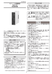
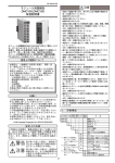
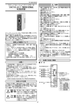
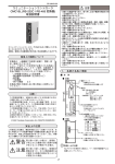
CP-UM-5129 安全上の注意 コミュニケーションコントローラ CMC10B (CPL / CPL変換器) 取扱説明書 この安全上の注意は、製品を安全に正しくお使いいただ き、あなたや他の人々への危害や財産への損害を未然に 防止するためのものです。安全上の注意は必ず守ってく ださい。また、内容をよく理解してから本文をお読みく ださい。 警告 取り扱いを誤った場合に、使用者 が死亡または重傷を負う危険の状態 が生じることが想定される場合。 注意 取り扱いを誤った場合に、使用者が 軽傷を負うか、または物的損害のみ が発生する危険の状態が生じること が想定される場合。 注意 ・本器への結線や取り付け、取り外しは必ず電源の供給 元を切った状態で行ってください。 故障の恐れがあります。 ・本器を分解しないでください。 故障の恐れがあります。 ・本器は仕様に記載された使用条件 (温度、湿度、振動、 衝撃、取り付け方向、雰囲気など) の範囲内でお使い ください。 火災、故障の恐れがあります。 ・本器の通風穴をふさがないでください。 火災・故障の恐れがあります。 ・本器への結線は定められた基準に従い、指定された電 源、および施工方法で正しく配線してください。 感電・火災・故障の恐れがあります。 ・本器のケース内部に線くず、切粉、水などが入らない ようにしてください。 火災・故障の恐れがあります。 ・端子ねじは仕様に記載されたトルクで確実に締めてく ださい。締め付けが不完全だと火災の恐れがあります。 ・本器の未使用端子を中継端子として使用しないでくだ さい。 感電・火災・故障の恐れがあります。 ・雷サージの恐れがある場合は、当社製サージノンを使 用してください。 火災・故障の恐れがあります ・本器を廃棄されるときは、産業廃棄物として各自治体 の条例に従って適切に処理してください。 コミュニケーションコントローラCMC10Bをご購入いた だき、まことにありがとうございます。 本書は、使用上の注意事項と取り扱い方法だけを説明し たものです。 詳しい取り扱い説明については別冊の コミュニケーションコントローラCMC10B (CPL/CPL変 換器) 取扱説明書「設計編」CP-SP-1064 をお読みにな り、正しくご使用ください。 使用上の制限について 本製品は、一般機器での使用を前提に、開発・設 計・製造されております。 とくに、下記のような安全性が必要とされる用途に 使用する場合は、フェールセーフ設計、冗長設計 お よび 定期点検の実施など、システム・機器全体の 安全に配慮していただいた上でご使用ください。 ・人体保護を目的とした安全装置 ・輸送機器の直接制御(走行停止など) ・航空機 ・宇宙機器 ・原子力機器 など 本製品の働きが直接人命に関る用途には使用しない でください。 お願い この取扱説明書は、本製品をお使いになる担当者のお 手元に確実に届くようにお取りはからいください。 この取扱説明書の全部、または一部を無断で複写、ま たは転載することを禁じます。この取扱説明書の内容 を将来予告なしに変更することがあります。 この取扱説明書の内容については、万全を期しており ますが、万一ご不審な点や記入もれなどがありました ら、当社までお申し出ください。 お客様が運用された結果につきましては、責任を負い かねる場合がございますので、ご了承ください。 1999 Yamatake Corporation ALL RIGHTS RESERVED J1 1. 各部の名称と機能 ■ 本 2. ■ 取り付け場所 体 Loader jack: For connecting to the Smart Loader Package (SLP-CM1E20) to set up the CMC10B Communications address setup switch: For setting the communications address for host CPL communications Set within the range 01 to 99. (factory setting: 00) POWER: Lights when power is HOST<=>CMC: Baud rate setup switch: For setting the baud rate Indicates the operatin state of host CPL communications of host CPL communications Position Baud rate 0 4800bps 1 9600bps 2 19200bps (factory setting: 0) Host CPL Communications Connector Position Signal 11 12 13 14 15 SDA SDB RDA RDB SG 取り付け 次のような所には取り付けないでください。 ・仕様の範囲を超えた高温、低温、高湿度、低湿度 になるところ ・硫化ガスなど腐食性ガスのあるところ ・粉塵、油煙などのあるところ ・直射日光、風雨が当たるところ ・仕様の範囲を超えた機械的振動、衝撃のあるところ ・高圧線の下、溶接機および電気的ノイズの発生源 の近く ・ボイラなどの高圧点火装置から15m以内 ・電磁界の影響のあるところ ・可燃性の液体や蒸気のあるところ ■ モジュールの連結 CMC<=>LOCAL: Indicates the operatin state of local CPL communications ERR: Lights at CMC10B er Reset Switch: Reset the CMC10B 本器はベース左右のコネクタで別のモジュールと連 結できます。 モジュールの連結はDINレールへの取り付け、また は、ねじ取り付けを行う前に作業してください。 連結することで、各モジュールの電源および下位 CPL通信が接続され、配線を省くことができます。 下位CPL通信は、ベースの通信切離しスイッチで切 離しができます。 ■ 取り付け方法 本器はベースをねじで取り付ける方法とDINレール に取り付ける方法のどちらでもお使いいただけます。 取扱い上の注意 ・本器は垂直な面にDINレールストッパを下側にし て取り付けてください。 ■ ベース ● ねじ取り付けの場合 ベースの取り付けねじ穴2カ所をM3ねじで固定し てください。 レバー :本体を固定します 取り付けねじ穴 :2カ所あります M3ねじでベースを 固定します 取り付けねじ穴 DINレールストッパ :DINレールに固定 するとき使用します 30+0.9 +0.3 M3 10±0.2 電源端子 78.5±0.2 5 5 (100) 通信切離しスイッチ :左側に連結した 機器と下位CPL 通信を行わない ときに使用します 出荷時は CONNECT 側 です 単位:mm (30) 番号 信号名 1 DC24V(+) 2 DC24V(−) 3 FG 下位CPL通信端子 :3線式RS-485の 接続端子です 番号 4 5 6 ● DINレール取り付けの場合 DINレールを固定した後、DINレールストッパを 十分引き出してからベースをレールに引っかけて ください。次にDINレールストッパを上方にカチ ッと音がするまで押し込んでください。 信号名 DA DB SG J2 ■ 本体をベースに取り付ける ■ 下位CPL通信(CMC⇔LOCAL)接続 フックを引っかけて、レバーがカチッと音がするま ではめ込んでください。 下位CPL通信(RS-485)は3線式接続です。 レバー 例:5線式計器との接続方法 フック 取扱い上の注意 SGは必ず接続してください。接続しないと安定し た通信ができないことがあります。 外すときは、レバーを押しながら手前に引いてくだ さい。 3. 結 ■ 上位CPL通信(HOST⇔CMC)接続 上位CPL通信はコネクタ式で接続します。 適用コネクタは、81440792-001(4個/セット) フェニックス・コンタクト(株)製MSTB2,5/5-STF5,08 AU 相当品です。 線 ■ 使用ケーブルについて RDA 11 SDA RDB 12 SDB SDA 13 RDA KPEV-S−0.9mm2×1P SDB 14 RDB ITEV-S−0.9mm2×1T SG 15 SG 推奨するツイストケーブル線 2心 (株)フジクラ 3心 CMC10B(最大31台) 親局 ・ 入出力および電源には、JCS4364弱電計装用ケー ブルをご使用ください。 (通称、計装用ツイストシールド線) IPEV-S−0.9mm2×1P KTEV-S−0.9mm2×1T ・ 電磁誘導の比較的少ない場合は、シールド付き 多心マイクロホンコード(MVVS)を使用できま す。 11 SDA ■ 結線上の注意 12 SDB 端子部の結線は必ず圧着端子を使用してください。 結線が終わったら、通電前に接続に間違いのないこ とを確認してください。 13 RDA 14 RDB ■ 電源の接続 15 SG 電源端子は次のように接続してください。 1 2 例:5線式計器との接続方法 3 取扱い上の注意 − + DC24V±10% SGは必ず接続してください。接続しないと安定し た通信ができないことがあります。 FG UL規格に適合させるためには、電源はULクラス2 電源に接続してご使用ください。 4. 設 定 本器はご使用前に次の設定をしてください。 ① 上位CPL通信に対する本器通信アドレスの設定 ② 上位CPL通信の伝送速度の設定 ③ 通信切離しスイッチの設定 ④ CPL通信の機種構成などに関する設定 この設定はローダージャックから行います。 詳細は、コミュニケーションコントローラ CMC10B (CPL/CPL変換器) 取扱説明書 「設計編」CP-SP-1064 をご覧ください。 取扱い上の注意 連結しているモジュール間は、電源が相互に接続さ れています。 連結しているモジュールのどれか一つに電源を供給 してください。 電源は、連結しているモジュールの消費電力の総和 を十分にまかなえるものを選定してください。 J3 5. 仕 ■ 仕 様 様 項 目 仕 様 通 信 種 類 HOST⇔CMC通信 CPL(RS-485 5線式) 動 作 条 件 周囲温度 0〜50℃ 周囲湿度 30〜90%RH 電源電圧 DC24V±10% 周囲温度 −20〜+70℃ 周囲湿度 10〜95%RH 振 動 4.9m/s2以下(10〜60Hz X Y Z方向各2h) 衝 ねじ取り付け状態:392m/s2以下 DINレール取り付け状態:196m/s2以下 輸 送 保 管 条 件 そ の CMC⇔Local通信 CPL(RS-485 3線式) CMC⇔PC通信 CPL(スマートローダパッケージ付属ケーブル) 撃 包装落下試験 落下高さ60cm(1角3稜6面 絶縁抵抗 50MΩ以上(DC500V絶縁抵抗計にて) 耐電圧 AC500V 1min 質 量 約300g 取り付け ねじ取り付けまたはDINレール取り付け ねじ締付トルク ・電源端子、CPL通信端子 0.8〜1 N・m ・上位CPL通信接続用コネクタ端子部 0.8 N・m ・上位CPL通信接続用コネクタ取り付け部 0.8 N・m 電源電圧 DC24V±10% 消費電力 5W 適合規格 EN61000-6-4、EN61000-6-2 別売品 スマートローダパッケージ 形番:SLP-CM1J20 他 自由落下) ■ 外形寸法図 単位:mm 〔ご注意〕この資料の記載内容は、お断りなく変更する場合も ありますのでご了承ください。 お問い合わせは、下記または当社事業所へお願いいたします。 アドバンスオートメーションカンパニー 本社 〒100-6419 北海道支店 東北支店 北関東支店 東京支社 東京都千代田区丸の内2-7-3 (011)781-5396 (022)292-2004 (048)653-8733 (03)6810-1200 中 関 中 九 部 西 国 州 支 支 支 支 社 社 店 社 東京ビル (052)238-3037 (06)6881-3383〜4 (082)222-3982 (093)952-1210 製品のお問い合わせ、計装のご相談は… コールセンター: 0466-20-2143 〈COMPO CLUBアドレス〉 http://www.compoclub.com 〈山武ホームページアドレス〉http://jp.azbil.com この資料は再生紙を使用しています。 (13) 1999年 2007年 J4 5月 初版発行(M) 6月 改 訂 9 版 ( A ) CP-UM-5129E CMC10B (CPL / CPL Converter) Communication Controller User's Manual SAFETY PRECAUTIONS Safety precautions are for ensuring safe and correct use of this product, and for preventing injury to the operator and other people or damage to property. You must observe these safety precautions. Also, be sure to read and understand the content of this user's manual. WARNING Warnings are indicated when mishandling this product might result in death or serious injury to the user. CAUTION Cautions are indicated when mishandling this product might result in minor injury to the user, or only physical damage to this product. Thank you for purchasing the Communication Controller CMC10B. This manual contains information ensuring correct use of the Communication Controller CMC10B. It also provides necessary information for installation and maintenance. This manual should be read by those who design and maintain devices that use the Communication Controller CMC10B.Be sure to keep this manual nearby for handy reference. For further details on correct use, read the Communication Controller CMC10B (CPL/CPL converter) User's Manual (Design Manual) CP-SP-1064E. CAUTION • Before wiring, removing or installing the CMC10B, be sure to turn the power OFF. Failure to do so might cause faulty operation. • Do not disassemble the CMC10B. Doing so might cause faulty operation. • Use the CMC10B within the operating ranges (temperature, humidity, voltage, vibration, shock, mounting direction, atmosphere, etc.) recommended in the specifications. Failure to do so might cause fire or faulty operation. • Do not block ventilation holes. Doing so might cause fire or faulty operation. • Wire the CMC10B properly according to predetermined standards. Also wire the CMC10B using designated power leads according to recognized installation methods. Failure to do so might cause electric shock, fire or faulty operation. • Do not allow lead clippings, chips or water to enter the CMC10B case. Doing so might cause fire or faulty operation. • Firmly tighten the terminal screws at the torque listed in the specifications. Insufficient tightening of terminal screws might cause fire. • Do not use unused terminals on the CMC10B as relay terminals. Doing so might cause electric shock, fire or faulty operation. • Use Yamatake Corporation's SurgeNon if there is the risk of power surges caused by lightning. Failure to do might cause fire or faulty operation. • When disposing of the CMC10B, dispose of it appropriately as industrial waste in accordance with bylaws and regulations. RESTRICTIONS ON USE This product has been designed, developed and manufactured for general-purpose application in machinery and equipment. Accordingly, when used in applications outlined below, special care should be taken to implement a fail-safe and/or redundant design concept as well as a periodic maintenance program. • Safety devices for plant worker protection • Start/stop control devices for transportation and material handling machines • Aeronautical/aerospace machines • Control devices for nuclear reactors Never use this product in applications where human safety may be put at risk. REQUEST Make sure that this Instruction Manual is handed over to the user before the product is used. Copying or duplicating this Instruction Manual in part or in whole is forbidden. The information and specifications in this Instruction Manual are subject to change without notice. Considerable effort has been made to ensure that this Instruction Manual is free from inaccuracies and omissions. If you should find any inaccuracies or omissions, please contact Yamatake Corporation. In no event is Yamatake Corporation liable to anyone for any indirect, special or consequential damages as a result of using this product. 2000 Yamatake Corporation ALL RIGHTS RESERVED E1 1.NAMES AND FUNCTIONS OF PARTS 2.MOUNTING ■ Mounting Locations ■ Body Avoid installing the CMC10B in the following locations: • Locations subject to low and high temperature and humidity exceeding the specified ranges • Locations subject to corrosive gases such as sulfide gases • Locations subject to dust or oil fume • Locations subject to direct sunlight, wind or rain • Locations subject to vibration or shock exceeding the specified ranges • Locations under high-voltage lines and near sources of electrical noise such as welders • Locations within 15 meters of high-voltage ignition equipment such as boilers • Locations where magnetic fields are generated • Locations near flammable liquid or steam Loader jack: For connecting to the Smart Loader Package (SLP-CM1E20) to set up the CMC10B Communications address setup switch: For setting the communications address for host CPL communications Set within the range 01 to 99. (factory setting: 00) POWER: Lights when power is ON HOST<=>CMC: Baud rate setup switch: For setting the baud rate Indicates the operating state of host CPL communications of host CPL communications Position Baud rate 0 4800bps 1 9600bps 2 19200bps (factory setting: 0) Host CPL Communications Connector Position Signal 11 12 13 14 15 SDA SDB RDA RDB SG CMC<=>LOCAL: Indicates the operating state of local CPL communications ■ Linking modules ERR: Lights at CMC10B error The CMC10B can be linked with other modules by the connectors on the left and right of the base. Modules must be linked before the CMC10B is mounted on the DIN rail or mounted by screws. By linking modules together, the power supply of each module and local CPL communications are connected, eliminating the need for wiring. Local CPL communications can be disconnected by the communications disconnection switch located on the base. Reset Switch: Reset the CMC10B ■ Mounting method The CMC10B can be mounted in either of two ways, by mounting its base by screws or by securing on a DIN rail. ■ Base Handling Precautions Lever: • Install this module so that it is vertical, with the DIN rail locking tab at the bottom. For securing the body Mounting holes (2 locations): For securing the base with M3 screws ● When mounting the base by screws Secure the two mounting holes on the base by M3 screws. Communications disconnection switch: DIN rail locking tab: Used for locking on a DIN rail 10 M3 0.2 5 5 Power supply terminal 0.2 No. Signal 1 24Vdc(+) 2 24Vdc(-) 3 FG 78.5 Mounting hole Unit:mm 30+0.9 +0.3 (100) Used for disabling local CPL communications with devices linked on the left side (factory setting: CONNECT ) (30) Local CPL communications terminal: 3-lead RS-485 connector terminal No. 4 5 6 Signal DA DB SG ● When securing on a DIN rail Secure the CMC10B on the DIN rail, fully draw out the DIN rail locking tab and hook the base onto the DIN rail. Next, push the DIN rail locking tab upwards until you hear it click into place. E2 ■ Mounting the body on the base ■ Connecting local CPL communications (CMC<=>LOCAL) Please the hook into the base and push the body into the base until you hear it click into place. Local CPL communications (RS-485) is performed using a 3-lead connection. Lever Base Hook Ex: Connection with a 5-lead device Handling Precautions Be sure to connect SG terminals each other. Failure to do so might cause unstable communications. To remove the body from the base, pull the body towards you while pressing down the lever. ■ Connecting host CPL communications (HOST<=>CMC) 3.WIRING Host CPL communications is performed using a connector. The applicable connector is 81440792-001 (set of 4) MSTB2,5/5-STF-5,08 AU made by Phoenix Contacts Ltd. or equivalent product. ■ Compensating Lead Use shielded instrument cable for instrumentation for inputs/outputs and power supply. ■ Wiring precautions Master Station Be sure to use crimped terminals for wiring terminals. When wiring is finished, check the connections for any miswiring before turning the power ON. ■ Connecting the power supply Connect the power terminal as follows: 1 24Vdc 2 10% CMC10B(Max.31 units) RDA 11 SDA RDB 12 SDB SDA 13 RDA SDB 14 RDB SG 15 SG 3 11 SDA FG 12 SDB The power supply unit must be a UL approved Class 2 power supply unit or Class 2 transformer in order to apply UL. 13 RDA 14 RDB 15 SG Handling Precautions Ex: Connection with a 5-lead device Power is mutually connected between linked modules. Supply power to one of the linked modules. Select a power supply that can cover the total power consumption of all linked modules. Handling Precautions Be sure to connect SG terminals each other. Failure to do so might cause unstable communications. 4.SETUP Set up the CMC10B as follows before use: (1) Set the CMC10B communications address for host CPL communications. (2) Set the baud rate for host CPL communications. (3) Set the communications disconnection switch. (4) Make settings relating to the CPL communications mode configuration. Make these settings via the loader jack. For details, refer to the Communication Controller CMC10B (CPL/CPL converter) User's Manual (Design Manual) CP-SP-1064E. E3 5.SPECIFICATIONS ■ Specifications Item Specifications Communications mode HOST<=>CMC communications CPL (RS-485 5-lead type) CMC<=>Local communications CPL (RS-485 3-lead type) CMC<=>PC communications Operating conditions CPL (cable provided with Smart Loader Package) Ambient temperature 0 to 50˚C Ambient humidity 30 to 90%RH Power voltage 24Vdc Transport/storage Ambient temperature -20 to +70˚C conditions Ambient humidity 10 to 95%RH Vibration resistance 4.9m/s2 max. (10 to 60 Hz, for 2h each in X, Y and Z directions) Impact resistance Screw mount: 392m/s2 max. DIN rail mount: 196m/s2 max. Package drop test Drop height 60cm (1 corner, 3 sides, 6 planes, free fall) Insulation resistance 50MΩ min. (by 500Vdc megger) Other 10% Dielectric strength 500Vac for 1min Mass Approx.300g Mounting Screw mount or DIN rail mount Screw tightening torque •Power terminal,CPL communications terminal 0.8 to 1N•m •Connector terminal for host CPL communication connection 0.8N•m •Connector mount for host CPL communication connection 0.8N•m Power voltage 24Vdc Power consumption 5W Applicable standards EN61000-6-4, EN61000-6-2 Sold separately Smart Loader Package SLP-CM1E20 ■ External Dimensions 10% Unit:mm Dimension required for mounting and removal from DIN rail Dimension required for mounting and removal of the body Specifications are subject to change without notice. Advanced Automation Company 1-12-2 Kawana, Fujisawa Kanagawa 251-8522 Japan Printed in Japan. 1st Edition: Issued in July 2000 (W) 9th Edition: Issued in June 2007 ( A ) URL: http://www.azbil.com Printed on recycled paper. (07) E4