1
®
日本文
中 文
はんだこてテスター
English
取扱説明書
このたびはハッコー FG-101をお買い求めいただき
まことにありがとうございます。
お使いになる前に必ず本書をお読みください。
また、
お読みになった後も大切に保管しておいてください。
注意:
・ 本機は、
こて先を接地していないはんだこてには使用できません。
・ 本機は、
アース端子を備えたコンセントに接続し、接地してご使用ください。
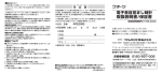
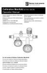
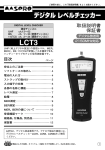
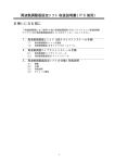
1. セット内容と部品名称
ハッコー FG-101 ..................................................1
ヒューズ ...................................................................1
伝導ワイヤー ..........................................................1
グラウンド端子 (GND)
AUTO ZEROボタン
まず最初にセットの内容をご確認ください。
センサー (10 pcs/set) ....................................... 1
グラウンドクリップ ................................................. 1
電源コード.............................................................. 1
取扱説明書 ............................................................. 1
液晶画面
モード表示
ブラインド
プレート ヒューズ
伝導ワイヤー
センサー
MAX HOLD
ボタン
SELECT ボタン
伝導プレート
保護板
コンセント
電源スイッチ
電源コード
グラウンドクリップ
English
中 文
日本文
2. 仕様
品名 FG-101
温度 分解能
測定範囲
測定許容差
センサー
電圧 分解能
測定範囲
測定許容差
抵抗 分解能
測定範囲
測定許容差
表示 LCD 表示
バーンアウト *2
消費電力
外形寸法
1℃
0 ∼ 700℃ *1
3℃(300 ∼ 600℃の範囲)
5℃(その他の温度範囲)
K (CA) 熱電対
0.1mV
0 ∼ 40 mV (AC)
(5% of reading +1 digit)
0.1Ω
0 ∼ 40Ω
(5% of reading +1 digit)
3 1/2 桁
MAX HOLD機能 ("MAX HOLD 機能 "を参照 )
2.6W
200(W) 50(H) 120(D)
mm
重量
1kg
使用温度範囲 0 ∼ 40℃、20 ∼ 90%RH、結
露なきこと
環境条件
適用定格汚染度2
(IEC/UL61010-1による)
*1 温度センサー (191-212および212C)は500℃ (932
F)までの測定にしか使用できません。
500℃ (932 F)
以上の測定を行う時は温度プローブ(5. 交換部品 /オ
プション参照)
をご使用ください。
*2 温度センサーが取り付けられていない場合や切れた場
合にバーンアウト表示になります。温度センサーが切
れた場合は新しい温度センサーと交換してください。
ま
た、測定範囲外の値が入力されたときにもバーンアウト
表示になります。
注記: ※ 本製品は中国 RoHSに対応しています.(巻末の表を参照。)
※ 仕様および外観は改良のため予告なく変更することがありますが、
あらかじめご了承ください。
3. 安全及び取扱い上のご注意
注 意
・ はんだこてのこて先やはんだ除去器のノズル温度を測定する際、こて先の温度は、200 ∼ 450℃
の高温に達します。他にも高温になる製品の温度を測定する際は、取扱いを誤るとやけど・火災の
恐れがありますので、
ご注意ください。
・ 内部点検や部品交換の際、電源プラグは必ず抜いてください。感電の恐れがあります。
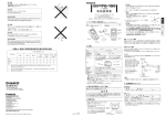
4. 使用方法
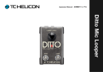
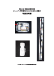
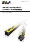
1. 付属のセンサーを取り付けます。
・ スライドボタンを押します。スライドピンが
ターミナル側へ移動します。
・ スライドピンがターミナル側へ移動した状
態で、
センサーを取り付けます。
・ センサーの赤印の付いた方を赤い表示側
のターミナルに、青印の方は、青い表示側
のターミナルに取り付けます。
スライドピン
スライドボタン
伝導プレート
センサーターミナル
注意
センサーは、非常に細い(φ0.2)CA 線で作られて
おりますので強く押すと切れる恐れがあります。丁
寧に取扱いしてください。
2
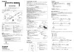
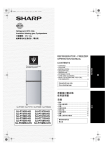
新しいはんだ
測温部
注意
・ 本体は、一部樹脂でできておりますので、こ
て先を当てない様にご注意ください。また、
ターミナルやスライドピンにも当てない様に
ご注意ください。
・ センサーの測温部には、、特殊処理をしてお
りますが、測定をくり返すうちに劣化してき
ます。正確な温度を測定するため、測温部が
消耗したものは、新しいセンサーと交換して
ください。なお、センサーの交換目安は、測
定回数約 50 回です。
・ ターミナルにフラックスが付着した時は、ア
ルコールで拭き取ってください。 (シンナー
やベンジンでは、拭かないでください。)
・ 表示温度が安定した状態で読み取ってくだ
さい。
English
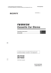
1. SELECT ボ タ ン を 押 し、 モ ー ド 表 示 を
"TEMP"にします。
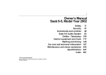
2. こて先に新しいはんだをのせて、センサーの測
温部に当ててください(右図参照)。
こて先
中 文
(1)こて先温度の測定
注記:
測定時には、こて先に新しいはんだをのせてく
ださい。温度センサーまたは伝導プレートとこ
て先の接触を確実にするために必要です。
日本文
2. 電源プラグをコンセントに差し込み、電源ス
イッチを入れます。
・ 必ずアース端子を備えたコンセントに接続
してください。
・ FG-101 本体のコンセントは、電源スイッチ
が入っているときだけ給電されます。
注意
ホットエアー (FR-802 等 ) を FG-101 に直 接当
てて、測定しないでください。直接当てた場合、
FG101 本体が破損します。
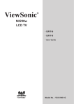
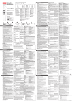
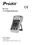
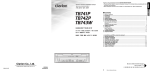
■ MAX HOLD 機能
ボタンを押すと、画面右下にMAX HOLDと
表示されます。その状態では、常に温度の最大値
が表示されるようになります。
また、
ボタンには他にも機能が付いています。
その操作方法を以下に示します。
MAX HOLD
MAX HOLD
押す
1 秒未満
1 秒以上
MAX HOLD ボタンを押す
MAX HOLD
操作方法
ボタンには、ボタンを短く押した時のMAX 温
度更新機能と、ボタンを長く押した時の解除機能
があります。
・ 短く押した時(1 秒未満)
MAX HOLD 状 態では常に MAX 温 度のみ
が表示されますが、ボタンを短く押した時、表
示値が一度リセットされ、ボタンを押した後の
MAX 温度が表示されるようになります。
・ 長く押した時(1 秒以上)
MAX HOLD 機能が解除され、通常表示に戻り
ます。
MAX HOLD
MAX HOLD
MAX HOLD
MAX HOLD
ボタンを押す
1 秒未満
非表示
MAX HOLD
機能が解除さ
れます。
MAX HOLD
MAX 温度が更新されます。
注意
・ どの状態からでも電源を一度 OFFにすると、次回
電源投入時は通常表示に戻ります。
・ MAX HOLD 機能は、温度測定時のみ有効です。
3
English
中 文
日本文
(2)こて先 -アース間の電位差
1. 測定するはんだこての電源プラグを、FG-101
本体のコンセントに差し込みます。
2. こて先が設定温度、または、設定温度を可変
できるタイプは、最高温度に設定し、最高温度
に到達するのを待ちます。
3. SELECTボタンを押し、モード表示を"mV"にし
ます。
4.
ボタンを押します。("AUTO ZERO 機能 "を
参照 )
5. こて先をクリーニングして、新しいはんだをのせ
ます。
6. 伝導プレートの中央部にはんだを盛り、
良好な
はんだぬれが形成されるまで加熱します。
7. 表示が安定したら読み取ります。
AUTO ZERO
注記:
注記:
電圧測定時、伝導プレートにこて先をあてない時、
数値が表示されますが、故障ではありません。ま
た、測定範囲外の値が入力された時、測定範囲外
の値が表示される場合もありますが、故障ではあ
りません。
熱容量の小さいこて先で、こて先温度が低い
など伝導プレートではんだが溶けにくい場合
は、付属の伝導ワイヤーをご使用ください。
交換方法
伝導プレートを取り付けているネジを2 本は
ずし、伝導プレートを伝導ワイヤーに交換後、
はずしたネジで取り付けてください。
(3)こて先 -アース間の抵抗
SELECT ボタンを押し、モード表示を"OHM"にします。「こて先 -アース間の電位差」の測定と同じ
要領で、
ボタンを押して、
その後抵抗値を測定します。
AUTO ZERO
注意
・ 電圧、抵抗の測定時は、本体電源コードは必ず、接地された二極接地型コンセントに接続してくだ
さい。
・ 電圧、抵抗測定の結果が規定以上の値が出たときは、はんだこてのこて先や取付ネジのゆるみなど
を確認し、再度測定してください。
■ AUTOZERO 機能
・ mVとOHMは、
それぞれのモードで行う必要があります。
・
ボタンを押しますと、0.0.0 → 0.0 → 0 とカウントされます。通常表示に戻るまでお待
ちください。
・ AUTOZEROによる補正値は、本体に記録されます。電源を切っても補正値は次回からも有
効です。
AUTO ZERO
4
● グラウンド端子
測定するはんだこてがワニ口クリップなどで接地するタイプの場合は、
このグラウンド端子に、
グラウン
ドクリップで接続してください。
English
5. 交換部品/オプション
● ハッコー FG-101
品番
B1752
B1754
B1950
B2468
B2387
191-212
部品名
伝導プレート
グラウンドクリップ
伝導ワイヤー
ヒューズ/ 125V-5A
電源コード
センサー/鉛フリー対応
中 文
・ 伝導プレートの交換は、取付ネジを外して行なってください。
・ 温度センサーの寿命は使用する温度やはんだ、フラックスの成分によって変わります。50 回程度
を目安として、測温部が消耗したら交換してください。
・ 校正は弊社が有償にて承ります。本機をお求めになった販売店、代理店にお申し付けください。
日本文
● メンテナンスと校正
● オプション
品番
部品名
191-212C センサー/鉛フリー対応
校正証明書付き
A1310 *3 はんだ槽温度プローブ
C1220 自動機用温度プローブ
10 ヶ
10 ヶ
*3 はんだ槽用のプローブです。従来の温度センサーを外
し、温度プローブのコネクターの赤、青の色を合わせ
て、FG-101 本体のターミナルに差し込みます。
プロー
ブの先をはんだの中に入れ、測定します。
5
日本文
®
English
中 文
焊鐵測試儀
使用說明書
承蒙惠顧 , 謹致謝忱。使用 HAKKO FG-101 之前 , 請詳閱本使用說明書 ,
正確使用。閱後請妥為收存 , 以備日後參閱。
注意
●如果焊鐵未接地 , 不可使用 HAKKO FG-101。
●將本測試儀插入接地 (3 孔 ) 插座使用。
1. 包裝清單
請先確認包裝的內容。
HAKKO FG-101 ...................................................... 1
保險絲 ...................................................................... 1
傳導線 ...................................................................... 1
溫度傳感器 (10 pcs/set) ......................................... 1
多功能插頭 ..............................................................1
歐式插頭 ..................................................................1
接地夾 .......................................................................1
電源線 .......................................................................1
使用說明書 ..............................................................1
接地終端 (GND)
顯示屏
AUTO ZERO
按鈕
模式表示燈
環板
保險絲
傳導線
MAX HOLD
按鈕
溫度傳感器
接地夾
選擇按鈕
插座
導電板
電源開關
保護板
多功能插頭
歐式插頭
注記:
多功能插頭和歐式插頭按地區提供。
6
電源線
2. 規格
功率消耗
English
*1 溫度傅感器 (191-212) 是可以使用至 500℃ (932 ℉ )。
如果測定 500℃ (932 ℉ ) 以上時 , 請使用溫度探針 ( 請
參照 5. 部件清單 )。
*2 未安裝溫度傳感器時或是斷線時 , 會顯示傳感器損
壞。溫度傳感器斷線時請更換新的溫度傳感器。又 ,
測定範圍外之值被輸入時也會顯示傳感器損壞。
中 文
外形尺寸
重量
操作環境
環境條件
100V-2.6W, 110V-2.9W, 120V-2.6W,
220V-2.7W, 230V-2.8W, 240V-3.0W
200(W)×50(H)×120(D) mm
1kg
0 ~ 40℃ , 20 ~ 90%RH ( 無結露 )
適用規格污染度 2 ( 基于 IEC/UL
61010-1)
日本文
名稱 HAKKO FG-101
溫度 分解
1℃
測試範圍
0 ~ 700℃ *1
精確度
±3℃ (300 ~ 600℃之間 )
±5℃ ( 其他溫度範圍 )
傳感器
K (CA) 溫差電偶
電壓 分解
0.1mV
測試範圍
0 ~ 40 mV (AC)
精確度
±(5% +1 數位 )
電阻 分解
0.1Ω
測試範圍
0 ~ 40Ω
精確度
±(5% +1 數位 )
顯示 液晶顯示 (LCD) 3 1/2 數位
傳感器損壞顯示 *2
MAX HOLD
(請參照 "MAX HOLD功能")
注記:
* 本產品有適應中國 RoHS 指令。( 參閱最末尾頁“產品
中有毒有害物質或元素的名稱及含量”)
* 規格及外觀可能改良變更 , 恕不先行通知。
3. 安全及使用上的注意事項
注意
· 測量焊鐵的焊鐵頭和吸錫器的吸嘴溫度時 , 焊鐵頭的溫度會高達 200~450℃。
測量其它高溫產品時 , 濫用可能導致灼傷或火患 , 請注意。
· 內部檢查或更換部件時 , 請務必拔掉電源插頭 , 以免發生觸電。
4. 使用方法
1. 安裝附帶的傳感器。
· 按下滑鈕 , 可動杆向終端方向移動。
· 在可動杆移動到終端方向的狀態下 , 將傳感
器安裝到可動杆上。
· 將傳感器紅邊置入紅色終端 , 藍邊置入藍色
終端。
可動杆
滑鈕
導電板
終端
注意
應小心使用溫度傳感器。溫度傳感器非常纖細 , 外徑
為 0.2, 太用力可能損壞傳感器。
7
注記:
測試前應在焊鐵頭塗上新焊錫。這是為了確保焊鐵
頭 , 溫度傳感器和導電板之間的良好接觸。
English
中 文
日本文
2. 將插頭插入電源插座 , 打開開關。
· 確保插頭插入接地 (3 孔 ) 插座。
· HAKKO FG-101 本機的插頭座是只有打開開
關後才供給電源。
(1) 測試焊鐵頭溫度
焊鐵頭
1. 按選擇按鈕 , 把模式切換到 "TEMP" 模式。
2. 在焊鐵頭送上新的焊錫後把焊鐵頭放在傳感器
上。
新焊錫
測試點
注意
·本機的一部分是用塑料制成 , 請注意不要用
焊鐵頭觸及。另外請注意也不要用焊鐵頭
碰觸終端和可動杆。
·傳感器的測溫部有進行特殊處理 , 但反復測
量會導致傳感器老化。為了測量出正確的
溫度 , 請更換測溫部已損耗的傳感器。另
外 , 傳感器的更換標準大約為測量次數 50
次。
·終端上粘附了助焊劑時 , 請用酒精擦拭。( 請
不要用稀釋劑和汽油擦拭。)
·溫度顯示穩定後 , 再辨認。
注意
請勿將熱風機 (FR-802 等 ) 直接吹向 FG-101 來進行
測定。直接吹的話 , 會使 FG-101 主機受損。
■ MAX HOLD 功能
按下
按鈕 , 畫面右下方則顯示 MAX
HOLD。此狀態下顯示溫度最大值。另外 ,
MAX HOLD
MAX HOLD
按鈕還具備其它功能。操作方法如下所
述。
操作方法
短時間按下
按鈕時 , 具有 MAX 溫度更新
功能 , 長時間按下
按鈕時具有解除功能。
MAX HOLD
MAX HOLD
( 不超過 1 秒 )
MAXHOLD 狀態下僅顯示 MAX 溫度 , 但短
時間按下
按鈕時 ,MAX 溫度會重新設
置一次 , 顯示按下按鈕後的 MAX 溫度。
按下
不超過 1 秒
按下
·短時間按下時
MAX HOLD
·長時間按下時
(1 秒以上 )
MAX HOLD 功能解除 , 返回通常顯示。
· 無論在何種狀態下關閉電源一次 , 下次投入
電源時就會返回通常顯示。
· MAX HOLD 功能只有在測定溫度時有效。
8
MAX HOLD
MAX HOLD
按下
不超過 1 秒
MAX HOLD
注記:
按鈕
1 秒以上
MAX 溫度更新。
按鈕
不顯示
MAX HOLD
功能解除。
(2) 測試焊鐵頭和接地之間的電
勢差。
日本文
1. 將測試的焊鐵臺的電源插頭插入 HAKKO
FG-101 插座。
2. 等候焊鐵頭昇溫到設定溫度。如果焊鐵是選用
可變更溫度的焊鐵頭款型 , 應將溫度設定在最
高溫度。
中 文
3. 按下選擇按鈕 , 把模式改換到 "mV" 模式。
4. 按下
AUTO ZERO
按鈕。( 請參照 "AUTO ZERO 功能 ")
5. 清理乾淨焊鐵頭並送上新焊錫。
7. 當顯示屏穩定時 , 閱讀電值。
注記:
如果使用熱量較小的焊鐵頭或焊鐵頭設立溫度
較低時焊錫將不容易熔化 , 此時請使用附屬的
傳導線。導電板是符合 MIL-STD-2000 規格而製
造的。因此除了上述情況以外 , 請使用導電板。
注記:
測定電壓時 , 如果焊鐵頭未接觸傳導板的話 , 不會
顯示數值 , 但是並非故障。又 , 測定範圍外之值被
輸入時 , 有時也會顯示測定範圍外之值 , 但是並非
故障。
English
6. 放置一小點焊錫在導電板中心 , 然後至到錫點
完全溶化為止。
更換方法
1. 解開裝置在導電上的兩個小螺釘。
2. 解開導電板。
3. 更換導電板後 , 再裝回小螺釘。
(3) 測試焊鐵頭和接地之間的電阻
按下選擇按鈕 , 把模式切換到 "OHM" 模式。測定方法如同 " 測試焊鐵頭和接地間的電勢差 ", 按下
AUTO ZERO
按鈕後測量電阻值。
注意
·測試電壓和電阻時 , 應確保電線插頭插入接地 (3 孔 ) 插座。
·如果所測試電壓和電阻值大過設定電阻值時 , 應檢查焊鐵頭 , 確保焊鐵的拴緊螺絲未鬆脫 , 然後再
測試。
■ AUTO ZERO 功能
· mV 和 OHM 模式需一項一項執行。
·當按下
按鈕時 , 會出現 0.0.0 → 0.0 → 0 模式顯示。請稍候至回復到通常表示。
· AUTO ZERO 的補正值記錄在 FG-101 本機上 , 即使關閉電源後 , 下次使用時補正值也有效。
AUTO ZERO
●接地終端 (GND)
如使用鱷夾接地的焊鐵時 , 應將鱷夾連接接地終端 (GND)。
9
English
中 文
日本文
●保養和校準
10
・ 更換導電板時 , 要鬆脫螺絲。
・ 溫度傳感器的壽命受使用溫度、焊錫及助焊劑的成份的影響。一般傳感器的測試次數為 50 次 ,
測溫部有損耗的話請更換後使用。
・ 此測試儀敝公司可以有償校正。詳細情況請聯系您購買的代理店。
5. 部件清單
●選購部品
● HAKKO FG-101
編號
B3213
B3214
B1752
B1754
B1950
B1258
B2468
191-212
B2419
B2421
B2422
B2424
B2425
B2426
B2436
B3508
名稱
多功能插頭
歐式插頭
導電板
接地夾
傳導線
保險絲 /250V-3.15A
保險絲 /125V-5A
傳導線 / 無鉛對應
電源線三芯美國式插頭
電源線三芯沒有插頭
電源線三芯英國標準插頭
電源線三芯歐洲式插頭
電源線三芯英國標準插頭
電源線三芯奧洲式插頭
電源線三芯中國式插頭
電源線三芯美國式插頭
規格
編號
A1310 *3
C1220
名稱
適用於測量焊錫槽溫度探針
適用於測量自動機器溫度探針
規格
*3 焊錫槽專用探針。將傳感器拆下 , 再把探針連接部的紅色對紅
色終端 , 籃色對籃色終端連接到 FG-101 機身 , 然後用探針前
端插入錫爐即可測量溫度。
10 個
美國用
印度
220V KTL, 230V CE
230V CE
中國
®
日本文
中 文
Soldering Tester
Thank you for purchasing the HAKKO FG-101 Soldering Tester.
Be sure to read these instructions before using your HAKKO FG-101,
and keep the instructions handy for reference during use.
English
Instruction Manual
CAUTION
The HAKKO FG-101 cannot be used with ungrounded soldering irons.
Ground the HAKKO FG-101by plugging it into a grounded (3-hole) outlet.
1. PACKING LIST
Please check that all items listed below
are included in the package.
HAKKO FG-101 ...........................................1
Fuse ............................................................1
Conduction Wire ..........................................1
Sensor (10 pcs/set) .....................................1
Ground terminal (GND)
AUTO ZERO button
Multi-adapter .............................................. 1
European Adapter ...................................... 1
Ground Clip ................................................ 1
Power cord ................................................. 1
Instruction Manual ...................................... 1
LCD
Mode indicator
lamp
Blind plate
Fuse
Conduction wire
MAX HOLD
button
Sensor
Ground clip
SELECT button
Conduction plate
Receptacle
Power switch
Protection plate
Multi-adapter
European
adapter
Power cord
NOTE:
The Multi-adapter and the European adapter may not be
included depending on the type of electrical connection used in
your country.
11
English
中 文
日本文
2. SPECIFICATIONS
Model Name HAKKO FG-101
Temperature Resolution
Measurement Range
Precision
Voltage
Registance
Display
Sensor
Resolution
Measurement Range
Precision
Resolution
Measurement Range
Precision
LCD
Burnout*2
MAX HOLD
Power Consumption
Dimensions
Weight
Ambient Temperature/Humidity Range
Environmental condition
1°C (1°F)
0 - 700°C (32 - 1300°F) *1
±3°C (300 to 600°C)/±6°F (572 to 1112°F)
±5°C/10°F (other than above)
K (CA) type thermocouple
0.1mV
0 to 40 mV (AC)
±(5% of reading +1 digit)
0.1Ω
0 to 40Ω
±(5% of reading +1 digit)
3 1/2 digits
(Refer to "MAX HOLD function.")
100V-2.6W, 110V-2.9W, 120V-2.6W, 220V-2.7W, 230V-2.8W, 240V-3.0W
200(W)×50(H)×120(D) mm /7.9(W)×2.0(H)×4.7(D) in
1kg
0 - 40°C (32 - 104°F), 20 - 90%RH (without condensation)
Applicable rated pollution degree 2 (According to IEC/UL61010-1)
*1 Temperature sensor (191-212) can only be used to measure temperatures below 500°C (932°F). To measure
higher temperatures, use an applicable temperature probe (see "5. REPLACEMENT PARTS AND OPTIONS").
*2 When a sensor is not attached or it burns out, the alarm symbol of Burnout (-1) is displayed. If the sensor
burns out, replace it with a new one. The same symbol is also displayed when a temperature outside the
measurement range is detected.
Note: * This product meets China RoHS requirements. (See the table at the end of this manual.)
* The specifications may be subject to change without notice.
3. SAFETY NOTICE
CAUTION
When measuring the temperature of the soldering iron tip or de-soldering nozzle, pay great
attention to the temperature of the tip or nozzle that will be as high as 200 to 450°C (392 to
842°F). Careless handling of such a hot object may result in a burn or fire.
Disconnect the power cord before service/maintenance procedures. Failure to do so may
result in electric shock.
4. OPERATION
1. Attach the sensor:
• Press the slide button to move the slide
pin closer to the terminal side.
• While holding down the slide pin, attach a
sensor to the slide pin and terminals.
• Connect the red connector of the sensor to
the red terminal and the blue connector to
the blue terminal.
12
Slide pin
Conduction
plate
Sensor terminals
Slide button
CAUTION
Handle the sensor with care. Tough handling may
break the CA sensor wire as it is as thin as 0.2
mm in diameter.
NOTE:
Use the iron tip coated with fresh solder when
performing mesurement to ensure contact
between the temperature sensor or the
conduction plate and the tip.
CAUTION
• Do not bring the iron tip into contact with the
resin components including terminals and
slide pin of the tester.
• The measuring point of the sensor generally
undergoes degradation as a result of
repeated measurement activities. It is
recommend that the sensor be replaced
every 50 measurements as a guideline to
ensure measurement accuracy.
• If the terminals are contaminated with the
soldering flux, wipe them clean with alcohol.
Do not use thinner or benzin for cleaning.
• Please read when the temperature
stabilizes.
MAX HOLD function
When pressing the
button, "MAX
HOLD" is displayed at the lower right of
appears, the
the LCD. As long as
maximum temperature will stay displayed.
MAX HOLD
Tip
English
1. Press the SELECT button to light up the
mode indicator lamp of "TEMP."
2. Place the tip coated with fresh solder on the
measuring point (Refer to the figure at right).
中 文
(1) Measuring the tip temperature
日本文
2. Insert the power cord into the outlet at the
back of the body and turn the power switch on.
• Be sure to insert the power plug into a
grounded (3-hole) outlet.
• Power will be supplied through the
receptacle on the HAKKO FG-101 only
when the power switch is turned on.
Fresh solder
Measuring point
CAUTION
Do not directly contact the FG-101 with hot air
(FR-802, etc.), during measurement. Direct
contact with hot air can damage the FG-101.
MAX HOLD
OPERATION
The
button provides two additional
functions: The max. temperature update
function when quickly pressing the button
and the MAX HOLD cancellation function
when pressing the button longer.
• Quickly pressing the
button for less
than one second, with "MAX HOLD"
displayed, updates the maximum
temperature. See the figure to the right.
MAX HOLD
MAX HOLD
Press
less than 1 second
Press the MAX HOLD button for
1 second or more
MAX HOLD
• With "MAX HOLD" displayed, pressing the
button for longer than one second cancels the
MAX HOLD function. See the figure to the right.
MAX HOLD
Press the MAX HOLD button for
less than 1 second
MAX HOLD
"MAX HOLD"
disappears
indicating the
function is
cancelled.
MAX HOLD
Max. temperature is updated.
NOTE:
• Turning off the power always cancels the
MAX HOLD function.
• The MAX HOLD function can only be used
during the temperature measurement.
13
English
中 文
日本文
(2) Measuring the difference in potential between tip and ground
1. Insert the power cord of the soldering iron to
be tested into the receptacle on the HAKKO
FG-101.
2. Wait until the tip reaches the set temperature.
If the soldering iron is a variable tip
temperature model, set temperature to the
maximum.
3. Press the SELECT button to light up the
mode indicator lamp of "mV."
4. Press the
button. (Refer to "AUTO
ZERO function.")
5. Clean the tip and coat it with fresh solder.
6. Place a tiny bead of solder in the center of
the conduction plate and heat the bead until
the solder has completely melted.
7. Read the value, when the displayed value
becomes stable.
AUTO ZERO
NOTE:
When using fine tips the solder may not melt
on the conduction plate. If this occurs, replace
the conduction plate with the conduction wire.
Do not use the conduction wire for larger tips.
NOTE:
The tester may provide a numeric value during
voltage measurement, even if the tip is not
in contact with the conduction plate. This
does not mean a failure of the tester. Also,
if a temperature outside the measurement
range is detected, a value that is outside the
measurement range may be displayed. This
does not mean a failure of the tester.
Replacement
Remove the two screws which secure
the conduction plate. After removing the
conduction plate, secure the conduction
wire with the same secrews in place of the
conducion plate.
(3) Measuring the Resistance Between Tip and Ground
Press the SELECT button to light up the mode indicator lamp of "OHM." Using the same
procedure as when measuring the difference in potential, measure the resistance after pressing
the
button.
AUTO ZERO
CAUTION
• Be sure to plug the tester power cord in a bipolar grounded outlet during voltage or resistance
measurement.
• If the measured voltage or resistance is out of the specified range, check the iron tip or mounting
screws for looseness and repeat the measurement.
AUTO ZERO function
• Voltage and resistance must be measured in respective modes.
• When pressing the
button you will see a count transition of 0.0.0 → 0.0 → 0. Wait until
the display returns to normal status.
• A correction value obtained by the AUTO ZERO function is saved in nonvolatile memory and
is not lost even when the tester is shut off.
AUTO ZERO
14
Ground terminal (GND)
When using a type of soldering iron that is grounded with an alligator clip, connect the clip to the
GND terminal.
English
5. PARTS LIST
HAKKO FG-101
Item No.
B3213
B3214
B1752
B1754
B1950
B1258
B2468
191-212
B2419
B2421
B2422
B2424
B2425
B2426
B2436
B3508
Part Name
Multi-adapter
European Adapter
Conduction Plate
Ground Clip
Conduction Wire
Fuse/250V-3.15A
Fuse/125V-5A
Sensor/Lead free
Power cord, 3 wired cord &
American plug
Power cord, 3 wired cord
but no plug
Power cord, 3 wired cord &
BS plug
Power cord, 3 wired cord &
European plug
Power cord, 3 wired cord &
BS plug
Power cord, 3 wired cord &
Australian plug
Power cord, 3 wired cord &
Chinese plug
Power cord, 3 wired cord &
American plug
中 文
• To replace the conduction plate, remove the set screws.
• The life of the temperature sensor will vary depending on the temperature at which
measurements are made and the type of solder and flux being used. In general, temperature
sensors can be used for 50 measurements. Replace the sensor as soon as the measuring
point wears out.
• HAKKO can calibrate the instrument for a nominal fee. Please contact your dealer for further
information.
日本文
Maintenance and Calibration
Spec.
10 pcs.
U.S.A.
Optional Parts
Part No.
Part Name
A1310 *3 Temperature Probe for
soldering pot
C1220
Temperature Probe for
automatic solder machine
Spec.
*3 Remove the standard sensor, and connect the red
connector of this option to the red terminal of the
HAKKO FG-101 and the blue connector to the blue
terminal. Insert the top of the probe into solder to
measure the temperature.
India
220V KTL
230V CE
230V CE
China
15