1
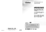
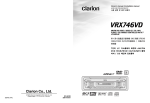
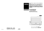
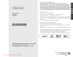
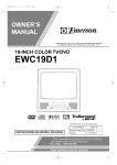
1.
2.
3.
4.
5.
6.
7.
IN-DASH WIDE 7" COLOR LCD TV
CONTROLS .................................................................................................................................. 3
FEATURES ................................................................................................................................... 4
PRECAUTIONS ............................................................................................................................ 5
BUTTON TERMINOLOGY ........................................................................................................... 6
CAUTIONS ON HANDLING ......................................................................................................... 7
Concerning the LCD screen .......................................................................................................... 7
Cleaning ........................................................................................................................................ 7
Concerning the wide screen ......................................................................................................... 7
REMOTE CONTROL .................................................................................................................... 8
OPERATION ............................................................................................................................... 10
Basic Operations ......................................................................................................................... 10
TV Mode Operations ................................................................................................................... 13
TROUBLESHOOTING ............................................................................................................... 17
SPECIFICATIONS ...................................................................................................................... 19
IN-DASH
(可藏入儀表板中)
7 英寸寬型彩
IN-DASH(可藏入儀表板中)
(可藏入儀表板中)7
(液晶顯示)電視機
LCD(液晶顯示)電視機
色LCD
8.
9.
와이드 7인치 컬러 LCD TV 계기반
• Installation and Wire connection manual
1.
2.
3.
4.
5.
6.
7.
8.
9.
BEFORE STARTING ..................................................................................................................
PACKAGE CONTENTS .............................................................................................................
GENERAL CAUTIONS ...............................................................................................................
CAUTIONS ON INSTALLATION ................................................................................................
INSTALLING THE MAIN UNIT ...................................................................................................
REMOVING THE MAIN UNIT .....................................................................................................
CAUTIONS ON WIRING ............................................................................................................
WIRE CONNECTIONS ...............................................................................................................
SAMPLE SYSTEMS ...................................................................................................................
Clarion Co., Ltd.
Be sure to unfold and read the next page.
All Rights Reserved. Copyright © 2004: Clarion Co., Ltd.
2004/3 (A·C)
QZ7532K
280-8089-00
2
TB741P/TB742P/TB743W
21
21
21
22
23
25
25
26
28
Owner’s manual
Owner’s manual
■ Contents
• Owner’s manual
English
사용 설명 및 설치 설명서
English
Owner’s manual & Installation manual
Thank you for purchasing the Clarion TB741P/TB742P/TB743W.
* Please read this Owner’s manual & Installation manual in its entirety before proceeding with wire
connection and installation.
* After reading this manual, be sure to keep it in a handy place (e.g., glove compartment).
1.
2.
3.
4.
5.
6.
7.
IN-DASH WIDE 7" COLOR LCD TV
CONTROLS .................................................................................................................................. 3
FEATURES ................................................................................................................................... 4
PRECAUTIONS ............................................................................................................................ 5
BUTTON TERMINOLOGY ........................................................................................................... 6
CAUTIONS ON HANDLING ......................................................................................................... 7
Concerning the LCD screen .......................................................................................................... 7
Cleaning ........................................................................................................................................ 7
Concerning the wide screen ......................................................................................................... 7
REMOTE CONTROL .................................................................................................................... 8
OPERATION ............................................................................................................................... 10
Basic Operations ......................................................................................................................... 10
TV Mode Operations ................................................................................................................... 13
TROUBLESHOOTING ............................................................................................................... 17
SPECIFICATIONS ...................................................................................................................... 19
IN-DASH
(可藏入儀表板中)
7 英寸寬型彩
IN-DASH(可藏入儀表板中)
(可藏入儀表板中)7
(液晶顯示)電視機
LCD(液晶顯示)電視機
色LCD
8.
9.
와이드 7인치 컬러 LCD TV 계기반
• Installation and Wire connection manual
1.
2.
3.
4.
5.
6.
7.
8.
9.
BEFORE STARTING ..................................................................................................................
PACKAGE CONTENTS .............................................................................................................
GENERAL CAUTIONS ...............................................................................................................
CAUTIONS ON INSTALLATION ................................................................................................
INSTALLING THE MAIN UNIT ...................................................................................................
REMOVING THE MAIN UNIT .....................................................................................................
CAUTIONS ON WIRING ............................................................................................................
WIRE CONNECTIONS ...............................................................................................................
SAMPLE SYSTEMS ...................................................................................................................
Clarion Co., Ltd.
Be sure to unfold and read the next page.
All Rights Reserved. Copyright © 2004: Clarion Co., Ltd.
2004/3 (A·C)
QZ7532K
280-8089-00
2
TB741P/TB742P/TB743W
21
21
21
22
23
25
25
26
28
Owner’s manual
Owner’s manual
■ Contents
• Owner’s manual
English
사용 설명 및 설치 설명서
English
Owner’s manual & Installation manual
Thank you for purchasing the Clarion TB741P/TB742P/TB743W.
* Please read this Owner’s manual & Installation manual in its entirety before proceeding with wire
connection and installation.
* After reading this manual, be sure to keep it in a handy place (e.g., glove compartment).
English
English
1. CONTROLS/控制器/컨트롤
Owner’s manual
Owner’s manual
Note: Be sure to spread this page and refer to the front diagrams when you read each chapter.
注意:在您閱讀每一章時請把本頁打開,併與前視圖對照。
참고: 이 페이지를 펼쳐두고, 각 장을 읽을때 전면 그림을 참조하도록 하십시오.
LCD panel
LCD顯示屏
LCD 패널
2. FEATURES
■
■
■
■
■
■
■
■
■
■
7" Wide (16:9) TFT Active Matrix Color LCD Panel
4 Modes Supported: Cinema, Wide, Full Wide and Normal
Wide Viewing Angle, Low Reflection and High-brightness Panel Employed
Fully-Motorised Mechanism
Preset Tuning (total of 12 stations), Manual Tuning and Automatic Tuning
Facilities for Speedy Selection of Any Broadcast Station
Very Easy and Functional Operation
Built-in 4-channel Diversity Unit
2 AV input (RCA/DIN)
1 AV output (RCA)
RADIO ANT IN/OUT (TB741P, TB742P only)
따로 판매하는 접속용 부품
▒ TV 안테나 (첨가되는 영상용 안테나)
모델 번호
적용
시스템 번호
주목
ZCP-104
자동차용의 TV 안테나
4
부스터 장착의 필름 형식
안테나
ZCA-404
자동차용의 TV 안테나(다양성)
4
왼쪽 오른쪽의 1 세트
(신축성 자재)
ZCP-100
자동차용의 TV 안테나(다양성)
4
부스터 장착
ZCB-303
자동차용의 TV 안테나(다양성)
2
* 위에서 언급한 리스트에 다양한 전환 어댑터, 확장 코드, 안테나 및 다른 부품을 첨가해도 유효합니다. 상
세한것은, 구입처나 가까운 Clarion 서비스 계열 판매점과 상의하십시오.
w
a
d
z
[BND]
[SENSOR]
[PWR]
[RESET]
[DISP]
[OPEN/CLOSE]
[PS]
[TILT]
[MEMO]
[ADJ]
3
TB741P/TB742P/TB743W
4
TB741P/TB742P/TB743W
TB741P/TB742P/TB743W
81
English
English
1. CONTROLS/控制器/컨트롤
Owner’s manual
Owner’s manual
Note: Be sure to spread this page and refer to the front diagrams when you read each chapter.
注意:在您閱讀每一章時請把本頁打開,併與前視圖對照。
참고: 이 페이지를 펼쳐두고, 각 장을 읽을때 전면 그림을 참조하도록 하십시오.
LCD panel
LCD顯示屏
LCD 패널
2. FEATURES
■
■
■
■
■
■
■
■
■
■
7" Wide (16:9) TFT Active Matrix Color LCD Panel
4 Modes Supported: Cinema, Wide, Full Wide and Normal
Wide Viewing Angle, Low Reflection and High-brightness Panel Employed
Fully-Motorised Mechanism
Preset Tuning (total of 12 stations), Manual Tuning and Automatic Tuning
Facilities for Speedy Selection of Any Broadcast Station
Very Easy and Functional Operation
Built-in 4-channel Diversity Unit
2 AV input (RCA/DIN)
1 AV output (RCA)
RADIO ANT IN/OUT (TB741P, TB742P only)
따로 판매하는 접속용 부품
▒ TV 안테나 (첨가되는 영상용 안테나)
모델 번호
적용
시스템 번호
주목
ZCP-104
자동차용의 TV 안테나
4
부스터 장착의 필름 형식
안테나
ZCA-404
자동차용의 TV 안테나(다양성)
4
왼쪽 오른쪽의 1 세트
(신축성 자재)
ZCP-100
자동차용의 TV 안테나(다양성)
4
부스터 장착
ZCB-303
자동차용의 TV 안테나(다양성)
2
* 위에서 언급한 리스트에 다양한 전환 어댑터, 확장 코드, 안테나 및 다른 부품을 첨가해도 유효합니다. 상
세한것은, 구입처나 가까운 Clarion 서비스 계열 판매점과 상의하십시오.
w
a
d
z
[BND]
[SENSOR]
[PWR]
[RESET]
[DISP]
[OPEN/CLOSE]
[PS]
[TILT]
[MEMO]
[ADJ]
3
TB741P/TB742P/TB743W
4
TB741P/TB742P/TB743W
TB741P/TB742P/TB743W
81
CAUTION
1. When the inside of the car is very cold and
the player is used soon after switching on
the heater, moisture may form on the disc or
the optical parts of the player and proper
playback may not be possible. If moisture
forms on the disc, wipe it off with a soft cloth.
If moisture forms on the optical parts of the
player, do not use the player for about one
hour and the condensation will disappear
naturally to allow normal operation.
2. Driving on extremely bumpy roads which
cause severe vibration may cause the sound
to skip.
• TV signals are strongly linear, so
reception is affected by buildings,
mountains, and other obstacles.
• Such external factors as electric train
lines, high voltage lines, and signal
devices may disturb the picture or cause
noise.
∗ If the reception is poor, switch to a station
with good reception.
CHANGES OR MODIFICATIONS TO THIS
PRODUCT NOT APPROVED BY THE
MANUFACTURER WILL VOID THE WARRANTY.
TB741P/TB742P/TB743W
5
Owner’s manual
For your safety, the driver should not watch
the TV or operate the controls while driving.
Please note that watching and operating the
TV while driving is prohibited by law in
some countries. Also, while driving, keep
the volume to a level at which external
sounds can be heard.
3. This unit uses a precision mechanism. Even
in the event that trouble arises, never open
the case, disassemble the unit, or lubricate
the rotating parts.
4. TV broadcast reception
When receiving TV broadcasts, the strength
of the signals changes since the car is
moving, so in some cases it may not be
possible to receive clear pictures.
English
3. PRECAUTIONS
English
4. BUTTON TERMINOLOGY
Note: Be sure to read this chapter referring to the front diagrams of chapter “1. CONTOROLS” on page 3
(spread).
Owner’s manual
[OPEN/CLOSE] button
[BND] button
• Use this button to open/close the liquid crystal
panel.
• Press and hold this button for about 2
seconds or longer so that the liquid crystal
panel is positioned horizontally when the
liquid crystal panel is open. Press the button
again to return the panel to the original
position. Even if the button is not pressed, the
panel returns to the original position after
about 10 seconds.
• Press this button to switch the receiving
bands.
• Press and hold this button for 1 second or
longer to turn on/off the monitor.
• Press this button to return to the previous
screen in the adjustment menu screen.
[TILT] button
• Use this button to adjust the angle of the
liquid crystal panel in 5 steps.
• Each time this button is pressed and held for
about 2 seconds or longer, the liquid crystal
panel moves forward/backward in 3 steps.
[a], [d] buttons
• Press to perform the Manual tuning operation.
• Press and hold for 1 second or longer to
perform the Seek tuning operation.
• Press to select the desired mode in
adjustment menu screen.
[w], [z] buttons
• Press to select the preset channel.
• Press to select the desired menu in
adjustment menu screen.
[ADJ] button
• Shows the ADJUST MODE menu to change
the settings.
[MEMO] button
• Shows the manual memory screen to store
the station.
• Press and hold this button for 1 second or
longer to store the station in manual memory
function.
[PS] button
• Press to perform preset scans.
• Press and hold for 1 second or longer to
perform the auto store operation.
[DISP] button
• Press this button to show the information on
the screen.
• Press and hold this button for 1 second or
longer to switch the display sizes.
[PWR] button
• Press this button to turn on/off the power.
6
TB741P/TB742P/TB743W
[SENSOR]
• Remote control infrared sensor.
[RESET]
• Press [OPEN/CLOSE] button or [TILT]
button, the LED of this button blinks.
• Press this button, frequencies of TV, etc.
stored in memory are cleared.
Concerning the LCD screen
• Do not leave droplets of water on the LCD
panel since they can cause discoloration
and stains. In addition, entry of moisture
inside the unit can cause malfunctioning.
Any drops of water on the panel should be
removed immediately using absorbent
cotton or a soft cloth.
• In extremely cold weather, the movement of
the picture may be slow and the screen may
be dark, but this is not a malfunction. The
set will work normally once the temperature
increases.
• Small black and shiny dots inside the LCD
panel are normal for LCD products.
Cleaning
•
Cleaning the cabinet
Use a soft, dry cloth and gently wipe off the
dirt.
For tough dirt, apply some neutral detergent
diluted in water to a soft cloth, wipe off the
dirt gently, then wipe again with a dry cloth.
Do not use benzene, thinner, car cleaner,
etc., as these substances may damage the
cabinet or cause the paint to peel. Also,
leaving rubber of plastic products in contact
with the cabinet for long periods of time may
cause stains.
•
Cleaning the LCD panel
The LCD panel tends to collect dust, so wipe
it off occasionally with a soft cloth.
The surface is easily scratched, so do not
rub it with hard objects.
Concerning the wide
screen
• A wide-screen TV comes with a function for
selecting various screen modes. If you
select a screen mode that differs from the
picture ratio of the TV program or other
software media, you will not be able to view
the original pictures as was originally
intended. Bear this point in mind when
selecting the screen mode.
TB741P/TB742P/TB743W
7
Owner’s manual
For a longer service life, be sure to read the
following cautions.
• Be sure to store the LCD panel inside the
source unit when parking the car outdoors
for long periods of time.
The LCD panel will operate properly in a
temperature range of 0 to 60°C.
• Don’t allow any liquids on the set from
drinks, umbrellas etc. Doing so may damage
the internal circuitry.
• Do not disassemble or modify the set in any
way. Doing so may result in damage.
• Do not draw the LCD panel out and use it as
a tray. Also, subjecting the LCD panel to
shocks may result in breakage, deformation
or other damage.
• Do not let cigarettes burn the display. Doing
so may damage or deform the cabinet.
• Do not insert objects into the video input
jack.
• If a problem should occur, have the set
inspected at your store of purchase.
• Do not insert objects or poke in the space
between the LCD panel and the source unit
when the panel is tilted.
• Do not place anything on the display when
the LCD panel is tilted.
• Do not hold on the screen when adjusting
the angle of the LCD panel. Doing so may
damage it.
• The remote controller may not work if the
remote control sensor is exposed to direct
sunlight.
• The fluorescent light used behind the screen
eventually wears out. It should be replaced if
the picture becomes extremely dark or
flickers.
• The LCD panel may stop temporarily when it
is opened or closed when the engine is
stopped or when it is cold. This is not a
malfunction. If this happens, repeat the
operation.
English
5. CAUTIONS ON HANDLING
English
6. REMOTE CONTROL
Owner’s manual
w
a
d
z
Receiver for remote
control unit
Operating range: 30˚ in all directions
Remote control unit
Signal transmitter
[BAND/RTN/ADJ]
[POWER]
[DISP]
[PS/AS]
[1-6]
Inserting the Battery
1. Turn the remote control unit over, then slide
the rear cover in the direction of the arrow.
2. Insert the AA (SUM-3/1.5V) batteries that
came with the remote control unit facing in
the directions shown in the figure, then close
the rear cover.
Notes:
Using batteries improperly can cause them to
explode. Take note of the following points:
• When replacing batteries, replace both batteries
with new ones.
• Do not short-circuit, disassemble or heat
batteries.
• Do not dispose of batteries into fire or water.
• Dispose of spent batteries properly.
AA (SUM-3/1.5V)
Batteries
Rear cover
Rear side
8
TB741P/TB742P/TB743W
English
Functions of Remote Control Unit Buttons
[POWER] button
• Power on/off.
Owner’s manual
[DISP] button
• Showing the information on the screen.
• Hold down (for 1 second) to select the screen
sizes.
[w], [z] buttons
• Selecting the preset channel.
• Selecting the desired menu in the adjustment
menu screen.
[BAND/RTN/ADJ] button
• Switching the receiving bands.
• Change to the previous screen in the
adjustment menu screen.
• Hold down for 1 second to show the
adjustment menu screen.
[a], [d] buttons
• Manual tuning UP/DOWN.
• Selecting the desired mode in the adjustment
menu screen.
• Hold down for 1 second for Seek tuning.
[PS/AS] button
• Preset scan.
• Hold down for 1 second for auto store.
[1-6] buttons
• Selecting the preset channel directly.
• Hold down for 1 second to store the current
station into preset memory.
TB741P/TB742P/TB743W
9
English
7. OPERATION
Basic Operations
Note: Be sure to read this chapter referring to the front
diagrams of chapter “1. CONTROL” on page 3 (spread).
Owner’s manual
CAUTION
To prevent the battery from running down,
operate the unit while the engine is running
whenever possible.
When listening to the sound of TV programs
while driving, use a volume setting at which
you will still be able to hear sounds outside
the vehicle.
When the liquid crystal panel is operating,
be careful not to get your hand or finger
caught between the panel and main unit or
the instrument panel of the car.
Note:
• Use this unit after starting the engine.
ACC or engine
ON position
Turning on and off the power
Note:
• Be careful about using this unit for a long time
without running the engine. If you drain the car’s
battery too far, you may not be able to start the
engine and this can reduce the service life of the
battery.
1. Press the [PWR] button.
2. The illumination and display on the unit light
up. The unit automatically remembers its last
operation mode and will automatically switch
to display that mode.
3. Press the [PWR] button to turn off the power
for the unit.
Standing up the liquid crystal panel
1. Press the [OPEN/CLOSE] button and the
liquid crystal panel comes out and stand up
automatically.
∗ While the liquid crystal panel is opening or
closing, the LED of the [RESET] button blinks.
Note:
• If the liquid crystal panel stops in the middle of its
operation, press the [OPEN/CLOSE] button to
house the panel and press the button again to
stand it up. The unit enters the same display
mode as the display was turned off the last time.
Adjusting the angel, etc. of the
liquid crystal panel
The angle of the liquid crystal panel or
protruding amount of the panel from the
mounting surface can be adjusted depending
on the mounting angle of the unit or light
coming into the car.
● To adjust the angle
1. Every time the [TILT] button is pressed, the
liquid crystal panel tilts forward or backward
at up to about 20 degrees. The adjusted
angel is stored in memory.
20˚
10
TB741P/TB742P/TB743W
20˚
Note:
• Do not move the liquid crystal panel by hand.
1. Press and hold the [TILT] button and release
when a beep is heard.
The liquid crystal panel slides forward or
backward. The adjusted slide position is
stored in memory.
∗ There are 3 adjustable positions available on
this panel.
1. Pressing and holding the [BND] button for 1
second or longer turns the monitor off. To
return to the monitor on, press the [BND]
button once again.
∗ When a button is pressed or during security
monitoring, the monitor-off mode is canceled.
Car stereo adjustments
1. Set the car stereo’s radio frequency to the
modulator frequency. (TB741P/TB742P
only)
∗ The factory set for the modulator frequency is
88.1 MHz. (Refer to the section on selecting
the FM modulator frequency on page 15.)
2. Use the car stereo’s volume and tone
controls to adjust the volume and tone to the
desired levels.
Housing the liquid crystal panel
1. Press the [OPEN/CLOSE] button and the
liquid crystal panel is housed automatically.
Note:
• When leaving this unit unused for a long period
of time or leaving your car, be sure to house the
liquid crystal panel into the main unit.
Note:
• Adjust also the BASS (bass)/TREB (treble) and
BAL (left/right balance)/FAD (front/back balance)
controls to the optimum positions.
Turning the liquid crystal panel
horizontal (Air conditioner
operation mode)
When the way the liquid crystal panel is
mounted hinders the operation of the air
conditioner, the position of the panel can be
turned horizontal temporarily.
1. Press and hold the [OPEN/CLOSE] button
when the liquid crystal panel is upright, and
release the button when a beep is heard.
2. The liquid crystal panel turns horizontal.
∗ Press the [OPEN/CLOSE] button again when
the liquid crystal panel is in the horizontal
position, and the panel returns to the original
position.
∗ Even if the button is not operated for about 10
seconds, the panel returns to the original
position with a warning sound.
TB741P/TB742P/TB743W
11
Owner’s manual
● To adjust the slide position
Turning on and off the monitor
English
Basic Operations
English
Basic Operations
Selecting the screen size
Four screen display modes are supported:
normal, wide, full wide and cinema.
Owner’s manual
Note:
• The screen mode cannot be selected while the
vehicle is in motion.
Note:
• When the wide mode or full wide mode is used to
display a normal 4:3 picture which is not a wide
picture so that it fills the whole wide TV screen,
parts of the picture around the edges will be off
the screen or the picture will be distorted on the
screen. To view original pictures so as to respect
the intentions of the producer, use the normal
mode.
Press the [DISP] button for 1 second or longer to select the screen display mode. Each time this
button is pressed for 1 second or longer, the display mode is changed in the sequence shown below.
■ For normal 4:3 picture reception
Depending on which mode is set, the shape of the picture will be distorted on the screen.
● Cinema mode
● Full wide mode
62
62
TV1
TV1
F.WIDE
The whole picture is stretched
in the sideways direction.
CINEMA
The picture at the top and bottom
of the screen is off the screen.
● Normal mode (normal screen)
● Wide mode
62
62
WIDE
NORMAL
TV1
TV1
The picture at the left and right
of the screen is stretched in the
sideways direction.
In wide mode, the picture is
stretched in both the upward
and downward direction when a
PAL signal is received.
Black bands appear to the left
and right of the screen.
■ For wide (16:9) picture reception
Use the cinema mode.
● Cinema mode
● Normal mode
62
62
TV1
TV1
NORMAL
Black bands appear all around the
screen.
12
TB741P/TB742P/TB743W
CINEMA
Wide mode,
full wide
The picture is shown expanded
so that it fills the whole screen.
CAUTION
The channels received automatically are
automatically stored in the preset channels.
The setting procedure for the preset channels is
the same for TV1 and TV2.
1. Press the [PS] button for 1 second or longer,
the broadcast stations are automatically
stored in the memory starting with the one
following the station now received.
Watching TV
62
1. Press the [BND] button to select TV1, TV2,
VTR1 or VTR2. Each time the [BND] button
is pressed, the setting is switched in the
sequence shown below.
TV1
TV2
VTR1
TV1
F.WIDE
1
2
3
A.STORE
4
5
6
VTR2
Keep pressing the [a] or [d] button for about
1 second.
The seek tuning mode is selected. Tuning will
stop automatically at a channel where a
broadcast is received.
Notes:
• The signal conditions are sometimes such that a
channel without a station is stored in the memory.
• Some stations may not be stored if their signals
are too weak in the reception area.
• When a station could not be stored or a channel
without a station has been stored in the memory,
refer to the section on the manual memory
function which follows, and perform the settings
again.
∗ When seek tuning has stopped before or after a
broadcast channel, press the [a] or [d] button
again.
Manual memory function
Seek tuning
Manual tuning
Press the [a] or [d] button to select the
channel.
The channel number appears at the top right of
the screen.
∗ Each time the [a] or [d] button is pressed, the
channel number is incremented or decremented
by 1.
∗ The channel number remains on the screen for
about 5 seconds.
Preset memory function
The number of preset channels which can be
stored in the memory is:
• 6 stations for TV1
• 6 stations for TV2 Total of 12 stations
Any station can be stored in any preset
channel.
}
1. Press the [BND] button to select TV1 or
TV2.
2. Press the [MEMO] button, the manual
memory screen is displayed.
∗ While the channel display at the left of the
screen turns red, the manual memory
operation is available.
3. Press the [a] ro [d] button to select the
channel to be preset.
4. Press the [w] or [z] button to select the
preset channel in which the station to be
stored.
5. Press the [MEMO] button for 1 second or
longer to store the station into the preset
memory.
6. To cancel the manual memory mode, press
the [MEMO] button again and press the
[DISP] button.
Note:
• The memory contents are returned to the default
settings when the battery is replaced or the
power supply is otherwise suspended.
TB741P/TB742P/TB743W
13
Owner’s manual
For your safety, the driver should not watch
the TV or operate the controls while driving.
Please note that watching and operating the
TV while driving is prohibited by law in
some countries. Also, while driving, keep
the volume to a level at which external
sounds can be heard.
Auto store function
English
TV Mode Operations
English
TV Mode Operations
Preset scanning
Owner’s manual
1. Press the [PS] button.
The stations stored in the preset channels
are received in sequence at intervals of
about 5 seconds per station.
62
TV1
F.WIDE
1
2
P.SCAN
3
4
5
6
2. To release the preset scanning, press the
[PS] button again.
Adjusting the brightness and tone
of color
1. Display the adjustment menu as described
in the section, “Selecting the adjustment
menu”.
2. Press the [Î] button to display the picture
quality adjustment screen.
∗ Hue adjustment is not possible in PAL
mode.
∗ “HUE” and “COLOR” operations are
available only when the car is stopped and
the parking brake is applied.
BRIGHT
Preset selection
[
HUE
]
1. Press the [BND] button to select TV1 or
TV2.
2. Press the [w] or [z] button to select the
preset channel.
The station in the channel which is stored in
the memory is now tuned in.
[
COLOR
]
Checking out the channels
1. Press the [DISP] button.
The current channel is displayed on the
screen.
Press the [DISP] button again to turn off the
channel display.
RTN
MONI ADJ
3. Press the [w] or [z] button to select what
is to be adjusted, and then press the [a] or
[d] button to make the adjustment.
∗ The pointer which indicates the adjustment
position moves one scale increment when
initially pushed once.
Brightness adjustment
(BRIGHT)
Darker
Lighter
Selecting the adjustment menu
BRIGHT
[
HUE
]
[
COLOR
]
1. Press the [ADJ] button to display the
adjustment menu screen.
RTN
MONI ADJ
[w]
MONI
[
[z]
ADJ
BEEP
[a]
[d]
]
[ MODULATOR ]
[
MODU FREQ
]
ADJ 1
2. Press the [w] or [z] button to select the
desired adjustment menu.
Hue adjustment (HUE)
More
More
greenish
reddish
[
BRIGHT
[
COLOR
TB741P/TB742P/TB743W
]
RTN
MONI ADJ
* Hue adjustment is not possible in PAL mode.
Color intensity adjustment (COLOR)
Black and white
Color
[
[
BRIGHT
]
HUE
]
COLOR
RTN
14
]
HUE
MONI ADJ
Selecting the FM modulator
frequency (TB741P/TB742P only)
1. Display the adjustment menu as described
in the section, “Selecting the adjustment
menu”.
Setting the beep
∗ The sound heard when you make operations is
called “beep”. The unit can be set up so that it
does not produce this beep sound.
∗ The factory default setting is “ON”.
1. Display the adjustment menu as described
in the section. “Selecting the adjustment
menu”.
[ MONI
ADJ
[
ADJ
BEEP
]
]
[ MODULATER ]
MODU FREQ
ADJ 1
2. Press the [d] button to display the
frequency setting screen.
]
ON
BEEP
[ MONI
OFF
88.10
[ MODULATOR ]
MHz
[ MODU FREQ ]
ADJ 1
2. Press the [Å] or [Î] button to select a
desired mode and set it.
3. Press the [ADJ] button to return to the
normal screen mode.
Turning the FM modulator on/off
(TB741P/TB742P only)
1. Display the adjustment menu as described
in the section, “Selecting the adjustment
menu”.
[ MONI
[
ADJ
BEEP
]
]
MODULATOR
ON
OFF
RTN
MODU FREQ
3. Press the [w] or [z] button to change
frequencies.
• Frequencies can be set in the range 88.1
MHz to 89.9 MHz in 0.2 MHz increments.
• Set the FM modulator frequency to a
frequency without a FM broadcast.
∗ Press the [BND] button when all adjustments
have been made to return to the adjustment
menu screen.
Press the [ADJ] button to return to the normal
screen mode.
∗ The factory default setting is “88.10” MHz.
[ MODU FREQ ]
ADJ 1
2. Press [Å] or [Î] button to select ON or
OFF.
∗ Press the [ADJ] button when all adjustments
have been made to return to the normal
screen mode.
∗ The factory default setting is “ON”.
TB741P/TB742P/TB743W
15
Owner’s manual
∗ Press the [BND] button when all adjustments
have been made to return to the adjustment
menu screen.
Press the [ADJ] button to return to the normal
screen mode.
English
TV Mode Operations
English
TV Mode Operations
Selecting VTR system (NTSC/PAL/
AUTO)
Owner’s manual
1. Display the adjustment menu as described
in the section, “Selecting the adjustment
menu”.
NTSC
VTR N/P
PAL
Changing the TV reception area
(TB741P only)
∗ The factory default setting is “OTHERS”.
1. Display the adjustment menu as described
in the section, “Selecting the adjustment
menu”.
AUTO
[
AUDIO OUT
]
■
OTHERS
[
TV AREA
]
[
AUSTRALIA
■
]
[ NEW ZELAND ]
ADJ 2
RTN
2. Press the [a] or [d] button to select
NTSC, PAL or AUTO.
∗ When [AUTO] is selected, automatic
switching between NTSC and PAL may not
occur properly. In such cases, use manual
selection.
∗ Press the [ADJ] button to return to the normal
screen mode.
∗ The factory default setting is “AUTO”.
Setting the audio output sound
level
You can adjust an output sound level of audio
output terminal (RCA L/R).
1. Display the adjustment menu as described
in the section, “Selectiong the adjustment
menu”.
[
VTR N/P
[
TV AREA
HI
2. Press the [d] button to display a TV area
selecting screen.
3. Press the [w] or [z] button to select a
desired mode and set it.
∗ Press the [BND] button when all adjustments
have been made to return to the adjustment
menu screen.
Press the [ADJ] button to return to the normal
screen mode.
∗ Any station preset memories are lost when
the reception area is changed.
Watching a external device
Refer to the Instruction Manual of the unit
concerned for details on operating the external
device connected.
Press the [BND] button to select VTR (External
Device).
Each time the [BND] button is pressed, the
setting is switched in the sequence shown
below.
]
AUDIO OUT
LOW
]
TV1
ADJ 2
2. Press the [a] or [d] button to select a
desired mode and set it.
3. Press the [ADJ] button to return to the
normal screen mode.
∗ The factory default setting is “HI”.
16
TB741P/TB742P/TB743W
TV AREA
TV2
VTR1
VTR2
■ If you think that something has gone wrong with your unit, check out the following points
before requesting servicing.
Cause
Owner’s manual
Problem
Measure
Power does not
turn on.
(No sound is
produced.)
Fuse is blown.
Replace with a fuse of the same amperage. If the
fuse blows again, consult your store of purchase.
Incorrect wiring.
Consult your store of purchase.
Nothing happens
when buttons are
pressed.
The microprocessor has
malfunctioned due to noise,
etc.
Turn off the power, then press the reset button for
about 2 seconds with a thin rod.
Note: When the reset button is pressed, turn off the
ACC power.
GENERAL
Display is not
accurate.
The Reset button
∗ When the reset button is pressed, frequencies of
TV, etc. stored in memory are cleared.
The remote
controller does
not work.
Direct rays of the sun fall on When direct rays of the sun fall on the light-receptive
the light-receptive part of the part of the remote controller, it may not work.
remote controller.
The batteries of the remote
controller unit are dead or
there is no battery in the
remote controller unit.
Check the batteries of the remote controller unit.
TB741P/TB742P/TB743W
English
8. TROUBLESHOOTING
17
English
Problem
TV
Owner’s manual
18
Cause
Measure
The image is not
displayed.
The parking brake is not
pulled.
Check that the parking brake is applied.
The display is
dark.
The brightness control is too
low.
Adjust the brightness properly.
The operating condition is
not good.
The temperature inside the vehicle may be 0˚C or
less. Set to an appropriate temperature (25˚C or so)
and check it again.
The headlight of the vehicle
is lit.
The display is made dark at night to prevent the
glare (When the headlight of the vehicle is lit in the
daytime, the display gets dark).
The color of the
display is light or
a shade of color
is not good.
The color is not adjusted
adequately.
Check that COL and HUE are adjusted properly.
When the VTR is
connected, the
image is
disturbed.
Improper NTSC/PAL setting
Set the NTSC/PAL properly according to the VTR.
The image gets
unclear.
Bad receiving condition
A radio wave may not reach sufficiently due to
obstruction of mountains or buildings. Check it again
at a place where a radio wave can be received
properly.
The TV tuner has Bad receiving condition
a double or triple
image.
It may be under the influence of radio wave reflected
by mountains or buildings. Check it again after
changing place or direction.
The TV tuner has Presence of jamming
spots or stripes in
the image.
It may be under the influence from automobiles,
streetcar, power cable, neon sign, and so forth.
Check it again after changing place.
There are red,
green, and blue
points in the
display.
This is not a failure, but a phenomenon peculiar to a
liquid crystal panel (The LCD panel is produced
according to technology with very high precision.
Note that, though there are effective pixels of
99.99% or more, pixel missing or normally lit pixels
account for 0.01%).
TB741P/TB742P/TB743W
English
9. SPECIFICATIONS
General
Screen size:
Power source voltage: DC13.2 V
(10.8 to 15.6 V)
Ground:
Negative
Current consumption: Less than 2.0 A
Weight:
1.75 kg
Dimensions:
178 mm Width ✕
50 mm Height ✕
165 mm Depth
7-inch wide type (152 mm
Width ✕ 85 mm Height)
Display method: Transmission type TN liquid
crystal display
Drive method: TFT(thin-film transistor) active
matrix driving
Pixels:
336.960 (1440 ✕ 234)
Owner’s manual
LCD Monitor
172
178
28.5
Tuning system: PLL synthesizer system
Reception channels:
• TB741P
VHF: CCIR
2 to 12 ch
(47 to 230 MHz)
NEW ZEALAND 1 to 11 ch
(44 to 230 MHz)
AUSTRALIA
0 to 11ch
(45 to 222 MHz)
UHF: CCIR
21 to 69 ch
(470 to 862 MHz)
NEW ZEALAND 21 to 69 ch
(470 to 862 MHz)
AUSTRALIA
28 to 69ch
(526 to 820 MHz)
• TB742P
VHF: 1 to 12 ch (48.5 to 223 MHz)
UHF: 13 to 57 ch (470 to 870 MHz)
• TB743W
VHF: 2 to 13 ch (54 to 216 MHz)
UHF: 14 to 69 ch (470 to 806 MHz)
Antenna input: 75 Ω unbalanced
165
TV Tuner
50
Dimentions of Remote Control Unit:
44 mm Width ✕
27.2 mm Height ✕
110 mm Depth
Weight of the Remote Control Unit: 50 g
Note:
• Specifications and design are subject to change
without notice for further improvement.
Input/Output
Video input:
1.0 ± 0.2 Vp-p (input impedance 75 Ω)
Audio input:
130 ± 60 mVrms (input impedance 45 kΩ or
greater)
Video output:1.0 V ± 0.2 Vp-p (output
impedance 75 Ω)
Audio output:
HIGH 230 ± 100 mV (at VTR Input 130 mV)
LOW 125 ± 50 mV (at VTR Input 130 mV)
(LOAD RESISTANCE 10 kΩ)
TB741P/TB742P/TB743W
19
English
Owner’s manual
20
TB741P/TB742P/TB743W
English
Installation and Wire
connection manual
TB741P
TB742P
TB743W
Installation and Wire connection manual
1. BEFORE STARTING
1. This set is exclusively for use in cars with a
negative ground 12 V power supply.
2. Read these instructions carefully.
3. Be sure to disconnect the battery “-”
terminal before starting. This is to prevent
short circuits during installation. (Figure 1)
Car battery
Figure 1
2. PACKAGE CONTENTS
1 Main unit
2 Manuals
Owner’s Manual & Installation Manual
3 Connection lead
4 Bag for accessories
Flat head screw (M5 ✕ 8) .......................... 4
Sems hexagonal bolt (M5 ✕ 8) .................. 5
Electro tap .................................................. 1
Hook plate .................................................. 2
Cable tie ..................................................... 1
Rubber cap ................................................ 1
Special screw ............................................. 1
5 Remote control unit
6 Battery (SUM3)
7 Outer Escutcheon
3. GENERAL CAUTIONS
1. Do not open the case. There are no user
serviceable parts inside. If you drop anything
into the unit during installation, consult your
dealer or an authorized Clarion service
center.
2. Use a soft, dry cloth to clean the case.
Never use a rough cloth, thinner, benzine, or
alcohol, etc. For tough dirt, apply a little cold
or warm water to a soft cloth and wipe off
the dirt gently.
TB741P/TB742P/TB743W
21
English
4. CAUTIONS ON INSTALLATION
Installation and Wire
connection manual
1. Prepare all articles necessary for installing
the main unit before starting.
2. This model is used with the LCD panel slid
forwards (shell loading system). On some
types of cars, the LCD panel may touch the
dashboard or shift stick, in which case it
cannot be installed. Check that the set will
not hamper operation of the shift stick before
choosing the place of installation.(Figure 2)
Dashboard
6. The main unit has mounting screw holes for
NISSAN (N marks) and TOYOTA (T marks)
vehicles. (Figure 5)
T
N
N
T
T
Figure 5
Shift stick
(check that it does not
touch the LCD)
Shift stick
Figure 2
3. Install the unit within 30° of the horizontal
plane. (Figure 3)
Max. 30°
Figure 3
4. If you have to do any work on the car body,
such as drilling holes, consult your car
dealer beforehand.
5. Use the enclosed screws for installation.
Using other screws can cause damage.
(Figure 4)
Chassis
Chassis
Damage
Max. 8 mm
Figure 4
22
TB741P/TB742P/TB743W
N
English
5. INSTALLING THE MAIN UNIT
■ Universal Mount
Notes:
1) Some car models require special mounting kits
for proper installation. Consult your Clarion
dealer for details.
2) Fasten the front stopper securely to prevent
the main unit from coming loose.
• Console opening dimensions
Rear fastening hole (of vehicle)
182 mm
Instrument panel
53 mm
Hole
Hole
Stoppers
Special screw
Screwdriver
Rubber cap
Main Unit
Universal mounting bracket
Stoppers
2–Springs
Outer escutcheon
Note: Set the outer escutcheon so
that its metallic part on the
back side fits the upper edge
of the main unit.
Figure 6
TB741P/TB742P/TB743W
23
Installation and Wire
connection manual
1. Place the universal mounting bracket into
the instrument panel, use a screwdriver to
bend each stopper of the universal mounting
bracket inward, then secure the stopper as
shown in Figure 6.
2. Wire as shown in Section 8.
3. Insert the main unit into the universal
mounting bracket until it locks.
4. Mount the outer escutcheon so that all the
hooks are locked.
English
■ Fixed Mount (TOYOTA, NISSAN and other ISO/DIN equipped vehicles)
Installation and Wire
connection manual
This unit is designed for fixed installation in the
dashboard.
If the vehicle is equipped with a factory-installed
radio, install the main unit with the parts and
screws marked (*) (Figure 8).
If the vehicle is not equipped with a factoryinstalled radio, obtain an installation kit to install
the main unit in the following procedure.
1. Remove the screws at both sides of the
main unit and slide the springs to the
direction of arrow and remove them (Figure
7).
2. Secure the mounting brackets to the chassis
as shown in Figure 8. Holes are pre-tapped
for TOYOTA and NISSAN vehicles;
modification, such as drilling new holes, of
the mounting brackets may be required for
other models.
3. Wire as shown in Section 7.
4. Secure the unit in the dashboard, and then
reassemble the dashboard and the center
panel.
2–Screws
Main Unit
2–Springs
Screwdriver
Figure 7
Dashboard
4–Hexagonal screws * (M5 × 8)
Mounting bracket ★
(1 pair for the left and right sides)
★
★
★
Main Unit
★
★
★
Pocket
★
★
Note 2
Center Panel (Note 1)
*: The parts and screws with this mark
are used to install radio or included in
the installation kit.
★: The parts and screws with this mark
are originally attached to the vehicle.
Note 1: In some cases, the center panel may
require some modification (trimming,
filling, etc.).
24
TB741P/TB742P/TB743W
Figure 8
Note 2: If a hook on the installation bracket
interferes with the unit, bend and flatten it
with a nipper or a similar tool.
then pull the main unit out by the hook plate.
(Insert both the right and left edges of the
hook plate.) (Figure 9)
Note:
Keep the hook plate. You cannot remove the main
unit without disengaging the hook plate.
Instrument panel
Universal mounting bracket
2–Hook plates
Main
Unit
Spring
B
Outer escutcheon
A
Figure 9
7. CAUTIONS ON WIRING
1. Be sure to turn the power off before wiring.
2. Be particularly careful where you route the
wires.
Keep them well away from the engine, and
exhaust pipe, etc.
Heat may damage the wires.
3. When connecting the ground lead, fasten
the ground lead (black) securely to a clean
metal plate on the car. (Figure 10)
If the set is insufficiently grounded, it may
not operate or there may be noise.
4. If the fuse should blow, check to see if the
wiring is correct.
If it is, replace the fuse with a new one with
the same amperage rating as the original.
5. To replace the fuse, remove the old fuse of
the power supply lead and insert the new
one (3A). (Figure 11)
CAUTION
Screw on car
Fasten securely to a clean
metal plate on the car.
Figure 10
Fuse
Fuse holder
Figure 11
After the connection, fix the lead by a clamp
or insulation tape for protection.
TB741P/TB742P/TB743W
25
Installation and Wire
connection manual
1. When the rear of the main unit has been
secured with the method shown in Figure 6
unfasten the special screw.
2. Remove the outer escutcheon.
3. Insert the hook plate between the spring and
the universal mounting bracket, fit tab B of
the spring into hole A of the hook plate,
English
6. REMOVING THE MAIN UNIT
English
8. WIRE CONNECTIONS
Gray
Installation and Wire
connection manual
Black
White
Audio output
(left)
Red
Audio output
(right)
Gray
Black
Gray
Black
Yellow
Video output
Yellow
Video input
White
Audio input
(left)
Red
Audio input
(right)
TB741P/TB742P only
Radio antenna
output terminal (✻1)
Main antenna
input terminal
Radio antenna
input terminal (✻2)
TV antenna terminal
(MINI ø3.5) (✻7)
Ground lead (✻5)
Main power supply lead (✻4)
Accessory power supply lead (✻3)
Illumination power supply lead
Parking brake lead (✻6)
(✻8)
Black
Yellow
Red
Orange/white
Bright green
Brown
*1: Connect this to the antenna input terminal
on the car stereo. (TB741P/TB742P only)
*2: Connect the vehicle’s radio antenna to this.
(TB741P/TB742P only)
*3: Connect to the power supply terminal which
can be turned on and off by the ignition
switch.
*4: Connect to the power supply terminal
where the power is always supplied
regardless of whether the ignition switch is
turned on or off.
*5: Connect securely to the metal part of the
vehicle with a screw, etc.
26
TB741P/TB742P/TB743W
System expansion
terminal
*6: Connect to the ground lead of the parking
brake lamp in the instrument panel.
*7: There are four antenna terminals: Main and
sub. When there is one vehicle side
antenna connector, connect it to the main
terminal.
*8: It is not connected.
Notes:
• The unit cannot be used on its own. It must be
used in combination with the car stereo.
• The main power cord (yellow) must be connected
to the prescribed location. Malfunctioning may
occur if it is connected together with other cords
at the same location.
English
■ RCA Extennsion Cable
Installation and Wire
connection manual
• Do not remove the insulating cap of the RCA
extension cable which is not going to be
connected to prevent it from short-circuit.
• Fix the RCA extension cable with insulating
tape so that the connection part is not going to
be loose.
Insulating tape
■ Concerning the illumination power supply (automatic reduced light function)
When the illumination power supply lead has
been connected, the picture brightness is
automatically reduced when the vehicle’s light is
turned on at night.
■ Connecting the parking brake lead
Connect the lead to parking brake lamp earth in
the meter panel.
Notes:
• Connecting the parking brake lead to lamp earth
allows you to watch TV when the parking brake is
engaged.
• When the parking brake lead is not connected,
the monitor will stay off.
Parking brake lamp
+ lead to battery
- cord
parking
brake signal
lead
Connect these three leads.
Parking brake lead
(bright green)
Parking brake
TB741P/TB742P/TB743W
27
English
9. SAMPLE SYSTEMS
TB741P/TB742P only
Installation and Wire
connection manual
Center unit
with AUX input
Radio antenna
4-system TV diversity
antenna
(sold separately)
Connected to audio
output terminals
(RCA pin jacks)
Clarion products
or Car stereo with
FM Tuner (sold
sepatately)
(sold separately)
Connected to video output
terminal (RCA pin jack)
REAR MONITOR
(sold separately)
(sold separately)
Connected to video/audio input terminals
(RCA pin jacks) (sold separately)
Speakers
Connected to system
expansion terminal
Main unit
TB741P/TB742P/TB743W
External device
(VTR1)
CCD Camera
(sold separately) or
External device (VTR2)
Notes:
• For details on the connecting terminals, refer to
the section on wire connections (page 26).
28
TB741P/TB742P/TB743W
• A External device can be connected to the system
expansion terminal using the CCA-389
conversion cable.
English
Parts sold separately for connections
■ TV antennas (antennas for added pictures)
Model number
Application
No. of systems
Remarks
TV antenna for vehicles
4
ZCA-404
TV antenna (diversity) for vehicles
4
1 set of left and right
antennas (retractable)
ZCP-100
TV antenna (diversity) for vehicles
4
With booster
ZCB-303
TV antenna (diversity) for vehicles
2
Installation and Wire
connection manual
ZCP-104
Film type antenna with
booster
* Various conversion adaptors, extension cords, antennas and other parts are available in addition to what is
listed above. For details, consult your dealer or your nearest Clarion service outlet.
TB741P/TB742P/TB743W
29
English
Installation and Wire
connection manual
TB741P/TB742P/TB743W
30