1
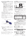
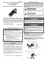
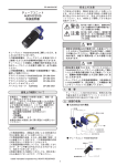
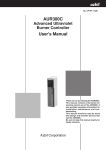
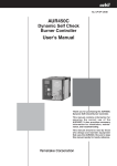
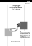
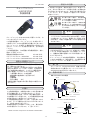
CP-UM-5347 安全上の注意 この安全上の注意は、製品を安全に正しくお使いいた だき、あなたや他の人々への危害や財産への損害を未 然に防止するためのものです。安全上の注意は必ず守 ってください。また、内容をよく理解してから本文を お読みください。 チューブユニット AUD10C2100 取扱説明書 警告 注意 取り扱いを誤った場合に、使用者が死 亡または重傷を負う危険の状態が生じ ることが想定される場合。 取り扱いを誤った場合に、使用者が軽 傷を負うか、または物的損害のみが発 生する危険の状態が生じることが想定 される場合。 警告 ・ 燃焼安全制御器AURの電源を切った直後にアドバ ンストUVセンサAUD300CやAURのF端子、G端子 には触れないでください。電源を切った後も1分以 内はF端子、G端子に電荷が残っており感電する恐 れがあります。 チューブユニットAUD10C2100をご購入いただき、ま ことにありがとうございます。 この取扱説明書は、チューブユニットを安全に正しく ご使用いただくための必要事項が記載されております。 チューブユニットを使用した機器の保守を担当される 方がチューブユニットを交換する際には、必ずお読み ください。 この取扱説明書は、次の関連する取扱説明書と一緒に、 保存しご活用ください。 燃焼安全制御器AUR300C CP-UM-5275 アドバンストUVリレーAUR350C CP-UM-5318 アドバンストUVセンサAUD300C2100 CP-UM-5344 注意 ・燃焼装置を運搬するときは、アドバンストUVセン サAUD300Cやチューブユニットは取り外して購入 したときの専用の梱包箱に入れて輸送してくださ い。運搬時の衝撃や振動により正常に動作しなくな ることがあります。 ・チューブユニットの有効使用期限は、3年未満ある いは25,000時間です。安全対策上、この期限内に新 しいチューブユニットと交換してください。 使用上の制限について 1. 概 要 本製品は、一般機器での使用を前提に、開発・設 計・製造されております。 とくに、下記のような安全性が必要とされる用途に 使用する場合は、フェールセーフ設計、冗長設計 お よび 定期点検の実施など、システム・機器全体の 安全に配慮していただいた上でご使用ください。 ・人体保護を目的とした安全装置 ・輸送機器の直接制御(走行停止など) ・航空機 ・宇宙機器 ・原子力機器 など 本製品の働きが直接人命に関る用途には使用しない でください。 チューブユニットAUD10C2100は、燃焼火炎の紫 外線を検出する光電管でアドバンストUVセンサ AUD300C2100に組み付けて使います。 2. 各部の名称 ● AUD300C2100の構成 取付部 フランジユニット カバー取付ねじ(4本) お願い リード線 この取扱説明書は、本製品をお使いになる担当者のお 手元に確実に届くようにお取りはからいください。 この取扱説明書の全部、または一部を無断で複写、ま たは転載することを禁じます。この取扱説明書の内容 を将来予告なしに変更することがあります。 この取扱説明書の内容については、万全を期しており ますが、万一ご不審な点や記入もれなどがありました ら、当社までお申し出ください。 お客様が運用された結果につきましては、責任を負い かねる場合がございますので、ご了承ください。 カバー 81446925-002 シャッタユニット AUD50A2100 チューブユニット AUD10C2100 ● チューブユニットAUD10C2100 固定ねじ サーモラベル ラベル 固定ねじ 2005 Yamatake Corporation ALL RIGHTS RESERVED 紫外線受光部 J1 ハウジング 3. チューブユニットの交換 4. 動作確認 取扱い上の注意 ・交換作業の際には、チューブユニットに衝撃 を与えないように、ていねいに取り扱ってく ださい。 ・持ち運びや保管するときは、必ず購入したと きの専用の梱包箱に入れてください。 ・アドバンストUVセンサAUD300C2100の使用 温度範囲の上限は100℃です。高温で使用す る場合やチューブユニットのサーモラベルの 120℃の部分が黒くなっている場合は、周囲 温度を確認しエアパージなどで冷却してくだ さい。 ・交換作業が終わってカバ−を取り付けると き、フランジユニットのOリングは確実に取 り付けてください。シール性が保てなくなり ます。 ・端子ねじや取付ねじは、締付トルク0.7N・m で締め付けてください。 AURのフレーム電圧出力端子でチューブユニットの動 作を確認します。 5 2.5 0 A μ 15 FSP136A100 または相当品 0 V 7.5 μA・V AUR出力端子 TAUT BAND レコーダ 15UA SPL OFF DC 0∼7.5Vレンジ 入力インピーダンス 100kΩ以上 7.5V 7.5V − + 黒 赤 ① AURのフレーム電圧出力端子にFSP136A100または 相当品を接続してください。 ② AUD300C2100の紫外線受光部の直前でライターなどを 点火し、フレーム電圧が出ることを確認してください。 取扱い上の注意 ・火気使用時は、周囲に可燃ガスがないことを 確認してください。 ① 燃焼安全制御器AURの電源を切ってください。 ② 1分以上経過してから取付ナットを緩めて、アドバン ストUVセンサAUD300C2100を監視パイプから取り 外してください。 ③ 監視パイプにAUD300C2100を取り付けてください。 ④ バーナを燃焼させてください。 ⑤ FSP136A100または相当品でAURのフレーム電圧出 力端子間のフレーム電圧出力を測定してください。 ③ AUD300C2100のカバー取付ねじ4本を外し、カバー を取り外してください。 推奨フレーム電圧 DC2.0V以上(フレームレスポンス1.5s)安 定していること DC1.5V以上(フレームレスポンス3s) 安 定していること (本器のシャッタ動作に同期して、0.1∼ 0.3Vの範囲でフレーム電圧が変動します) ④ チューブユニット後部のチューブユニット固定ねじ2 本を外してください。 ⑤ チューブユニット後部を持ち、静かに上方に持ち上 げて取り外してください。 取付部 10 5 チューブユニット 点検項目 炎の監視が正しいか 本器の受光部レンズ が汚れていないか 監視パイプにすすな どが詰まっていない か 取扱い上の注意 ・フレーム電圧が4Vを超えるようなときはオリ フィスを入れて紫外線の量を制限してくださ い。紫外線の量が多すぎるとシャッタが閉じ たときでも乱反射による紫外線がチューブユ ニットに入り誤動作する恐れがあります。 サーモラベル フランジユニット 5. 点検・調整 ケーブルガイド チューブユニット固定ねじ(2か所) チューブユニットを交換したときは、チューブユニッ トの機能をチェックするために、パイロットターンダ ウンテスト、点火スパーク応答テスト、安全遮断テス トは確実に行ってください。 カバー取付ねじ (4か所) それぞれのテストの詳細は ⑥ 新しいチューブユニットの先端をシャッタユニット 上部の丸穴に差し込み、後部を押し下げるようにし て取り付けます。 AUR300C 取扱説明書 CP-UM-5275 AUR350C 取扱説明書 CP-UM-5318 をご覧ください。 取扱い上の注意 〔ご注意〕この資料の記載内容は、お断りなく変更する場合もありますので ご了承ください。 ・チューブユニットには極性があります。取り 付けてあるシャッタユニットAUD50Aの上部 の極性表示ラベルF、Gにあわせて正しく取 り付けてください。 アドバンスオートメーションカンパニー 本 社 〒100-6419 東京都千代田区丸の内2-7-3 東京ビル 北海道支店 (011)781-5396 中部支社 (052)238-3037 東北支店 (022)292-2004 関西支社 (06)6881-3383∼4 北関東支店 (048)653-8733 中国支店 (082)222-3982 東京支社 (03)6810-1200 九州支社 (093)952-1210 ⑦ チューブユニット固定ねじ2本を締め付けてください。 ⑧ Oリングがフランジユニットから外れていないか確 認してください。 製品のお問い合わせ、計装のご相談は… コールセンター: ⑨ カバーをカバー取付ねじ4本で固定してください。 0466-20-2143 〈COMPO CLUBアドレス〉 http://www.compoclub.com 〈山武ホームページアドレス〉 http://jp.azbil.com この資料は再生紙を使用しています。 J2 (13) 2005年 3月 初版発行(E) 2006年 11月 改訂3版(U) CP-UM-5347E SAFETY PRECAUTIONS Tube unit AUD10C2100 User's Manual Safety precautions are for ensuring safe and correct use of this product, and for preventing injury to the operator and other people or damage to property. You must observe these safety precautions. Also, be sure to read and understand the contents of this user's manual. WARNING Warnings are indicated when mishandling this product might result in death or serious injury to the user. CAUTION Cautions are indicated when mishandling this product might result in minor injury to the user, or only physical damage to this product. Thank you for purchasing the AUD10C2100. This manual contains information for ensuring correct use of the AUD10C.This manual should be read by any personnel who are responsible for the maintenance of devices that are installed with the tube unit. Keep this manual in an easily accessible place with the following related manuals: Advanced UV relay AUR300C WARNING • Do not touch this unit or the F-terminal or G-terminal of the AUR immediately after the power to the AUR has been turned OFF. The F-terminal and G-terminal are still electrically alive within 1 min after the power has been turned OFF, causing an electric shock hazard. CAUTION CP-SP-1142E • When transporting combustion equipment, uninstall the AUD300C Advanced UV Sensor and the tube unit, and ship them in the same packaging that they were in when they were received. Failure to do so could result in faulty operation incurred from shock or vibration during shipping. • The service life of the AUD10C tube unit built-into this unit is 3 years or 25,000 operation hours. To ensure the operational safety, replace the tube unit with a new one within this service life. RESTRICTIONS ON USE This product has been designed, developed and manufactured for general-purpose application in machinery and equipment. Accordingly, when used in applications outlined below, special care should be taken to implement a fail-safe and/or redundant design concept as well as a periodic maintenance program. • Safety devices for plant worker protection • Start/stop control devices for transportation and material handling machines • Aeronautical/aerospace machines • Control devices for nuclear reactors Never use this product in applications where human safety may be put at risk. 1.Overview The AUD10C2100 tube unit is a photoelectric cell to detect the ultraviolet rays of the burner flame, and is used in combination with the AUD300C2100 advanced UV sensor. 2.Names of parts ● Construction of AUD300C2100 Mounting nut Flange unit Cover mounting screw (4 pcs) REQUEST Make sure that this User's Manual is handed over to the user before the product is used. Copying or duplicating this User's Manual in part or in whole is forbidden. The information and specifications in this User's Manual are subject to change without notice. Considerable effort has been made to ensure that this User's Manual is free from inaccuracies and omissions. If you should find any inaccuracies or omissions, please contact Yamatake Corporation. In no event is Yamatake Corporation liable to anyone for any indirect, special or consequential damages as a result of using this product. Lead wire Cover 81446925-002 Shutter unit AUD50A2100 Tube unit AUD10C2100 ● Tube unit AUD10C2100 Tube unit fixing screw Thermo-label 2004 Yamatake Corporation ALL RIGHTS RESERVED Ultraviolet ray receiving part E1 Label Tube unit fixing screw Housing 3.Replacement of tube unit 4.Operation check Handling Precautions • When replacing the shutter unit, be careful not to impact or otherwise damage the shutter unit. When verifying the function of the tube unit, use the flame-voltage output terminals of the AUR. FSP136A100 or equivalent • When transporting or storing the AUD10C, be sure to package it in the same packaging that it was in when it was received. TAUT BAND AUR OUTPUT Recorder 15UA SPL OFF + 0 to 7.5Vdc range Input impedance: 100 kΩ or more Black Red (1) Connect the FSP136A100 to flame voltage output terminals of the AUR. (2) To make sure that flame-voltage output is being generated, light a cigarette lighter in front of the ultraviolet ray detector of the AUD300C2100. • Tighten the terminal screws and mounting screws with a tightening torque of 0.7N•m. (1) Turn OFF the power to the AUR. (2) Loosen the mounting nut after at least one minute has passed, then remove the AUD300C2100 Advanced UV Sensor from the monitoring pipe. (3) Remove the cover by unscrewing the four (4) mounting screws that secure it to the AUD300C2100. Handling Precautions •When using an open flame, check that there is no flammable gas near this unit. (3) Mount the AUD300C2100 on the monitoring pipe. (4) Start the combustion of the burner. (5) Measure the flame voltage between flame voltage output terminals of the AUR with the FSP136A100. (4) Remove 2 tube unit fixing screws on the rear of the tube unit. (5) Hold the rear of the tube unit and gently raise it upward to remove it. (6) Insert the top of a new tube unit into the round hole in the upper portion of the shutter unit and push-down the rear to mount it. Mounting nut 7.5V 7.5V • The upper limit of the operating temperature range of this unit is 100˚C. If the 120˚C-part of the thermo label of the AUD10C tube unit becomes black, check the ambient temperature and cool the unit using the air purging. Recommended flame voltage Inspection item • The flame is monitored correctly. • The light-receiving lens of this unit is not dirty. • No soot or other foreign matter has accumulated in the monitoring pipe. Stable 2.0Vdc or more (flame response 1.5s) Stable 1.5Vdc or more (flame response 3s) (The flame voltage may fluctuate in a range of 0.1 to 0.3V synchronized with the shutter operation of this unit.) Tube unit Thermo-label Handling Precautions •When the flame voltage exceeds 4Vdc, decrease the ultraviolet rays in quantity by orifice. A large quantities of ultraviolet rays might cause malfunction. Flange unit Cable guide Tube unit fixing screw (2 pcs) Cover mounting screw (4 pcs) 5.Inspection and adjustment After replacing the tube unit, perform a pilot turndown test, an ignition spark response test and a safety shutoff test to verify proper functioning of the tube unit. Handling Precautions •The tube unit has specific polarities. Make these polarities matched with the polarity indication label F, G at the upper portion of the shutter unit and mount it correctly. For the details on each test, refer to the Advanced UV reray AUR300C User's Manual (CP-SP-1142E). (7) Tighten 2 tube unit fixing screws. (8) Make sure that the O-ring is not disengaged from the flange unit. (9) Secure the cover with 4 cover mounting screws. Specifications are subject to change without notice. Advanced Automation Company 1-12-2 Kawana, Fujisawa Kanagawa 251-8522 Japan Printed in Japan. 1st Edition: Issued in Mar. 2005 (E) 3rd Edition: Issued in Nov. 2006 (U) URL: http://www.azbil.com E2 Printed on recycled paper. (07)