1
No. CP-SP-1170E
AUD300C2100
Advanced UV Sensor
User's Manual
Thank you for purchasing the AUD300C
2100.
This manual contains information for
ensuring correct use of the AUD300C
2100. It also provides necessary information for installation, maintenance,
and troubleshooting.
This manual should be read by those
who design and maintain devices that
use the AUD300C2100.
Be sure to keep this manual nearby for
handy reference.
RESTRICTIONS ON USE
This product has been designed, developed and manufactured for general-purpose
application in machinery and equipment. Accordingly, when used in the applications
outlined below, special care should be taken to implement a fail-safe and/or redundant
design concept as well as a periodic maintenance program.
• Safety devices for plant worker protection
• Start/stop control devices for transportation and material handling machines
• Aeronautical/aerospace machines
• Control devices for nuclear reactors
Never use this product in applications where human safety may be put at risk.
REQUEST
Ensure that this User's Manual is handed over to the user before the
product is used.
Copying or duplicating this User's Manual in part or in whole is forbidden. The information and specifications in this User's Manual are subject to change without notice.
Considerable effort has been made to ensure that this User's Manual is
free from inaccuracies and omissions.
If you should find any inaccuracies or omissions, please contact
Yamatake Corporation.
In no event is Yamatake Corporation liable to anyone for any indirect,
special or consequential damages as a result of using this product.
©2004 Yamatake Corporation ALL RIGHTS RESERVED
SAFETY PRECAUTIONS
■ About Icons
The safety precautions described in this manual are indicated by various icons.
Please be sure you read and understand the icons and their meanings described
below before reading the rest of the manual.
Safety precautions are intended to ensure the safe and correct use of this product, to prevent injury to the operator and others, and to prevent damage to property. Be sure to observe these safety precautions.
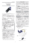
WARNING
Warnings are indicated when mishandling this
product might result in death or serious injury.
CAUTION
Cautions are indicated when mishandling this
product might result in minor injury to the user, or
only physical damage to the product.
■ Examples
Use caution when handling the product.
The indicated action is prohibited.
Be sure to follow the indicated instructions.
i
WARNING
Do not combine the AUD300C with a unit other than Yamatake's flame
safeguard control AUR series.
Do not use this unit for detection of ultraviolet rays other that those of the
burner flame. If this unit responds to other ultraviolet rays, the status that the
flame failure occurs in the burner is determined as flame presence. Thus,
the fuel flows out continuously, causing an explosion.
Before removing or mounting the AUD300C, be sure to turn the power OFF.
Failure to do so might cause electric shock.
Before wiring the AUD300C, be sure to turn the power OFF. Failure to do so
might cause electric shock
To prevent an explosion trouble, carry out the pilot turndown test firmly. If the
AUD300C detects a small pilot flame, which cannot ignite the main burner, it
is determined that flame failure does not occur in the flame safeguard control
even though the flame failure occurs in the main burner. Thus, the fuel is
supplied continuously, causing an exposition accident, resulting in a serious
hazard.
When performing the pilot turndown test repeatedly, stop the equipment
completely every time the pilot turndown test is completed in order to
completely discharge the unburnt gas or oil accumulated in the combustion
chamber or flue.
If the unburnt gas or oil is not discharged completely, this might cause an
explosion accident.
Do not touch terminals F or G on the AUD300C or on the AUR immediately
after the power to the AUR has been turned OFF.
The F-terminal and G-terminal are still electrically alive within 1min after the
power has been turned OFF, causing an electric shock hazard.
When measuring the voltage between the F-terminal and G-terminal of the
AUD300C in the wiring check, do not touch any terminal by bare hand.
Doing so might cause an electric shock.
ii
CAUTION
The AUD300C is specially designed for intermittent burner operation (system
is started and stopped once or more within 24 hours.) and continuous burner
operation (system continues the combustion for 24 hours or longer).
The AUR series having the self-check function must be used as an amplifier
to be combined.
Only authorized personnel who have the technical skill about the combustion
equipment and flame safeguard control must carry out the mounting, wiring,
inspection, adjustment, and maintenance work.
If the AUD300C is operated in an atmosphere where any steam, smoke, oil
mist, dust, and/or organic solvent exist that hinder the penetration of
ultraviolet rays, take appropriate corrective measures.
When using multiple burners, mount the AUD300C at a position where it
detects the flame of only the burner to be monitored.
Carry out the wiring work in conformity with the specified standards.
Always separate the signal cables of the AUD300C from the high voltage
cables of the ignition transformer and power cables, and then always run the
signal cables in a different conduit tube.
After the wiring work has been completed, always check that the wiring is
correct. Incorrect wiring may cause damage or malfunction.
Only authorized personnel who have the technical skill about the combustion
equipment and flame safeguard control must carry out the pilot turndown
test.
The service life of the tube unit AUD10C built-into the AUD300C is 3 years or
25,000 operation hours.
To ensure the operational safety, replace the tube unit with a new one within
this service life.
Do not transport the AUD300C with it mounted on the combustion
equipment. The impact or vibration during transportation may cause the
AUD300C to malfunction.
Before starting the transportation, remove the AUD300C and put it in the
specially designed packing box.
Replace the shutter unit AUD50A with a new one at a reference replacement
interval of 3 years.
iii
The Role of This Manual
There are nine manuals have been prepared for the AUD300C, AUR series. Read the manual according to your
specific requirements. The following lists all the manuals that accompany the AUD300C, AUR series and gives a
brief outline of the manual: If you do not have the required manual, contact Yamatake Corporation or your dealer.
AUD300C2100 Advanced UV Sensor
Manual No.CP-SP-1170E
This manual
The manual describes the mounting, wiring, maintenance and inspection,
and troubleshooting when the AUD300C is built-into the combustion
equipment.
AUR300C Advanced UV Relay
Manual No.CP-SP-1142E
The personnel in charge of design, mounting, operation, and maintenance
of the combustion equipment using the AUR300C must read this manual.
The manual describes the mounting, wiring, trial-run adjustment, and
maintenance and inspection of the AUR300C.
AUR350C Advanced UV Relay with Communications
Manual No.CP-SP-1175E
Personnel in charge of design, mounting, operation, and maintenance of
combustion equipment using the AUR350C should read this manual.
It describes the mounting, wiring, trial-run adjustment, maintenance,
inspection of the AUR350C.
AUR450C Dynamic Self Check Burner Controller
Manual No. CP- SP-1264E
This manual should be read by personnel using the AUR450C for the first
time, those in charge of designing combustion equipment that uses the
AUR450C or designing the hardware for mounting the device in a control
panel, and personnel performing maintenance.
The manual gives an overview of the product, its mounting and wiring for
connection to other equipment, its operation, trial-run adjustment, maintenance and inspection, and specifications.
123E
C P-UM-0
nual
User's Ma
WARNING
CAUTION
WARNING
CAUTION
123E
C P-UM-0
nual
User's Ma
FSP300C Flame Simulator
Manual No. CP-SP-1209E
It should be read in advance by those who use the FSP300C to check the
operation of the AUD300C/500C and the AUR300C/350C/400C/450C. This
manual describes installation, operation, and precautions for use of the
FSP300C.
FSP350A Checker for AUR300C/350C
Manual No. CP-SP-1210E
WARNING
FSP450A Checker for AUR450C
Manual No. CP-SP-1211E
CAUTION
It should be read in advance by those who use the FSP350A to check the
operation of the AUR300C/350C, and those who use the FSP450A to
check the operation of the AUR450C. This manual gives important
information and precautions for use of the FSP350A and FSP450A.
WARNING
CAUTION
iv
123E
C P-UM-0
nual
User's Ma
WARNING
CAUTION
CAUTION
123E
C P-UM-0
nual
User's Ma
FSP136A Analog Flame Meter
Manual No. CP-SP-1212E
WARNING
It should be read in advance by those who use the FSP136A to check the
voltage of the AUR300C/350C/400C/450C. This manual gives important
information and precautions for use of the meter.
WARNING
CAUTION
AUD60A2100 Maintenance Kit for AUD
Manual No. CP-UM-5441E
CAUTION
This manual describes a way of change the maintenance kit for the
AUD300C2100, that is composed of the tube unit, the shutter unit and the Oring etc. as consumables.
WARNING
Conventions Used in This Manual
The following conventions are used in this manual:
Handling Precaution
: Handling Precautions indicate items that the user should pay attention to
when handling the AUD300C.
: This indicates the item or page that the user is requested to refer to.
(1), (2), (3)
: The numbers with the parenthesis indicate steps in a sequence or
indicate corresponding parts in an explanation.
>>
: Indicates the result of operation or the state of the device after operation.
v
Contents
SAFETY PRECAUTIONS
The Role of This Manual
Conventions Used in This Manual
Chapter 1.
OVERVIEW
■
■
■
■
■
Chapter 2.
Overview • • • • • • • • • • • • • • • • • • • • • • • • • • • • • • • • • • • • • • • • • • • • • • • • • • • • • • • • • • • • • • • • • 1
Features • • • • • • • • • • • • • • • • • • • • • • • • • • • • • • • • • • • • • • • • • • • • • • • • • • • • • • • • • • • • • • • • • 1
Part names • • • • • • • • • • • • • • • • • • • • • • • • • • • • • • • • • • • • • • • • • • • • • • • • • • • • • • • • • • • • • • • 1
Model No. • • • • • • • • • • • • • • • • • • • • • • • • • • • • • • • • • • • • • • • • • • • • • • • • • • • • • • • • • • • • • • • • 2
Configuration • • • • • • • • • • • • • • • • • • • • • • • • • • • • • • • • • • • • • • • • • • • • • • • • • • • • • • • • • • • • 2
MOUNTING
■
■
■
■
■
■
Chapter 3.
Before mounting this unit • • • • • • • • • • • • • • • • • • • • • • • • • • • • • • • • • • • • • • • • • • • • • • • • 3
Monitoring of burner flame• • • • • • • • • • • • • • • • • • • • • • • • • • • • • • • • • • • • • • • • • • • • • • • 3
Mounting position• • • • • • • • • • • • • • • • • • • • • • • • • • • • • • • • • • • • • • • • • • • • • • • • • • • • • • • • 4
Mounting posture • • • • • • • • • • • • • • • • • • • • • • • • • • • • • • • • • • • • • • • • • • • • • • • • • • • • • • • • 5
Mounting of monitoring pipe • • • • • • • • • • • • • • • • • • • • • • • • • • • • • • • • • • • • • • • • • • • • • 6
Mounting procedure • • • • • • • • • • • • • • • • • • • • • • • • • • • • • • • • • • • • • • • • • • • • • • • • • • • • • 8
WIRING
■ Wiring diagram• • • • • • • • • • • • • • • • • • • • • • • • • • • • • • • • • • • • • • • • • • • • • • • • • • • • • • • • • • • 9
■ Checking of wiring • • • • • • • • • • • • • • • • • • • • • • • • • • • • • • • • • • • • • • • • • • • • • • • • • • • • • • 10
Chapter 4.
ADJUSTMENT
■
■
■
■
■
■
Before measurement of flame voltage • • • • • • • • • • • • • • • • • • • • • • • • • • • • • • • • • • 11
Measurement of flame voltage • • • • • • • • • • • • • • • • • • • • • • • • • • • • • • • • • • • • • • • • • • 11
Pilot turndown test • • • • • • • • • • • • • • • • • • • • • • • • • • • • • • • • • • • • • • • • • • • • • • • • • • • • • 12
Ignition spark response test • • • • • • • • • • • • • • • • • • • • • • • • • • • • • • • • • • • • • • • • • • • • 13
Firmly mounting of monitoring pipe • • • • • • • • • • • • • • • • • • • • • • • • • • • • • • • • • • • • 13
Final inspection • • • • • • • • • • • • • • • • • • • • • • • • • • • • • • • • • • • • • • • • • • • • • • • • • • • • • • • • • 13
Chapter 5.
TROUBLESHOOTING
Chapter 6.
MAINTENANCE AND INSPECTION
■
■
■
■
Chapter 7.
Periodic inspection • • • • • • • • • • • • • • • • • • • • • • • • • • • • • • • • • • • • • • • • • • • • • • • • • • • • • 15
Replacement of maintenance kit • • • • • • • • • • • • • • • • • • • • • • • • • • • • • • • • • • • • • • • • 16
Replacement of tube unit • • • • • • • • • • • • • • • • • • • • • • • • • • • • • • • • • • • • • • • • • • • • • • • 16
Replacement of shutter unit • • • • • • • • • • • • • • • • • • • • • • • • • • • • • • • • • • • • • • • • • • • • 17
SPECIFICATION
■ Specification • • • • • • • • • • • • • • • • • • • • • • • • • • • • • • • • • • • • • • • • • • • • • • • • • • • • • • • • • • • • 19
■ Dimensions • • • • • • • • • • • • • • • • • • • • • • • • • • • • • • • • • • • • • • • • • • • • • • • • • • • • • • • • • • • • • 20
vi
Chapter 1.
OVERVIEW
■ Overview
This advanced ultraviolet sensor AUD300C2100 (hereafter referred to as the
AUD300C) is a flame detector designed to sense the ultraviolet ray radiation of
the oil or gas burner flame. This unit is used in combination with the dedicated
Advanced Ultraviolet Relay (hereafter referred to as AUR series). Any
malfunction that has occurred in the AUD300C or AUR series can be detected by
the accurate dynamic continuous self-check function of the built-in shutter driven
by the AUR series, ensuring highly reliable combustion safety control.
■ Features
• Maintenance parts such as the tube unit AUD10C and shutter unit AUD50A
can be handled as a single unit. This ensures easy replacement and
maintenance work.
• As for a flame sensor for the self-check, the AUD300C is compact and
lightweight. This ensures free burner mounting.
• The operating ambient temperature is 100°C and the protection structure is
IP66. This ensures excellent environment-proof performance.
• The vertical mounting is possible and the maximum wiring distance is 200 m.
This ensures flexible construction work.
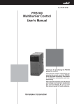
■ Part names
● Main unit
● Tube unit AUD10C2100
Mounting nut
Flange unit
Fixing screw
Thermo-label
Ultraviolet ray
receiving part
Lead wires
Cover 81446925-002
Label
Fixing screw
Housing
Shutter unit AUD50A2100
Tube unit AUD10C2100
● Shutter Unit AUD50A2100
Shutter unit
G-terminal (yellow lead wire)
F-terminal (blue lead wire)
Shutter driving terminal (white lead wire)
1
Chapter 1. Overview
■ Model No.
Model No.
AUD300C2100
AUD300C210D
AUD300C210DT
Description
Advanced UV Sensor
Advanced UV Sensor with inspection certificate
Advanced UV Sensor with inspection certificate and
tropicalization treatment applied
● Applicable standards
UL certificated; UL file No.MH27717
■ Configuration
● Combined combustion safety controller
• AUR300C/350C
Series
Basic
Function
Flame
Power
Option
Model No.
response supply voltage
AUR
Contents
Advanced UV relay
300C
350C
1
2
3
1
2
00
D0
T0
DT
With communication function
Fixed
Flame response 1.5s(nominal value)
Flame response 3.0s(nominal value)
100Vac
200Vac
Without option
Inspection certificate provided
Tropicalization treatment applied
Tropicalization treatment applied and
inspection certification provided
• AUR450C
Basic Safety Standard Flame failure Power
AddAddDescription
model No. time compliance response time supply processing1 processing2
AUR450C
4
8
2
2
3
1
2
3
5
0
00
D0
T0
DT
Dynamic self check burner controller
4±1 s
8±2 s
With standard compliance
1.5 s maximum (2 s maximum)
3 s maximum (4 s maximum)
100 Vac CE, UL standards
200 Vac CE standards
120 Vac CE, UL standards
230 Vac CE standards
No additional processing
Inspection certification provided
Tropicalization treatment applied
Tropicalization treatment applied and
inspection certification provided
● Maintenance parts and Optional parts
Description
2
Maintenance kit
Tube unit
Shutter unit
Cover
Bushing 1 X 3/4
Analog flame meter
Model No.
AUD60A2100
AUD10C2100
AUD50A2100
81446925-002
81409780-001
FSP136A100
Chapter 2.
MOUNTING
WARNING
Before removing or mounting the AUD300C, be sure to turn the power OFF.
Failure to do so might cause electric shock.
Do not use the AUD300C for detection of ultraviolet rays other that those of
the burner flame. If the AUD300C responds to other ultraviolet rays, the
status that the flame failure occurs in the burner is determined as flame
presence. Thus, the fuel flows out continuously, causing an explosion.
CAUTION
Only authorized personnel who have the technical skill about the combustion
equipment and flame safeguard control must carry out the mounting, wiring,
inspection, adjustment, and maintenance work.
If the AUD300C is operated in an atmosphere where any steam, smoke, oil
mist, dust, and/or organic solvent exist that hinder the penetration of
ultraviolet rays, take appropriate corrective measures.
When using multiple burners, mount the AUD300C at a position where it
detects the flame of only the burner to be monitored.
■ Before mounting this unit
• To mount the AUD300C correctly, thoroughly read the instruction manuals
published by burner, boiler, and/or other equipment manufacturers. Make the
proper mounting plan while referring to such instruction manuals.
• It is necessary that the AUD300C actually monitors the flame. As long as the
overall layout and temperature around the burner and other limitations permit,
mount the AUD300C as close to the flame as possible. As the AUD300C is
mounted closer to the burner nozzle, the detection amount of the ultraviolet ray
radiation will increase.
• Mount the AUD300C at a position far from the ignition transformer.
Additionally, mount the ignition transformer as close to the burner as possible,
and then ground it firmly.
■ Monitoring of burner flame
● Monitoring of only pilot flame (Continuous pilot, intermittent pilot)
The main burner must be ignited firmly with the minimum pilot flame that the
AUD300C can detect. Therefore, throttle the pilot fuel manual valve until the
main burner is ignited barely. Mount the AUD300C under these conditions so
that the unit monitors only the top of the pilot flame. Put the monitoring area as
close to the top of the flame as possible so that the unit monitors the pilot flame
along with the axis of the pilot flame.
● Monitoring of both pilot flame and main flame (Continuous pilot, intermittent pilot)
Mount the AUD300C so that the unit monitors an area where the pilot flame
intersects the main flame.
3
Chapter 2. MOUNTING
● Monitoring of only main flame (Interrupted pilot)
Mount the AUD300C so that the unit monitors any status of the main flame (most
stable part of the flame in both the low-combustion and high-combustion).
In the special combustion, it is recommended to use two units in order to monitor
the main flame of each of the high-combustion and low-combustion.
● Monitoring of pilot flame and main flame individually (continuous pilot or intermittent pilot)
Mount the AUD300C so that the sensor for monitoring the main flame does not
mistakenly detect the pilot flame. If the sensor for the main flame detects the pilot
flame, the fuel supply will not be shut down if the main burner fails, since the
flame failure will not be detectable.
● Multiple burners existing in one combustion chamber
Mount the AUD300C on each burner and carry out the mounting work so that the
unit does not detect the flame of other burner incorrectly.
Additionally, the tube unit AUD10C of the AUD300C may produce the electrical
discharge phenomenon inside the tube. This electrical discharge may emit the
ultraviolet rays from the tube. Therefore, when using multiple units, adjust their
positions so that the ultraviolet ray radiation from other tube unit is not detected.
● Redundant system (Duplicate monitoring)
To increase the reliability of the system and avoid unnecessary shut-off as much as
possible, the AUD300C is combined with the AUR series and the redundant
system is constructed so that two sets monitor the flame of one burner.
If two AUR series units detect the flame failure at the same time, the system must
be shut-off. If either flame detector does not output the flame signal or if any
dummy signal exists, the alarm is given, but the system continues the combustion.
This avoids any unnecessary shut-off of the system caused by this unit,
combustion safety control unit, or oscillating flame. The highly reliable flame
monitor can be achieved.
■ Mounting position
Determine an optimal mounting position of the AUD300C while carefully
observing the following items:
● Temperature
Mount this unit in a place where the operating temperature range is -20°C to
+100°C.
Handling Precautions
• If the above temperature range is not observed, this may cause the
tube unit AUD10C or shutter unit AUD50A assembled to the
AUD300C to malfunction or unnecessary shut-off.
• If the actual temperature may exceed the operating temperature
range, put an appropriate thermal insulation plate between the
combustion chamber and the AUD300C or carry out the air purging to
put the temperature within the operating temperature range.
4
Chapter 2. MOUNTING
● Vibration
Mount the AUD300C in a place where the acceleration is 4.9 m/s2 or less.
Handling Precautions
• The vibration may cause the service life of the tube unit AUD10C or
shutter unit AUD50A to be shortened, improper operation, or
malfunction.
● Outdoor
Mount appropriate roofs or eaves to avoid rain water.
Handling Precautions
• There might be a case that the body color of the AUD300C is
changed by the influence of sunlight or other causes. But, there is no
problem for the product functions or operations.
■ Mounting posture
The allowable range of the mounting posture is that the upper limit is 90° (conduit
tube port becomes horizontal) and the lower limit is 45°.
Upper limit 90°
90°
Horizontal
plane
45°
Vertical
plane
Lower limit 45°
Side
Handling Precautions
• Mount this unit at an appropriate angle so that it monitors the burner
from the upper slanted position. If this unit is mounted so that it
monitors the burner from the lower slanted position or horizontal
position, dust or soot may accumulate on the monitoring window or in
the monitoring pipe. This may block the ultraviolet rays, causing the
flame not to be detected.
5
Chapter 2. MOUNTING
■ Mounting of monitoring pipe
● Materials of monitoring pipe
Use a monitoring pipe with the black inside wall. If a pipe with the stainless steel
or galvanized inside wall is used, the diffused reflection of the ultraviolet rays
occurs inside the pipe, causing a malfunction.
● Size of monitoring pipe
To detect the ultraviolet rays radiation of the flame at its optimal level, it is
necessary to widen the light receiving area of the AUD300C. If a recommended
flame voltage of 1.5V or more cannot be kept, make the monitoring pipe thicker to
receive a sufficient amount of ultraviolet rays.
• Use the monitoring pipe as thick as possible and connect the pipe to this unit
with the reducing socket.
• Make the length of the monitoring pipe as short as possible. However, always
keep the operating ambient temperature within 100°C.
● Mounting space
Keep a sufficient space to allow easy maintenance and inspection, and service
work.
$
("
)"
"
!
!
"
#"
$ %& !
" "
' !
"
Handling Precautions
• Mount this unit so that its monitoring direction intersects the flame
axis at an as small angle as possible. This ensures a wide
intersection area of the monitoring area between the flame and this
unit. Thus, the detection amount of ultraviolet ray radiation becomes
large.
6
Chapter 2. MOUNTING
Good
Depth of flame is long when the monitoring direction
intersects the flame axis at acute angle
Unburnt fuel
Burner
Bad
Depth of flame is short
● Temporary welding for positioning of monitoring pipe
(1) Prepare the monitoring pipe and make the mounting hole.
Make the mounting hole for the monitoring pipe at the selected monitoring
pipe mounting position.
Perform the screw threading of one end of the monitoring pipe and cut the
monitoring pipe to a desired length so that its length is as short as possible.
(2) Weld the monitoring pipe temporarily.
Weld the monitoring pipe temporarily to the plate of the combustion chamber,
such as boiler.
At this time, do not weld the monitoring pipe completely since the inspection
and adjustment are required until the flame is detected properly.
Monitoring pipe
Weld these parts temporarily.
Furnace wall
(Refractory material)
Plate
(3) Carry out the air purging of the monitoring pipe.
The air purging of the inside of the monitoring pipe is useful to cool the
AUD300C and keep the monitoring area clean.
In particular, if the ambient temperature of the AUD300C exceeds 100°C, the
cooling, such as air purging is needed.
• If the inside of the furnace is a type of induced draft, make an air purging
hole in the monitoring pipe.
• If the forced type furnace is used, connect an air purging supply pipe.
7
Chapter 2. MOUNTING
■ Mounting procedure
When mounting the AUD300C on a monitoring pipe, proceed as follows:
● Check item
File the monitoring pipe in advance to eliminate burrs and protrusions.
● Mounting
(1) Hold the unit securely with one hand to prevent it from rotating.
(2) Tighten the mounting nut approximately 4 turns with the other hand until the
unit is held securely in place.
(3) Make sure the unit is properly aligned in the vertical plane when viewed from
the front.
Do not tilt
Mounting pipe
Mounting nut
Vertical plane mounting
Do not mount
horizontally
Front side
Do not
mount upside-down
Handling Precautions
• Be sure the AUD300C is properly aligned vertically when seen from
the front. If not, the shutter in the AUD50A shutter unit may be
damaged or malfunction.
If this unit is not mounted correctly, this may cause the shutter of the
shutter unit AUD50A to be damaged or malfunction.
• File any burrs or protrusions from the monitoring pipe. If the packing
in the mounting nut is damaged, any chance of leakage may be
caused.
• Do not use a tool such as pipe wrench when tightening the mounting
nut. Excessive torque by a tool could damage the packing and
compromise the seal.
• Do not adjust the mounting pose by forcibly holding the unit or wiring
pipe. Failure to do so may damage the packing and compromise the
seal.
8
Chapter 3.
WIRING
WARNING
Before wiring the AUD300C, be sure to turn the power OFF. Failure to do so
might cause electric shock
When measuring the voltage between the F-terminal and G-terminal of the
AUD300C in the wiring check, do not touch any terminal by bare hand.
Doing so might cause an electric shock.
CAUTION
Only authorized personnel who have the technical skill about the combustion
equipment and flame safeguard control must carry out the mounting, wiring,
inspection, adjustment, and maintenance work.
Always separate the signal cables of the AUD300C from the high voltage
cables of the ignition transformer and power cables, and then always run the
signal cables in a different conduit tube.
■ Wiring diagram
Advanced UV Sensor
AUD300C
White
Shutter output terminal
White
Yellow
Blue
(G)
(F)
When performing the wiring work, put all lead wires used for the connection with
the AUR series in the conduit tube or conduit box. Additionally, set these lead
wires separated from other power cables.
Handling Precautions
• Never set the lead wires to the AUD300C in the same conduit tube
containing the high voltage cables, such as power cables or ignition
transformer cables.
• Put the high voltage cables of the ignition transformer and the
grounding cables in the same conduit tube. At the same time, ground
one end of this conduit tube firmly. In particular, this caution must be
observed strictly when using an automotive spark plug.
• If the surge of the ignition transformer adversely affects the
AUD300C, ground both ends of the conduit tube between the
AUD300C and combustion safety control unit or change the cable
wiring route.
9
Chapter 3. WIRING
■ Checking of wiring
Before applying the voltage to this unit, check that the wiring is correct.
● Procedures
(1) Remove the cover of this unit and take out the tube unit AUD10C. For details
about how to take out the tube unit
refer to the section, Replacement of tube unit, in Chapter 6.
(2) Turn ON the power to the AUR300C.
(3) Measure the DC voltage between the F-terminal and G-terminal with a multimeter or digital voltmeter.
(4) Connect the positive probe to the G-terminal (yellow lead wire) and the
negative probe to the F-terminal (blue lead wire).
Positive probe
Negative probe
G-terminal
yellow lead wire
Terminal
Probe
F
-
G
+
Voltage
DC160 to 220V
F-terminal
blue lead wire
>> If a voltage of 160Vdc to 220Vdc is output, it is determined that the wiring
work has been performed correctly. If the measured DC voltage is a
negative value, the wiring to the F-terminal and G-terminal is connected
reversely.
(5) Next, measure the DC voltage between the shutter voltage S1-terminal and S2terminal (both are white lead wires).
Handling Precautions
The polarities of the S1-terminal and S2-terminal are not specified.
When measuring the voltage with an analog multi-meter, set a large
voltage range so that the indication needle does not deflect over the
negative scale to check the polarities. After that, measure the shutter
voltage.
>> If the indication needle swings in a range of 15Vdc to 24Vdc, it is
determined that the wiring is connected correctly.*
If the indication needle of the multi-meter shows 24Vdc constantly or if it
shows 0V, the wiring may be incorrect.
* If a flame exists, the shutter voltage swings within a range of 0Vdc to
24Vdc.
(6) Mount the tube unit AUD10C 1 min. or longer after the power to the
AUR300C has been turned OFF.
10
Chapter 4.
ADJUSTMENT
■ Before measurement of flame voltage
Before measuring the flame voltage, check the operation of this unit through the
flame voltage output terminals of the AUR300C.
Model No.
Flame voltage output terminals
AUR300C
AUR350C
Terminal 9 (+)
Terminal10 ( - )
AUR450C
Positive terminal, Negative terminal
(1) Connect a analog flame meter (FSP136A100) to the flame voltage output
terminals of the AUR300C.
(2) Light a lighter in front of the ultraviolet ray receiving part of this unit to check
that the voltage is output correctly.
Handling Precautions
• When using an open flame, check that there is no flammable gas around
this unit.
■ Measurement of flame voltage
If both pilot flame and main flame exist, measure each flame voltage.
Additionally, measure the flame voltage in the maximum combustion and
minimum combustion states.
(1) Mount the monitoring pipe on this unit temporarily.
(2) Start the combustion of the burner.
(3) To determine an optimal monitoring position, measure the flame voltage of the
AUR300C with the analog flame meter (FSP136A100) meter while moving
the monitoring pipe position little by little in order to find a position where as
highly stable voltage as possible is shown.
Recommended flame voltage
2.0 to 4.0Vdc (flame response 1.5s)
1.5 to 4.0Vdc (flame response 3s)
(The flame voltage may fluctuate in a
range of 0.1 to 0.3V synchronized with
the shutter operation of this unit.)
Inspection item
Check that the flame is monitored
correctly.
Check that the light receiving lens of
this unit is not contaminated.
Check that foreign matter, such as soot
is not caught in the monitoring pipe.
Handling Precautions
• When the flame voltage exceeds 4Vdc, provide an orifice sheet into the
flange unit to limit the quantity of ultraviolet rays. Excess quantity of
ultraviolet rays might cause malfunction by the diffused reflection of
ultraviolet rays coming into the tube unit even when the shutter is
closed.
11
Chapter 4. ADJUSTMENT
■ Pilot turndown test
This test is intended to check that the flame is correctly carried over to the main
burner when the AUD300C detects the pilot flame if the gas pressure and air
pressure are changed to their worst conditions.
WARNING
To prevent an explosion trouble, carry out the pilot turndown test firmly. If the
AUD300C detects a small pilot flame, which cannot ignite the main burner, it
is determined that flame failure does not occur in the flame safeguard control
even though the flame failure occurs in the main burner. Thus, the fuel is
supplied continuously, causing an exposition accident, resulting in a serious
hazard.
When performing the pilot turndown test repeatedly, stop the equipment
completely every time the pilot turndown test is completed in order to
completely discharge the unburnt gas or oil accumulated in the combustion
chamber or flue.
If the unburnt gas or oil is not discharged completely, this might cause an
explosion accident.
CAUTION
Only authorized personnel who have the technical skill about the combustion
equipment and flame safeguard control must carry out the mounting, wiring,
inspection, adjustment, and maintenance work.
Only authorized personnel who have the technical skill about the combustion
equipment and flame safeguard control must carry out the pilot turndown test.
For details about how to carry out the pilot turndown test, refer to the user's
manual for AUR series combined with the AUD300C, as well as the instruction
manuals published by equipment manufacturers.
12
Chapter 4. ADJUSTMENT
■ Ignition spark response test
WARNING
Do not use the AUD300C for detection of ultraviolet rays other that those of
the burner flame. If the AUD300C responds to other ultraviolet rays, the
status that the flame failure occurs in the burner is determined as flame
presence. Thus, the fuel flows out continuously, causing an explosion.
● Procedures
(1) Close the manual shut-off valves of the pilot burner and main burner.
(2) Operate the burner to perform the ignition operation. The ignition spark is then
started. At this time, check that the flame relay (K2) of the AUR300C is not
excited. (K2 is the flame relay for the AUR300/350, and K6 is the flame relay
for the AUR450.)
(3) If the flame relay is excited, adjust the monitoring point of this unit again to
avoid the influence of the ignition spark and its reflection.
Handling Precautions
• The table below shows various sources other than flame, that may
activate the AUD300C. Check that the AUD300C control action is not
influenced under all operating conditions.
Examples:
Ultraviolet ray
Scorching furnace wall with a temperature of 1370°C or more
sources
(within 50 cm of furnace wall)
Ignition transformer and welding arc spark (lightning)
Gas laser
Sunlamp
Disinfecting lamp, ultraviolet ray radiation lamp, fluorescent lamp
Strong flash light (toward UV sensor)
Gamma ray and Diffraction analyzer
X ray sources
Electron microscope
X ray camera
High voltage vacuum switch
High voltage capacitor
Radioactive isotope
Other sources producing ultraviolet rays, gamma rays, and X rays
■ Firmly mounting of monitoring pipe
(1) When the equipment is operated properly with the specified flame voltage
output after all adjustments have been completed correctly, turn OFF the power
to the equipment, remove the AUD300C, and weld the monitoring pipe firmly.
(2) Mount the AUD300C on the monitoring pipe firmly and perform the final
wiring completely.
■ Final inspection
To control the burner properly, perform at least one cycle operation of the
equipment to check that all control actions correctly.
13
Chapter 5.
TROUBLESHOOTING
WARNING
Before removing or mounting the AUD300C, be sure to turn the power OFF.
Failure to do so might cause electric shock.
Do not touch the AUD300C or the F-terminal or G-terminal of the AUR series
immediately after the power to the AUR series has been turned OFF.
The F-terminal and G-terminal are still electrically alive within 1min after the
power has been turned OFF, causing an electric shock hazard.
CAUTION
Only authorized personnel who have the technical skill about the combustion
equipment and flame safeguard control must carry out the mounting, wiring,
inspection, adjustment, and maintenance work.
● Tools and parts to be prepared
• Analog flame meter
FSP136A100
• For details about replacement parts, refer to the section;
● Maintenance parts and Optional parts (page 2).
● Trouble checking procedures
(1) Check the operating conditions.
Check item
Power voltage
Wiring
Ambient temperature
Ambient humidity
•
•
•
•
•
•
•
•
•
Contents
Check that the power switch is turned ON correctly.
Check for loose power terminal.
Check that the voltage is within the allowable range.
Check that the wiring is correct.
Check for faulty wiring.
Check the insulation for deterioration or damage.
Check that the temperature is +100°C or less.
Check that the ambient humidity is 90%RH or less.
Check that no dew condensation occurs inside the unit.
(2) Check the unit according to the flowchart.
Check the
flame voltage.
Zero
OK
Remove the AUD10C.
If the
shutter of the AUD300C
is opened when the
power is supplied to
the AUR300C?
Insufficient
• Clean the monitoring window.
• Clean the inside of the monitoring pipe.
Correct
Check the
flame voltage.
NO (Closed)
NG
OK
Replace the
AUD10C.
14
Adjust the monitoring
position and/or burner.
OK
Correct
YES (Opened)
Check the
voltage between the
F- and G-terminals of
the AUD300C.
NG
Check the
shutter voltage.
NG
OK
Check the wiring
and replace the
AUR300C.
Replace the
AUD50C.
Check the wiring
and replace the
AUR300C.
* Check the flame voltage using
the FSP136A100.
Chapter 6.
MAINTENANCE AND INSPECTION
WARNING
Before removing or mounting the AUD300C, be sure to turn the power OFF.
Failure to do so might cause electric shock.
Do not touch the AUD300C or the F-terminal or G-terminal of the AUR300C
immediately after the power to the AUR300C has been turned OFF.
The F-terminal and G-terminal are still electrically alive within 1min after the
power has been turned OFF, causing an electric shock hazard.
CAUTION
Only authorized personnel who have the technical skill about the combustion
equipment and flame safeguard control must carry out the mounting, wiring,
inspection, adjustment, and maintenance work.
The service life of the tube unit AUD10C built-into the AUD300C is 3 years or
25,000 operation hours.
To ensure the operational safety, replace the tube unit with a new one within
this service life.
■ Periodic inspection
(1) Turn OFF the power to the AUR series.
(2) Clean the monitoring window and monitoring pipe periodically.
Remove the AUD300C from the monitoring pipe, and clean the inside of the
monitoring pipe and/or the lens with a cloth rag.
(3) To check the function of the tube unit AUD10C, perform the safety shut-off
test periodically.
For details about safety shut-off test, refer to;
user's manual for AUR300C, CP-SP-1142E.
user's manual for AUR350C, CP-SP-1175E.
user's manual for AUR450C, CP-SP-1264E.
(4) Adjust the burner so that it is operated at its optimal operating level
recommended by the burner manufacturer.
● Frequency of maintenance and inspection
Inspection contents
Contamination of monitoring window and monitoring pipe, or loose screw
Safety shut-off test
Measurement of flame voltage
Pilot turn down test
Inspection frequency
Once a month or more
Once a month or more
Once a month or more
Once a year or more
Handling Precautions
• If the burner shut-off operation may cause a serious accident, perform
the inspection more frequently.
• If the burner manufacturer provides specific instructions about the
maintenance and inspection, always strictly observe them.
15
Chapter 6. MAINTENANCE AND INSPECTION
■ Replacement of maintenance kit
CAUTION
The service life of the tube unit is a maximum of 3 years or 25,000 hours of
operation. Similarly, the recommended life of the shutter unit is 3 years. To
ensure operational safety, replace the maintenance kit within this service life.
The maintenance kit is composed of the AUD10C tube unit and the AUD50A
shutter unit, and attached the O-ring etc. as consumables.
For details about replacement of maintenance kit, refer to;
user's manual for the AUD60A2100/2110, CP-UM-5441E
■ Replacement of tube unit
CAUTION
The service life of the tube unit is a maximum of 3 years or 25,000 hours of
operation. To ensure safety, replace it with a new one within this service life.
(1) Turn OFF the power.
(2) After 1min has elapsed, remove 4 cover mounting screws to detach the cover.
(3) Remove 2 tube unit fixing screws on the rear of the tube unit.
(4) Hold the rear of the tube unit and gently raise it upward to remove it.
(5) Insert the top of a new tube unit into the round hole in the upper portion of the
shutter unit and push-down the rear to mount it.
(6) Tighten 2 tube unit fixing screws.
(7) Make sure that the O-ring is not disengaged from the flange unit.
(8) Secure the cover with 4 cover mounting screws.
Mounting part
Tube unit
Thermo-label
Flange unit
Cable guide
Tube unit fixing screw
(2 pcs)
Cover mounting screw
(4 pcs)
Handling Precautions
• The tube unit has specific polarities.
Make these polarities matched with the polarity indication label F, G at
the upper portion of the shutter unit and mount it correctly.
• When transporting or storing the tube unit, always put it in the specially
designed packing box.
16
Chapter 6. MAINTENANCE AND INSPECTION
• The tube unit is made of glass. Handle it carefully so as not to give an
impact to the unit.
• If the thermo-label provided on the AUD10C has turned black (no longer
white), there is the possibility that its temperature has exceeded the
allowable operating temperature range. When the ambient temperature
around the advanced UV sensor in operation is highly excessive, cool
the unit using the air purging. The thermo-label should be regarded as a
reference only. Always confirm the correct ambient temperature with a
thermometer.
• When mounting the cover, mount the O-ring of the flange unit firmly.
Failure to do so may cause the sealing ability to lower.
• Tighten the terminal screws and mounting screws with a tightening
torque of 0.7N·m.
■ Replacement of shutter unit
CAUTION
Replace the shutter unit AUD50A with a new one at a reference replacement
interval of 3 years.
(1) Turn OFF the power.
(2) Remove 4 cover mounting screws to detach the cover.
(3) Remove 4 terminal screws (white lead wire x 2, blue lead wire x 1, yellow lead
wire x 1) to disconnect the lead wires from the shutter unit.
(4) Remove 2 shutter unit fixing screws.
(5) Separate the flange unit from the shutter unit with they opened upward to
remove it. At this time, pay special attention so that the lead wires are not
disconnected from the cable guide of the flange unit.
(6) Remove the orifice sheet from the flange unit.
(7) Remove the tube unit from the shutter unit. For details, refer to;
previous section, ■ Replacement of tube unit.
(8) Provide a new orifice sheet and push it to the lens in the flange unit.
(9) Secure a new shutter unit to the flange unit.
17
Chapter 6. MAINTENANCE AND INSPECTION
Flange unit
Shutter unit
fixing screw
(2 pcs.)
Shutter unit
Orifice sheet
Blue lead wire
Cable guide
White lead wire
Yellow lead wire
White lead wire
G-terminal
Yellow lead wire
F-terminal
Blue lead wire
G-terminal
Yellow lead wire
F-terminal
Blue lead wire
Running of lead wires
Bottom view
Handling Precautions
• If the lead wires are disengaged from the grooves on the cable guide
of the flange unit, put lead wires in relevant slits on the shutter unit
and mount the tube unit on the flange unit with the lower white lead
wires fit-into the grooves on the cable guide.
(10)Connect the lead wires to the terminals on the shutter unit correctly.
Handling Precautions
• Connect the blue lead wire to the F-terminal and yellow lead wire to
the G-terminal. Connect the signal wires so that they are matched
with the polarity indication label F, G on the shutter unit.
(11)Mount the tube unit.
(12)Subsequent procedures are the same as those after step (6) stated in the
previous section, ■ Replacement of tube unit.
Handling Precautions
• Tighten the terminal screws and mounting screws with a tightening
torque of 0.7N·m.
18
Chapter 7.
SPECIFICATION
■ Specification
Item
Applicable flames*
Description
City gas, Natural gas, Propane gas, Kerosene, Heavy oil, Coke oven gas,
Hydrogen, Chlorine, Ammonia, Naphtha, Ethylene, etc.
Shutter voltage
Approx. 24Vdc (supplied from AUR series)
Self-checking cycle
Approx. 1 to 2 times/s
Insulation resistance
Between flange unit mounting nut and F-terminal (or blue lead wire),
between flange unit mounting nut and G-terminal (or yellow lead wire),
between flange unit mounting nut and S1-terminal (or white lead wire),
between flange unit mounting nut and S2-terminal (or white lead wire):
50MΩ min. by 500Vdc megger at the above each location.
(The AUD10 tube unit must be dismounted.)
Dielectric strength
Between flange unit mounting nut and F-terminal (or blue lead wire),
between flange unit mounting nut and G-terminal (or yellow lead wire),
between flange unit mounting nut and S1-terminal (or white lead wire),
between flange unit mounting nut and S2-terminal (or white lead wire):
1500Vac for 1min or 1800Vac for 1s at the above each location.
(The AUD10 tube unit must be dismounted.)
Ambient temperature
–20 to +100°C
Ambient storage temperature
–20 to +70°C
Ambient storage humidity
90%RH at 40°C max. (no condensation allowed )
Vibration resistance
4.9m/s2 max., 10 to 55Hz for 2 hours each in X, Y and Z directions
Impact resistance
300m/s2 in vertical and horizontal directions
Pressure resistance for flange
350kPa
Protection
IP66 (except a conduit tube connection port )
Mounting posture
–45 to +90° (in vertical direction)
Mounting
G1 (at the mounting section for monitoring pipe)
Lead wires
AWG18 heat resistant silicone cables, with 2.4m color lead wires (4 pcs)
Electric wire pipe mounting conduit 1/2-14NPSM
Flame signal wire requirements and Requirements: 600V vinyl insulation wires, IV wires with 2.0mm2,
extension distance
200m max.
Materials
Main body: Heat resistant resin (PPE)
Mounting nut: Aluminum
Main body color
Purple (equivalent to DIC257)
Mass
Approx. 630g
Tube unit effective service life
Tube unit to be replaced after 25,000 hours of use or the specified
lifespan (3 years) marked on Tube unit
Applicable standards
UL certificated: UL file No.MH27717
* Ultraviolet ray quantity differs according to the type of fuel. Also, the combustion quantity of burner, type of
equipment or installation conditions will give influence.
19
Chapter 7. SPECIFICATION
■ Dimensions
153.5
(104.6)
ø38.6
24.5
(67.5)
AUD300C
DATECODE XXXX S/N XXXX
Amb. Temp. -20 +100
R
88
AUD300C2100
88
20.5
54.5
Yamatake Corporation
MADE IN JAPAN
Parallel
pipethread
G1
13.3
Thread
length
20.7
20
39.5
(54.5)
Conduit tube connection port 1/2NPSM
Revision History
Printed
Date
Manual Number
Edition
Revised pages
Description
Aug. 2004 CP-SP-1170E 1st Edition
May. 2007
2nd Edition Cover, etc
2, 16
4
The Model No. changed AUD300C2000 to
AUD300C2100.
Maintenance kit added.
●Monitoring of pilot flame and main flame
individually added.
Specifications are subject to change without notice.
Advanced Automation Company
1-12-2 Kawana, Fujisawa
Kanagawa 251-8522 Japan
URL: http://www.azbil.com
Printed on recycled paper.
(07)
Printed in Japan.
1st Edition: Issued in Aug. 2004 (E)
2nd Edition: Issued in May 2007 (M)