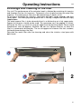
1
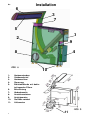
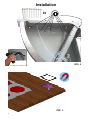
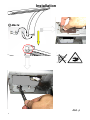
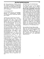
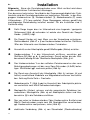
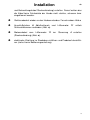
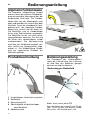
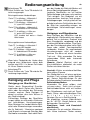
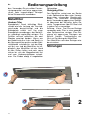
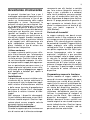
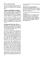
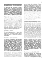
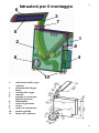
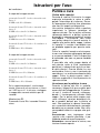
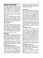
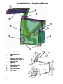
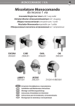
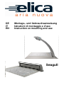
DE
IT
EN
Montage– und Gebrauchsanweisung
Istruzioni di montaggio e d’uso
Instruction on mounting and use
Seagull
de
Installation
6
3
7
5
1
2
9
8
Abb. a
1:
2:
3:
4:
5:
6:
7:
8:
9:
10:
11:
4
10
Haubenunterbau
Gehäusedeckel
Haubenschirm
Steuerung
Edelstahlblende mit dahinterliegenden Filtern
Beleuchtung
Abdeckrosette
Anschlussstutzen
Antriebsmotor
Stellfüße variabel
Lüftermotor
Abb. b
2
11
Installation
Abb. c
3
Installation Vorbereitung
115
155
Abb. d
Abb. e
9xM5x12 Torx
4x M8
Abb. f
4
Installation
Abb. h
0
Abb. g
Abb. i
Abb. j
5
Installation
9x
Abb. k
Abb. L
6
Installation
2xM3x9
Front
Backside
Abb. m
Abb. n
Abb. o
7
Installation
M6x16
Abb. p
8
Installation
Abb. r
(
Abb. s
9
de
Installation
10
Abb. u
Sicherheitshinweise
Sehr geehrte Kundin,
sehr geehrter Kunde,
vielen Dank für Ihre Entscheidung zum
Kauf einer elica Dunstabzugshaube!
Bitte lesen Sie nachfolgende Informationen und Erläuterungen zum sachgemäßen Gebrauch Ihrer neuen Haube aus
dem Hause elica vor der ersten Inbetriebnahme sorgfältig durch. Bitte beachten Sie gleichfalls unsere Bedienungs.- und Montageanleitung sowie die
darin enthaltenen Reinigungsempfehlungen, so dass Sie lange Freude an
Ihrem Gerät haben.
Sicherheitshinweise Bedienung
Die Bedienungs.- und Montageanleitung
enthält wichtige Hinweise, welche beachtet werden müssen, damit die Dunstabzugshaube ohne Gefahr und störungsfrei betrieben werden kann. Bitte
bewahren Sie diese für ein späteres
Nachschlagen auf. Die Ihnen vorliegende Gebrauchsanleitung gilt für mehrere
Geräteausführungen. Es ist möglich,
dass einzelne Ausstattungsmerkmale
beschrieben sind, welche nicht auf Ihr
Modell zutreffen. Die Dunstabzugshaube darf nicht von Personen (einschl.
Kinder) mit eingeschränkten physischen
oder psychischen Fähigkeiten oder
mangels Erfahrung und/oder mangels
Wissen benutzt werden. Kinder müssen
beaufsichtigt werden, um sicherzustellen, dass diese nicht mit dem Gerät
spielen.
Bestimmungsmäßige Verwendung
Die Dunstabzugshaube darf ausschließlich zum Beseitigen des Küchendunstes
oberhalb von Kochgeräten für den privaten Hausgebrauch verwendet werden.
Jede andere Verwendung gilt als sachwidrig. Durch sachwidrige Verwendung
der Haube können Gefahren für Personen und Gegenstände entstehen.
de
Installation
Das Gerät darf nur von einem autorisierten Fachmann unter Beachtung aller
einschlägigen Vorschriften der Stromversorgungsunternehmen sowie der
Bauverordnungsvorschriften der Länder
angeschlossen werden. Beachten Sie
bei der Montage die entsprechende
Anleitung! Beschädigte Geräte dürfen
nicht in Betrieb genommen werden.
Defekte Teile müssen durch Originalteile ersetzt werden. Reparaturen dürfen
nur durch autorisiertes Fachpersonal
durchgeführt werden.
Vergiftungsgefahr!
Wenn die Dunstabzugshaube im Abluftbetrieb gleichzeitig mit anderen raumluftabhängigen Feuerstätten (z. B. holz-,
gas-, öl- oder kohlebefeuerte Geräte) in
einem Raum betrieben wird, können
tödliche Verbrennungsgase durch einen
entstehenden Unterdruck im Raum zurückgeführt werden. Bitte sorgen Sie
daher immer für ausreichend Zuluft! Der
Unterdruck im Raum darf nicht größer
als 4 Pa (0,04 mbar) sein.
Brandgefahr!
Die Dunstabzugshaube darf nie ohne
Fettfilter und muss immer unter Aufsicht
betrieben werden. Überfettete Filter
bedeuten Brandgefahr! Frittieren Sie mit
der Abzugshaube nur unter ständiger
Aufsicht! Achten Sie auf eine regelmäßige Filterreinigung. Flambieren ist mit der
Abzugshaube nicht gestattet!
Vorbereitung Inbetriebnahme
Das Haubenmodell entspricht den einschlägigen Sicherheitsbestimmungen
für Kücheneinrichtungen in Privathaushalten. Die Anforderungen, welche der
Aufstellungsort erfüllen muss, sind in
der zum Gerät gehörenden Benutzerdokumentation beschrieben. Falls Sie über
die Zulässigkeit der Aufstellung in der
vorgesehenen Umgebung Zweifel haben, wenden Sie sich bitte an unseren
Service. Beschädigte Geräte dürfen
nicht in Betrieb genommen werden.
11
de
Sicherheitshinweise
Defekte Teile müssen durch OriginalErsatzteile oder durch von elica benannte Teile ersetzt werden. Reparaturen
dürfen nur durch autorisiertes Fachpersonal durchgeführt werden.
Aktivkohlefilter
Bitte bei in elica Dunstabzugshauben
eingesetzten Aktivkohlefiltern separate
Bedienungsanleitung beachten!
Transport, Auspacken, Aufstellen
Wenn das Gerät aus kalter Umgebung
in den Betriebsraum gebracht wird, kann
Betauung auftreten. Bitte warten Sie bis
das Gerät temperaturangeglichen und
absolut trocken ist, bevor Sie es in Betrieb nehmen. Die Akklimatisationszeit
ist abhängig von Temperaturdifferenz
und Gerät sowie dessen Aufbau. Sie
sollte aber mindestens 12 Stunden
betragen.
Anschluss Stromnetz
Überprüfen Sie, ob die angegebene
Nennspannung des Gerätes mit der
örtlichen Netzspannung übereinstimmt.
Eine falsche Einstellung führt zur Beschädigung bzw. Zerstörung der Geräts.
Überprüfen Sie vor dem Betrieb, ob alle
Kabel und Leitungen einwandfrei und
unbeschädigt sind. Achten Sie insbesondere darauf, dass die Kabel keine
Knickstellen aufweisen, um Ecken herum nicht zu kurz verlegt worden sind
und keine Gegenstände auf den Kabeln
stehen. Achten Sie weiterhin darauf,
dass alle Steckverbindungen fest sitzen.
Eine fehlerhafte Schirmung oder Verkabelung gefährdet Ihre Gesundheit
(elektrischer Schlag) und kann andere
Geräte zerstören. Geräte mit Netzstecker werden mit einer sicherheitsgeprüften Netzleitung des Einsatzlandes ausgerüstet und dürfen nur an eine vorschriftsmäßig geerdete SchutzkontaktSteckdose angeschlossen werden, andernfalls droht elektrischer Schlag. Stellen Sie sicher, dass die Steckdose am
Gerät oder die Schutzkontakt-Steckdose
der Hausinstallation frei zugänglich ist,
12
damit im Notfall oder bei Service– bzw.
Wartungsarbeiten das Netzkabel aus
der Steckdose gezogen werden kann.
Gefahr durch elektrischen Schlag!
Reinigen Sie die Haube nicht mit einem
Dampfreiniger oder mit Wasserdruck.
Beim Reinigen der Haube muss diese
vorher vom Stromnetz getrennt werden.
Sicherheitshinweise Fahrbetrieb
Bitte achten Sie darauf, dass während
des Fahrbetriebes keine Gegenstände
in der unmittelbare Nähe (ca. 5 cm) der
Abdeckrosette / Haube liegen. In den
Haubenschacht fallende Gegenstände
können zur Beschädigung der Haube
führen!
Gefahr
Auf keinen Fall dürfen sich während des
Fahrbetriebs irgendwelche Körperteile in
der Nähe der Absaughaube befinden.
Bitte stellen Sie auch sicher, dass auch
andere Personen (insbesondere Kinder)
sich nicht im Gefahrenbereich befinden.
Gefahr von ernsthaften Verletzungen
durch einquetschen! Diese Haube ist
nicht für Personen (einschl. Kinder) mit
eingeschränkten physischen, sensorischen oder geistigen Fähigkeiten oder
mangels Erfahrung und/oder mangels
Wissen benutzt zu werden. Kinder müssen beaufsichtig werden, um sicherzustellen, dass sie nicht mit dem Gerät
spielen.
Sicherheitshinweise Installation
Montage, Anschluss, Inbetriebnahme
und Reparatur dürfen nur von einer
Fachkraft durchgeführt werden. Diese
Fachkraft kann die geeignete Befestigung und Abluftführung der Dunstabzugshaube bestimmen. Die Befestigung
muss für das Gewicht der Dunstabzugshaube und die Belastung des Untergrunds geeignet sein. Die Auszugswerte
der mitgelieferten Dübel beachten. Diese haben in Abhängigkeit vom Untergrund folgende Werte: Dübel Ø10 mm:
Beton B25 9,4 kN Mauerziegel Z20 5,2
Sicherheitshinweise
KN Kalksandvollstein KSV20 4,8 KN.
Bei anderen unsicheren Untergründen
ist für die sichere Montage der Dunstabzugshaube ein Fachmann für Bauangelegenheiten, z.B. ein Statiker oder Architekt, zu befragen.
Verletzungsgefahr!
Scharfe Kanten können sich fertigungsbedingt im Haubenkörper befinden.
Schutzhandschuhe sind bei der Montage zu tragen.
Gefahr durch elektrischen Schlag
Die Netzspannung muss mit den
Angaben auf dem Typ enschild
übereinstimmen. Dieses befindet sich im
Bereich der Filter im Haubeninneren.
Die Dunstabzugshaube nur an eine
vorschriftsmäßig installierte
Schutzkontaktsteckdose anschließen.
Die Steckdose muss nach der Montage
leicht erreichbar sein, um die
Dunstabzugshaube bei Bedarf von der
Netzspannung trennen zu können. Bei
Festanschluss (z.B. wenn eine
entsprechende Steckdo se nicht
vorhanden ist) darf die
Dunstabzugshaube nur von einer
Elektrofachkraft an die Netzspannung
angeschlossen werden. Für den
Festanschluss muss die
Dunstabzugshaube an einen
Einzelstromkreis mit Trennvorrichtung
angeschlossen werden. Als
Trennvorrichtung gelten Schalter mit
einer Kontaktöffnung von mindestens 3
mm und allpoligen Schaltern, z.B. LSSchalter und Schütze. Vor den Arbeiten
am elektrischen Anschluss der
Dunstabzugshaube den Netzstromkreis/
die Netzstromkreise abschalten. Vor
dem Bohren von Befestigungslöchern
prüfen, dass keine elektrischen
Leitungen durch das Bohren beschädigt
werden können. Der Elektroanschluss
muss so vorbereitet werden, dass die
Dunstabzugshaube damit einfach angeschlossen werden kann. Örtliche Bestimmungen müssen eingehalten werden.
de
Abluftführung (für Abluftbetrieb)
Die Abluft darf nicht in einen Schornstein geführt werden, der für Abgase
von Geräten mit Brennstoffen (z.B. Gas)
benutzt wird. Behördliche Vorschriften
für die Ableitung der Abluft sind zu beachten. Der Abluftweg muss so vorbereitet werden, dass die Dunstabzugshaube damit einfach verbunden werden
kann. Der Abluftschlauch muss knickfrei
verlegt sein. Wenn die Dunstabzugshaube im Abluftbetrieb gleichzeitig mit
anderen raumluftabhängigen Feuerstätten (z.B. holz-, gas-, öl- oder kohlebefeuerte Geräte) in einem Raum betrieben wird, können tödliche Verbrennungsgase durch einen entstehenden
Unterdruck in den Raum zurückgeführt
werden. Der Bediener muss deshalb
jederzeit für eine ausreichende Zuluft
sorgen. Der Unterdruck im Raum darf
nicht größer als 4 Pa (0,04mbar) sein.
Feuerstätte für feste Brennstoffe
Über einer Feuerstätte für feste Brennstoffe, von der eine Brandgefahr (z.B.
Funkenflug) ausgehen kann, ist die
Montage der Dunstabzugshaube nur
dann zulässig, wenn die Feuerstätte
eine geschlossene, nicht abnehmbare
Abdeckung hat.
13
de
Installation
Allgemein: Bevor die Dunstabzugshaube unser Werk verlässt wird diese
einem ausführlichen Funktionstest unterzogen.
Zum besseren technischen Verständnis der Zusammengehörigkeit der Funktionsteile wird die Dunstabzugshaube aus logistischen Gründen in den Baugruppen Haubenschirm (3), Haubenunterbau (1), Abdeckrossette (7) sowie
Lüftermotoren (11) lose geliefert. Diese Baugruppen müssen gemäß der
nachfolgenden Beschreibung installiert werden. Für die Installation sind 2
Fachleute nötig.
Dafür Sorge tragen dass im Unterschrank eine tragende / geeignete
Seitenwand (Abb. d) vorhanden ist welche das Gewicht der Seagull
Haube (~65KG) trägt.
Die Seagull Haube mit zwei Mann aus der Verpackung entnehmen.
Gehäusedeckel (Abb. C + f) am Haubenunterbau entfernen. Stellfüsse
10 an der Unterseite vom Haubenunterbau 1 eindrehen.
Ausschnitt an der Arbeitsplatte gemäß Maßangabe (Abb.e) erstellen.
Haubenunterbau 1 in den Unterschrank einführen, ausrichten ggf.
Stellfüsse 10 (Abb. g, h, i) nachjustieren. Darauf achten das der Haubenschacht bündig mit der Oberkante Arbeitsplatte (Abb. j) ist.
Den Haubenunterbau 1 an der seitlichen Zwischenwand an den neun
Befestigungsbohrungen mit den neun Spax Schrauben (4,5x30) befestigen. Winklichkeit ggf. nochmals prüfen (Abb. k).
Der Rand vom Ausschnitt der Arbeitsplatte (Abb. L) reinigen (öl und
fettfrei) anschließend Klebefolie am Magnetband entfernen und aufkleben. Achtung Breite Seite = Frontseite.
Abdeckrossette 7, (Abb. L+m) im Ausschnitt der Arbeitsplatte platzieren und mittels zwei M3x9 Schrauben befestigen.
Montagehilfe (Karton) nehmen und die vorgestanzte Schablone herausbrechen, Montagehilfe (Abb. n) auf Arbeitsplatte stellen und Haubenschirm (3) in die Schablone einführen.
Nun von unten im Haubenunterbau 1 den Haubenschirm 3 mittels zwei
M6x16 Senkschrauben sowie zwei M6 Gewindestiften verschrauben,
ggf. Haubenschirm nachjustieren, siehe (Abb. P).
elektrische Verbindung (Abb. r) von Steuerkabel (Steckverbindung)
14
de
Installation
und Beleuchtungskabel Steckverbindung) erstellen. Darauf achten das
die Kabel beim Fahrbetrieb der Haube nicht streifen, scheuern bzw.
eingeklemmt werden.
Gehäusedeckel wieder an den Haubenunterbau 1 anschrauben Abb.s.
Anschlußstutzen 8 Abluftschlauch und
Schlauchklemmen verbinden (Abb. u).
Lüftermotor
Motorenkabel vom Lüftermotor
(Steckverbindung) (Abb. u).
Steuerung 4 erstellen
elektrische Zuleitung im Steckdose einführen und Probelauf durchführen (siehe hierzu Bedienungsanleitung).
11
zur
11
mittels
15
de
Bedienungsanleitung
Allgemeine Funktionsweise
Die innovative Muldenlüftung Seagull
offeriert durch die effektive Randabsaugung eine perfekte Absaugung über der
eingesetzten Kochstelle. Der Haubenkörper fährt von der Arbeitsplatte nach
oben und befindet sich zentral über dem
Kochfeld. Durch die durchdachte Formgebung wirkt der eigentliche Haubenkörper sehr schlank und fällt kaum auf.
Die Metallfilter sind im Haubenkörper
hinter einer Edelstahlplatte angeordnet.
Die Metallfilter lassen sich ohne Werkzeug problemlos wechseln. Das Auf und
Ab fahren des Haubenkörpers erfolgt
motorbetrieben. Die Absaugleistung
wird über das Bedienfeld geregelt welches seitlich am Haubenschirm angeordnet ist. Die Muldenlüftung Seagull
wird aus hygienischen Gründen aus
Edelstahl gefertigt.
Produktbeschreibung
1
Bedienungsanleitung
Die Funktionen des Haubenmodells
sowie die Lüfterleistung vom Lüftermotor wird über das Bedienteil geregelt
welchen wie folgt funktioniert:
Bedienung per Bedienfeld
3
4
T2
2
T3
L1
5
Haubenkörper (Haubenkörper ausgefahren)
Bedienfeld
Beleuchtung (LED)
Edelstahlplatte mit dahinterliegen
dem Metallfilter
5 Abdeckrossette
1
2
3
4
16
T1
Haube hoch—runter fahren T1
Zum hochfahren der Haube Taste T1 drücken. Taste T1 noch mal drücken Haube
fährt runter. LED leuchtet weiss, hell
Bedienungsanleitung
Lüfterleistung T2
Durch Drücken der Taste T2 wird die Lüfterleistung geregelt.
Bei eingefahrenem Haubenkörper:
Taste T2 1x drücken = Lüfterstufe 1
L1 grünes LED leuchtet.
Taste T2 2x drücken = Lüfterstufe 2
L1 cyan LED leuchtet.
Taste T2 3x drücken = Lüfterstufe 3
L1 dunkelblaue LED leuchtet.
Taste T2 4x drücken = Lüfter aus
L1 weise LED leuchtet.
LED leuchtet hell weiss = Haube
fährt heraus
Bei ausgefahrenem Haubenkörper:
Taste T2 1x drücken = Lüfterstufe 2
L1 cyan LED leuchtet
Taste T2 2x drücken = Lüfterstufe 3
L1 dunkelblaue LED leuchtet.
Taste T2 3x drücken = Lüfter aus
L1 weise LED leuchtet.
Wenn beim Fahrbetrieb der Haube diese
eines Widerstands stehen bleib
leuchtet rote LED L1. In diesem Fall Haube
für 10 sec. Stromlos machen.
aufgrund
Beleuchtung T3
Durch Drücken der Taste T3 wird die Beleuchtung eingeschaltet.
Reinigung und Pflege
Reinigung von Oberflächen
Gefahr durch Stromschlag! Dunstabzugshaube durch Ziehen des Netzsteckers oder Ausschalten der Sicherung
stromlos machen. Beim Reinigen ist
darauf zu achten, dass kein Wasser in
das Gerät eindringt.
Frühzeitiges Reinigen der Oberfläche
erspart später ein mühevolles Entfernen
von hartnäckigen Verschmutzungen.
Beim Reinigen nur handelsübliche Spülmittel oder Allzweckreiniger verwenden,
die für Edelstahl / Aluminium geeignet
sind. Niemals scheuernde Reiniger oder
Stahlwolle verwenden. Nach dem Reini-
de
gen der Haube die Edelstahlflächen mit
einem Edelstahlpflegemittel pflegen.
Lackierte Oberflächen nur mit leichter
Spülmittellauge und einem sehr weichen
Tuch reinigen. Das Bedienteil nur mit
einem weichen, feuchten Tuch reinigen.
Fettablagerungen sind physikalisch begründet und keine Fehlfunktion der Haube. Bitte hier regelmäßig reinigen, um
hartnäckigen Verschmutzungen vorzubeugen.
Reinigungs- und Pflegehinweise
Beim Reinigen der Metallfilter sind die
zugänglichen Gehäuseteile von abgelagertem Fett zu befreien. Dadurch wird
einer Brandgefahr vorgebeugt und die
Funktionalität bleibt erhalten. Zum Reinigen der Dunstabzugshaube heiße Spüllauge oder mildes Fensterputzmittel
verwenden. Kratzen Sie angetrocknete
Verschmutzungen nicht ab, sondern
weichen Sie diese mit einem feuchten
Tuch auf. Bitte verwenden Sie keine
scheuernden Mittel oder kratzende
Schwämme.
Hinweis: Alkohol (Spiritus) nicht auf
Kunststoffflächen anwenden, da matte
Stellen entstehen könnten.
Vorsicht: Küche ausreichend belüften,
keine offene Flamme.
Das Bedienfeld nur mit einem weichen,
feuchten Tuch reinigen (milde Spüllauge). Keinen Edelstahlreiniger für den
Schiebeschalter/Drucktaster verwenden.
Edelstahloberflächen:
Verwenden Sie einen milden, nicht
scheuernden Edelstahlreiniger.
Edelstahloberflächen nicht mit kratzenden Schwämmen und nicht mit Sand-,
Soda-, Säure- oder chloridhaltigen Putzm i t t e l n
r e i n i g e n !
Reinigen Sie nur in Schliffrichtung.
Wir empfehlen unseren Edelstahlreiniger Nr. 461731. Bestell-Adresse siehe
beiliegendes Service-Heft.
Aluminium-, Lack- und Kunststoffoberflächen:
Verwenden Sie ein weiches Mikrofasertuch. Keine trockenen Tücher verwen17
de
Bedienungsanleitung
den. Verwenden Sie ein mildes Fensterreinigungsmittel und keine aggressiven,
säure- oder laugenhaltigen Reiniger!
Keine Scheuermittel verwenden.
Metallfilter
Ausbau Filter
Brandgefahr! Durch fetthaltige Rückstände wird die Leistung der Dunstabzugshaube beeinträchtigt und die
Brandgefahr erhöht sich. Um einer
Brandgefahr vorzubeugen, den Metallfilter unbedingt regelmäßig reinigen. Die
Fettfilter müssen spätestens alle zwei
Wochen gereinigt werden. Hierzu von
der Bedienseite aus Links und Rechts in
die Absaugschlitze greifen und die Edelstahlblende anheben bis sich der Magnet löst, nun sind die Metallfilter frei zugänglich, den Metallfilter mit der Hand
an den Griffen halten und nach vorne
ziehen bis sich der Magnetkontakt löst
und vom Haubenunterkörper entnehmen. Der Einbau erfolgt in umgekehrter
Reihenfolge.
Reinigung Filter
Den Metallfilter reinigt man am Besten
in der Spülmaschine oder unter Verwendung eines schonenden Geschirrspülmittels. Für eventuelle Verfärbungen
durch Verwendung aggressiver Spülmittel übernimmt der Hersteller keine Garantie. Temperaturen über 55 Grad sind
in jedem Fall zu vermeiden.
Achtung: Keine Drei-Phasen-Reiniger
verwenden oder Filter in einer gewerblichen Spülmaschine reinigen. Eine Reinigung mit aggressiven Reinigern wie
Benzin, Aceton, Trichlorethylen etc.
führt zur Zerstörung der Metallfilter!
Den Metallfilter nach dem Reinigen wieder einsetzen.
Störungen
1
2
18
Bedienungsanleitung
Wenden Sie sich bitte sofort an unseren
Kundendienst, wenn:
-die Dunstabzugshaube undefinierbare
Geräusche verursacht und Sie nach
Prüfung der Abluftleitung keine Mängel
feststellen können;
-Sie feststellen, z.B. durch Hören seltsamer Geräusche, dass der Motor fehlerhaft oder defekt ist;
-die Schaltung nicht ordnungsgemäß
funktioniert.
- die Haube nicht mehr heraus fährt
bzw. zurück fährt.
Bitte geben Sie unbedingt die Bezeichnung des Typs Ihrer Dunstabzugshaube
und die dazugehörige Serien-Nummer
an. Sie finden diese Angaben auf dem
Typenschild. Dieses befindet sich im
Bereich der Metallfilter im Haubeninnern.
Entsorgung
de
Verpackung
Die Verpackung der Dunstabzugshaube
ist recycelbar. Als Verpackungsmaterialien werden Karton und Polyethylenfolie
(PE) verwendet. Diese Materialien sind
umweltgerecht und nach den jeweiligen
vor Ort geltenden Vorschriften zu entsorgen.
Dunstabzugshaube
Über eine umweltgerechte Beseitigung veralteter Haushaltsgeräte
berät Sie auch gerne Ihre Gemeinde.
Umwelthinweise
Alle Modelle aus dem Hause
elica sind entsprechend der europäischen Richtlinie 2002/96/EG über
Elektro- und Elektronikgeräte (waste
electrical and electronic equipment –
WEEE) gekennzeichnet. Diese Richtlinie gibt die Rahmenbedingungen für
eine EU-weit gültige Rücknahme und
Verwertung von Altgeräten vor. Bitte
informieren Sie sich über aktuelle Entsorgungswege bei Ihrem Fachhändler.
Technische Änderungen vorbehalten.
19
it
elica godetevi la vita
Gentile Cliente,
La ringraziamo per aver scelto una cappa aspirante elica!
La preghiamo di leggere attentamente le seguenti informazioni e spiegazioni per un
utilizzo corretto del Suo nuovo modello di cappa elica prima di metterla in funzione. La
preghiamo di osservare inoltre le nostre istruzioni per l'uso e per il montaggio oltre ai
consigli per la pulizia in esse contenuti: Le permetteranno di godersi il Suo nuovo
acquisto più a lungo.
20
it
Avvertenze di sicurezza
Le presenti istruzioni per l'uso e per il
montaggio contengono importanti avveravvertenze da osservare al fine di garantire un funzionamento della cappa
impeccabile e sicuro. Conservare le
presenti istruzioni per consultazioni future. Le presenti istruzioni per l'uso sono
applicabili a dispositivi di diverse versioni. È possibile che alcune delle dotazioni
accessorie qui descritte non siano disponibili nel modello in Suo possesso.
La cappa aspirante non può essere azionata da soggetti (bambini compresi)
con attitudini fisiche o psichiche limitate
o da soggetti privi dell'esperienza e/o
della competenza necessarie. Sorvegliare i bambini al fine di evitare che
giochino con il dispositivo.
Utilizzo conforme
La cappa aspirante potrà essere utilizzata esclusivamente per l'eliminazione
dei vapori da cucina sopra piani di cottura d'uso privato. Qualsiasi utilizzo diverso sarà considerato improprio. Un utilizzo improprio della cappa può rappresentare un pericolo per persone o cose. La
cappa aspirante non potrà essere utilizzata come piano d'appoggio per oggetti
quali bottiglie o barattoli per spezie o
altri oggetti sciolti.
Installazione
Il dispositivo può essere installato esclusivamente da un tecnico autorizzato in
osservanza di tutte le disposizioni applicabili relative all'alimentazione elettrica
e delle norme tecniche di progettazione
del paese di utilizzo. Per il montaggio,
consultare le relative istruzioni di montaggio!
Non azionare i dispositivi danneggiati.
Le parti difettose dovranno essere sostituite con ricambi originali. Qualsiasi riparazione dovrà essere eseguita solo da
personale tecnico autorizzato.
Pericolo di intossicazione!
Quando la cappa aspirante funziona con
aria di scarico ed è utilizzata contempo-
raneamente con altri focolari a contatto
con l'aria esterna (dispositivi azionati a
legna, a gas, a petrolio o a carbone)
nello stesso ambiente, possono sprigionarsi gas di combustione letali per via
della formazione di depressione nell'ambiente. Si prega pertanto di garantire in
ogni momento un ricircolo d'aria sufficiente! La depressione nel locale di utilizzo non potrà superare 4 Pa
(0,04,04mbar).
Pericolo di incendio!
La cappa aspirante non dovrà essere
azionata senza il filtro antigrasso e dovrà sempre essere utilizzata sotto sorveglianza. Filtri saturati di grasso significano pericolo di incendio! Friggere sotto la
cappa aspirante solo sotto costante
sorveglianza! Fare in modo di garantire
una pulizia regolare dei filtri. Non è permesso fiammeggiare sotto la cappa
aspirante! I dispositivi a gas possono
essere impiegati sotto la cappa aspirante solo con la pentola appoggiata sul
fuoco! Qualora si utilizzassero simultaneamente più di 3 piani cottura a gas,
azionare la cappa aspirante alla velocità
2 o superiore. In questo modo si eviterà
un accumulo di calore all'interno del
dispositivo.
Preparazione messa in funzione
Questo modello di cappa soddisfa le
norme di sicurezza applicabili alle apparecchiature per cucine d'uso privato. I
requisiti che la zona di installazione deve soddisfare sono specificati nel manuale utente del dispositivo specifico. In
caso di dubbi rispetto all'idoneità all'installazione dell'ambiente previsto per
l'utilizzo, La preghiamo di rivolgersi al
nostro servizio clienti. Non azionare i
dispositivi danneggiati. I componenti
difettosi dovranno essere sostituiti con
ricambi originali o con ricambi espressamente indicati da elica. Qualsiasi riparazione dovrà essere eseguita solo da
personale tecnico autorizzato.
21
it
Filtro a carbone attivo
Per i filtri a carbone attivo (versione C)
utilizzati nelle cappe aspiranti elica, osservare le istruzioni per l'uso corrispondenti!
Trasporto, disimballaggio e montaggio
Quando il dispositivo viene trasportato
da un ambiente freddo nel luogo di utilizzo, può prodursi della condensa. Attendere finché il dispositivo si sia adattato alla temperatura e sia completamente
asciutto prima di procedere alla sua
messa in funzione. Il tempo di acclimatazione varia in funzione dell’escursione
termica e dell’apparecchio specifico e
della sua composizione; tuttavia, in ogni
caso non dovrebbe essere inferiore alle
12 ore.
Collegamento alla rete elettrica
Accertarsi che la tensione nominale del
dispositivo corrisponda alla tensione di
rete del luogo di utilizzo. Una regolazione scorretta causerebbe danni o la distruzione del dispositivo.
Prima del funzionamento, verificare che
tutti i cavi e circuiti siano impeccabili e
privi di danneggiamenti. Sincerarsi soprattutto che i cavi non presentino incrinature, che non siano stati tirati eccessivamente in prossimità degli angoli e che
non siano schiacciati da oggetti. Assicurarsi inoltre che tutti i collegamenti siano
ben saldi. Una schermatura o un cablaggio erronei possono compromettere
la Sua salute (scosse elettriche) e mettere fuori uso altre apparecchiature. I
dispositivi dotati di una spina sono equipaggiati con un cavo di rete testato in
base alle norme di sicurezza del paese
di utilizzo e possono essere collegati
solo a prese con contatto di protezione
con regolare messa a terra; in caso contrario, sussiste il rischio di scosse elettriche. Assicurarsi che la presa sul dispositivo o la presa con contatto di protezione dell'impianto interno siano accessibili
liberamente, in modo tale da poter scollegare il cavo dalla presa di corrente in
22
caso di emergenza o per manutenzioni
o riparazioni.
Pericolo di scossa elettrica!
Non pulire la cappa con pulitori a vapore
o a pressione idraulica. Prima di procedere alla pulizia, scollegare la cappa
dalla presa di corrente.
Avvertenze di sicurezza durante il funzionamento
Si prega di accertarsi che durante il funzionamento non vi siano oggetti nelle
immediate vicinanze (ca. 5 cm) della
rosetta di protezione / della cappa aspirante. La caduta di oggetti nel pozzetto
della cappa aspirante può causarne il
danneggiamento!
it
Avvertenze di sicurezza
Le operazioni di montaggio, collegamento, messa in funzione e riparazione
dovranno essere effettuate da personale
specializzato, che potrà determinare la
modalità di fissaggio e i condotti per
l'aria di scarico più indicati per la cappa
aspirante. La tecnica di fissaggio dovrà
essere idonea a sopportare il peso della
cappa aspirante e il carico del supporto.
Rispettare i valori di estrazione dei tasselli forniti in dotazione che, a seconda
del supporto utilizzato, saranno i seguenti: tassello Ø10 mm: cemento B25
9,4 kN mattone da costruzione Z20 5,2
KN mattone in pietra calcarea KSV20
4,8 KN. In presenza di supporti diversi
non altrettanto sicuri è opportuno consultare un esperto in materia di costruzioni (un ingegnere calcolatore o un
architetto) al fine di garantire un montaggio sicuro della cappa aspirante.
Pericolo di lesioni!
Per motivi di produzione, il corpo della
cappa può presentare spigoli aguzzi.
Indossare guanti di protezione durante il
montaggio.
Pericolo di scossa elettrica
La tensione di rete deve corrispondere
ai valori indicati sulla targhetta segnaletica posta in prossimità del filtro, all'interno della cappa. Collegare la cappa
aspirante solo a prese con contatto a
terra regolarmente installate. A montaggio ultimato, la presa dovrà essere facilmente accessibile per permettere di
scollegare la cappa dalla tensione di
rete in caso di necessità. In caso di collegamento fisso (ad es. quando non si
ha a disposizione una presa idonea), la
cappa aspirante potrà essere collegata
alla tensione di rete solamente da un
elettricista specializzato. In presenza di
un collegamento fisso, la cappa aspirante dovrà essere collegata a un circuito a
massa dotato di disgiuntore. Come
disgiuntori è possibile utilizzare interruttori con un'apertura di contatto superiore ai 3 mm e interruttori onnipolari
(interruttori automatici e relè). Prima di
effettuare qualsiasi intervento sull'impianto elettrico della cappa aspirante,
disinserire il/i circuito/i di rete. Prima di
applicare i fori di fissaggio, assicurarsi
di non danneggiare alcun circuito elettrico durante la perforazione della parete. Predisporre il collegamento elettrico in modo tale da potervi collegare
la cappa aspirante con facilità. Osservare le disposizioni locali.
Condotto dell'aria di scarico (per il
funzionamento con aria di scarico)
L'aria di scarico non può essere condotta nei camini comunemente impiegati per i gas di scarico dei macchinari
che utilizzano combustibile (ad esempio gas). Osservare le disposizioni
ufficiali inerenti al deflusso dell'aria di
scarico. Predisporre il condotto dell'aria di scarico in modo tale da potervi
collegare la cappa aspirante con facilità. Il condotto di uscita per l'aria di
scarico dovrà essere posato evitando
incrinature. Quando la cappa aspirante
funziona con aria di scarico ed è utilizzata contemporaneamente con altri
focolari a contatto con l'aria esterna
(dispositivi azionati a legna, a gas, a
petrolio o a carbone) nello stesso ambiente, possono sprigionarsi gas di
combustione letali per via della formazione di depressione nell'ambiente.
L'utilizzatore dovrà pertanto garantire
in ogni momento un ricircolo dell'aria
sufficiente. La depressione nel locale
di utilizzo non potrà superare 4 Pa
(0,04mbar).
Focolari per combustibili solidi
Nel caso di focolari per combustibili
solidi che suppongono un rischio di
incendio (ad esempio scintille volanti),
si autorizza il montaggio di una cappa
23
it
aspirante solo quando il focolare è provvisto di una copertura chiusa e non asportabile.
Disposizioni di sicurezza durante il movimento della cappa
Fare attenzione che durante il movimento della cappa non si trovino oggetti
nelle immediate vicinanze (ca. 5 cm)
della rosette di copertura. Oggetti che
cadono nella fessura della cappa possono causare danneggiamenti alla cappa!
Pericolo
In nessun caso durante il movimento
della cappa devono essere presenti
parti del corpo nelle immediate vicinanze della cappa. Inoltre è necessario
provvedere affinché nessun altra persona (in particolare bambini) si trovi nella
zona di pericolo. Pericolo di ferite gravi
a causa di schiacciamenti! La cappa
deve anche essere dotata di un comando di sicurezza elettronico
24
6
it
Istruzioni per il montaggio
3
7
5
1
2
9
8
4
10
1:
2:
3:
4:
5:
6:
7:
8:
9:
10:
11:
sottostruttura della cappa
aspirante
protezione dell'alloggia
mento
schermo della cappa
comandi
pannello in acciaio inox
con filtri posteriori
illuminazione
rosetta di protezione
attacco
motore di azionamento
piedini regolabili
motore del ventilatore
25
it
Istruzioni per il montaggio
Aspetti generali: prima di lasciare la nostra fabbrica, le cappe aspiranti vengono sottoposte a un test di funzionamento completo.
Per una miglior comprensione dal punto di vista tecnico dei collegamenti delle singole parti funzionanti, la cappa aspirante viene fornita per motivi logistici
in diversi moduli sfusi: schermo (3), sottostruttura (1), rosetta di protezione (7)
e motori ventilatore (11). Tali moduli devono essere installati in base alle istruzioni di seguito riportate. L'installazione richiede l'intervento di 2 professionisti.
26
Assicurarsi che nella base sia integrato un pannello
laterale portante/idoneo (fig. d) in grado di sopportare il
peso della cappa Seagull (~ 65 kg).
Con l'aiuto di una seconda persona, estrarre la cappa
Seagull dall'imballaggio. Rimuovere la protezione
dell'alloggiamento (fig. C + f) dalla sottostruttura della
cappa. Avvitare i piedini regolabili 10 sul lato inferiore
della base della sottostruttura della cappa 1.
Applicare un'apertura sul piano di lavoro in base alle
misure (fig.e) .
Inserire la sottostruttura della cappa 1 nella base e
allinearla; se necessario, regolare i piedini 10 (fig. g, h,
i) per adattarli. Accertarsi che il pozzetto della cappa
sia a filo con il bordo superiore del piano di lavoro (fig.
j) .
Fissare la sottostruttura 1 alla parete intermedia laterale ai nove fori di fissaggio servendosi delle nove viti
Spax (4,5x30). Eventualmente ricontrollare l'angolatura (fig. k).
Pulire il bordo del ritaglio sul piano di lavoro (fig. L)
(deve essere privo di olio e grasso), quindi rimuovere
la pellicola adesiva dal nastro magnetico e incollare.
Fare attenzione: il lato largo è quello frontale.
Posizionare la rosetta di protezione 7, (fig. L+m) nel
ritaglio del piano di lavoro e fissarla mediante due viti
M3x9.
Istruzioni per il montaggio
Servendosi del cartone di supporto per il montaggio,
estrarre la dima preformata, collocare il supporto per
il montaggio (fig. n) sul piano di lavoro e inserire lo
schermo della cappa (3) nella dima.
A questo punto, dal lato inferiore della sottostruttura
della cappa 1 avvitare lo schermo 3 con due viti
M6x16 a testa svasata e due viti M6 senza testa, se
necessario regolare nuovamente lo schermo, vedere
(fig. P).
Effettuare il collegamento elettrico (fig. r) del cavo di
comando (connettore) e del cavo dell'illuminazione
(connettore), accertandosi che i cavi non si strofinino
e che non rimangano schiacciati o intrappolati durante il funzionamento della cappa.
Riavvitare la protezione dell'alloggiamento alla sottostruttura della cappa 1 Immagine in alto
Collegare l'attacco 8, il condotto di uscita per l'aria di
scarico e il motore del ventilatore 11 mediante fascette serratubo (immagine in basso).
Predisporre il cavo del motore del ventilatore 11 per il
comando 4 (connettore) (immagine in basso).
Inserire il cavo di alimentazione nella presa ed eseguire una prova di funzionamento (a tale scopo consultare le istruzioni per l'uso).
it
27
it
Istruzioni per l'uso
Funzionamento generale
L'innovativa ventilazione concava Seagull garantisce un'aspirazione perfetta
sopra la zona di cottura utilizzata, grazie
alla sua efficace aspirazione periferica.
Il corpo della cappa si muove dal piano
di lavoro verso l'alto ed è centrato rispetto al piano cottura. Grazie al suo
design sofisticato, il corpo della cappa in
sé appare molto sottile e assolutamente
discreto. I filtri in metallo sono posizionati nel corpo della cappa dietro una
piastra in acciaio inossidabile. I filtri in
metallo si possono sostituire facilmente
senza l'impiego di utensili. Il sollevamento e l'abbassamento del corpo della
cappa avviene grazie a un motore. La
forza di aspirazione è regolata attraverso il pannello di comando, che è disposto lateralmente sul braccio della cappa.
Per motivi igienici, la cappa ad aspirazione concava Seagull viene realizzata
in acciaio inossidabile.
Istruzioni
per
l'uso
Le funzioni del modello di cappa aspirante così come la potenza del motore
del ventilatore sono comandate attraverso il pannello di comando; segue una
descrizione del suo funzionamento:
Descrizione del prodotto
Comandi sul pannello di comando
Sollevamento/abbassamento della cappa T1
1
3
4
Per sollevare la cappa, premere il tasto
T1 .
Premere nuovamente il tasto T1 per abbassare la cappa.
Potenza del ventilatore T2
Premendo il tasto T2 si regola la potenza
2
T2
T3
5
1
Corpo della cappa (corpo della
L1
cappa estratto)
2
3
4
5
28
Pannello di comando
Illuminazione (LED)
Piastra in acciaio inox che copre
il filtro in metallo disposto dietro
Rosetta di protezione
T1
Istruzioni per l'uso
del ventilatore.
A corpo della cappa retratto:
premendo il tasto T2 1 volta = intensità ventilatore 1
Il LED verde L1 si illumina.
Premendo il tasto T2 2 volte = intensità ventilatore 2
Il LED color ciano L1 si illumina.
Premendo il tasto T2 3 volte = intensità ventilatore 3
Il LED blu scuro L1 si illumina.
Premendo il tasto T2 4 volte = il ventilatore si
spegne
Il LED bianco L1 si illumina.
A corpo della cappa retratto:
premendo il tasto T2 1 volta = intensità ventilatore 2
Il LED color ciano L1 si illumina
Premendo il tasto T2 2 volte = intensità ventilatore 3
Il LED blu scuro L1 si illumina.
Premendo il tasto T2 3 volte = il ventilatore si
spegne
Il LED bianco L1 si illumina.
Se la cappa interrompe il suo funzionamento a causa di una resistenza, si illumina il LED rosso L1. In tal caso, scollegare
la cappa dalla corrente elettrica per 10
secondi.
Illuminazione T3
Premendo il tasto T3 si accende l'illuminazione.
it
Pulizia e cura
Pulizia delle superfici
Pericolo di scossa! Disinserire la cappa
aspirante estraendo la spina o scollegando l'interruttore di sicurezza. Durante l'operazione di pulizia fare attenzione
che non filtri acqua nel dispositivo.
Una pulizia tempestiva della superficie
risparmierà la faticosa rimozione di
sporco ostinato. Per la pulizia utilizzare
solamente detersivi o pulitori universali
disponibili in commercio adatti all'acciaio
inossidabile / all'alluminio. Non usare
mai pulitori abrasivi o lana di acciaio. In
seguito alla pulizia della cappa, trattare
le superfici in acciaio inossidabile con
un prodotto apposito per questo materiale.
Pulire le superfici laccate esclusivamente con una soluzione detergente delicata
e un panno morbido. Pulire il dispositivo
di comando solo con un panno morbido
umido.
È possibile che nelle cappe dotate di
una piastra sotto al filtro (aspirazione
periferica) si depositi del grasso sui bordi della piastra. Questo effetto ha una
motivazione fisica e non è pertanto da
considerarsi un malfunzionamento della
cappa. Pulire la piastra posta sotto il
filtro con regolarità al fine di prevenire lo
sporco ostinato.
Avvertenze per la pulizia e la cura
Durante la pulizia dei filtri in metallo,
rimuovere i depositi di grasso dalle parti
accessibili dell'alloggiamento. Si preverrà così il rischio di incendi, salvaguardando il funzionamento ottimale della
cappa. Per la pulizia della cappa aspirante utilizzare soluzioni detergenti calde o prodotti delicati per la pulizia di
vetri. Non grattare lo sporco incrostato,
ma rimuoverlo delicatamente ammorbidendolo con un panno umido. Non utilizzare prodotti abrasivi o spugne che graffiano.
Avvertenza: non impiegare alcol
(spirito) sulle superfici plastiche, si potrebbero produrre macchie opache.
Attenzione: aerare bene la cucina, non
lasciare fiamme aperte.
29
it
Pulire il pannello di comando solo con
un panno morbido umido (soluzione
detergente delicata). Non utilizzare pulitori per acciaio inossidabile per gli interruttori a scorrimento / i pulsanti.
Superfici in acciaio inossidabile:
utilizzare un pulitore per acciaio inossidabile delicato e non abrasivo. Non pulire le superfici in acciaio inossidabile con
spugne che graffiano o con detersivi
contenenti sabbia, soda, acidi o cloruri!
Pulire solo nel senso della molatura.
Raccomandiamo il nostro pulitore per
acciaio inossidabile num. 461731. Indirizzo per le ordinazioni vedi libretto di
assistenza allegato.
Superfici laccate, in alluminio e in
plastica:
utilizzare un panno in microfibra morbido. Non usare panni asciutti. Utilizzare
un pulitore per vetri delicato; mai utilizzare pulitori aggressivi o contenenti acidi o alcali!
Non utilizzare prodotti
abrasivi.
Smontaggio e pulizia del
filtro metallico*
Pericolo d’incendio! A causa dei residui
di grasso la potenza della cappa diminuisce e il pericolo d’incendio aumenta.
Per limitare il pericolo d’incendio, pulire
il filtro metallico regolarmente. I filtri antigrasso devono essere puliti al massimo
ogni 2 settimane.
Nelle cappe con la piastra posta sotto al
filtro (aspirazione ai margini), la piastra
deve essere girata: premere verso l’alto
con entrambe le mani la piastra e abbassarla lentamente. Prendere il filtro
metallico per le maniglie con entrambe
le mani e tirarlo verso il basso finché
non si stacca dal magnete. Ora il filtro
può essere tirato verso il basso. Per il
montaggio procedere al contrario.
Per la pulizia ottimale del filtro metallico
si consiglia l’utilizzo della lavastoviglie e
di un detergente delicato. Non rientra
nella garanzia del produttore un eventuale scolorimento per l’impiego di un detergente per lavastoviglie aggressivo. In
30
ogni caso evitare temperature al di sopra dei 55°.
Attenzione: non impiegare detergenti del
tipo „3 in 1“. Non usare lavastoviglie
industriali. La pulizia con detergenti aggressivi, quali benzina, acetone, tricloroetileno, ecc., potrebbe rovinare il filtro!
Reinserire il filtro metallico a pulizia avvenuta. Nei modelli ad aspirazione ai
margini, la piastra deve essere riposta
nella sua posizione originale a pulizia
avvenuta. Quindi, premere la piastra
verso l’alto con entrambe le mani, finché
non scatta.
Illuminazione
Modello standard con illuminazione
LED! La sostituzione delle lampadine
LED può essere eseguita solo dal servizio clienti!
it
Guasti
Smaltimento
Rivolgersi subito al nostro servizio clienti
quando:
Imballaggio
• - la cappa aspirante emette rumori
indefinibili e non si siano constatate
irregolarità nel corso del controllo del
condotto dell'aria di scarico;
• - è possibile constatare (ad es. per
via dell'insorgere di strani rumori),
che il motore è difettoso o guasto;
• - il circuito non funziona correttamente.
È imprescindibile indicare il modello
completo della cappa aspirante e il numero di serie corrispondente. Troverà
queste informazioni sulla targhetta segnaletica, posta in prossimità del filtro in
metallo, all'interno della cappa.
L'imballaggio della cappa aspirante è
riciclabile. Come materiale di imballaggio vengono impiegati cartone e pellicola di polietilene (PE). Questi materiali
vanno smaltiti in modo rispettoso
dell'ambiente e in conformità alle norme
relative vigenti.
Cappa aspirante
La Sua amministrazione comunale Le
fornirà assistenza circa il corretto smaltimento delle apparecchiature domestiche usate.
Nota ambientale
Tutti i modelli di produzione elica sono
contrassegnati in base alla Direttiva
europea 2002/96/CE sulle apparecchiature elettriche ed elettroniche (waste
electrical and electronic equipment –
WEEE), la quale sancisce i criteri base
per il ritiro e il ricupero di apparecchiature usate, validi su tutto il territorio UE.
La preghiamo di rivolgersi al Suo rivenditore specializzato per informazioni
sulle diverse modalità di smaltimento
attuali.
Modifiche tecniche riservate.
31
en
elica to help you enjoy life
Dear customer,
Thank you for choosing a elica extractor hood.
Please carefully read the following information and explanations on the proper use of
your new elica hood before using the appliance for the first time. Please also read our
operating and installation instructions as well as the cleaning recommendations to
ensure that you enjoy many years of service from your appliance.
32
en
Safety information
These operating and installation instructions contain important information that
must be observed to ensure safe and
reliable operation of the extractor hood.
Please store them in a safe place for
future reference. These operating instructions refer to several versions of the
appliance. They may contain descriptions of certain features not found on
your model.
The extractor hood must not be used by
persons (incl. children) with impaired
physical or mental capabilities or persons who lack experience and/or knowledge of how to use it. Children must be
supervised to ensure that they do not
play with the appliance.
Intended use
The extractor hood may only be used to
extract kitchen vapours above the cooking appliances in private households.
Any other use will be deemed to be improper. Improper use of the hood may
pose a danger to persons and objects.
The extractor hood must not be used as
a shelf to store objects such as bottles,
spice jars or other loose objects.
Installation
The appliance may only be installed and
connected by an authorised technician
observing all relevant regulations of the
electric utility companies and the applicable building regulations. During installation, observe the relevant instructions!
Damaged appliances may not be put
into operation. Defective parts must be
replaced with genuine parts. Repairs
should only be carried out by authorised
technical staff.
Danger of intoxication!
If the extractor hood is operated in extraction mode at the same time as other
room-air-dependent fire appliances (e.g.
wood, gas, oil or coal-fired appliances)
in the same room, lethal combustion
gases may be directed back into the
room due to the resulting negative pres-
sure. For this reason, you must ensure
a sufficient air supply at all times! The
negative pressure in the room must not
exceed 4 Pa (0.04mbar).
Fire hazard!
The extractor hood must never be operated without the grease filter and
must always be used under supervision. Filters that are saturated with
grease can pose a fire hazard! Keep
the extractor hood under constant supervision when deep-frying! Remember
to clean out the filters regularly. Flambéing under the extractor hood is not
allowed! Gas appliances may only be
used under the extractor hood with
saucepans placed over them! If you are
using more than three gas rings at the
same time, operate the extractor hood
at power level "2" or higher. This prevents the build-up of heat in the appliance.
Preparing for use
The extractor hood model complies
with the relevant safety regulations for
kitchen appliances in private households. The requirements regarding the
installation location are described in the
user documentation supplied with the
appliance. If you have any doubts as to
whether your intended installation location meets the requirements, please
contact our service department. Damaged appliances may not be put into
operation. Defective parts must be replaced with genuine spare parts or
parts specified by elica. Repairs should
only be carried out by authorised technical staff.
Activated carbon filter
For activated carbon filters fitted in
GUTMANN extractor hoods (C Version), please read the separate operating instructions provided!
Transport, unpacking, installation
Condensation may occur if the appliance is brought into the installation site
33
en
Installation instructions
from a cold environment. Please wait
until the appliance has adjusted to the
temperature and is completely dry before operating it. The acclimatization
period depends on the temperature difference and the type and design of the
appliance. However, it should be at least
12 hours.
Connecting the power supply
Check that the rated voltage indicated
on the appliance matches the mains
voltage in your area. Connection to the
incorrect voltage will damage or destroy
the appliance.
Before switching on the appliance,
check that all cables and lines are properly fitted and undamaged. Make sure in
particular that there are no kinks in the
cables, that they are not pulled too
tightly around corners and that no objects are resting on them. Also make
sure that all plug connections are securely inserted. Faulty shielding or wiring poses a health hazard (electric
shock) and can destroy other appliances. Appliances with mains plugs are
fitted with a safety-tested mains cable
for the respective country of use and
may only be connected to a correctly
earthed safety socket. Otherwise, there
is a risk of electric shock. Make sure that
the socket on the appliance or the domestic safety socket is easily accessible
so that the mains cable can be unplugged from the socket in an emergency or during servicing and maintenance work.
Safety information
Installation, connection, commissioning
and repair work may only be carried out
by authorised technicians. This technician will be able to determine suitable
methods for securing the extractor hood
and providing the necessary exhaust air
ducting. The choice of attachment must
take account of the weight of the extractor hood and the load exerted on the
supporting surface. Note the extraction
values of the dowels supplied. Depending on the supporting surface, these
have the following values: Dowel Ø10
mm: concrete B25 9.4 kN brick Z20 5.2
KN solid calcium silicate KSV20 4.8 KN.
In the case of unstable supporting surfaces, a construction specialist such as
a structural engineer or architect must
be consulted to ensure the extractor
hood is safely installed.
Danger of injury!
The hood body may contain sharp
edges resulting from the manufacturing
process. For this reason, safety gloves
must be worn when installing it.
Safety information – Please observe
when extending/retracting the hood
Please make sure that there are no objects near (approx. 5 cm) the cover
plate / hood when extending/retracting it.
Any objects that drop into the hood shaft
can damage the hood!
Danger of electric shock!
Do not clean the hood with a steam
cleaner or water pressure cleaner. The
hood must be disconnected from the
power supply prior to cleaning
34
Danger of electric shock
The mains voltage must correspond to
the details indicated on the type plate.
This plate is located inside the hood
near the filters. Only connect the extractor hood to a properly installed safety
Installation instructions
socket. This socket must be easily accessible after the installation so that the
extractor hood can be disconnected
from the power supply if necessary. If a
fixed connection is used (e.g. if a suitable wall socket is not available), the
extractor hood may only be connected
by a qualified electrician. For fixed connections, the extractor hood must be
connected to a single power circuit fitted
with an isolating device. Isolating devices include switches with a contact
gap of at least 3 mm and all-pole
switches, e.g. circuit breakers and contactors. Before working on the electrical
connection of the extractor hood commences, the mains circuit/circuits must
be switched off. Before drilling the
mounting holes, make sure that no electrical cables can be damaged during
drilling. The electrical connection must
be prepared in such a way as to allow
the easy connection of the extractor
hood. Local regulations must be observed.
en
Solid fuel appliances
The installation of the extractor hood
above solid fuel appliances, which can
pose a fire hazard, (e.g. flying sparks) is
only permissible if the solid fuel appliance is equipped with a sealed, nonremovable cover.
We reserve the right to make technical
changes.
Exhaust air ducting (for extraction mode)
Exhaust kitchen air must not be ducted
into a chimney flue that is also used for
the exhaust air from devices using fuels
(e.g. gas). Official regulations regarding
ducting of exhaust air must be observed.
The exhaust air path must be prepared
in such as way as to allow the easy connection of the extractor hood. The exhaust air hose must not have any kinks.
If the extractor hood is operated in extraction mode at the same time as other
room-air-dependent fire appliances (e.g.
wood, gas, oil or coal-fired appliances)
in the same room, lethal combustion
gases may be directed back into the
room due to the resulting negative pressure. The operator must therefore provide a sufficient air supply at all times.
The negative pressure in the room must
not exceed 4 Pa (0.04mbar).
35
en
Installation instructions
6
3
7
5
1
2
9
8
4
10
1:
2:
3:
4:
5:
6:
7:
8:
9:
10:
11:
36
Hood base frame
Housing cover
Hood
Control unit
Stainless steel cover
plate with the filters fit
ted behind it
Lighting
Cover plate
Pipe connection
Drive motor
Adjustable feet
Fan motor
Installation instructions
en
General: All of our extractor hoods are extensively tested before they leave
our facilities.
So as to make it easier to understand how the hood components fit together,
the extractor hood is supplied in separate units that comprise the hood (3),
hood base frame (1), cover plate (7) and the fan motors (11). These components have to be installed as detailed in the following. Installing these parts
requires 2 specialists.
Make sure that there is a load bearing / suitable side
wall (fig. d) inside the base cabinet that is going to
bear the weight of the Seagull hood (~65KG).
Lift the Seagull hood out of its packaging (with two
people). Remove the housing cover (fig. C + f) from
the hood’s base frame. Screw the adjustable feet 10 to
the bottom of the hood’s base frame 1.
Cut out a section of the worktop to the specified
dimensions (fig. e).
Insert the hood’s base frame 1 into the base cabinet, align and, if necessary, adjust the feet 10 (fig. G,
h, i). Make sure that the hood shaft is flush with the top
edge of the worktop (fig. j).
Screw the hood’s base frame 1 to the intermediate
cabinet side wall using the new fastening holes and the
nine Spax screws (4.5x30). If necessary, check the
angle again (fig. K).
Clean the edges of the cut-out in the worktop (fig. L)
(remove oil and grease) and then remove the adhesive
foil from the magnetic strip and attach. Caution! Wide
side = front side.
Insert the cover plate 7 (fig. L+m) into the cut-out in
the worktop and fasten with two M3x9 screws.
Take the assembling aid (box) and remove the precut template. Place the assembling aid (fig. n) on top of
the worktop and insert the hood (3) into the template.
37
en
38
Installation instructions
Now screw the hood’s base frame 1 to the hood 3 with
two M6x16 counter sunk screws and two M6 grub
screws; if required, adjust hood (fig. P).
Connect the control cable (plug connection) and lighting cable (plug connection) to the power supply (fig. r).
Make sure that the cables do not touch, rub against
each other or get trapped when the hood is extended/
retracted.
Screw the housing cover back onto the hood’s base
frame 1 fig. s.
Connect the pipe connection 8, extraction hose and
fan motor 11 using the supplied hose clips (fig. below).
Connect the fan motor cable 11 to the control 4 (plug
connection (fig. below).
Plug the power cable into the socket and test the hood
(please refer to the operating manual for information
on testing the hood).
en
Operating Instructions
Operating instructions
General method of operation
With its efficient all-round extraction, the
innovative Seagull rim ventilator offers
excellent extraction over the hob used.
The hood’s body extends from the worktop
upwards and comes to rest right over the
centre of the hob. The sophisticated design means that the actual hood body is
very slim and hardly noticeable. The metal
filters are fitted inside the hood body and
concealed by a stainless steel plate. They
are easy to replace and can be replaced
without any tools. The hood body is moved
up and down by a motor. The extraction
capacity is controlled via the control panel
which is fitted to the side of the hood’s
arm. For reasons of hygiene, the Seagull
all-round extractor hood is made from
stainless steel.
The extractor hood and fan motor’s output can be controlled as follows at the
control unit:
Product description
Operating the hood/fan motor
from the operating panel
1
3
4
Extending – retracting the hood T1
To extend the hood press T1.
Pressing T1 again will make the hood retract.
2
Fan output T2
5
The fan output can be controlled by pressing T2.
When the hood is retracted:
Press T2 1x = Fan setting 1
L1 green LED illuminates.
Press T2 2x = Fan setting 2
L1 cyan LED illuminates.
T2
T3
1
2
3
4
5
Hood body (extended)
Control panel
Lighting (LED)
Stainless steel plate with metal
filters fitted behind it
Cover panel
L1
T1
39
en
Operating Instructions
Press T2 3x = Fan setting 3
L1 dark blue LED illuminates.
Press T2 4x = Fan off
L1 white LED illuminates.
When the hood is retracted:
Press T2 1x = Fan setting 2
L1 cyan LED illuminates.
Press T2 2x = Fan setting 3
L1 dark blue LED illuminates.
Press T2 3x = Fan off
L1 white LED illuminates.
If the hood stops moving because of resistance while being extended or retracted,
the red LED L1 will come on. In this event,
switch the hood’s power off for 10 s.
Lighting T3
The lighting can be switched on by pressing T3.
Cleaning and care
Cleaning the surfaces
Danger due to electric shock! Disconnect the extractor hood from the power
supply by pulling the plug out of the
socket or by switching off the fuse.
When cleaning, make sure that no water
penetrates the device.
Regular cleaning of the surface saves
laborious removal of stubborn contamination. Only use conventional detergents or universal cleaning agents suitable for cleaning stainless steel/
aluminium. Never use abrasive cleaning
agents or steel wool. After cleaning the
hood, treat the stainless steel surfaces
with a stainless steel care product.
40
Painted surfaces should only be cleaned
using a mild detergent solution and a
very soft cloth. Only use a soft damp
cloth to clean the operating panel.
On hoods fitted with a panel below the
filter (edge extraction), grease deposits
occur at the edge of the panel. These
deposits occur for physical reasons and
are not due to a malfunction of the hood.
Please clean the panel underneath the
filter regularly to prevent the formation of
stubborn residues.
Cleaning and care instructions
When cleaning the grease filters, also
remove any grease deposits from the
accessible housing components. This
will prevent a fire hazard and maintain
an optimum range of functions. Use hot
soapy water or a mild window cleaning
agent to clean the hood. Do not scratch
off baked-on deposits. Soften them using a damp cloth. Do not use abrasive
agents or scouring pads.
Note: Do not use alcohol (spirits) on
plastic surfaces, as dull spots may result.
Caution: Ventilate the kitchen sufficiently, no open flame.
Only clean the operating panel with a
soft damp cloth (mild detergent solution). Do not use stainless steel cleaners
for the sliding switch/pressure switch.
Stainless steel surfaces:
Use a mild and non-abrasive stainless
steel cleaning agent. Do not clean
stainless steel surfaces with abrasive
scouring pads or with cleaning agents
containing sand, soda, acid or chloride!
Clean in direction of polish only.
We recommend our stainless steel
cleaner no. 461731. See the enclosed
service booklet for the order address.
Aluminium, varnished and plastic
surfaces:
Use a soft microfibre cloth. Do not use
dry cloths. Use a mild window-cleaning
agent. Do not use aggressive cleaning
agents or agents containing acid or lye!
Do not use scouring agents.
Operating Instructions
en
Exchange and cleaning of the filter
Fire risk! The performance of the extractor hood is affected by containing fat remains
and therefore the fire risk increases. To prevent a fire risk please clean the metal filter
regularly. The metal grease filter must be cleaned every 2 weeks at last.
At first press therefore the stainless steel pane with both hands upwards and then
slowly down. The underlying metal grease filter is held by a magnet and can be simply
flapped down.
The metal grease filter is to be cleaned at best in a dishwasher or in hot soapy water.
Aggressive cleaners should not be used. The guarantee can´t be applied if a discolouring on the filter is a result of using an aggressive dishwashing liquid. Please avoid
temperatures over 55 degrees. Attention: do not use 3-phase-cleaners or clean the
filter in a commercial dishwasher. The use of aggressive cleaners like fuel, acetone,
trichlorethylene destroys the filter!
Reinstate the metal filter after the cleaning and close the stainless steel pane with
both hands.
1
2
41
en
Lighting
Standard model with LED lighting!
Changing of the LED lighting only possible by the service department!
Faults
Please contact our service department
immediately, if:
- If the extractor hood creates unusual
noises and you are unable to detect any
faults after checking the extraction air
line
- If you discover, for example, by hearing strange noises, that the motor is
faulty or defective
- the switches are not working properly.
Please remember to indicate your extractor hood model and the corresponding serial number. This information can
be found on the type plate. This plate is
located inside the hood near the filters.
Disposal
Packaging
The packaging for the extractor hood is
recyclable. Cardboard and polyethylene
film (PE) are used as packaging materials. These materials must be disposed
of in an environmentally compatible
manner in accordance with local regulations.
Extractor hood
Your local authority will also be
happy to advise you on the environmentally sound disposal of old
household appliances.
Environmental information
All models manufactured by elica are
identified in accordance with European
Directive 2002/96/EC on waste electrical
and electronic equipment (WEEE). This
directive specifies the framework for the
EU-wide return and disposal of used
appliances. Please ask your dealer for
information about current disposal methods.
We reserve the right to make technical
changes.
42
en
43