1
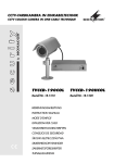
HOCHAUFLÖSENDE
FARBKAMERA
HIGH-RESOLUTION COLOUR CAMERA
TVCCD-187HCOL
Best.-Nr. 18.2480
BEDIENUNGSANLEITUNG
INSTRUCTION MANUAL
MODE D’EMPLOI
ISTRUZIONI PER L’USO
D
A
CH
GB
Vor der Installation …
Wir wünschen Ihnen viel Spaß mit Ihrem neuen Gerät von MONACOR.
Bitte lesen Sie diese Bedienungsanleitung vor dem Betrieb gründlich
durch. Nur so lernen Sie alle Funktionsmöglichkeiten kennen, vermeiden Fehlbedienungen und schützen Ihr Gerät vor eventuellen Schäden
durch unsachgemäßen Gebrauch. Heben Sie die Anleitung für ein
späteres Nachlesen auf.
Der deutsche Text beginnt auf Seite 4.
Prior to the installation …
We hope you will enjoy using your new MONACOR unit. Please read
these operating instructions carefully prior to operating the unit. Thus,
you will get to know all functions of the unit, operating errors will be
prevented, and the unit will be protected against any damage caused
by improper use. Please keep the operating instructions for later use.
The English text starts on page 18.
F
B
CH
I
Avant toute installation …
Nous vous souhaitons beaucoup de plaisir à utiliser votre nouvel
appareil MONACOR. Lisez ce mode dʼemploi entièrement avant toute
utilisation. Uniquement ainsi, vous pourrez apprendre lʼensemble des
possibilités de fonctionnement de lʼappareil, éviter toute manipulation
erronée et protéger lʼappareil de dommages éventuels engendrés par
une utilisation inadaptée. Conservez la notice pour pouvoir vous y
reporter ultérieurement.
La version française se trouve page 32.
Prima dellʼinstallazione …
Vi auguriamo buon divertimento con il vostro nuovo strumento di
MONACOR. Leggete attentamente le istruzioni prima di mettere in
funzione lʼapparecchio. Solo così potete conoscere tutte le funzionalità,
evitare comandi sbagliati e proteggere lʼapparecchio da eventuali danni
in seguito ad un uso improprio. Conservate le istruzioni per poterle
consultare anche in futuro.
Il testo italiano inizia a pagina 46.
2
1
2
3
3
7
3
4
6
5
b
8
c
c
a
12
b
10
9
13
11
3
D
A
Auf der ausklappbaren Seite 3 finden Sie alle beschriebenen
Bedienelemente und Anschlüsse.
CH
Inhalt
1
Übersicht der Bedienelemente und Anschlüsse . . . . . . . . . . . . 5
2
Wichtige Hinweise für den Gebrauch . . . . . . . . . . . . . . . . . . . . 5
3
Einsatzmöglichkeiten . . . . . . . . . . . . . . . . . . . . . . . . . . . . . . . . 6
4
Montage . . . . . . . . . . . . . . . . . . . . . . . . . . . . . . . . . . . . . . . . . . 6
5
Inbetriebnahme . . . . . . . . . . . . . . . . . . . . . . . . . . . . . . . . . . . . . 7
5.1
Anschluss . . . . . . . . . . . . . . . . . . . . . . . . . . . . . . . . . . . . . . . . . 7
5.2
Kamera ausrichten und Objektiv einstellen . . . . . . . . . . . . . . . 8
6
Einstellungen im Bildschirmmenü . . . . . . . . . . . . . . . . . . . . . . . 8
6.1
LENS – Objektiv . . . . . . . . . . . . . . . . . . . . . . . . . . . . . . . . . . . . 9
6.2
SHUTTER – elektronischer Verschluss . . . . . . . . . . . . . . . . . . 9
6.3
WHITE BAL. – Weißabgleich . . . . . . . . . . . . . . . . . . . . . . . . . 10
6.4
BLC – Gegenlichtkompensation . . . . . . . . . . . . . . . . . . . . . . . 11
6.5
AGC – Verstärkungsregelung . . . . . . . . . . . . . . . . . . . . . . . . . 11
6.6
DNR – Rauschunterdrückung . . . . . . . . . . . . . . . . . . . . . . . . . 11
6.7
SENS-UP – Erhöhung der Lichtempfindlichkeit . . . . . . . . . . . 12
6.8 SPECIAL – Aufrufen der 2. Menüseite . . . . . . . . . . . . . . . . . . 12
6.8.1 CAMERA TITLE – Kameranamen einblenden . . . . . . . . . . 13
6.8.2 DAY/ NIGHT – Umschaltung Tagbetrieb / Nachtbetrieb . . . . 14
6.8.3 SYNC – Synchronisation . . . . . . . . . . . . . . . . . . . . . . . . . . . 14
6.8.4 CAM. ID – Steuerung über die RS-485-Schnittstelle . . . . . 14
6.8.5 PRIVACY – Privatzonenabschattung . . . . . . . . . . . . . . . . . 15
6.8.6 MIRROR – Bildspiegelung . . . . . . . . . . . . . . . . . . . . . . . . . 16
6.8.7 DZOOM – Digitaler Zoom . . . . . . . . . . . . . . . . . . . . . . . . . . 16
6.8.8 SHARPNESS – Bildschärfe . . . . . . . . . . . . . . . . . . . . . . . . 16
6.8.9 RESET – Zurücksetzen aller Einstellungen . . . . . . . . . . . . 16
7
4
Technische Daten . . . . . . . . . . . . . . . . . . . . . . . . . . . . . . . . . . 17
1 Übersicht der Bedienelemente und Anschlüsse
D
1 Montagerahmen zur Befestigung an Wand oder Decke
A
2 Kamerahalter zur Befestigung am Montagerahmen (1)
CH
3 Feststellschrauben des Kamerahalters (2): zum Drehen, Schwenken oder Neigen der Kamera die entsprechende Schraube lösen
und nach dem Ausrichten der Kamera wieder festziehen
4 Befestigungsschraube für das Sonnendach (5)
5 Sonnendach
6 Schraubdeckel der Anschlussbuchse für die Fernbedienung (9)
7 Mini-DIN-Stecker zum Anschluss der Fernbedienung an die Kamera [Anschlussbuchse unter dem Schraubdeckel (6)]
8 zusätzlicher BNC-Videoausgang (z. B. für den Anschluss eines
kleinen Testmonitors)
9 Fernbedienung mit den 5 Bedientasten:
a) SET Aufrufen/Verlassen von Bildschirmmenü-Seiten und Bestätigen bestimmter Menüeinstellungen
b) , im Bildschirmmenü: Anwahl von Menüpunkten
Menü nicht aufgerufen: Fokuseinstellung
c) , im Bildschirmmenü: Änderung von Menüeinstellungen
Menü nicht aufgerufen: Zoomeinstellung ( = Brennweite verkürzen, = Brennweite verlängern)
10 BNC-Videoausgang
11 RS-485-Schnittstelle zur Fernsteuerung der Zoom- und Fokus-Einstellungen über ein Steuergerät
12 Anschlussstecker für die Stomversorgung (12 V
oder 24 V~)
13 Adapter zum Verbinden der Stromquelle mit dem Stromversorgungsstecker (12)
2 Wichtige Hinweise für den Gebrauch
Die Kamera entspricht allen erforderlichen Richtlinien der EU und ist
deshalb mit
gekennzeichnet.
G
Schützen Sie die Kamera vor extremen Temperaturen (zulässiger
Einsatztemperaturbereich -10 °C bis +50 °C).
5
D
A
CH
G
Das Kameragehäuse ist wetterfest, jedoch nicht absolut wasserdicht. Tauchen Sie darum die Kamera nicht in Wasser ein.
G Das Objektiv muss vor direkter Sonneneinstrahlung geschützt sein,
da sonst der Bildabtaster beschädigt werden kann.
G Verwenden Sie zum Reinigen keine aggressiven Reinigungsmittel
oder Chemikalien.
G Wird die Kamera zweckentfremdet, nicht richtig installiert, falsch bedient oder nicht fachgerecht repariert, kann keine Haftung für daraus
resultierende Sach- oder Personenschäden und keine Garantie für
die Kamera übernommen werden.
Soll die Kamera endgültig aus dem Betrieb genommen werden, übergeben Sie sie zur umweltgerechten Entsorgung
einem örtlichen Recyclingbetrieb.
3 Einsatzmöglichkeiten
Diese hochauflösende Farbkamera mit Variofocal-Objektiv ist speziell
für den Einsatz in Video-Überwachungsanlagen (CCTV) konzipiert und
für die Decken- oder Wandmontage geeignet. Sie verfügt über ein
wetterfestes Gehäuse (IP 67) und über 30 IR-LEDs, die sich abhängig
von der Umgebungshelligkeit automatisch ein- und ausschalten.
Über ein Bildschirmmenü bietet die Kamera umfangreiche Einstellmöglichkeiten (z. B. manueller oder automatischer Weißabgleich, automatische Umschaltung zwischen Tag- und Nachtbetrieb, Bildspiegelung, 8-facher Digital-Zoom, Privatzonenabschattung etc). Das Menü
ist über die mitgelieferte Fernbedienung einstellbar.
4 Montage
Um die optimale Montagestelle festzustellen, sollte ein Probebetrieb
erfolgen. Dazu die Kamera vorläufig in Betrieb nehmen ( Kapitel 5).
1) Soll die Kamera ohne Sonnendach (5) betrieben werden, zum Abnehmen des Dachs dessen Befestigungsschraube (4) abschrauben.
2) Den Montagerahmen (1) mit den 4 Kreuzschlitzschrauben an der
Wand oder der Decke festschrauben.
3) Den Kamerahalter (2) mit den 4 Innensechskant-Schrauben am
Montagerahmen befestigen. Das Anschlusskabel durch eine Öff6
nung in der Wand/Decke oder durch einen der beiden Kabeldurchlässe am Sockel des Halters ( Abbildung, Seite 3) führen. Bei
einer Außenmontage an einer Wand muss der verwendete Kabeldurchlass nach unten zeigen und der andere abgedichtet werden,
damit kein Niederschlag in die Halterung gelangen kann.
D
A
CH
Bitte beachten: Die Anschlüsse (10) – (12) und der Leitungsverteiler des Kabels sind nicht wetterfest. Bei einer Außeninstallation
müssen sie entsprechend geschützt werden.
5 Inbetriebnahme
5.1 Anschluss
1) Auf der Kamerarückseite befindet sich unter einem Deckel (6) die
Buchse zum Anschluss der Fernbedienung (9). Mit der Fernbedienung werden die Zoom- und Fokuseinstellungen sowie die Einstellungen im Bildschirmmenü ( Kapitel 6) durchgeführt. Den Deckel
mithilfe einer Münze oder eines Schraubendrehers abschrauben und
die Fernbedienung über ihren Mini-DIN-Stecker (7) anschließen.
2) Den BNC-Videoausgang (10) über ein 75-Ω-Koaxialkabel mit dem
Videoeingang des nachfolgenden Geräts (z. B. Monitor, KameraUmschalter) verbinden. Bei einer Kabellänge von über 100 m sollte
zum Ausgleich von Pegelverlusten durch das Kabel ein Videoverstärker zwischen Kamera und Kabel geschaltet werden.
Bei angeschlossener Fernbedienung kann der zusätzliche BNCVideoausgang (8) am Fernbedienungskabel genutzt werden (z. B.
um für die Installation einen kleinen Testmonitor anzuschließen).
3) Die Zoom- und Fokuseinstellungen lassen sich statt über die Fernbedienung auch über die RS-485-Schnittstelle durchführen, z. B.
von einem Computer oder Steuerpult aus. Es wird das Protokoll
PELCO-D verwendet, die Übertragungsrate ist einstellbar ( Kapitel 6.8.4). Die Leitungen RS-485- und RS-485+ (11) mit den entsprechenden Kontakten am Steuergerät verbinden.
4) Als Stromversorgung kann ein stabilisiertes Netzgerät mit 12 V
oder ein Transformator mit 24 V~ verwendet werden. Die Stromaufnahme beträgt max. 800 mA bei 12 V bzw. max. 460 mA bei
24 V~. Die Stromquelle über den beiliegenden Adapter (13) mit dem
7
D
A
CH
zweipoligen Stecker (12) verbinden. Sobald die Betriebsspannung
anliegt, ist die Kamera eingeschaltet.
VORSICHT
Bei Dunkelheit schalten die Infrarot-LEDs ein. Blicken Sie nie aus der Nähe direkt in die eingeschalteten LEDs. Obwohl das Infrarotlicht unsichtbar ist,
kann es Augenschäden verursachen.
5.2 Kamera ausrichten und Objektiv einstellen
Den Monitor, auf dem die Einstellungen überprüft werden sollen, einschalten und die Kamera auf den Überwachungsbereich ausrichten:
zum Drehen, Neigen und Schwenken der Kamera die Feststellschrauben (3) für die entsprechenden Bewegungsachsen lösen (passende
Schlüssel liegen bei) und nach dem Ausrichten wieder festdrehen.
Die Pfeiltasten der Fernbedienung (9) dienen als Zoom- und FokusTasten: Mit den Tasten und (c) den Bildausschnitt einstellen ( =
Brennweite verkürzen, = Brennweite verlängern) und mit den Tasten
und (b) das Bild scharf stellen. (Hinweis: Die Zoom-/Fokuseinstellung ist auch über die RS-485-Schnittstelle möglich Kapitel 5.1.)
6 Einstellungen im Bildschirmmenü
Einstellungen im zweiseitigen Bildschirmmenü werden über die Fernbedienung (9) durchgeführt. Zum Aufruf des Menüs die Taste SET (a)
drücken. Die 1. Menüseite SETUP wird eingeblendet:
SETUP
LENS
SHUTTER
WHITE BAL.
BACKLIGHT
AGC
DNR
SENS-UP
SPECIAL↵
EXIT
AUTO↵
———
ATW↵
OFF
MIDDLE↵
LOW
OFF
Mit der Taste oder (b) den Menüpunkt wählen. Mit der Taste oder (c) eine Einstellung ändern. Steht ein Pfeil ↵ hinter einem
8
Menüpunkt oder einer Einstelloption, kann für weitere Einstellungen mit
der Taste SET (a) in ein Untermenü gewechselt werden. Zum Verlassen eines Untermenüs die Taste SET drücken.
Zum Verlassen des Bildschirmmenüs die Zeile EXIT anwählen und
mit der Taste SET bestätigen. Das Menü blendet sich auch automatisch aus, wenn für ca. 1 Minute keine Taste gedrückt wird.
D
A
CH
6.1 LENS – Objektiv
AUTO↵
automatische Blendenregelung – Grundeinstellung für das
verwendete Objektiv;
im Untermenü kann mit dem Wert BRIGHTNESS der Referenzwert für die Regelung eingestellt werden (höherer
Wert = helleres Bild)
MANUAL
manuelle Blendeneinstellung
(Wird bei gewählter Option MANUAL die Taste SET gedrückt, erscheint das Untermenü MANUAL IRIS: der Wert
LEVEL = 255 im Untermenü sollte nicht verändert werden.)
6.2 SHUTTER – elektronischer Verschluss
Der elektronische Verschluss (shutter) bestimmt die Belichtungszeit
des CCD-Bildabtasters. Je kürzer die Verschlusszeit, desto dunkler
das Bild und desto besser die Wiedergabe von schnellen Bewegungen.
Hinweis: Die verfügbaren Einstelloptionen für SHUTTER hängen von der Einstellung des Menüpunktes LENS (Kapitel 6.1) ab:
Ist für LENS die Einstellung AUTO↵ gewählt, kann für SHUTTER zwischen „ – – – “
und FLK umgeschaltet werden. Ist für LENS die Einstellung MANUAL gewählt, kann
für SHUTTER zwischen ESC↵ , MANUAL↵ und FLK umgeschaltet werden.
— — —
keine Einstellung möglich
FLK
voreingestellte feste Verschlusszeit zum Vermeiden von
Bildflimmern, das bei Einsatz von Lichtquellen auftreten
kann, die mit 50-Hz-Wechselspannung betrieben werden
ESC↵
automatische Regelung der Verschlusszeit;
im Untermenü kann mit dem Wert BRIGHTNESS der Referenzwert für die Regelung eingestellt werden (höherer
Wert = helleres Bild)
MANUAL↵ feste Verschlusszeit einstellbar;
im Untermenü sind verschiedene Verschlusszeiten im Be9
D
reich 1⁄ 50 bis 1⁄ 120 000 Sekunde wählbar; die längste Verschlusszeit kann um den Faktor ×2 ... ×128 erhöht werden:
ausgehend von der Einstellung 1⁄ 50 Sekunde die Taste so oft drücken bis der gewünschte Faktor gewählt ist
– mit höherem Faktor verringert sich allerdings auch die
Bildabtastrate entsprechend
A
CH
6.3 WHITE BAL. – Weißabgleich
Der Weißabgleich dient der Anpassung der Kamera an die Farbtemperatur verschiedener Lichtquellen.
Farbtemperaturen von verschiedenen Lichtquellen:
Glühlampe
Leuchtstofflampe
Sonnenlicht
Tageslicht bei klarem blauen Himmel
ATW↵
2 800 – 3 200 K
4 000 – 5 000 K
> 5 000 K
> 10 000 K
automatische Anpassung bei wechselnder Beleuchtung im
Farbtemperaturbereich 1800 – 10 500 K (z. B. bei Tageslicht
oder bei Verwendung besonderer Lichtquellen wie Natriumdampflampen);
im Untermenü kann zwischen zwei Modi gewählt werden:
OUTDOOR (für Außeneinsätze) und INDOOR (für Innenräume)
Hinweis: Bei folgenden Bedingungen könnte der Modus ATW nicht
optimal funktionieren:
1. wenn die Umgebung des zu überwachenden Objekts eine sehr
hohe Farbtemperatur aufweist (z. B. klarer Himmel, Sonnenuntergang),
2. wenn die Umgebung des zu überwachenden Objekts dunkel ist,
3. wenn die Kamera direkt auf eine Leuchtstofflampe gerichtet ist
oder wenn extrem schwankende Lichtverhältnisse vorherrschen.
In diesem Fall den Modus AWC wählen.
AWC↵
halbautomatischer Weißabgleich: In der Einsatzumgebung
ein Blatt Papier vor das Objektiv halten und die Taste SET
drücken, die Kamera führt dann einen Weißabgleich, angepasst an die aktuellen Lichtverhältnisse, durch. Bei Änderung der Lichtverhältnisse den Weißabgleich wiederholen.
MANUAL↵ manueller Weißabgleich;
im Untermenü ist der Anteil für Rot (RED) und Blau (BLUE)
getrennt einstellbar.
10
6.4 BLC – Gegenlichtkompensation
Die Gegenlichtkompensation (BLC = backlight compensation) dient
dazu, Objekte aufzuhellen, die im Gegenlicht überwacht werden sollen
und durch die Helligkeitsregelung zu dunkel und kontrastarm dargestellt würden.
OFF
BLC ausgeschaltet
HIGH
starke Gegenlichtkompensation (bis zu 42 dB Verstärkung)
MIDDLE
mittlere Gegenlichtkompensation (bis zu 30 dB Verstärkung)
LOW
leichte Gegenlichtkompensation (bis zu 18 dB Verstärkung)
D
A
CH
6.5 AGC – Verstärkungsregelung
Bei schwacher Beleuchtung wird das Videosignal bei eingeschalteter
Verstärkungsregelung (AGC = automatic gain control) entsprechend
verstärkt. Ist die AGC eingeschaltet, kann im Untermenü über den Wert
BRIGHTNESS der Verstärkungsgrad eingestellt werden. Eine hohe
Verstärkung erhöht die Bildhelligkeit, bewirkt aber auch ein stärkeres
Bildrauschen.
OFF
AGC ausgeschaltet (Verstärkung fest auf 6 dB)
HIGH↵
großer Regelbereich (6 – 42 dB)
MIDDLE↵ mittlerer Regelbereich (6 – 30 dB)
LOW↵
kleiner Regelbereich (6 – 18 dB)
6.6 DNR – Rauschunterdrückung
Die Funktion DNR (= digital noise reduction) reduziert das bei schwacher Beleuchtung und hoher Verstärkung zunehmende Rauschen. Ein
Erhöhen der Rauschunterdrückung bewirkt jedoch auch ein Zunehmen des Geisterbild-Effekts.
OFF
DNR ausgeschaltet
HIGH
hohe Rauschunterdrückung.
MIDDLE
mittlere Rauschunterdrückung
LOW
leichte Rauschunterdrückung
Hinweis: Die DNR-Funktion ist nicht verfügbar (Anzeige – – – ), wenn die Verstärkungsregelung AGC (Kapitel 6.5) ausgeschaltet ist.
11
D
6.7 SENS-UP – Erhöhung der Lichtempfindlichkeit
A
Die Funktion SENS-UP dient zur Erhöhung der Lichtempfindlichkeit
bei schwachen Lichtverhältnissen. Die Kamera stellt bei schlechter
Ausleuchtung automatisch eine längere Belichtungszeit ein.
CH
OFF
Funktion ausgeschaltet
AUTO↵
Funktion eingeschaltet;
im Untermenü kann der max. Faktor (×2 ... ×128) für die
Erhöhung der Belichtungszeit eingestellt werden; ein höherer Faktor führt zu einem helleren Bild, bewirkt jedoch
auch ein Zunehmen von Nachzieh-Effekten bei bewegten
Objekten
Hinweise:
1. Die Funktion SENS-UP ist nicht verfügbar (Anzeige – – – ), wenn für den
Menüpunkt SHUTTER (Kapitel 6.2) die Option FLK oder MANUAL↵ eingestellt ist
oder wenn die Verstärkungsregelung AGC (Kapitel 6.5) ausgeschaltet ist.
2. Wird ein höherer Faktor eingestellt, während die Funktion SENS-UP aktiv ist,
können Rauschen und Flecken im Bild auftreten. Dies ist keine Funktionsstörung.
6.8 SPECIAL – Aufrufen der 2. Menüseite
Nach dem Anwählen des Menüpunkts SPECIAL und Bestätigen mit
der Taste SET wird die 2. Menüseite eingeblendet, auf der weitere
Funktionen eingestellt werden können.
SPECIAL
CAMERA TITLE
DAY/NIGHT
SYNC
CAM. ID↵
PRIVACY
MIRROR
DZOOM
SHARPNESS
RESET
RETURN↵
OFF
COLOR
INT
OFF
OFF
OFF
ON↵
Um wieder auf die 1. Menüseite zurückzukehren, die Zeile RETURN
anwählen und mit der Taste SET bestätigen.
12
6.8.1 CAMERA TITLE – Kameranamen einblenden
OFF
keine Einblendung des Kameranamens
ON↵
Einblendung des Kameranamens
D
A
CH
1) Ist die Einstellung ON↵ gewählt, mit der Taste SET in das folgende
Untermenü CAMERA TITLE wechseln:
CAMERA TITLE
ABCDEFGHIJKLM
NOPQRSTUVWXYZ
abcdefghijklm
nopqrstuvwxyz
-. O123456789
In der untersten Zeile befinden sich
15 Felder zur Eingabe von Zeichen
aus dem darüber liegenden Zeichensatz. Das erste Zeichen des Zeichensatzes und das erste Eingabefeld sind angewählt (blau markiert).
CLR POS END
---------------
2) Mit den Tasten , , und das Zeichen für das erste Eingabefeld auswählen und mit der Taste SET bestätigen. Das gewählte
Zeichen erscheint im ersten Eingabefeld und das zweite Eingabefeld ist angewählt. Das Zeichen für das zweite Eingabefeld auswählen und bestätigen usw.
3) Soll ein Zeichen korrigiert werden, kann über die Pfeilsymbole und das jeweilige Eingabefeld angewählt werden: Mit den Tasten
, , und den Pfeil (ein Feld vorspringen) oder den Pfeil (ein Feld zurückspringen) anwählen und zum Bestätigen die Taste
SET drücken. Dann mit den Tasten , , und das neue Zeichen anwählen und durch Drücken der Taste SET das alte Zeichen
mit dem neuen überschreiben.
Soll der gesamte Name gelöscht werden, mit den Tasten , , und CLR anwählen und zum Bestätigen die Taste SET drücken.
4) Um die Position des Kameranamens im Bild festzulegen, mit den
Tasten , , und POS anwählen und zum Bestätigen die
Taste SET drücken. Das Untermenü CAMERA TITLE blendet sich
aus und der Kameraname erscheint links oben auf dem Bildschirm.
Den Namen mit den Tasten , , und an die gewünschte Position bewegen und diese mit der Taste SET bestätigen. Das Untermenü CAMERA TITLE blendet sich wieder ein.
5) Zum Verlassen des Untermenüs mit den Tasten , , und END anwählen und zum Bestätigen die Taste SET drücken.
13
D
A
CH
6.8.2 DAY/ NIGHT – Umschaltung Tagbetrieb / Nachtbetrieb
COLOR immer Farbmodus, IR-Sperrfilter ist aktiviert
BW
immer Schwarzweiß-Modus, IR-Sperrfilter ist deaktiviert
AUTO
automatische Umschaltung zwischen Tagbetrieb (Farbmodus)
und Nachtbetrieb (Schwarzweiß-Modus) in Abhängigkeit von
der Helligkeit der Umgebung: Bei eintretender Dunkelheit
wechselt die Kamera auf S/W-Wiedergabe und das IR-Sperrfilter wird motorisch weggeschwenkt, bei ausreichender Helligkeit bewegt sich das IR-Sperrfilter wieder vor den CCD-Chip
und die Kamera wechselt zurück auf Farbwiedergabe. Die Verzögerungszeit für die Umschaltung beträgt 3 bis 4 Sekunden.
Hinweis: Wird die Kamera bei starkem, unregelmäßig aufflackerndem
IR-Licht auf die Betriebsart AUTO umgestellt, können Funktionsstörungen des IR-Sperrfilters auftreten.
6.8.3 SYNC – Synchronisation
Wird die Kamera über eine 50-Hz-Wechselspannung versorgt, lässt
sich die Art der Bildsynchronisation einstellen:
INT
interne Synchronisation (Bildsynchronisation über einen internen Taktgeber); Standardeinstellung, wenn auf dem angeschlossenen Monitor nur das Bild dieser Kamera betrachtet
werden soll
LL↵
Netzsynchronisation (line lock = Bildsynchronisation über die
Netzfrequenz); durch Netzsynchronisation lassen sich beim
Einsatz mehrerer Kameras, z. B. bei Anlagen mit Kamera-Umschaltern, die Bildsignale der Kameras synchronisieren, sodass bei der Kamera-Umschaltung ein störendes Bildrollen
vermieden wird.
Im Untermenü kann über den Wert PHASE die Phasenlage des
Videosignals korrigiert werden, z. B. wenn die Kamera mit
einer anderen Kamera synchronisiert werden soll, die nicht
von derselben Phase des Netzes versorgt wird.
Bei Gleichspannungsversorgung ist die Kamera fest auf INT eingestellt.
6.8.4 CAM. ID – Steuerung über die RS-485-Schnittstelle
Sollen die Fokus- und Zoom-Einstellungen über die RS-485-Schnittstelle ferngesteuert werden (Anschluss Kapitel 5.1), im Untermenü
CAMERA ID die erforderlichen Einstellungen durchführen: In der Zeile
14
ID NUM der Kamera eine Identifikationsnummer (0 – 255) zuweisen,
damit sie in der Überwachungsanlage adressiert werden kann, und in
der Zeile BAUDRATE die Übertragungsrate (9600 bps, 19 200 bps oder
38 400 bps) einstellen, mit der das Steuergerät arbeitet.
D
A
CH
6.8.5 PRIVACY – Privatzonenabschattung
OFF
Privatzonenabschattung ausgeschaltet
ON↵
Privatzonenabschattung eingeschaltet
Bei eingeschalteter Privatzonenabschattung stehen zum Verdecken
von nicht zu überwachenden Bildzonen vier rechteckige Maskierungsbereiche (AREA1 bis AREA4) zur Verfügung, die sich separat einstellen
lassen:
1
2
3
4
Ist die Einstellung ON↵ gewählt, mit der Taste SET in das folgende Untermenü PRIVACY wechseln:
PRIVACY
AREA SEL
AREA STATE
AREA TONE
TOP
DOWN
LEFT
RIGHT
AREA1
ON
8O
1O
25
2O
4O
Press SET to Return
In der Zeile AREA TONE für alle vier Maskierungsbereiche gemeinsam
den gewünschten Tonwert auswählen: von 1 (schwarz) bis 100 (hellgrau). Dann jeden Maskierungsbereich separat einstellen:
1) In der Zeile AREA SEL den einzustellenden Maskierungsbereich
wählen.
15
D
A
CH
2) Den gewählten Bereich in der Zeile AREA STATE aktivieren (ON)
oder deaktivieren (OFF).
3) Die Größe und Lage des gewählten Bereichs durch Verschieben
der Ränder bestimmen (TOP = oberer Rand, DOWN = unterer Rand,
LEFT = linker Rand, RIGHT = rechter Rand).
6.8.6 MIRROR – Bildspiegelung
OFF
keine Bildspiegelung
VET
vertikale Bildspiegelung
V-H
vertikale und horizontale Bildspiegelung
HOR
horizontale Bildspiegelung
6.8.7 DZOOM – Digitaler Zoom
Wird nach dem Erreichen der 10fachen Vergrößerung über den optischen Zoom der Bildausschnitt noch weiter herangezoomt, schaltet
sich der digitale Zoom dazu. Der Vergrößerungsfaktor des digitalen
Zooms kann zwischen ×2, ×4 und ×8 gewählt werden. Wird OFF gewählt, ist der digitale Zoom ausgeschaltet.
6.8.8 SHARPNESS – Bildschärfe
Die Funktion SHARPNESS dient zur Verbesserung der Bildschärfe.
OFF
Funktion ausgeschaltet
ON↵
Funktion eingeschaltet;
je höher der Wert LEVEL im Untermenü eingestellt wird, desto
schärfer zeichnen sich die Konturen im Bild ab; sehr hohe
Werte können allerdings die Bildqualität beeinträchtigen und
Rauschen erzeugen
6.8.9 RESET – Zurücksetzen aller Einstellungen
Die Funktion RESET löscht alle vom Anwender vorgenommenen Einstellungen und ersetzt sie durch die Werksvorgaben. Die Zeile anwählen und zur Bestätigung die Taste SET drücken. Alle Einstellungen werden sofort zurückgesetzt.
16
7 Technische Daten
Bildaufnehmer: . . . . . . . . . CCD-Chip, 6,35 mm (1/4″)
System: . . . . . . . . . . . . . . . CCIR/ PAL
D
A
CH
Anzahl der Bildpunkte: . . . horizontal 752 × vertikal 582
Auflösung: . . . . . . . . . . . . . 500 Linien (Farbe), 570 Linien (S/ W)
Objektiv: . . . . . . . . . . . . . . Zoom ×10, f = 3,8 – 38 mm (F 1,8 – 2,8)
Blickwinkel: . . . . . . . . . . . . hor. ca. 51,2° (Wide) bis 5,58° (Tele)
vert. ca. 39,3° (Wide) bis 4,27° (Tele)
Infrarotbeleuchtung: . . . . . 30 IR-LEDs, Reichweite 30 m
Mindestbeleuchtung
(IR-LEDs aus): . . . . . . . . . 0,7 Lux bei F 1,8 (Farbe)
Signal-Rausch-Abstand: . . 50 dB (AGC aus)
Elektronischer Verschluss: Flimmerfrei FLK /
Autom. Regelung ESC /
Manuell (×128 ... 1⁄ 50 ... 1⁄ 120 000 Sekunde)
SENS-UP: . . . . . . . . . . . . . ×2 ... ×128, Aus
Weißabgleich: . . . . . . . . . . ATW (1800 – 10 500 K)/AWC/Manuell
Digital-Zoom: . . . . . . . . . . ×2, ×4, ×8, Aus
RS-485-Schnittstelle: . . . . PELCO-D, 9600/19 200/38 400 bps
Videoausgang: . . . . . . . . . 1 Vss/75 Ω, BNC
Einsatztemperaturbereich: -10 °C bis +50 °C
Stromversorgung: . . . . . . . 12 V / max. 800 mA oder
24 V~ / 50 Hz/max. 460 mA
Gehäuseschutzklasse: . . . IP 67
Abmessungen, Gewicht: . . ∅ 82 mm × 145 mm, 1,1 kg
Anschlusskabel: . . . . . . . . 1,2 m
Änderungen vorbehalten.
Diese Bedienungsanleitung ist urheberrechtlich für MONACOR ® INTERNATIONAL
GmbH & Co. KG geschützt. Eine Reproduktion für eigene kommerzielle Zwecke – auch
auszugsweise – ist untersagt.
17
GB
All operating elements and connections described can be found
on the fold-out page 3.
Contents
1
Operating Elements and Connections . . . . . . . . . . . . . . . . . . 19
2
Important Notes . . . . . . . . . . . . . . . . . . . . . . . . . . . . . . . . . . . 19
3
Applications . . . . . . . . . . . . . . . . . . . . . . . . . . . . . . . . . . . . . . 20
4
Installation . . . . . . . . . . . . . . . . . . . . . . . . . . . . . . . . . . . . . . . 20
5
Operation . . . . . . . . . . . . . . . . . . . . . . . . . . . . . . . . . . . . . . . . 21
5.1
Connection . . . . . . . . . . . . . . . . . . . . . . . . . . . . . . . . . . . . . . . 21
5.2
Aligning the camera and adjusting the lens . . . . . . . . . . . . . . 22
6
Settings in the OSD menu . . . . . . . . . . . . . . . . . . . . . . . . . . . 22
6.1
LENS . . . . . . . . . . . . . . . . . . . . . . . . . . . . . . . . . . . . . . . . . . . 23
6.2
SHUTTER . . . . . . . . . . . . . . . . . . . . . . . . . . . . . . . . . . . . . . . . 23
6.3
WHITE BAL. . . . . . . . . . . . . . . . . . . . . . . . . . . . . . . . . . . . . . . 24
6.4
BLC . . . . . . . . . . . . . . . . . . . . . . . . . . . . . . . . . . . . . . . . . . . . . 25
6.5
AGC . . . . . . . . . . . . . . . . . . . . . . . . . . . . . . . . . . . . . . . . . . . . 25
6.6
DNR . . . . . . . . . . . . . . . . . . . . . . . . . . . . . . . . . . . . . . . . . . . . 25
6.7
SENS-UP . . . . . . . . . . . . . . . . . . . . . . . . . . . . . . . . . . . . . . . . 26
6.8 SPECIAL – Activating the second menu page . . . . . . . . . . . . 26
6.8.1 CAMERA TITLE . . . . . . . . . . . . . . . . . . . . . . . . . . . . . . . . . 27
6.8.2 DAY /NIGHT . . . . . . . . . . . . . . . . . . . . . . . . . . . . . . . . . . . . . 28
6.8.3 SYNC . . . . . . . . . . . . . . . . . . . . . . . . . . . . . . . . . . . . . . . . . 28
6.8.4 CAM. ID . . . . . . . . . . . . . . . . . . . . . . . . . . . . . . . . . . . . . . . . 28
6.8.5 PRIVACY . . . . . . . . . . . . . . . . . . . . . . . . . . . . . . . . . . . . . . . 29
6.8.6 MIRROR . . . . . . . . . . . . . . . . . . . . . . . . . . . . . . . . . . . . . . . 30
6.8.7 DZOOM . . . . . . . . . . . . . . . . . . . . . . . . . . . . . . . . . . . . . . . . 30
6.8.8 SHARPNESS . . . . . . . . . . . . . . . . . . . . . . . . . . . . . . . . . . . 30
6.8.9 RESET . . . . . . . . . . . . . . . . . . . . . . . . . . . . . . . . . . . . . . . . 30
7
18
Specifications . . . . . . . . . . . . . . . . . . . . . . . . . . . . . . . . . . . . . 31
1 Operating Elements and Connections
GB
1 Mounting frame for installing the camera on ceilings or walls
2 Camera bracket for fixing the camera to the mounting frame (1)
3 Locking screws of the camera bracket (2): for turning, panning or
tilting the camera, release the corresponding screw and tighten it
again after aligning the camera
4 Locking screw for the sunshield (5)
5 Sunshield
6 Screw cover of the connection jack for the remote control (9)
7 Mini DIN plug for connecting the remote control to the camera
[connection jack below the screw cover (6)]
8 Additional BNC video output (e. g. for connecting a small test
monitor)
9 Remote control with 5 control buttons:
a) SET To activate / deactivate pages of the OSD menu and to
confirm certain menu settings
b) , in the OSD menu: to select menu items
menu not activated: focus setting
c) , in the OSD menu: to change menu settings
menu not activated: zoom setting ( = to reduce the
focal length, = to increase the focal length)
10 BNC video output
11 RS-485 interface for remote control of the zoom and focus settings
via a controller
12 Connection plug for the power supply (12 V
oder 24 V~)
13 Adapter for connecting the power source to the power supply plug
(12)
2 Important Notes
The camera corresponds to all required directives of the EU and is
therefore marked with .
G
Protect the camera against extreme temperatures (admissible ambient temperature range -10 °C to +50 °C).
19
GB
G
The camera housing is weatherproof; however, it is not completely
watertight. Therefore, do not immerse the camera in water.
G
Protect the lens against direct sunlight; otherwise the CCD chip may
be damaged.
G
Never use aggressive detergents or chemicals for cleaning the housing.
G
No guarantee claims for the camera and no liability for any resulting
personal damage or material damage will be accepted if the camera
is used for other purposes than originally intended, if it is not correctly
installed or operated, or if it is not repaired in an expert way.
If the camera is to be put out of operation definitively, take it to
a local recycling plant for a disposal which is not harmful to the
environment.
3 Applications
This high-resolution colour camera with zoom lens is specially designed for applications in video surveillance systems (CCTV). It is
suited for installation on ceilings or walls. The camera is equipped with
a weatherproof housing (IP 67) and with 30 IR LEDs which will automatically be activated / deactivated depending on the ambient light.
Via an OSD menu, the camera offers extensive setting possibilities
(e. g. manual / automatic white balance, automatic switchover between
day /night mode, image inversion, 8-fold digital zoom, privacy masking,
etc.). The menu is adjustable via the remote control provided.
4 Installation
To find the optimum place for installation, a trial operation is recommended. For this purpose, set the camera into preliminary operation
( chapter 5).
1) To operate the camera without sunshield (5), unscrew the corresponding locking screw (4) and remove the sunshield.
2) Fasten the mounting frame (1) to the wall or ceiling by means of the
four recessed head screws.
20
3) Fasten the camera bracket (2) to the mounting frame by means of
the four hexagon socket screws. Guide the connection cable
through an opening in the wall/ceiling or through one of the two lateral cable inlets in the base of the bracket ( figure, page 3). For
outdoor installation on a wall, position the cable inlet used downwards and seal the other inlet to prevent precipitation from entering
the bracket.
GB
Please note: The connections (10) – (12) and the cable distributor
are not weatherproof. For outdoor installation, protect them accordingly.
5 Operation
5.1 Connection
1) The jack for connecting the remote control (9) is situated below a
cover (6) on the rear side of the camera. With the remote control, the
zoom and focus settings and the settings in the OSD menu ( chapter 6) will be made. Unscrew the cover by means of a coin or a
screwdriver and connect the remote control via its mini DIN plug (7).
2) Connect the BNC video output (10) via a 75 Ω coaxial cable to the
video input of the subsequent unit (e. g. monitor, camera switcher).
With a cable length exceeding 100 m, a video amplifier should be inserted between the camera and the cable to compensate for level
loss caused by the cable.
When the remote control is connected, the additional BNC video
output (8) on the remote control cable can be used (e. g. to connect
a small test monitor for the installation).
3) Instead of the remote control, it will also be possible to use the
RS-485 interface (e. g. from a computer or controller) for the zoom
and focus settings. The protocol PELCO-D will be used, the transmission rate will be adjustable ( chapter 6.8.4). Connect the conductors RS-485- and RS-485+ (11) to the corresponding contacts
on the controller.
4) As a power supply, use a regulated 12 V power supply unit or a
24 V~ transformer. The power consumption will be 800 mA max. at
12 V or 460 mA max. at 24 V~. Connect the power source via the
21
GB
adapter provided (13) to the two-pole plug (12). Once the operating
voltage has been applied, the camera will be switched on.
CAUTION
When darkness falls, the infrared LEDs will be
switched on. Never look directly into the lit LEDs at a
close range. Although the infrared light is invisible, it
may cause eye damage.
5.2 Aligning the camera and adjusting the lens
Switch on the monitor for checking the settings and align the camera to
the surveillance zone: for turning, tilting and panning the camera, release the locking screws (3) for the corresponding axes (matching
screw keys are provided) and fasten them again after aligning.
The arrow buttons of the remote control (9) are used as zoom and
focus buttons: Adjust the image section with the buttons and (c)
[ = to reduce the focal length, = to increase the focal length] and
focus the image with the buttons and (b). (Note: Zooming /
focussing will also be possible via the RS-485 interface chapter 5.1.)
6 Settings in the OSD Menu
Settings in the two-page OSD menu will be made via the remote control (9). To activate the menu, press the button SET (a). The first menu
page SETUP will appear:
SETUP
LENS
SHUTTER
WHITE BAL.
BACKLIGHT
AGC
DNR
SENS-UP
SPECIAL↵
EXIT
AUTO↵
———
ATW↵
OFF
MIDDLE↵
LOW
OFF
Select the menu item with the button or (b). Change a setting with
the button or (c). An arrow ↵ behind a menu item or a setting op22
tion means that further settings will be available in a submenu when
the button SET (a) is pressed. To exit a submenu, press the button SET.
To exit the OSD menu, select the line EXIT and press the button
SET to confirm. The menu will also disappear automatically after approximately one minute if no button is pressed.
GB
6.1 LENS
AUTO↵
automatic iris setting – basic setting for the lens used;
in the submenu, the reference value for the control will be
adjusted with the value BRIGHTNESS (the higher the value,
the brighter the image)
MANUAL
manual iris setting
(If the button SET is pressed while the option MANUAL is selected, the submenu MANUAL IRIS will appear: the value
LEVEL = 255 in the submenu should not be modified.)
6.2 SHUTTER
The electronic shutter will define the exposure time of the CCD image
sensor. The shorter the shutter time, the darker the picture and the better the reproduction of fast movements.
Note: The setting options available for SHUTTER depend on the setting of the
menu item LENS (chapter 6.1):
If the setting AUTO↵ has been selected for LENS, it will be possible to switch over
between “ – – – ” and FLK for SHUTTER. If the setting MANUAL has been selected
for LENS, it will be possible to switch over between ESC↵ , MANUAL↵ and FLK for
SHUTTER.
— — —
no setting possible
FLK
preset fixed shutter time to prevent flickering which may
occur when using light sources operated with a 50 Hz AC
voltage
ESC↵
automatic control of shutter time;
in the submenu, the reference value for the control will be
adjusted with the value BRIGHTNESS (the higher the value,
the brighter the image)
MANUAL↵ fixed shutter time to be selected;
in the submenu, several shutter times will be available in
the range of 1⁄ 50 to 1⁄ 120 000 second; it will be possible to in23
GB
crease the longest shutter time by factor ×2 ... ×128:
starting from the setting 1⁄ 50 second, press the button repeatedly until the desired factor is selected – however, a
higher factor will reduce the sampling rate accordingly
6.3 WHITE BAL.
The white balance is used to adapt the camera to the colour temperature of different light sources.
Colour temperature of different light sources:
Incandescent lamp
Fluorescent lamp
Sunlight
Daylight with a clear blue sky
ATW↵
2 800 – 3 200 K
4 000 – 5 000 K
> 5 000 K
> 10 000 K
automatic adaptation with varying lighting in the colour temperature range 1800 – 10 500 K (e. g. for daylight or when
using special light sources such as sodium vapour lamps)
in the submenu, two modes will be available:
OUTDOOR and INDOOR
Note: In the following situations, the mode ATW may fail to function in
an optimum way:
1. if the area surrounding the object to be monitored has a very high
colour temperature (e.g. clear sky, sunset),
2. if the area surrounding the object to be monitored is dark,
3. if the camera is directly turned towards a fluorescent lamp or if
there are extreme light fluctuations.
In this case, select the mode AWC.
AWC↵
semiautomatic white balance: In the zone of application,
hold a sheet of paper in front of the lens and press the button SET; the camera will perform a white balance adapted
to the current lighting conditions. If the lightings conditions
change, repeat the white balance.
MANUAL↵ manual white balance;
In the submenu, the proportions of RED and BLUE will be
adjusted separately.
24
GB
6.4 BLC
The backlight compensation (BLC) is used to illuminate objects which
are to be monitored in the backlight and which would appear too dark
or low in contrast with the brightness control.
OFF
BLC deactivated
HIGH
high backlight compensation (amplification up to 42 dB)
MIDDLE
average backlight compensation (amplification up to 30 dB)
LOW
low backlight compensation (amplification up to 18 dB)
6.5 AGC
With poor lighting, the video signal will be amplified accordingly when
the automatic gain control (AGC) has been activated. If the AGC has
been activated, adjust the rate of amplification in the submenu via the
value BRIGHTNESS. A high amplification will increase the brightness of
the image, but will also cause a higher image noise.
OFF
AGC deactivated (fixed amplification: 6 dB)
HIGH↵
wide control range (6 – 42 dB)
MIDDLE↵ average control range (6 – 30 dB)
LOW↵
narrow control range (6 – 18 dB)
6.6 DNR
The digital noise reduction (DNR) will reduce the noise which will increase with poor lighting and high amplification. However, when the
digital noise reduction is increased, the ghost image effect will also be
increased.
OFF
DNR deactivated
HIGH
high noise reduction
MIDDLE
average nose reduction
LOW
low noise reduction
Note: The DNR function will not be available (indication – – – ) if the AGC has been
deactivated (chapter 6.5).
25
GB
6.7 SENS-UP
The function SENS-UP is used to increase the sensitivity to light in
poor lighting conditions. With a low lighting level, the camera will automatically increase the exposure time.
OFF
function deactivated
AUTO↵
function activated;
in the submenu, the maximum factor (×2 ... ×128) for increasing the exposure time is adjustable; a higher factor will
result in a brighter image, however, it will also increase
after-image effects with moving objects
Notes:
1. The function SENS-UP is not available (indication – – – ) if the option FLK or
MANUAL↵ has been adjusted for the menu item SHUTTER (chapter 6.2) or if the
automatic gain control (AGC) [chapter 6.5] has been deactivated.
2. If a higher factor is adjusted while the function SENS-UP is activated, the image
may show noise and spots. This is not a malfunction.
6.8 SPECIAL – Activating the second menu page
After the menu item SPECIAL has been selected and the button SET
has been pressed to confirm, the second menu page will appear offering further functions.
SPECIAL
CAMERA TITLE
DAY/NIGHT
SYNC
CAM. ID↵
PRIVACY
MIRROR
DZOOM
SHARPNESS
RESET
RETURN↵
OFF
COLOR
INT
OFF
OFF
OFF
ON↵
To return to the first menu page, select the line RETURN and press the
button SET to confirm.
26
GB
6.8.1 CAMERA ID
OFF
no camera name inserted
ON↵
camera name inserted
1) With ON↵ selected, press the button SET to go to the next submenu
CAMERA TITLE:
CAMERA TITLE
ABCDEFGHIJKLM
NOPQRSTUVWXYZ
abcdefghijklm
nopqrstuvwxyz
-. O123456789
In the lower line, you will find 15
fields to enter characters from the
character set above it. The first character of the set and the first input field
are selected (highlighted in blue).
CLR POS END
---------------
2) Select the character for the first input field with the buttons , , and and press the button SET to confirm. The character selected
will appear in the first input field and the second input field is selected. Select the character for the second input field and confirm,
etc.
3) To correct a character, select the corresponding input field via the
arrow symbols and : Select the arrow (to go forward one
field) or the arrow (to go back one field) with the buttons , ,
and , and press the button SET to confirm. Then select the new
character with the buttons , , and and press the button
SET to overwrite the old character with the new one.
To delete the entire name, select CLR with the buttons , , and and press the button SET to confirm.
4) To define the position of the camera name in the image, select POS
with the buttons , , and and press the button SET to confirm. The submenu CAMERA TITLE will disappear and the camera
name will appear on the top left of the screen. Move the name to the
desired position with the buttons , , and and press the button SET to confirm. The submenu CAMERA TITLE will reappear.
5) To exit the submenu, select END with the buttons , , and and press the button SET to confirm.
27
GB
6.8.2 DAY/ NIGHT
COLOR permanent colour mode, IR suppression filter activated
BW
permanent black-and-white mode, IR suppression filter deactivated
AUTO
automatic switchover between day mode (colour mode) and
night mode (B / W mode) depending on the ambient light: When
darkness falls, the camera will switch over to B / W reproduction
and the IR suppression filter will be removed mechanically;
with sufficient lighting, the IR suppression filter will return to its
position in front of the CCD chip and the camera will switch
back to colour reproduction. The delay time for switchover will
be 3 to 4 seconds.
Note: If the camera is set to AUTO mode when there is a powerful IR light
flickering erratically, malfunctions of the IR suppression filter may occur.
6.8.3 SYNC
If the camera is supplied with power via a 50 Hz AC voltage, the type
of image synchronization will be adjustable.
INT
internal synchronization (image synchronization via an internal
pulse generator); standard setting for displaying the image of
this camera only on the monitor connected
LL↵
line lock (image synchronization via the mains frequency);
when several cameras are used (e. g. for systems with camera
switchers), line lock will allow to synchronize the video signals
of these cameras to prevent the images from rolling vertically
when switching between cameras
In the submenu, the phase of the video signal will be corrected
via the value PHASE, e. g. for synchronizing the camera with
another camera not supplied with power from the same phase
of the mains.
With a DC power supply, the fixed setting of the camera will be INT.
6.8.4 CAM. ID
For remote control of focus and zoom settings via the RS-485 interface
(connection chapter 5.1), make the required settings in the submenu CAMERA ID: In the line ID NUM, assign an identification number
(0 – 255) to the camera to allow addressing in the surveillance system,
28
and in the line BAUDRATE, adjust the transmission rate (9600 bps,
19 200 bps or 38 400 bps) of the controller.
GB
6.8.5 PRIVACY
OFF
privacy masking deactivated
privacy masking activated
ON↵
When the privacy masking is activated, four rectangular masking areas
(AREA1 to AREA4), adjustable separately, will be available to mask
image areas not to be monitored:
1
2
3
4
When ON↵ is selected, press the button SET to go to the next submenu
PRIVACY:
PRIVACY
AREA SEL
AREA STATE
AREA TONE
TOP
DOWN
LEFT
RIGHT
AREA1
ON
8O
1O
25
2O
4O
Press SET to Return
In the line AREA TONE, select the desired shade for all four masking
areas together: from 1 (black) to 100 (light grey). Then adjust each
masking area separately:
1) In the line AREA SEL, select the masking area to be adjusted.
2) In the line AREA STATE, activate (ON) or deactivate (OFF) the area
selected.
3) Define the size and the position of the area selected by displacing
its edges (TOP, DOWN, LEFT, RIGHT).
29
GB
6.8.6 MIRROR
OFF
no image inversion
VET
vertical image inversion
V-H
vertical and horizontal image inversion
HOR
horizontal image inversion
6.8.7 DZOOM
When the 10-fold magnification via the optical zoom is reached and the
image is zoomed in further, the digital zoom will be activated. Select the
magnification factor of the digital zoom between ×2, ×4 and ×8. If OFF
is selected, the digital zoom will be deactivated.
6.8.8 SHARPNESS
The function SHARPNESS is used to improve the sharpness of the
image.
OFF
function deactivated
ON↵
function activated
the higher the value LEVEL in the submenu, the sharper the
contours of the image; however, very high values may affect
the image quality and create noise
6.8.9 RESET
The function RESET will delete all user settings and replace them by
the factory settings. Select the line and press the button SET to confirm. All settings will be reset immediately.
30
7 Specifications
GB
Image sensor: . . . . . . . . . . 6.35 mm (1/4″) CCD chip
System: . . . . . . . . . . . . . . . CCIR / PAL
Number of pixels: . . . . . . . hor. 752 × vert. 582
Resolution: . . . . . . . . . . . . 500 lines (colour), 570 lines (B / W)
Lens: . . . . . . . . . . . . . . . . . zoom ×10, f = 3.8 – 38 mm (F 1.8 – 2.8)
Angle of view: . . . . . . . . . . hor. approx. 51.2° (wide) to 5.58° (tele)
vert. approx. 39.3° (wide) to 4.27° (tele)
IR illumination: . . . . . . . . . 30 IR LEDs, range 30 m
Minimum illumination
(IR LEDs off): . . . . . . . . . . 0.7 lux at F 1.8 (colour)
S / N ratio: . . . . . . . . . . . . . . 50 dB (AGC off)
Electronic shutter: . . . . . . . flicker-free FLK /
automatic control ESC /
manual (×128 ... 1⁄ 50 ... 1⁄ 120 000 second)
SENS-UP: . . . . . . . . . . . . . ×2 ... ×128, off
White balance: . . . . . . . . . ATW (1800 – 10 500 K) /AWC / manual
Digital zoom: . . . . . . . . . . . ×2, ×4, ×8, off
RS-485 interface: . . . . . . . PELCO-D; 9600/19 200/38 400 bps
Video output . . . . . . . . . . . 1 Vpp / 75 Ω, BNC
Ambient temperature . . . . -10 °C to +50 °C
Power supply: . . . . . . . . . . 12 V / 800 mA max. or
24 V~ / 50 Hz/460 mA max.
Protection class of housing: IP 67
Dimensions, weight: . . . . . ∅ 82 × 145 mm, 1.1 kg
Connection cable: . . . . . . . 1.2 m
Subject to technical modification.
All rights reserved by MONACOR ® INTERNATIONAL GmbH & Co. KG. No part of this
instruction manual may be reproduced in any form or by any means for any commercial use.
31
F
B
Vous trouverez sur la page 3, dépliable, les éléments et branchements décrits.
CH
Table des matières
1
Eléments et branchements . . . . . . . . . . . . . . . . . . . . . . . . . . . 33
2
Conseils importants dʼutilisation . . . . . . . . . . . . . . . . . . . . . . . 33
3
Possibilités dʼutilisation . . . . . . . . . . . . . . . . . . . . . . . . . . . . . . 34
4
Montage . . . . . . . . . . . . . . . . . . . . . . . . . . . . . . . . . . . . . . . . . 34
5
Fonctionnement . . . . . . . . . . . . . . . . . . . . . . . . . . . . . . . . . . . 35
5.1
Branchement . . . . . . . . . . . . . . . . . . . . . . . . . . . . . . . . . . . . . 35
5.2
Orientation de la caméra et réglage de lʼobjectif . . . . . . . . . . 36
6
Réglages dans le menu écran . . . . . . . . . . . . . . . . . . . . . . . . 36
6.1
LENS – objectif . . . . . . . . . . . . . . . . . . . . . . . . . . . . . . . . . . . . 37
6.2
SHUTTER – obturation électronique . . . . . . . . . . . . . . . . . . . 37
6.3
WHITE BAL. – compensation du blanc . . . . . . . . . . . . . . . . . 38
6.4
BLC – compensation du contre-jour . . . . . . . . . . . . . . . . . . . . 39
6.5
AGC – réglage de lʼamplification . . . . . . . . . . . . . . . . . . . . . . 39
6.6
DNR – élimination du bruit . . . . . . . . . . . . . . . . . . . . . . . . . . . 39
6.7
SENS-UP – augmentation de la sensibilité à la lumière . . . . . 40
6.8 SPECIAL – appel de la page 2 du menu . . . . . . . . . . . . . . . . 40
6.8.1 CAMERA TITTLE – affichage du nom de la caméra . . . . . . 41
6.8.2 DAY NIGHT – commutation fonctionnement jour / nuit . . . . . 42
6.8.3 SYNC – synchronisation . . . . . . . . . . . . . . . . . . . . . . . . . . . 42
6.8.4 CAMERA ID – gestion via lʼinterface RS-485 . . . . . . . . . . . 42
6.8.5 PRIVACY – masquage des zones privées . . . . . . . . . . . . . 43
6.8.6 MIRROR – fonction miroir . . . . . . . . . . . . . . . . . . . . . . . . . . 44
6.8.7 DZOOM – zoom digital . . . . . . . . . . . . . . . . . . . . . . . . . . . . 44
6.8.8 SHARPNESS – netteté de lʼimage . . . . . . . . . . . . . . . . . . . 44
6.8.9 RESET – réinitialisation de tous les réglages . . . . . . . . . . . 44
7
32
Caractéristiques techniques . . . . . . . . . . . . . . . . . . . . . . . . . . 45
F
1 Eléments et branchements
1 Etrier de montage pour fixation au mur ou au plafond
2 Support de caméra pour fixation sur lʼétrier de montage (1)
B
CH
3 Vis de réglage du support de caméra (2) ; desserrez la vis correspondante pour orienter, incliner ou tourner la caméra, une fois le
réglage effectué, revissez la vis
4 Vis de fixation pour le pare soleil (5)
5 Pare soleil
6 Couvercle à vis de la prise de branchement pour la télécommande
(9)
7 Fiche mini DIN mâle pour brancher la télécommande à la caméra
[prise de branchement sous le couvercle (6)]
8 Sortie vidéo BNC supplémentaire (par exemple pour brancher un
petit moniteur test)
9 Télécommande avec 5 touches de commande :
a) SET appeler / quitter les pages du menu écran et confirmer
certains réglages du menu
b) , dans le menu écran : sélection de points du menu
menu non appelé : réglage du focus
c) , dans le menu écran : modification de réglages du menu
menu non appelé : réglage zoom ( = réduction de la
distance focale, = augmentation de la distance focale)
10 Sortie vidéo BNC
11 Interface RS-485 pour gérer à distance les réglages du zoom et du
focus via un contrôleur
12 Prise de branchement pour lʼalimentation (12 V
oder 24 V~)
13 Adaptateur pour relier la source dʼalimentation à la prise alimentation (12)
2 Conseils dʼutilisation importants
La caméra répond à toutes les directives nécessaires de lʼUnion européenne et porte donc le symbole .
G Protégez la caméra de températures extrêmes (plage de température de fonctionnement autorisée : -10 °C à +50 °C).
33
F
B
CH
G
Le boîtier de la caméra est résistant aux intempéries mais nʼest pas
complètement étanche. Ne plongez jamais la caméra dans lʼeau.
G Lʼobjectif doit être protégé du rayonnement direct du soleil sinon la
puce pourrait être endommagée.
G Pour le nettoyage, nʼutilisez pas de produits détergents abrasifs ou
de produits chimiques.
G Nous déclinons toute responsabilité en cas de dommages corporels
ou matériels résultants si la caméra est utilisée dans un but autre que
celui pour lequel elle a été conçue, si elle nʼest pas correctement installée ou utilisée ou si elle nʼest pas réparée par une personne habilitée, de même, la garantie deviendrait caduque.
Lorsque la caméra est définitivement retirée du service, vous
devez la déposer dans une usine de recyclage de proximité
pour contribuer à son élimination non polluante.
3 Possibilités dʼutilisation
Cette caméra couleur haute résolution avec objectif à focale variable
est spécialement conçue pour une utilisation dans des installations de
surveillance vidéo (CCTV) et est adaptée pour un montage au mur ou
au plafond. Elle dispose dʼun boîtier résistant aux intempéries (IP 67)
et de 30 LEDs infrarouges qui sʼallument et sʼéteignent automatiquement en fonction de la luminosité ambiante.
Elle propose différentes possibilités de réglage via le menu écran
(par exemple : compensation automatique ou manuelle du blanc, commutation automatique entre fonctionnement jour et fonctionnement
nuit, fonction miroir, zoom digital ×8, masquage des zones privées etc).
Le menu est réglable via la télécommande livrée.
4 Montage
Pour déterminer lʼendroit optimal de montage, effectuez un test de
fonctionnement, pour ce faire, faites fonctionner la caméra provisoirement ( chapitre 5).
1) Si la caméra doit fonctionner sans pare soleil (5), dévissez la vis de
fixation (4) et retirez le pare soleil.
2) Vissez lʼétrier de montage (1) avec 4 vis à tête creuse au mur ou au
plafond.
34
3) Fixez le support de caméra (2) à lʼétrier de montage avec 4 vis hexagonales. Faites passer le câble de branchement via une ouverture
dans le mur / plafond ou via un des deux passages de câble sur le
socle du support ( schéma, page 3). Pour un montage en extérieur sur un mur, il faut que le passage de câble utilisé soit vers le
bas et que lʼautre passage soit étanchéifié afin quʻaucune précipitation ne puisse pénétrer dans le support.
F
B
CH
Attention : Les branchements (10) – (12) et le répartisseur de câble
ne sont pas étanches ; pour une utilisation en extérieur, ils doivent
être protégés en conséquence.
5 Fonctionnement
5.1 Branchement
1) La prise pour brancher la télécommande (9) se trouve sur la face
arrière de la caméra sous un couvercle (6). Avec la télécommande,
on peut effectuer les réglages de zoom et de focus et les réglages
dans le menu écran ( chapitre 6). Dévissez le couvercle avec une
pièce de monnaie ou un tournevis et branchez la télécommande via
sa fiche mini DIN (7).
2) Reliez la sortie vidéo BNC (10) via un câble coaxial 75 Ω à lʼentrée
vidéo de lʼappareil suivant (par exemple moniteur, sélecteur de caméra). Pour une longueur de câble supérieure à 100 m, il convient
dʼinsérer entre la caméra et le câble un amplificateur vidéo pour
compenser les pertes de niveau générées par le câble.
Lorsque la télécommande est reliée, on peut utiliser la sortie
vidéo BNC supplémentaire (8) sur le câble de la télécommande (par
exemple pour relier un petit moniteur test pour lʼinstallation).
3) Les réglages de zoom et de focus peuvent être effectués via lʼinterface RS-485 au lieu de la télécommande, par exemple depuis
un ordinateur ou un pupitre de commande. Le protocole PELCO-D
est utilisé, le taux de transmission est réglable ( chapitre 6.8.4).
Reliez les câbles RS-485- et RS-485+ (11) aux contacts correspondants sur le contrôleur.
4) Comme alimentation, on peut utiliser un bloc secteur 12 V ou un
transformateur 24 V~. La consommation est de 800 mA max. pour
12 V et de 460 mA max. pour 24 V~. Reliez la source dʼalimenta35
F
B
CH
tion via lʼadaptateur livré (13) à la fiche deux pôles (12). Dès que la
tension de fonctionnement est présente, la caméra est allumée.
ATTENTION
Les LEDs infrarouges sʼallument en cas de pénombre. Ne regardez jamais directement à proximités des
LEDs allumées. Bien que la lumière infrarouge soit
invisible, elle peut générer des troubles de la vision.
5.2 Orientation de la caméra et réglage de lʼobjectif
Allumez le moniteur sur lequel les réglages doivent être vérifiés et
orientez la caméra sur la zone de surveillance : dévissez les vis de réglage (3) pour les axes de mouvements correspondants pour tourner,
incliner et orienter la caméra (clés correspondantes livrées) puis revissez une fois le réglage effectué.
Les touches flèche de la télécommande (9) servent de touches de
zoom et focus : avec les touches et (c ), réglez la section dʼimage
[ = réduction de la distance focale, = augmentation de la distance
focale] et avec les touches et (b), réglez la netteté de lʼimage.
(Conseil : le réglage zoom / focus est également possible via lʼinterface
RS-485, chapitre 5.1).
6 Réglages dans le menu écran
Les réglages dans le menu écran double page sʼeffectuent via la télécommande (9). Pour appeler le menu, appuyez sur la touche SET (a).
La page 1 SETUP sʼaffiche :
SETUP
LENS
SHUTTER
WHITE BAL.
BACKLIGHT
AGC
DNR
SENS-UP
SPECIAL↵
EXIT
AUTO↵
———
ATW↵
OFF
MIDDLE↵
LOW
OFF
Avec la touche ou (b), sélectionnez un point du menu. Avec la
touche ou (c), modifiez un réglage. Si une flèche ↵ se trouve der36
rière un point du menu ou une option de réglage, on peut accéder à un
sous-menu pour dʼautres réglages avec la touche SET (a) enfoncée.
Pour quitter un sous-menu, appuyez sur la touche SET.
Pour quitter le menu écran, sélectionnez la ligne EXIT, confirmez
avec la touche SET. Le menu disparaît automatiquement si aucune
touche nʼest enfoncée pendant 1 minute environ.
F
B
CH
6.1 LENS – objectif
AUTO↵
réglage automatique dʼobjectif - réglage de base pour lʼobjectif utilisé ;
dans le sous-menu, la valeur de référence pour le réglage
est réglée avec la valeur BRIGHTNESS (plus la valeur est
élevée, plus lʼimage est claire)
MANUAL
réglage manuel dʼobjectif
(Si la touche SET est enfoncée lorsque lʼoption MANUAL est
sélectionnée, le sous-menu MANUAL IRIS sʼaffiche : la valeur LEVEL = 255 dans le sous-menu ne doit pas être modifiée.)
6.2 SHUTTER – obturation électronique
Lʼobturation électronique (shutter) détermine la durée dʼexposition de
la puce CCD. Plus la durée dʼobturation est courte, plus lʼimage est
sombre et meilleure est la restitution de mouvements rapides.
Conseil : Les options de réglage disponibles pour SHUTTER dépendent du réglage
du point de menu LENS (chapitre 6.1) :
Si pour LENS, le réglage AUTO↵ est sélectionné, on peut commuter pour SHUTTER entre “ – – – ” et FLK. Si pour LENS, le réglage MANUAL est sélectionné, on
peut commuter pour SHUTTER entre ESC↵ , MANUAL↵ et FLK.
— — —
aucun réglage possible
FLK
temps dʼobturation préréglé fixe pour éviter tout scintillement de lʼimage pouvant apparaître si on utilise des
sources de lumière fonctionnant avec une tension alternative de 50 Hz
ESC↵
réglage automatique de la durée dʼobturation ;
dans le sous-menu, la valeur de référence est réglée pour
le réglage avec la valeur BRIGHTNESS (plus la valeur est
élevée, plus lʼimage est claire)
37
F
B
CH
MANUAL↵ durée dʼobturation réglable
Dans le sous-menu, différentes durées dʼobturation dans la
plage 1⁄ 50 à 1⁄ 120 000 secondes sont sélectionnables : la durée
dʼobturation la plus grande peut augmenter du facteur ×2 ...
×128 : en partant du réglage 1⁄ 50 seconde, appuyez sur la
touche jusquʼà ce que le facteur voulu soit sélectionné
– avec un facteur plus grand, le taux dʼéchantillonnage
diminue cependant.
6.3 WHITE BAL. – compensation du blanc
La compensation du blanc permet dʼadapter la caméra à la température de couleur de différentes sources de lumière.
Températures de couleur de différentes sources de lumière :
lampe à incandescence
lampe fluorescente
lumière du soleil
lumière du jour avec un ciel bleu et clair
ATW↵
2 800 – 3 200 K
4 000 – 5 000 K
> 5 000 K
> 10 000 K
adaptation automatique avec une luminosité changeante
dans une plage de température de couleurs 1800 à 10 500 K
(p. ex. lumière du jour ou utilisation de sources lumineuses
particulières comme des lampes à vapeur de sodium).
Dans le sous-menu, on peut sélectionner entre deux
modes : OUTDOOR (pour des applications en extérieur) et
INDOOR (pour des pièces en intérieur).
Conseil : Le mode ATW pourrait ne pas fonctionner de manière optimale dans les cas suivants :
1. Lorsque lʼenvironnement de lʼobjet à surveiller présente une température de couleur très élevée (par exemple ciel clair, soleil couchant).
2. Lorsque lʼenvironnement de lʼobjet à surveiller est trop sombre.
3. Lorsque la caméra est directement orientée vers une lampe fluorescente ou sʼil y a dʼimportantes fluctuations dʼéclairage.
Dans ce cas, sélectionnez le mode AWC.
AWC↵
38
compensation semi automatique du blanc : tenez une feuillez de papier devant lʼobjectif dans la zone dʼutilisation, appuyez sur la touche SET. La caméra effectue une compensation du blanc en fonction des conditions actuelles dʼéclairage. Lorsque les conditions dʼéclairage sont modifiées,
répétez la compensation du blanc.
MANUAL↵ compensation manuelle du blanc : dans le sous-menu, la
part de rouge (RED) et bleu (BLUE) est réglable séparément.
6.4 BLC – compensation du contre-jour
F
B
CH
La compensation du contre-jour (BLC = backlight compensation) permet dʼéclaircir des objets devant être surveillés en contre-jour et qui
apparaîtraient trop sombres ou pauvres en contraste par le réglage de
luminosité.
OFF
BLC désactivé
HIGH
compensation importante (jusquʼà 42 dB dʼamplification)
MIDDLE
compensation moyenne (jusquʼà 30 dB dʼamplification)
LOW
compensation faible (jusquʼà 18 dB dʼamplification)
6.5 AGC – réglage de lʼamplification
En cas dʼéclairage faible, le signal vidéo est amplifié en conséquence
lorsque le réglage dʼamplification (AGC = automatic gain control) est
activé. Si le réglage dʼamplification AGC est activé, on peut régler dans
le sous-menu le degré dʼamplification via la valeur BRIGHTNESS. Une
amplification importante augmente la luminosité de lʼimage, mais implique également un bruit plus important de lʼimage.
OFF
AGC désactivé (amplification fixe 6 dB)
HIGH
plage de réglage grande (6 – 42 dB)
MIDDLE
plage de réglage moyenne (6 – 30 dB)
LOW
plage de réglage faible (6 – 18 dB)
6.6 DNR – élimination du bruit
La fonction DNR (= digital noise réduction) diminue le bruit croissant
avec un éclairage faible et une amplification élevée. Une augmentation
de lʼélimination du bruit implique cependant une augmentation de lʼeffet image fantôme.
OFF
DNR désactivée
HIGH
élimination importante du bruit
MIDDLE
élimination moyenne du bruit
LOW
élimination faible du bruit
Conseil : La fonction DNR nʼest pas disponible (affichage – – – ) lorsque le réglage
dʼamplification AGC (chapitre 6.5) est désactivé.
39
F
6.7 SENS-UP – augmentation de la sensibilité à la lumière
B
La fonction SENS-UP permet dʼaugmenter la sensibilité à la lumière en
cas de conditions dʼéclairage faibles. La caméra augmente automatiquement la durée dʼexposition en cas de mauvais éclairage.
CH
OFF
fonction désactivée
AUTO↵
fonction activée :
dans le sous-menu, on peut régler le facteur maximum
(×2 ... ×128) pour lʼaugmentation de la durée dʼexposition :
un facteur plus élevé implique une image plus claire, mais
pour des objets se déplaçant, une augmentation des effets
dʼaprès image est notable.
Conseils :
1. La fonction SENS-UP nʼest pas disponible (affichage – – – ) si lʼoption FLK ou
MANUAL↵ est réglée pour le point de menu SHUTTER (chapitre 6.2) ou si le
réglage dʼamplification AGC (chapitre 6.5) est désactivé.
2. Si un facteur supérieur est réglé alors que la fonction SENS-UP est activée,
des bruits et tâches peuvent apparaître sur lʼimage. Ce nʼest pas un dysfonctionnement de la fonction.
6.8 SPECIAL – appel de la page 2 du menu
Une fois le point de menu SPECIAL sélectionné et confirmé avec la
touche SET, la page 2 du menu sʼaffiche, on peut y régler les fonctions
suivantes :
SPECIAL
CAMERA TITLE
DAY/NIGHT
SYNC
CAM. ID↵
PRIVACY
MIRROR
DZOOM
SHARPNESS
RESET
RETURN↵
OFF
COLOR
INT
OFF
OFF
OFF
ON↵
Pour revenir à la première page, sélectionnez la ligne RETURN et confirmez avec la touche SET.
40
6.8.1 CAMERA TITTLE – affichage du nom de la caméra
OFF
aucun affichage du nom de la caméra
ON↵
affichage du nom de la caméra
F
B
CH
1) Si le réglage ON↵ est sélectionné, passez au sous-menu suivant
CAMERA TITLE avec la touche SET :
CAMERA TITLE
ABCDEFGHIJKLM
NOPQRSTUVWXYZ
abcdefghijklm
nopqrstuvwxyz
-. O123456789
Dans la dernière ligne, il y a 15 champs
pour saisir des caractères parmi le
jeu de caractères au-dessus. Le premier caractère du jeu de caractères
et le premier champ de saisie sont
sélectionnés (repérés en bleu).
CLR POS END
---------------
2) Avec les touches , , et , sélectionnez le caractère pour le
premier champ de saisie, confirmez avec la touche SET. Le caractère choisi sʼaffiche dans le premier champ de saisie, le deuxième
champ de saisie est sélectionné. Sélectionnez le caractère pour le
deuxième champ, confirmez et ainsi de suite.
3) Sʼil faut corriger un caractère, sélectionnez le champ correspondant
avec les symboles flèche et ; avec les touches , , et ,
sélectionnez la flèche (pour avancer dʼun champ) ou la flèche (pour reculer dʼun champ), confirmez avec la touche SET. Avec les
touches , , et , sélectionnez le nouveau caractère, en appuyant sur la touche SET, écrasez lʼancien caractère par le nouveau.
Si tout le nom doit être effacé, sélectionnez CLR avec les touches
, , et , confirmez avec la touche SET.
4) Pour déterminer la position du nom de la caméra dans lʼimage, sélectionnez POS avec les touches , , et , confirmez avec la
touche SET. Le sous-menu CAMERA TITLE disparaît, le nom de la
caméra sʼaffiche en haut à gauche sur lʼécran. Déplacez le nom
avec les touches , , et , sur la position souhaitée, confirmez avec SET. Le sous-menu CAMERA TITLE sʼaffiche à nouveau.
5) Pour quitter le sous-menu, sélectionnez END avec les touches ,
, et , confirmez avec SET.
41
F
B
CH
6.8.2 DAY NIGHT – commutation fonctionnement jour / nuit
COLOR mode couleur permanent, filtre suppresseur IR activé
BW
mode noir et blanc permanent, filtre suppresseur IR désactivé
AUTO
commutation automatique entre fonctionnement jour (mode
couleur) et fonctionnement nuit (mode noir et blanc) selon la
luminosité ambiante. Lorsque la pénombre apparaît, la caméra passe sur lecture noir et blanc, le filtre suppresseur dʼinfrarouges est enlevé mécaniquement ; lorsque la luminosité
est suffisante, le filtre se replace devant la puce CCD, la caméra revient sur la lecture couleur. La durée de temporisation
pour la commutation est de 3 à 4 secondes.
Conseil : Si la caméra est réglée sur le mode de fonctionnement AUTO en
cas de lumière infrarouge puissante et scintillant de manière irrégulière,
des dysfonctionnements du filtre suppresseur IR peuvent apparaître.
6.8.3 SYNC – synchronisation
Si la caméra est alimentée par une tension alternative 50 Hz, on peut
régler le type de synchronisation dʼimage :
INT
synchronisation interne (synchronisation dʼimage via un générateur interne de rythme) : réglage standard lorsque seule
lʼimage de cette caméra doit être visualisée sur le moniteur relié.
LL↵
synchronisation secteur (line lock = synchronisation dʼimage
via la fréquence secteur) : par la synchronisation secteur, on
peut synchroniser les signaux des caméras lorsquʼon utilise plusieurs caméras, par exemple dans des installations avec commutateurs de caméras, de telle sorte que lors de la commutation de caméra, on évite un défilement perturbateur dʼimage.
Dans le sous-menu, on peut corriger la phase du signal vidéo
via la valeur PHASE, par exemple lorsque la caméra doit être
synchronisée avec une autre caméra nʼétant pas alimentée
par la même phase du secteur.
Pour une alimentation continue, la caméra est réglée de manière fixe
sur INT.
6.8.4 CAMERA ID – gestion via lʼinterface RS-485
Si les réglages de focus et de zoom doivent être gérés à distance via
lʼinterface RS-485 (branchement, chapitre 5.1), effectuez les réglages nécessaires dans le sous-menu CAMERA ID : dans la ligne
42
ID NUM, attribuez un numéro dʼidentification (0 – 255) pour quʼelle ait
une adresse dans lʼinstallation de surveillance et dans la ligne
BAUDRATE, réglez le taux dʼéchantillonnage (9600 bps, 19 200 bps
ou 38 400 bps) du contrôleur.
F
B
CH
6.8.5 PRIVACY – masquage des zones privées
OFF
masquage désactivé
masquage activé
ON↵
Lorsque le masquage des zones privées est activé, 4 zones rectangulaires réglables (AREA1 à AREA4) sont disponibles pour cacher les
zones à ne pas surveiller, elles sont réglables séparément :
1
2
3
4
Si le réglage ON↵ est sélectionné, commutez sur le sous-menu
PRIVACY avec la touche SET :
PRIVACY
AREA SEL
AREA STATE
AREA TONE
TOP
DOWN
LEFT
RIGHT
AREA1
ON
8O
1O
25
2O
4O
Press SET to Return
Dans la ligne AREA TONE, sélectionnez pour toutes les 4 zones de masquage ensemble la valeur de couleur voulue : de 1 (noir) à 100 (gris
clair). Réglez ensuite séparément chaque zone de masquage :
1) Dans la ligne AREA SEL, sélectionnez la zone de masquage à régler.
2) Activez (ON) la zone choisie dans la ligne AREA STATE ou désactivez-la (OFF).
43
F
B
3) Déterminez la dimension et la position de la zone sélectionnée en
déplaçant les bords (TOP = bord supérieur, DOWN = bord inférieur,
LEFT = bord gauche, RIGHT = bord droit).
CH
6.8.6 MIRROR – fonction miroir
OFF
pas de fonction miroir
VET
fonction miroir verticale
V-H
fonction miroir horizontale et verticale
HOR
fonction miroir horizontale
6.8.7 DZOOM – zoom digital
Si le segment dʼimage doit encore être zoomé une fois lʼagrandissement ×10 atteint via le zoom optique, le zoom digital est activé. Le facteur dʼagrandissement du zoom digital peut être sélectionné entre ×2,
×4 et ×8. Si OFF est sélectionné, le zoom digital est désactivé.
6.8.8 SHARPNESS – netteté de lʼimage
La fonction SHARPNESS permet dʼaméliorer la netteté de lʼimage.
OFF
fonction désactivée
ON↵
fonction activée :
plus la valeur LEVEL dans le sous-menu est importante, plus
les contours dans lʼimage sont nets ; des valeurs très élevées
peuvent cependant influer sur la qualité de lʼimage et générer
du bruit perturbateur
6.8.9 RESET – réinitialisation de tous les réglages
La fonction RESET efface tous les réglages effectués par lʼutilisateur et
les remplace par les réglages dʼusine. Sélectionnez la ligne, appuyez
sur la touche SET pour confirmer. Tous les réglages sont alors réinitialisés.
44
7 Caractéristiques techniques
Capteur : . . . . . . . . . . . . . . puce CCD 6,35 mm (1/4″)
Système : . . . . . . . . . . . . . CCIR / PAL
F
B
CH
Nombre de points : . . . . . . horizontal 752 × vertical 582
Résolution : . . . . . . . . . . . . 500 lignes (couleur),
570 lignes (noir et blanc)
Objectif : . . . . . . . . . . . . . . zoom ×10, f = 3,8 – 38 mm (F 1,8 – 2,8)
Angle de visée : . . . . . . . . hor. 51,2° env. (Wide) à 5,58° (Tele)
vert. 39,3° env. (Wide) à 4,27° (Tele)
Eclairage infrarouge : . . . . 30 LEDs infrarouges, portée 30 m
Luminosité minimale
(LEDs IR éteintes) : . . . . . 0,7 lux, pour F 1,8 (couleur)
Rapport signal / bruit : . . . . 50 dB (AGC désactivé)
Obturation électronique : . sans scintillement FLK /
réglage automatique ESC /
manuel (×128 ... 1⁄ 50 ... 1⁄ 120 000 secondes)
SENS-UP : . . . . . . . . . . . . ×2 ... ×128, désactivé
Compensation du blanc : . ATW (1800 – 10 500 K) /AWC / Manuel
Zoom digital : . . . . . . . . . . ×2, ×4, ×8, désactivé
Interface RS-485 : . . . . . . . PELCO-D, 9600 / 19 200 / 38 400 bps
Sortie vidéo : . . . . . . . . . . . 1 Vcc / 75 Ω, BNC
Température fonc. : . . . . . . -10 °C à +50 °C
Alimentation : . . . . . . . . . . 12 V / 800 mA max. ou
24 V~ / 50 Hz / 460 mA max.
Classe de protection
du boîtier : . . . . . . . . . . . . . IP 67
Dimensions, poids : . . . . . ∅ 82 mm × 145 mm, 1,1 kg
Câble de branchement : . . 1,2 m
Tout droit de modification réservé.
Notice dʼutilisation protégée par le copyright de MONACOR ® INTERNATIONAL
GmbH & Co. KG. Toute reproduction même partielle à des fins commerciales est
interdite.
45
I
A pagina 3, se aperta completamente, vedrete sempre gli elementi
di comando e i collegamenti descritti.
Indice
1
Elementi di comando e collegamenti . . . . . . . . . . . . . . . . . . . 47
2
Avvertenze importanti per lʼuso . . . . . . . . . . . . . . . . . . . . . . . 47
3
Possibilità dʼimpiego . . . . . . . . . . . . . . . . . . . . . . . . . . . . . . . . 48
4
Montaggio . . . . . . . . . . . . . . . . . . . . . . . . . . . . . . . . . . . . . . . . 48
5
Messa in funzione . . . . . . . . . . . . . . . . . . . . . . . . . . . . . . . . . . 49
5.1
Collegamento . . . . . . . . . . . . . . . . . . . . . . . . . . . . . . . . . . . . . 49
5.2
Orientare la telecamera e impostare lʼobiettivo . . . . . . . . . . . 50
6
Impostazioni del menù sullo schermo . . . . . . . . . . . . . . . . . . 50
6.1
LENS – obiettivo . . . . . . . . . . . . . . . . . . . . . . . . . . . . . . . . . . . 51
6.2
SHUTTER – otturatore elettronico . . . . . . . . . . . . . . . . . . . . . 51
6.3
WHITE BAL. – bilanciamento del bianco . . . . . . . . . . . . . . . . 52
6.4
BLC – compensazione del controluce . . . . . . . . . . . . . . . . . . 53
6.5
AGC – regolazione del guadagno . . . . . . . . . . . . . . . . . . . . . 53
6.6
DNR – soppressione del rumore . . . . . . . . . . . . . . . . . . . . . . 53
6.7
SENS-UP – aumento della sensibilità alla luce . . . . . . . . . . . 54
6.8 SPECIAL – aprire la 2. pagina del menù . . . . . . . . . . . . . . . . 54
6.8.1 CAMERA TITLE – visualizzare il nome della telecamera . . 55
6.8.2 DAY/ NIGHT – commutazione funzionamento giorno/notte . 56
6.8.3 SYNC – sincronizzazione . . . . . . . . . . . . . . . . . . . . . . . . . . 56
6.8.4 CAM. ID – comandi tramite interfaccia RS-485 . . . . . . . . . . 57
6.8.5 PRIVACY – oscuramento della zona privata . . . . . . . . . . . . 57
6.8.6 MIRROR – specchiamento dellʼimmagine . . . . . . . . . . . . . . 58
6.8.7 DZOOM – zoom digitale . . . . . . . . . . . . . . . . . . . . . . . . . . . 58
6.8.8 SHARPNESS – nitidezza dellʼimmagine . . . . . . . . . . . . . . . 58
6.8.9 RESET – azzerare tutte le impostazioni . . . . . . . . . . . . . . . 58
7
46
Dati tecnici . . . . . . . . . . . . . . . . . . . . . . . . . . . . . . . . . . . . . . . 59
1 Elementi di comando e collegamenti
I
1 Telaio di montaggio per il fissaggio alla parete o al soffitto
2 Supporto della telecamera per il fissaggio al telaio di montaggio (1)
3 Viti di bloccaggio del supporto della telecamera (2): per girare,
orientare o inclinare la telecamera allentare la relativa vite e al termine stringerla di nuovo
4 Vite di fissaggio per il parasole (5)
5 Parasole
6 Coperchio a vite della presa per il telecomando (9)
7 Connettore mini-DIN per il collegamento del telecomando con la telecamera [presa sotto il coperchio a vite (6)]
8 Uscita video BNC supplementare (p. es. per il collegamento di un
piccolo monitor per test)
9 Telecomando con i 5 tasti funzionali:
a) SET Aprire / chiudere le pagine del menù sullo schermo e confermare determinate impostazioni del menù
b) , nel menù sullo schermo: scelta di voci del menù
menù non aperto: impostazione della messa a fuoco
c) , nel menù sullo schermo: modifica delle impostazioni del
menù
menù non aperto: impostazione dello zoom ( = ridurre
la distanza focale, = aumentare la distanza focale)
10 Uscita video BNC
11 Interfaccia RS-485 per il telecomando delle impostazioni dello
zoom e del fuoco tramite unʼunità di comando
12 Connettore per lʼalimentazione (12 V
oder 24 V~)
13 Adattatore per collegare la sorgente di corrente con il connettore
per lʼalimentazione (12)
2 Avvertenze importanti per lʼuso
La telecamera è conforme a tutte le direttive richieste dellʼUE e pertanto porta la sigla .
G Proteggere la telecamera da temperature estreme (temperatura
dʼesercizio -10 °C a +50 °C).
47
I
G
Il contenitore della telecamera è resistente alle intemperie ma non è
a tenuta stagna totale. Non immergere la telecamera nellʼacqua.
G Lʼobiettivo deve essere protetto dai raggi diretti del sole per non danneggiare il sensore ottico.
G Per la pulizia non usare detersivi aggressivi o prodotti chimici.
G Nel caso dʼuso improprio, dʼinstallazione sbagliata, dʼimpiego scorretto
o di riparazione non a regola dʼarte della telecamera, non si assume
nessuna responsabilità per eventuali danni consequenziali a persone
o a cose e non si assume nessuna garanzia per la telecamera.
Se si desidera eliminare la telecamera definitivamente, consegnarla per lo smaltimento ad unʼistituzione locale per il riciclaggio.
3 Possibilità dʼimpiego
Questa telecamera a colori a alta risoluzione con obiettivo varifocal è
predisposta specialmente per lʼimpiego in impianti di sorveglianza
video (CCTV) ed è adatta per il montaggio al soffitto o alla parete. Dispone di un contenitore resistente alle intemperie (IP 67) e di 30 LED
IR che si accendono e spengono automaticamente secondo la luminosità dellʼambiente.
Tramite un menù sullo schermo, la telecamera offre vaste possibilità
di regolazione, (p. es. bilanciamento automatico o manuale del bianco,
commutazione automatica fra funzionamento di giorno e di notte,
specchiamento dellʼimmagine, zoom digitale 8 ×, oscuramento delle
zone private ecc.). Il menù può essere regolato tramite il telecomando
in dotazione.
4 Montaggio
Per stabilire il punto ottimale per il montaggio, conviene eseguire delle
prove pratiche. Per fare ciò, mettere la telecamera provvisoriamente in
funzione ( Capitolo 5).
1) Se la telecamera deve funzionare senza parasole (5), svitare la vite
di fissaggio (4) per staccare il parasole.
2) Avvitare il telaio di montaggio (1) alla parete o al soffitto servendosi
delle quattro viti con intaglio a croce.
48
3) Fissare il supporto della telecamera (2) al telaio di montaggio per
mezzo delle 4 viti a brugola. Far passare il cavo di collegamento attraverso lʼapertura nella parete o nel soffitto oppure attraverso uno
dei due passacavi nello zoccolo del supporto ( illustrazione a pagina 3). In caso di montaggio allʼesterno, a una parete, il passacavo
usato deve essere rivolto verso il basso e lʼaltro deve essere chiuso
a tenuta per escludere che dellʼumidità possa entrare nel supporto.
I
Da notare: I connettori (10) – (12) e il ripartitore del cavo non sono
resistenti alle intemperie. In caso di montaggio allʼesterno devono
essere protetti adeguatamente.
5 Messa in funzione
5.1 Collegamento
1) Sul retro della camera, sotto un coperchio (6), si trova la presa per
il collegamento del telecomando (9). Con il telecomando si eseguono le regolazioni dello zoom e del fuoco nonché le impostazioni
nel menù sullo schermo ( Capitolo 6). Svitare il coperchio per
mezzo di una moneta o di un cacciavite e collegare il telecomando
con il connettore mini-DIN (7).
2) Collegare lʼuscita video BNC (10) con lʼingresso video dellʼapparecchio a valle (p. es. monitor, selettore di telecamere) servendosi di
un cavo coassiale a 75 Ω. Con lunghezze del cavo superiori a 100 m
conviene inserire un amplificatore video fra telecamera e cavo per
compensare le perdite di livello per via del cavo.
Se è collegato il telecomando, si può utilizzare lʻuscita video BNC
supplementare (8) sul cavo del telecomando (p. es. per collegare un
monitor di test per controllare lʼinstallazione).
3) Le regolazioni dello zoom e del fuoco, invece del telecomando, si possono effettuare anche attraverso lʼinterfaccia RS-485, p. es. da un
computer o da unʼunità di comando. È usato il protocollo PELCO-D,
la velocità di trasmissione è regolabile ( Capitolo 6.8.4). Collegare i conduttori RS-485- e RS-485+ (11) con i relativi contatti sullʼunità di comando.
4) Come alimentazione si può usare un alimentatore stabilizzato con
12 V oppure un trasformatore con 24 V~. Lʼassorbimento è di
49
I
800 mA max. con 12 V e di 460 mA max. con 24 V~. Collegare la
sorgente della corrente con il connettore a 2 poli (12) servendosi
dellʼadattatore in dotazione (13). Non appena è presente la tensione
dʼesercizio, la telecamera è accesa.
ATTENZIONE
Con lʼoscurità si accendono i LED infrarossi. Non
guardare mai da vicino direttamente nei LED accesi. Nonostante la luce infrarossa sia invisibile,
può provocare dei danni agli occhi.
5.2 Orientare la telecamera e impostare lʼobiettivo
Accendere il monitor con il quale si devono controllare le impostazioni
e orientare la telecamera sulla zona da sorvegliare: per girare, inclinare
o orientare la telecamera allentare le viti di bloccaggio (3) dei relativi
assi (le chiavi adatte sono in dotazione) e stringerle nuovamente al termine dellʼoperazione.
I tasti freccia del telecomando (9) servono come tasti per lo zoom e
per la distanza focale: con i tasti e (c) impostare la sezione dellʼimmagine ( = ridurre la focale, = aumentare la focale) e con i tasti e (b) mettere a fuoco lʼimmagine. (Nota: La regolazione zoom / focale
è possibile anche per mezzo dellʼinterfaccia RS-485 Capitolo 5.1.)
6 Impostazioni del menù sullo schermo
Le impostazioni del menù a due pagine sullo schermo si eseguono tramite il telecomando (9). Per aprire il menù premere il tasto SET (a). Si
vede la prima pagina del SETUP:
SETUP
LENS
SHUTTER
WHITE BAL.
BACKLIGHT
AGC
DNR
SENS-UP
SPECIAL↵
EXIT
50
AUTO↵
———
ATW↵
OFF
MIDDLE↵
LOW
OFF
Con il tasto o (b) scegliere la voce del menù. Con il tasto o (c) modificare unʼimpostazione. Se dietro una voce del menù o unʼopzione dʼimpostazione si trova una freccia ↵ , con il tasto SET (a) si può
passare in un sottomenù per fare ulteriori impostazioni. Per uscire dal
sottomenù premere il tasto SET.
Per uscire dal menù sullo schermo scegliere la riga EXIT e confermare con il tasto SET. Il menù si chiude anche automaticamente se per
circa 1 minuto non si preme nessun tasto.
I
6.1 LENS – Obiettivo
AUTO↵
regolazione automatica del diaframma – impostazione
base per lʼobiettivo utilizzato;
nel sottomenù, con il valore BRIGHTNESS (luminosità) sʼimposta il valore di riferimento per la regolazione (valore maggiore = immagine più chiara)
MANUAL
regolazione manuale del diaframma
(Se con lʼopzione MANUAL si preme il tasto SET, è visualizzato il sottomenù MANUAL IRIS: il valore LEVEL = 255 nel
sottomenù non dovrebbe essere modificato.)
6.2 SHUTTER – Otturatore elettronico
Lʼotturatore elettronico (shutter) determina il tempo dʼesposizione del
sensore ottico CCD. Più è corto il tempo dʼesposizione, più diventa
scura lʼimmagine e migliore è la riproduzione di movimenti veloci.
Nota: Le opzioni disponibili per la regolazione dello SHUTTER dipendono dallʼimpostazione della voce del menù LENS (Capitolo 6.1):
Se per LENS è scelta lʼimpostazione AUTO↵, per lo SHUTTER si può cambiare fra
“ – – – “ e FLK. Se per LENS è scelta lʼimpostazione MANUAL, per lo SHUTTER si
può cambiare fra ESC↵ , MANUAL↵ e FLK.
— — —
nessuna possibilità di regolazione
FLK
tempo dʼesposizione fisso preimpostasto per escludere lo
sfarfallio dellʼimmagine che si può manifestare con sorgenti
di luce che funzionano con tensione alternata a 50 Hz
ESC↵
regolazione automatica del tempo dʼesposizione;
nel sottomenù, con il valore BRIGHTNESS si può impostare
il valore di riferimento per la regolazione (valore maggiore
= immagine più chiara)
51
I
MANUAL↵ tempo dʼesposizione fisso regolabile;
nel sottomenù si possono scegliere vari tempi dʼesposizione fra 1⁄ 50 e 1⁄ 120 000 di secondo; il tempo più lungo dʼesposizione può essere aumentato del fattore ×2 ... ×128: partendo dallʼimpostazione 1⁄ 50 di secondo, premere il tasto tante volte finché il fattore desiderato è scelto – tuttavia,
con un fattore più alto si riduce in corrispondenza la velocità di campionamento dellʼimmagine
6.3 WHITE BAL. – Bilanciamento del bianco
Il bilanciamento del bianco serve per adattare la telecamera alla temperatura cromatica delle varie sorgenti luminose.
Temperature cromatiche di varie sorgenti luminose:
Lampada ad incandescenza
Lampada fluorescente
Luce del sole
Luce diurna con cielo limpido, azzurro
ATW↵
2 800 – 3 200 K
4 000 – 5 000 K
> 5 000 K
> 10 000 K
adattamento automatico con luce che cambia nel range
1800 – 10 500 K (p. es. con luce diurna e con lʼuso di fonti
particolari, come lampade a vapori di sodio);
nel sottomenù si può scegliere fra due modi: OUTDOOR (per
impieghi allʼesterno) e INDOOR (per ambienti interni)
Nota: Alle seguenti condizioni, la modalità ATW potrebbe non funzionare in modo ottimale:
1. se i dintorni dellʼoggetto da sorvegliare presentano una temperatura cromatica molto alta (p. es. cielo limpido, calar del sole),
2. se i dintorni dellʼoggetto da sorvegliare sono scuri,
3. se la telecamera è orientata direttamente su una lampada fluorescente o se vigono condizioni di luce che cambiano in modo
estremo.
In questi casi scegliere il modo AWC.
AWC↵
bilanciamento semiautomatico del bianco: nellʼambiente dellʼimpiego tenere un foglio di carta davanti allʼobiettivo e premere il tasto SET; la telecamera esegue un bilanciamento
del bianco secondo le condizioni attuali di luce. Se cambiano
le condizioni di luce, ripetere il bilanciamento del bianco.
MANUAL↵ bilanciamento manuale del bianco;
nel sottomenù la parte per rosso (RED) e blu (BLUE) può essere impostata separatamente.
52
6.4 BLC – Compensazione del controluce
I
La compensazione del controluce (BLC = backlight compensation)
serve a schiarire gli oggetti da sorvegliare in controluce che sarebbero
rappresentati troppo scuri e poco contrastati per via della regolazione
della luminosità.
OFF
BLC disattivata
HIGH
compensazione forte (guadagno fino a 42 dB)
MIDDLE
compensazione media (guadagno fino a 30 dB)
LOW
compensazione leggera (guadagno fino a 18 dB)
6.5 AGC – Regolazione del guadagno
Con scarsa illuminazione, il segnale video viene amplificato in corrispondenza, se la regolazione del guadagno (AGC = automatic gain
control) è stata attivata. Con AGC attivata, nel sottomenù e tramite il
valore BRIGHTNESS, si può impostare il grado di amplificazione. Un
guadagno alto aumenta la luminosità dellʼimmagine, ma provoca
anche un rumore più forte dellʼimmagine.
OFF
AGC disattivata (guadagno fisso di 6 dB)
HIGH↵
range di regolazione molto vasto (6 – 42 dB)
MIDDLE↵ range di regolazione medio (6 – 30 dB)
LOW↵
range di regolazione ristretto (6 – 18 dB)
6.6 DNR – Soppressione del rumore
La funzione DNR (= digital noise reduction) riduce il rumore che aumenta con scarsa illuminazione e con alto guadagno. Tuttavia, un aumento della soppressione del rumore provoca anche un aumento dellʼeffetto immagine sfasata in sottofondo.
OFF
DNR disattivata
HIGH
soppressione rumore forte
MIDDLE
soppressione rumore media
LOW
soppressione rumore leggera
Nota: La funzione DNR non è disponibile (indicazione – – – ), se la regolazione del
guadagno AGC (Capitolo 6.5) è stata disattivata.
53
I
6.7 SENS-UP – Aumento della sensibilità alla luce
La funzione SENS-UP serve per aumentare la sensibilità alla luce in
caso di scarsa luminosità. In questo caso, la telecamera imposta automaticamente un tempo più lungo dʼesposizione.
OFF
funzione disattivata
AUTO↵
funzione attivata;
nel sottomenù si può impostare il fattore max. (×2 ... ×128)
per lʼaumento del tempo dʼesposizione; un fattore maggiore
porta ad unʼimmagine più chiara, ma provoca anche lʼeffetto di trascinamento con oggetti in movimento
Note:
1. La funzione SENS-UP non è disponibile (indicazione – – – ), se per la voce del
menù SHUTTER (Capitolo 6.2) è stata impostata lʼopzione FLK o MANUAL↵
oppure se la regolazione del guadagno AGC (Capitolo 6.5) è stata disattivata.
2. Se sʼimposta un fattore maggiore mentre la funzione SENS-UP è attiva, si possono manifestare fenomeni di rumore e delle macchie nellʼimmagine. Non si
tratta di malfunzionamento.
6.8 SPECIAL – Aprire la 2. pagina del menù
Dopo la scelta della voce del menù SPECIAL e dopo averla confermata con il tasto SET, si vede la 2. pagina del menù che permette lʼimpostazione di ulteriori funzioni.
SPECIAL
CAMERA TITLE
DAY/NIGHT
SYNC
CAM. ID↵
PRIVACY
MIRROR
DZOOM
SHARPNESS
RESET
RETURN↵
OFF
COLOR
INT
OFF
OFF
OFF
ON↵
Per ritornare alla 1. pagina del menù. scegliere la riga RETURN e confermare con il tasto SET.
54
6.8.1 CAMERA TITLE – Visualizzare il nome della telecamera
OFF
nessuna visualizzazione del nome della telecamera
ON↵
visualizzazione del nome della telecamera
I
1) Se è stata scelta lʼimpostazione ON↵, con il tasto SET passare al
sottomenù seguente CAMERA TITLE:
CAMERA TITLE
ABCDEFGHIJKLM
NOPQRSTUVWXYZ
abcdefghijklm
nopqrstuvwxyz
-. O123456789
Nella riga più bassa si trovano
15 campi per digitare dei simboli fra il
set di simboli sovrastante. Il primo
simbolo del set e il primo campo dʼinput sono prescelti (contrassegnati di
blu).
CLR POS END
---------------
2) Con i tasti , , e scegliere il simbolo per il primo campo dʼinput e confermare con il tasto SET. Il simbolo scelto appare nel primo
campo; quindi è scelto il secondo campo dʼinput. Scegliere il simbolo per il secondo campo e confermare la scelta ecc.
3) Se si deve correggere un simbolo, tramite i simboli frecce e si
può scegliere il relativo campo dʼinput: con i tasti , , e selezionare la freccia (avanti di un campo) o la freccia (indietro di
un campo) e premere il tasto SET per confermare. Quindi con i tasti
, , e scegliere il nuovo simbolo, e premendo il tasto SET
sovrascrivere il vecchio simbolo con quello nuovo.
Se si deve cancellare lʼintero nome, scegliere CLR con i tasti ,
, e e per confermare premere il tasto SET.
4) Per stabilire la posizione del nome della telecamera nellʼimmagine,
scegliere POS con i tasti , , e e per confermare premere il
tasto SET. Il sottomenù CAMERA TITLE si spegne e il nome della telecamera appare in alto a sinistro sullo schermo. Con i tasti , ,
e spostare il nome nel posto desiderato e confermare con il
tasto SET. Quindi riappare il sottomenù CAMERA TITLE.
5) Per uscire dal sottomenù scegliere END con i tasti , , e e per confermare premere il tasto SET.
55
I
6.8.2 DAY/ NIGHT – Commutazione funzionamento giorno / notte
COLOR sempre modo colore, il filtro di blocco IR è attivato
BW
sempre modo bianco/nero, il filtro di blocco IR è disattivato
AUTO
commutazione automatica fra funzionamento di giorno (modo
colore) e funzionamento di notte (modo b / n) a seconda della
luminosità dellʼambiente: con lʼarrivo dellʼoscurità, la telecamera passa alla riproduzione in b / n e il filtro di blocco IR viene
spostato da un motore; con la luminosità sufficiente, il filtro di
blocco IR si pone nuovamente davanti al sensore CCD e la telecamera passa nuovamente alla riproduzione a colori. Il ritardo per la commutazione è di 3 a 4 secondi.
Nota: Se la telecamera viene messa nel modo AUTO alla presenza di
luce IR forte con sfarfalli irregolari, è possibile che il filtro di blocco IR non
funzione correttamente.
6.8.3 SYNC – Sincronizzazione
Se la telecamera è alimentata tramite una tensione alternata con
50 Hz, è possibile impostare il modo di sincronizzazione dellʼimmagine:
INT
sincronizzazione interna (sincronizzazione dellʼimmagine per
mezzo di un generatore dʼimpulsi interno); impostazione standard se sul monitor collegato si deve visionare lʼimmagine solo
di quella telecamera
LL↵
sincronizzazione in rete (line lock = sincronizzazione dellʼimmagine tramite la frequenza di rete); per mezzo della sincronizzazione di rete è possibile, usando più telecamere per
esempio in impianti con selettori di telecamere, sincronizzare i
segnali visivi delle telecamere per evitare uno scrolling fastidioso quando si cambia la telecamera.
Nel sottomenù, tramite il valore PHASE , si può correggere la
posizione di fase del segnale video, p. es. se la telecamera
deve essere sincronizzata con unʼaltra telecamera non alimentata dalla stessa fase della rete.
Nel caso di alimentazione con corrente continua, la telecamera è regolata in modo fisso per INT.
56
6.8.4 CAM. ID – Comandi tramite interfaccia RS-485
I
Se le impostazioni dello zoom e del fuoco devono essere telecomandate per mezzo dellʼinterfaccia RS-485 (collegamento Capitolo
5.1), eseguire le impostazioni necessarie nel sottomenù CAMERA ID:
nella riga ID NUM assegnare alla telecamera un numero identificativo
(0 – 255), per poterla indirizzare nellʼimpianto di sorveglianza, e nella
riga BAUDRATE impostare la velocità di trasmissione (9600 bps,
19 200 bps o 38 400 bps) con la quale lʼunità di comando lavora.
6.8.5 PRIVACY – Oscuramento della zona privata
OFF
oscuramento della zona privata disattivato
ON↵
oscuramento della zona privata attivato
Con lʼoscuramento della zona privata attivato per coprire le zone dellʼimmagine da non sorvegliare, sono disponibili quattro settori rettangolari (AREA1 a AREA4) che si possono impostare separatamente:
1
2
3
4
Se è scelta lʼimpostazione ON↵, con il tasto SET passare nel sottomenù
seguente PRIVACY:
PRIVACY
AREA SEL
AREA STATE
AREA TONE
TOP
DOWN
LEFT
RIGHT
AREA1
ON
8O
1O
25
2O
4O
Press SET to Return
57
I
Nella riga AREA TONE scegliere in comune per tutti e quattro i settori
dʼoscuramento il valore tonale desiderato: da 1 (nero) fino a 100 (grigio chiaro). Quindi impostare ogni settore separatamente:
1) Nella riga AREA SEL scegliere il settore dʼoscuramento da impostare.
2) Attivare il settore scelto nella riga AREA STATE (ON) o disattivarlo
(OFF).
3) Determinare le dimensioni e la posizione del settore scelto spostando i bordi (TOP = bordo superiore, DOWN = bordo inferiore,
LEFT = bordo sinistro, RIGHT = bordo destro).
6.8.6 MIRROR – Specchiamento dellʼimmagine
OFF
nessuno specchiamento
VET
specchiamento verticale
V-H
specchiamento verticale e orizzontale
HOR
specchiamento orizzontale
6.8.7 DZOOM –Zoom digitale
Se dopo lʼingrandimento di 10 volte con lo zoom ottico, il settore viene
avvicinato ancora di più con lo zoom, sʼinserisce lo zoom digitale. Il fattore dʼingrandimento dello zoom digitale può essere scelto fra ×2, ×4 e
×8. Se si sceglie OFF, lo zoom digitale è disattivato.
6.8.8 SHARPNESS – Nitidezza dellʼimmagine
La funzione SHARPNESS serve per migliorare la nitidezza dellʼimmagine.
OFF
funzione disattivata
ON↵
funzione attivata;
più è alto il valore LEVEL nel sottomenù, più sono forti i contorni nellʼimmagine; tuttavia, i valori molto alti possono compromettere la qualità dellʼimmagine e generare fenomeni di rumore.
6.8.9 RESET – Azzerare tutte le impostazioni
La funzione RESET cancella tutte le impostazioni eseguite dallʼutente e
le sostituisce con le impostazioni della fabbrica. Scegliere la riga e per
confermare premere il tasto SET. Tutte le impostazioni saranno azzerate immediatamente.
58
7 Dati tecnici
I
Sensore ottico: . . . . . . . . . chip CCD, 6,35 mm (1/4″)
Sistema: . . . . . . . . . . . . . . CCIR / PAL
Numero pixel: . . . . . . . . . . orizzontale 752 × verticale 582
Risoluzione: . . . . . . . . . . . 500 linee (colori), 570 linee (b / n)
Obiettivo: . . . . . . . . . . . . . . zoom ×10, f = 3,8 – 38 mm (F 1,8 – 2,8)
Angolo dʼapertura: . . . . . . orizz. ca. 51,2° (wide) fino a 5,58° (tele)
vert. ca. 39,3° (wide) fino a 4,27° (tele)
Illuminazione infrarossa: . . 30 LED IR, portata 30 m
Illuminazione minima
(LED IR spenti): . . . . . . . . 0,7 lux con F 1,8 (colori)
Rapporto S / R: . . . . . . . . . . 50 dB (AGC spenta)
Otturatore elettronico: . . . . senza sfarfallio FLK /
regolazione autom. ESC /
manuale (×128 ... 1⁄ 50 ... 1⁄ 120 000 secondo)
SENS-UP: . . . . . . . . . . . . . ×2 ... ×128, spento
Bilanciamento del bianco: . ATW (1800 – 10 500 K) /AWC / manuale
Zoom digitale: . . . . . . . . . . ×2, ×4, ×8, spento
Interfaccia RS-485: . . . . . . PELCO-D, 9600 / 19 200 / 38 400 bps
Uscita video : . . . . . . . . . . 1 Vpp / 75 Ω, BNC
Temperatura dʼesercizio: . . -10 °C a +50 °C
Alimentazione: . . . . . . . . . 12 V / 800 mA max. opp.
24 V~ / 50 Hz / 460 mA max.
Grado di protezione
del contenitore: . . . . . . . . . IP 67
Dimensioni, peso: . . . . . . . ∅ 82 mm × 145 mm, 1,1 kg
Cavo di collegamento: . . . 1,2 m
Con riserva di modifiche tecniche.
La MONACOR ® INTERNATIONAL GmbH & Co. KG si riserva ogni diritto di elaborazione in qualsiasi forma delle presenti istruzioni per lʼuso. La riproduzione – anche
parziale – per propri scopi commerciali è vietata.
59
® Copyright © by MONACOR INTERNATIONAL GmbH & Co. KG, Bremen, Germany.
All rights reserved.
A-1026.99.01.11.2009