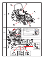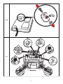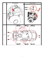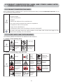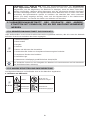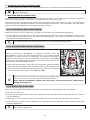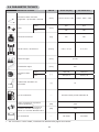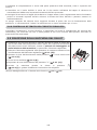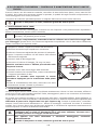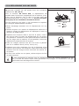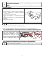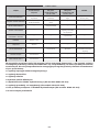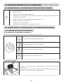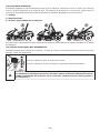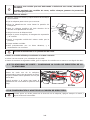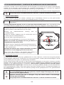
1
AC92-18 AC92-20 AC92-23 4x4 GB User‘s manual PL Instrukcja obsługi D Bedienungsanleitung ES Manual de usuario IT Manuale di istruzioni NL Gebruikershandleiding F Manuel d’utilisation 7 6 1.2 1 5 2 4 3 1 2 3 4 5 TYPE N°: AJ-102 ENGINE: B&S 23 HP VANGUARD (16.9KW) YEAR OF PRODUCTION: xxxx WEIGHT: 299kg FABRICATION: Seco GROUP a.s., BRANCH PLANT 02 Jicin , Jungmannova 11 Czech Republic 6 CE CONFORMITY: 2006/42/EC;2004/108/EC 2000/14/EC;2002/88/EC 8 1.3.1 9 MADE IN EUROPE 7 100 1.3.2a 2 dB 1.3.2b MAX 18 o 1.3.2c 1.3.2d 3 1 3.1 2 3 5 4 3.3a 4 3.3b 1 2 3.3c 5 3.3d 1 8 2 7 4.1 6 3 4 5 6 AC 92-18(20) AC 92-23 4x4 MAX MIN 6.3.13 50 50 50 50 6.4 50 10 50 50 7 50 FOREWORD Dear customer, Thank you for purchasing this riding mower from Seco GROUP a.s., a company renowned both in Europe and internationally as a manufacturer of quality machines and accessories for the maintenance of grass areas. This user’s manual includes instructions about the safe assembly, operation and maintenance of your machine. Study this user‘s manual carefully. Follow the instructions contained in this user‘s manual precisely so that operating the machine is easier and that it is used optimally and has a long lifetime. Do not use the machine until you have thoroughly read all instructions, restrictions and recommendations contained in this user’s manual. Keep the user‘s manual for future use. This user‘s manual needs to be considered a part of the riding mower that must be included with the tractor in the event that it is sold. If anything is unclear or you have questions, do not hesitate to contact one of our more that 100 authorised, professionally-equipped service centres located all over Europe, where trained and tested experts will be ready to assist you. SYMBOLS USED IN THIS USER‘S MANUAL SYMBOL MEANING These symbols mean „ATTENTION” and “WARNING”, they inform you about things that may damage your machine and/or cause serious injury to the user. This symbol indicates an important instruction, property, procedure or issue, which you need to be aware of and adhere to during assembly, operation and maintenance of the machine. This symbol indicates useful information relating to the machine or to its accessories. The symbol is a reference to an image in the front part of the user‘s manual. It is always accompanied by the number of the image. This symbol is a reference to another chapter in this or another user‘s manual and most often it is shown together with the number of the chapter to which it refers. REFERENCES TO DIRECTIONS Left and right side L Front and rear side R R L = Left side, R = Right side F R = Rear side, F = Front side 8 1. TECHNICAL INFORMATION 1.1 USE The machine model AC92-18(20) or AC92-23 4x4 under the brand name CROSSJET is a dual-axle terrain riding mower designed for mowing maintained and unmaintained grass-covered level and sloped areas up to an incline of 18°(32%), that are free of foreign objects (stones, fallen branches, bones, hard items, etc.). It can be used to mow multi-year vegetation, intertwined with raspberries, blackberries and various other weeds. Any use of this riding mower, which is not described in this user’s manual and which goes beyond the use here described is considered to be in contradiction to its intended purpose or use. The manufacturer of the machine is not responsible for damages arising from such use; the risk is borne by its user. The user is also responsible for adhering to the conditions prescribed by the manufacturer for the operation, maintenance and repairs of this machine, which may only be used, maintained and repaired by persons that know these conditions and have been informed about possible dangers. Only accessories, which have been approved by the manufacturer may be connected to the machine. The use of other accessories will result in the warranty being immediately void. 1.2 MAIN PARTS OF THE RIDING MOWER Riding mower models AC 92-18, AC 92-20 or AC 92-23 4x4 consist of the following basic sections: (1) Hood with storage space The hood is a combination of plastic and metal covers, which contain the storage space for the battery. (2) Frame with a bumper The frame with the bumper serve as a bearing element for most of the main parts of the machine. (3) Front axle with wheels including steering* The front axle enables the wheels to turn. The wheels are turned by the steering wheel by means of a comb mechanism. The AC 92-23 4x4 machine is equipped with front-wheel drive. All-wheel drive is activated automatically, with power distributed to the individual axles depending on the current traction conditions and the travel mode (forward or reverse). (4) Mower deck 1.2 The mower deck mows the grass. It is located under the machine. It consists of a cover, main plate, blade holders and two massive mowing blades. The deck is powered by the machine’s engine through an electromagnetic clutch and a V-belt. (5) Engine, gear box including rear-wheel drive via a by-pass The four-stroke petrol engine is mounted to the frame in the rear part of the machine. The gear box with hydrostatic power transmission serves to change gears while driving. The by-pass lever is located on the machine’s rear plate. It serves to activate and disable the gear box for the rear wheels. (6) Folding frame of the machine The folding frame is intended to prevent the machine from rolling over by 180° if for any reason it loses stability and rolls on to its side. (7) Driver’s location The comfortable seat enables easy access to all control elements on the machine. The seat used ensures safe and comfortable operation. *ATTENTION: The AC92-23 4x4 machine does not enable for construction reasons the disconnection of the front axle drive – the hydraulic system is not equipped with a bypass valve, which significantly limits the option of moving the machine when the engine is not running. During such movement the front axle is significantly overloaded and may be damaged. The by-pass lever on this machine is primarily used to bleed the hydrostatic system. The machine must not be used (gear shifted into drive) if the by-pass lever is in the disengaged position - there is a danger of damage to the transmissions!! 9 1.3 PRODUCT IDENTIFICATION LABEL AND OTHER LABELS WITH SYMBOLS USED ON THE MACHINE 1.3.1 PRODUCT IDENTIFICATION LABEL Every riding mower is marked with a product identification label, located underneath the seat. It can be accessed by lifting the seat. 1. Machine model 2. Engine model 3. Year of production 4. Weight 1.3.1 5. Name and address of the manufacturer 6. EC codes used to assess the product’s compliance 7. Compliance mark of the product 8. Logo of the manufacturer 9. Guaranteed noise level according to directive 2000/14/EC The seller will write down the serial number on the other side of the front page of this manual when handing over the machine. 1.3.2 OTHER LABELS AND THEIR MEANINGS The following labels and stickers are attached to the machine: Labels on the mowing deck: 1.3.2a Danger Do not step on Rotating tools Guaranteed noise level 100 dB Labels on the fairing under the seat: 1.3.2b Danger Do not touch during operation Follow the manual when repairing Do not leave the machine when driving Caution, deflected objects Read the manual Do not mow near other people Do not take on passengers Do not drive perpendicular to the slope Keep unauthorised persons at a safe distance MAX 18 o Maximum working incline 10 Labels on the rear side of the machine: Careful Hot surface! 1.3.2c Danger of burns Labels at the travel direction lever: Choke Cruise control 0 Cruise control activated 1 Cruise control deactivated Fast 1.3.2d Slow F Travel forward N Neutral R Travel in reverse It is strictly forbidden to remove or damage labels and symbols attached to the accessory. In the event of damage or illegibility of the label, please contact the supplier or machine manufacturer and request a replacement. 11 1.4 TECHNICAL PARAMETERS BASIC PARAMETERS Dimensions of the machine (length x width x height) UNITS AC 92-18 (20) AC 92-23 4x4 [mm] 2310 x 1010 x 1510 2310 x 1050 x 1510 814 814 780 790 [kg] 317 350 [km/h] 0-8.5 / 0-4.5 0-9 / 0-5 Front Wheelbase [mm] Rear Weight of the machine Speed forward / reverse Mowing height [mm] 50-100 Mowing width [mm] 920 Front Wheel dimensions 16x6.5-8 16x6.5-8 20x10.0-8 20x10.0-8 ["] Rear Fuel tank capacity [l] 12 Fuel type --- Lead-free petrol Natural 95 Guaranteed emission level of acoustic power LWA [dB] <100 Declared emission level of acoustic pressure at the place of operation LpAd according to EN ISO 11201 [dB] <100 Type of battery --- * - for specific values see the table on the next page. 12 12V 24aH 12V 32aH Engine BS18 Revolutions ±100 (min-1) Declared emission level of acoustic pressure at the place of operation LpAd (dB) according to EN ISO 836+A1/A2, Annex H and EN ISO 11201 3000 88.4 Vibration acceleration aggregate value (m.s-2) according to EN 836+A1/A2, annex G seat steering wheel floor 0.23 2.38 1.61 total vibrations av according to EN 1032 vibrations transferred to the arm ahv according to EN 1033 BS20 3000 90 0.56 < 2.5 BS23 3000 91 1.5 < 2.5 13 2. WORK SAFETY AND HEALTH Riding mowers models Ac 92-18, AC 92-20 and AC 92-23 4x4 under the brand name CROSSJET are manufactured according to valid European safety norms. The machine’s manufacturer confirms this 10). fact in the Statement of compliance, which is included at the end of this user’s manual ( If this machine is used properly and according to the user’s manual, it is very safe. In the event that work safety is not adhered to and all warnings in this manual are not respected, this riding mower may cut off hands, legs or deflect objects and so may cause serious injury or death to persons, damage or destructions of the machine or one of its parts or accessories. 2.1 SAFETY INSTRUCTIONS The person primarily responsible for their own safety and the safety of others during the operation of the riding mower is its user. The manufacturer takes no responsibility for the injury of persons or damage to the machine and ecological damage resulting from the machine not being used and operated in accordance with all safety instructions included in this user’s manual. 2.1.1 GENERAL SAFETY INSTRUCTIONS ! This machine may only be driven by a person over 18 years of age that has read this user’s manual. ! The user of the machine is responsible for the safety of persons in the vicinity of the working area of the machine. ! It is not permitted to perform any technical modifications to the machine and its accessories without the manufacturer’s written consent. Unauthorised modifications may lead to hazardous work safety conditions and void the warranty. ! Adhere to all requirements relating to fire safety ( 2.4). ! Do not remove safety stickers or labels from the machine. ! Do not stay in the vicinity of the machine or under it, if it is lifted and is not sufficiently secured against falling or tipping over in the lifted position. ! Always turn off the mowing deck and engine and take the key out of the ignition, when: you are cleaning the machine you are removing accumulated grass from the mowing deck you have driven over a foreign object and it is necessary to check whether the machine has been damaged or it is necessary to remedy the damage the machine is vibrating with unusual force and it is necessary to identify the cause of the vibrations you are repairing the engine or other moving parts (also disconnect cables from the spark plugs) 2.1.2 BEFORE USING THE MACHINE ! Do not use the riding mower if it is damaged or if any of its protective elements are missing. All covers and other protective elements must always be in their place. Therefore, do not remove or put out of operation any of the machine’s protective elements. Regularly check that these elements are working correctly. ! Do not work with the machine after consuming alcohol, drugs or medication affecting your perception. ! Do not work with the machine if you suffer from dizziness, fainting or if you are weakened or distracted in any other way. ! Before putting the machine into operation thoroughly learn about all the control elements and ensure that you can control them in such a way that if necessary you can immediately stop or turn off the engine. ! Do not adjust the engine regulator or the engine speed limiter. ! Before you start working with the machine, remove from the surface of the area you will be mowing, all stones, pieces of wood, wire, bones, fallen branches and other items, which could be deflected during the mowing process. 14 ! Remove all defects before further use. Before starting work thoroughly check that the belts are tensioned, the blades are sharp and that the area inside the mowing deck is clear. 2.1.3 WHILE OPERATING THE MACHINE ! As this machine is intended for mowing grass on unmaintained areas where the operator may not always have full visibility and knowledge of the condition of the area being mowed (trenches or holes), the machine is equipped with a folding frame. ! The machine must not be used for work on slopes with an incline greater than 18° (32%), and when using the 4x4-drive on slopes with an incline greater than 20°(32%). ! Transport of other passengers, animals or loads directly on the machine is forbidden. Transport of loads is only permitted on trailers approved by the machine’s manufacturer. ! Even when leaving the machine for a short time, always remove the key from the ignition. ! If you are driving the machine away from the work area where you are mowing, always disengage the mowing deck and lift it to the transport position. ! Do not mow near piles of material, holes or banks. The riding mower may suddenly roll over if the wheel goes over the edge of a hole, trench or an edge that may collapse. ! When working, avoid concrete supports, tree stumps, garden bed and footpath kerbs, which must not come into contact with the blades and so cause damage to the mowing deck and the machine’s mechanism. ! In the event of an impact into a rigid object, stop and turn off the mowing deck and engine and inspect the entire machine, particularly the steering mechanism. If necessary perform repairs before starting up the engine again. ! Whenever possible avoid using the machine in wet grass. Reduced traction may lead to skidding. ! Avoid obstacles (e.g. sudden change in the incline of a slope, trenches, etc.) on which the machine could roll over. ! If mowing is disengaged, the mowing deck must always be in the transport position. ! Do not attempt to maintain the stability of the machine by stepping on the ground. ! Only use the machine in daylight hours or with good artificial lighting. ! Driving the machine on public roads is not permitted. ! When operating the machine do not wear loose clothing and short pants, use solid fully-closed footwear. Never operate the machine when wearing sandals or barefoot. ! Do not leave the engine running in closed areas. The exhaust fumes contain substances that are odourless but are fatally poisonous. ! Do not put your hands or legs underneath the mowing deck cover. Never put any part of your body near the rotating or moving parts of the machine. ! Do not start the engine without an exhaust. ! Usually the noise emitted during mowing does not exceed the acoustic pressure and acoustic power 1.4). In certain cases, however, it may under certain values specified in this user’s manual ( conditions and due to the condition of the terrain exceed the specified noise levels for a short time. ! The machine manufacturer recommends the use of hearing protection when operating the machine because stressing the hearing organ with an excessive noise level or long term effects of noise may lead to permanent hearing damage. ! Always pay full attention to driving and other activities performed with the machine. The most common causes of loss of control over the machine are for example: Loss of wheel traction. Excessive speed, not adjusting speed to current conditions and terrain properties. Sudden breaking where the wheels lock up. Using the machine for purposes for which is was not designed. 15 2.1.4 AFTER FINISHING WORK WITH THE MACHINE ! Always maintain the machine and its accessories clean and in good technical condition. ! The rotating blades are sharp and may cause injuries. Whenever handing the blades always use protective gloves or wrap the blades. ! Regularly check the nuts and bolts securing the blades so that they are tightened with the appropriate 6.3.6). amount of torque ( ! Pay special attention to lock nuts. After the nut is loosened a second time its locking capability is reduced and therefore it needs to be replaced with a new one. ! Regularly inspect all components and if necessary replace those that need to be replaced based on the manufacturer’s recommendations. 2.2 SAFETY INSTRUCTIONS FOR WORK ON SLOPES Slopes are the main cause of accidents, loss of control over the machine or subsequent roll-overs, which may lead to serious injuries or death. Mowing on slopes always requires an increased level of attention. If you are not sure, or it exceeds your ability, do not mow on slopes. ! Riding mowers can be used on slopes with a maximum incline up to 18° (32%) and when 4x4-drive is used on slopes with a maximum incline of 20°(32%) and only in the direction of the fall line, i.e. 5.5.4. upwards or downwards. More information ! When changing direction increased care is needed. Do not turn on a slope unless it is absolutely necessary. ! Watch out for holes, roots, uneven terrain. Uneven terrain may cause the machine to turn over. High grass may conceal hidden obstacles. Therefore, remove all foreign objects from the area where you wish to mow in advance. ! Select such a speed so that you do not need to stop when on a hill. ! Be very careful when attaching various hitch attachments. It may lead to a reduced stability of the machine. ! Perform all movements on a slope slowly and smoothly. Do not make sudden changes to speed or direction. ! Avoid starting up or stopping on a slope. In the event that the wheels lose traction, turn off the power to the blades and drive slowly down the hill. ! Start driving very carefully and slowly when on a slope so that the machine does not “skip”. Always reduce the machine’s driving speed before a slope, and especially when driving down a hill lower the driving speed to minimum to take advantage of the braking effect of the transmission. This braking effect is significantly higher on the AC 92-23 4x4 machine. 2.3 CHILD SAFETY If the riding mower operator is not prepared for the presence of children then a tragic accident may happen. The movement of a riding mower attracts the attention of children. Never assume that children will remain in the location where you last saw them. ! Do not allow children without supervision in areas where you are mowing grass. ! Always be prepared - if children approach you then turn off the machine. ! Before and while reversing look behind you and at the ground. ! Never transport children, they may fall and seriously injure themselves, or they may dangerously interfere with the riding mower controls. Never allow children to operate the machine. ! Pay increased attention in places with limited visibility (near trees, bushes, walls, etc.). 16 2.4. FIRE SAFETY When reversing the riding mower it is necessary to adhere to fundamentals and regulations for work safety and fire protection relating to work with this type of machine. ! Regularly remove flammable substances (dry grass, leaves, etc.) from the area around the exhaust, engine, battery and anywhere, where they could come into contact with petrol or oil and subsequently catch on fire and so result in a fire on the machine. ! Allow the riding mower engine to cool down before parking it in a closed location. ! Pay increased attention when working with petrol, oil and other flammable substances. These are very flammable substances, the fumes of which are explosive. Do not smoke during this work. Never unscrew the petrol tank cap and refill with petrol while the engine is running, if the engine is hot or if the machine is in a closed location. ! Check the petrol lines before using and do not fill the petrol all the way up to the bottleneck of the tank. The heat generated by the engine, sun and the expansion of the fuel may lead to the petrol overflowing and a subsequent fire. ! For storing flammable substances use containers designed for this purpose. Never store a canister with petrol or the machine inside a building near any source of heat. ! Pay increased attention when working with the battery. The gas inside the battery is highly explosive, therefore do not smoke in the vicinity of the battery and do not use an open flame so as to avoid serious injuries. 17 3. PREPARING FOR THE MACHINE FOR OPERATION 3.1 UNPACKING AND INSPECTING THE CONTENTS The riding mower is supplied wrapped and in crate packaging. For transportation reasons some machine assemblies are disassembled in the production plant and it is necessary to install them before putting the machine into operation. The unpacking and preparation for operation is performed by the seller within the scope of the pre-sale service. Inspect immediately after delivery that the packed machine has not been damaged. In the event of damage inform the carrier. If the complaint is not lodged in time, no potential demands can be claimed. Check that the machine model is the same as you ordered. In the event of an irregularity do not unpack the machine and immediately report this discrepancy to the supplier. 1. 2. 3. 4. 5. 3.1 Crate packaging Seat Folding frame Steering wheel Documentation (located underneath the hood) Using a suitable tool (e.g. crowbar or hammer, etc.) remove the crate (1) and the packaging on the machine. Visually inspect the machine and assemblies for damage that may have occurred during transport. Unpack all separatelz packed assemblies and inspect them. The basic package includes: Riding mower Seat (2) Folding frame in the folded state (3) Steering wheel (4) Documentation (5) (packed parts list, user’s manual for the riding mower, user’s manual for the engine, user’s manual for the battery, service log book) 3.2 DISPOSAL OF THE PACKAGING After unpacking the machine ensure that the packaging material is properly disposed of or recycled. The disposal must conform to relevant waste disposal laws valid in the user‘s country. Disposal may be performed by a specialised company. 3.3 ASSEMBLY OF THE SEPARATELY PACKED ASSEMBLIES Due to the technical nature of this task the machine is prepared for operation by the seller of your riding mower (according to the following instructions). Before starting installation, remove all covering, protective and fastening materials. a) Install the seat springs: Tilt out the seat. Unscrew the bolts holding down the seating spring under the bracket. Then install the springs so that they are above the bracket. Set the appropriate distance of the seat from the steering wheel by pressing the seat positioning lever which is a part of the seat. 18 3.3a Under no circumstances should you sit on the seat before installing the seat springs into a working state! A collision with the hood could occur and damage it. b) Install the steering wheel: Using a hammer and a suitable rod, knock out the pin (2), which is inserted in the shaft hole (1). The steering wheel is set it two height positions, which are set by two holes in the steering wheel shaft. Select the optimal steering wheel position, attach it on to the shaft (1) and turn it so that the holes in the steering wheel and the shaft align. 3.3b Reinsert the pin into the hole and knock it in using a hammer. c) Set the folding frame to the correct position: Using the quick coupler levers set the folding frame to the vertical position. 3.3c d) Connect the battery: Open the storage area in the hood and loosen the bolts on the battery pole terminals. Black wire Place on the (+) pole of the battery and secure in place with the bolt. Brown wire Place on the (-) pole of the battery and secure in place with the bolt. 3.3d Connecting the wires in opposite to that described above will damage the machine. When disconnecting the battery, always disconnect the negative (–) pole of the battery first. When putting the battery into operation and when performing maintenance on it, proceed according to the instructions in the user’s manual for the battery. Also follow all safety instructions contained therein. Now prepare the machine for the first start up according to the following chapter. 3.4 CHECKS PRIOR TO STARTING UP Due to the technical nature of this task the machine is put into operation by the seller of your riding mower (according to the manufacturer’s instructions). 3.4.1 CHECKING THE MOTOR OIL The tractor must be in a horizontal position before the oil level can be checked. The cap of the filling opening is located on the engine covers at the rear side of the machine. Screw out the oil dipstick, wipe it dry, reinsert it and screw in. Then again screw it out and take the oil level reading. Oil level dipstick: (1) - (ADD) low oil level (2) - (FULL) maximum oil level The oil level must be between the two marks on the dipstick. If it is not, fill up with motor oil so that it reaches the “FULL” mark. The motor oil type is indicated in the user’s manual of the engine. The oil level must be checked before every work session. 3.4.2 CHECKING THE BATTERY Check the battery charge level according to the user’s manual of the battery. 19 3.4.3 FILLING THE FUEL TANK WITH FUEL For safety reasons the riding mower is transported without fuel and before the first start up it is necessary to fill it up. The fuel tank is located at the rear of the machine and has a capacity of 12 l of fuel. Use only petrol with the octane number specified in the user‘s manual of the engine, i.e. lead-free petrol NATURAL 95. Defects caused by the use of incorrect fuel are not covered by the warranty! Only fill the fuel tank with the engine turned off and when the engine is cold. Fill up the fuel tank in a well ventilated location. When handling fuel, do not eat, smoke or use an open flame. For filling use a funnel designed for refilling fuel. Ensure that fuel is not spilled when refilling. Spilled fuel can very easily catch on fire. If fuel does spill, thoroughly wipe dry. Store fuels out of the reach of children. Procedure for filling up: Open the fuel tank cap. Open it slowly because there may be overpressure in the fuel tank caused by petrol vapours. Insert a funnel into the fuel tank opening and start to pour the fuel from the canister. After filling up the fuel tank always wipe dry the area around the fuel tank opening as well as the fuel tank opening itself. It is good to check the condition of the fuel lines. 3.4.4 CHECKING THE AIR PRESSURE IN THE TYRES Before putting the machine into operation, check the air pressure in the tyres. The air pressure in the front tyres must be 150 kPa. The air pressure in the rear tyres must be 80 kPa. 80 kPa 150 kPa The difference between the individual tyres may be ± 10 KPa. Do not exceed the maximum pressure marked on the tyres that are being used. 3.4.5 CHECKING THE OIL LEVEL IN THE HYDRAULIC CIRCUIT (APPLIES TO MODEL AC 92-23 4X4) The machine is supplied with a bled hydraulic circuit and with an equalisation tank with the prescribed amount of oil. The oil level in the tank may decline during transport. The equalisation tank is located in the rear part of the machine under the engine cover. Check that the oil level is between the two marks on the dipstick of the closing cap, if necessary fill up with the necessary amount of the prescribed oil. Wipe clean the area around the tank opening and the tank opening itself. Also regularly clean the entire tank, because any dirt in the oil reduces the lifespan of the oil filter and may possibly cause a malfunction. The system is fully bled during the first couple of hours of driving the machine – we recommend that you “run the machine in” with a mild load for 1 to 2 hours. 20 3.4.6 PERFORMING A LEAK TEST ON THE HYDRAULIC CIRCUIT Visually check the hydraulic circuit for oil leaks, namely the locations where fittings are connected to the transmissions. If you discover any leaks, inform your service centre. 3.5 DRIVING THE MACHINE FROM THE PALLET Prepare two suitable ramps and place them next to the pallet so that the machine’s wheels can ride on to them. If you drive off the pallet without ramps, there is a danger of damaging the underside of the machine, particularly the mowing deck! Lift the mowing deck into the transport position by pulling on the mowing 4.2.1 (10)). deck elevation lever ( Move the throttle lever from position ( 4.2.1 (5)). Pull out the choke lever ( approximately half way 4.2.1 (6)). Set the by-pass lever to position “1” ( 4.2.1 (11)). Start up the machine by turning the key to position slowly drive the machine down off the pallet. ( 4.2.1(1)) and Further details about starting up and stopping the engine are provided in 21 5.2 and 5.3. 4. OPERATING THE MACHINE 4.1 LOCATION OF THE MAIN CONTROL ELEMENTS 4.1 (1) Main power switch (2) Brake pedal (3) Parking brake lever (4) Travel direction lever, throttle lever, choke and cruise control disengage lever (5) Mowing deck elevation adjustment lever (6) Differential lock pedal (7) Motor hours counter (8) Mowing deck activation switch 4.2 DESCRIPTION AND FUNCTIONS OF THE CONTROL ELEMENTS 4.2.1 STANDARD CONTROL ELEMENTS (1) MAIN POWER SWITCH Serves to start up / shut off the engine. It has the following 4 positions: Ignition off / turn off the ignition Turn on / turn off the headlights on the hood Ignition on, the engine is running. Start engine – starting position (2) BRAKE PEDAL Pressing the brake pedal will slow down the riding mower. Never use the brake at the same time as the travel direction function – there is a danger of damaging the transmission! 22 (3) PARKING BRAKE LEVER 2 1 The parking brake has two positions. In position (1) the brake is not active, after shifting to position (2) while stepping down on brake pedal the parking brake is activated (will brake). Stepping on the brake pedal will deactivate the parking brake and the lever will automatically be released and shift to position (1). (4) TRAVEL DIRECTION LEVER It controls the power supplied to the rear wheels and regulates the speed of the machine in both directions. In the basic setting it is equipped with a mechanical cruise control function, which is automatically deactivated by pressing the brake pedal. F Forward travel Moving the lever closer to the letter F corresponds to a higher speed and vice versa N Neutral The machine is still R Reverse travel Moving the lever closer to the letter R corresponds to a higher speed and vice versa Changing the travel direction from forward to reverse or from reverse to forward is only possible after stopping the machine. When the brake pedal is stepped on the gear stick automatically shifts to position „N“. (5) THROTTLE LEVER Serves to regulate the engine speed. It has the following three positions: MAX Maximum engine speed MIN Minimum engine speed (idle) (6) CHOKE For starting a cold engine: CHOKE Starting a cold engine 23 (7) CRUISE CONTROL DISENGAGE LEVER This lever disengages the mechanical cruise control function and so it is possible to travel with the machine very accurately at a slow speed. Do not disengage the cruise control when travelling at a high speed! 0 Cruise control is engaged 1 Cruise control is disengaged (8) MOWING DECK RUN DOWN INDICATOR This indicator indicates when the mowing deck is on and running down. Light is on Flashing The mowing deck is activated The mowing deck is deactivated, but the blades are still rotating (the indicator flashes for approx. 10 seconds) (9) MOWING DECK ACTIVATION SWITCH Pulling out the activation switch upwards activates the mowing deck. Pushing it down deactivates the mowing deck. DEACTIVATED Deactivation of the mowing deck / the mowing deck is deactivated. ACTIVATED Activation of the mowing deck 24 (10) MOWING DECK ELEVATION ADJUSTMENT LEVER The lever serves to set the elevation height of the mowing deck from the ground. The lever has 4 work positions (50 - 60 - 75 – 100 mm), where the corresponding mowing height is 5 to 10 cm. The higher the number of the lever position, the higher vegetation height remains after mowing. There is also 1 transport position, which is 120 mm above the ground. When the lever is set to the transport position it is not possible to activate the mowing deck as a safety switch is built into this position. When travelling without mowing the lever must be set to the transport position! The mulching function can be improved by using a special accessory, a so-called „mulching set“, which is supplied separately as a special accessory for mowing maintained lawns. (11) BY-PASS LEVER – FREE MOVEMENT OF THE REAR WHEELS The by-pass lever serves to disengage the transmission for the rear wheel drive and is used to push or pull the machine without using the engine. The lever is located on the rear side of the machine and has the following two positions: Position Rear wheel drive (0) DISENGAGED (1) ENGAGED Use Lever is extended - for pushing the machine Lever is inserted - for driving the machine ATTENTION! On the AC 92-23 4x4 machine the lever is used primarily for bleeding the hydrostatic system. Due to the high demands on equipment, have this procedure performed by a specialised service centre. The machine must not be used (gear shifted into drive) if the by-pass lever is in the disengaged position - there is a danger of damage to the transmissions! 25 (12) MOTOR HOURS COUNTER The motor hours counter implicitly displays the total number of motor hours. By pressing the Mode button you gradually switch between the following maintenance functions: TMR 1 - individual trip counter. The value is reset by holding down the Mode button for 6 seconds. OIL CHG - oil change. The function has two oil change intervals. The first is after 5 hours (oil change after the engine has run itself in) and is shown only once. The second is after 25 hours (standard oil change). AIRFILTER SVC - cleaning or changing the air filter. The interval is set to 50 hours. Two hours before the set interval has elapsed the display will show a message lasting 10 seconds. After the interval has elapsed the display will show the message NOW. Any of the above mentioned alarms can be reset by holding down the Mode button for 6 seconds. Tampering with the counter will void the warranty – the motor hours connection is equipped with a tamper seal. Immediately contact your service centre if the motor hours counter malfunctions. (13) FOLDING FRAME The folding frame is intended to prevent the machine from rolling over by 180° if for any reason it loses stability and rolls on to its side. Under no circumstances does the protective frame serve as safety / protection feature for the operator! The folding frame has 3 positions: 1. Work 2. Maintenance 3. Auxiliary for handling the machine The individual positions are set using quick coupler levers on the sides of the frame. (14) DIFFERENTIAL LOCK PEDAL The pedal is used only if necessary and only when driving directly forward. It has two positions: ( ) When the pedal is pushed down the lock is engaged. ( ) When the pedal is released the lock is automatically disengaged. Use the lock only when driving directly forward and only if necessary (loss of traction). Never use the differential lock when changing travel direction. Otherwise there is a risk of serious damage to the transmission! 26 5. OPERATION AND HANDLING OF THE MACHINE Information which it is good to know before the riding mower is first turned on: The riding mower is equipped with safety contacts, which are connected by a switch located under the seat. The motor will automatically shut off when the driver leaves the seat and the machine is not secured using the parking brake. The engine can only be started when the mowing deck is turned off and the mowing deck elevation adjustment lever is in the transport position. 5.1 CHECKS PRIOR TO STARTING UP THE MACHINE Before starting up the riding mower check the following: 3.4.1) Oil level in the engine ( Battery charge level ( Fuel level ( 3.4.2) 3.4.3) Air pressure in the tyres ( 3.4.4) That the by-pass lever is in position “1” 5.2 STARTING UP THE ENGINE a) Set the mowing deck elevation adjustment lever to the transport position. b) Move the mowing deck activation switch to position “DEACTIVATED”. c) Move the travel direction lever to position “N”. d) Move the throttle lever to maximum engine speed. e) Pull out the choke. f) Start up the engine by moving the ignition key to position “Start engine”. After starting the engine, release the key. The key will automatically return to the position “Ignition on” As soon as the engine starts up, release the ignition key. The duration of starting up must not exceed 10 seconds, otherwise there is danger of damage to the switch! Never use fixed external starters to start the machine. This could damage the electrical wiring. It is possible to connect a higher capacity 12V battery. g) Push in the choke. h) Slowly move the throttle lever to the idle position (reduce the engine speed). Allow the engine to run several minutes before turning on the mowing deck. Never leave a started engine running in a closed or poorly ventilated area. Exhaust fumes contain gases that are harmful to your health. Keep your hands, legs and clothing away from moving parts and the exhaust. 5.3 TURNING OFF THE ENGINE a) Move the throttle lever to position “MIN”. b) If the mowing deck is activated, deactivate it by pushing down the switch. c) Turn off the engine by moving the key to position “STOP” and take the key out of the ignition. If the engine is overheated, allow it to run for a while at minimum speed. 27 Never stop the engine by merely getting off the seat, while leaving the key in the ignition in the position “ON” as this may result in an electrical defect. Always turn the key to the “OFF” position and remove it from the ignition. This will prevent an undesirable start up of the machine by an unauthorised person or children. Before turning off the ignition lower the engine speed to slow for the event of selfignition. Not following this instruction may result in damage to the engine and exhaust. Never disconnect the battery cables while the engine is running! This could damage the engine regulator. 5.4 ACTIVATING AND DEACTIVATING THE MOWING DECK 5.4.1 ACTIVATING THE MOWING DECK Move the throttle lever to position “MAX”. Using the mowing deck elevation adjustment lever set the position of the mowing deck and thereby the mowing height. Set the mowing deck activation switch to position “ACTIVATED”. Conditions for activating the mowing deck: - the driver is sitting in the seat of the machine - the mowing deck elevation adjustment lever is in the transport position 5.4.2 DEACTIVATING THE MOWING DECK Deactivate the mowing deck by pushing down the activation switch. If the driver leaves the seat, the engine will automatically shut down and thereby the rotation of the mowing blades also. However, never turn off the mowing deck by simply leaving the seat. If you do not move the key in the ignition from the position “ON” to position “STOP”, then a part of the electrical installation will still be live and this may result in it being damaged. Also the motor hours counter remains activated. 5.4.3 SETTING THE HEIGHT OF THE MOWING DECK FOR MOWING If you wish to set the mowing deck higher off the ground, move the mowing deck elevation adjustment lever upwards to position 50 or 100. This position is used to mow high and wet vegetation to a height of 5 or 10 cm. If you wish to set the mowing deck closer to the ground, move the mowing deck elevation adjustment lever downwards to position 50 or 60. This position is used to mow level and maintained areas to a height of 5 or 6 cm. 5.5 DRIVING THE MACHINE General warnings before driving: Make sure that the parking brake is disengaged. The parking brake must not remain in position “2” 4.2.1 (3)). Stepping down on the operating brake automatically disengages the parking brake. ( The by-pass lever must be set to position “1”, i.e. by-pass of the drive must be activated. When travelling to the mowing location, the mowing deck must be deactivated and raised in the transport position. 28 When travelling over obstacles higher than 8 cm (kerbs, etc.) it is necessary to use ramps to avoid damaging the mowing deck and the gear box. Avoid hard impacts of the front wheels against rigid obstacles, this may result in damage to the front axle, particularly when the machine is travelling at a high speed. 5.5.1 TRAVELLING FORWARD / REVERSING While accelerating slowly move the gear lever to the required direction of travel, i.e. to travel forward to position “F”, and to reverse to position “R”. If you wish to reduce your travelling speed, move the gear lever away from the direction of travel. To increase the travelling speed move the gear lever towards the direction of travel. Changing the direction of travel forward-reverse is possible only after moving the gear lever to position “N” and leaving the lever in this position for a short while. If the machine is not still, there is a danger of damaging the transmission. Never use the travel direction lever and the brake at the same time – this may damage the transmission. 5.5.2 STOPPING TRAVEL The movement of the machine forward / reverse is stopped by stepping down on the brake pedal and the gear stick will automatically return to the position “N”. The braking distance is shorter than 1.5m. In the event that cruise control is activated and the brake pedal is stepped on, it automatically moves to the neutral position. The braking distance is shorter than 2 m. The machine can only be stopped by gradually moving the travel direction lever to position “N” and then gradually stepping on the brake pedal. Never use the travel direction lever and the brake at the same time – this may damage the transmission. 5.5.3 TRAVELLING SPEED AND MOWING GRASS It generally applies that the wetter, higher and more dense the grass is, the lower the travelling speed that should be used. When the machine is travelling too fast or higher demands are place on it, the blade rotation speed declines as does the mowing quality. Under such conditions always set the engine to maximum power. If the grass is very high, it is necessary to mow it several times. First mow at maximum height and with narrower mowing coverage width if necessary. The second run can then proceed at the required mowing height. We recommend mowing in the parallel or cross direction. Covering the previous coverage of the machine increases the effectiveness of the blades and will improve the appearance of the mowed area. When travelling over uneven terrain the travelling speed may fluctuate. 29 5.5.4 TRAVELLING ON A SLOPE Riding mowers models AC 92-18 and AC 92-20 can work on slopes with an incline of up to 18° (32%). Right With the AC 92-23 4x4 machine it is possible in the longitudinal direction of the machine, i.e. in the direction up and down, however not along the contour, to travel over local uneven terrain up to a maximum incline of 20°. When working on a slope it is necessary to adhere to the following fundamentals: Pay increased attention when travelling on a slope. Always use a lower travelling speed and regulate the travelling speed by moving the travel direction lever. Only travel perpendicular to the contour, i.e. up and down. Travelling in the direction of the contour is possible with extra attention only when turning the machine. If at all possible, avoid travelling along the contour. AC 92-18 AC 92-20 AC 92-23 4x4 Max 18o (32%) Max 20 (32% ) o Wrong When turning ensure that a wheel does not drive over an elevated obstacle (rock, tree root, etc.) Travel slower when travelling down a slope or over obstacles. Pay special attention when turning and turning around on slopes. If you stop on a slope, always use the parking brake. When overloading the machine by travelling on slopes over 18° (20°) there is a risk of serious damage to the gear box. The manufacturer is not responsible for damage caused in this way. 30 6. MAINTENANCE AND ADJUSTMENT Properly performed regular maintenance and inspection of the riding mower helps to increase its problem-free operating lifetime. Worn or damaged parts must be replaced in time. When replacing parts use only original spare parts, using non-original parts may damage the machine, endanger the health of the driver or other persons and during the warranty period it voids the warranty. To order spare parts always contact the machine’s manufacturer or an authorised service centre. 6.1 OVERVIEW OF CHECKS AND MAINTENANCE INTERVAL Before every use After every 50 hours of operation or 1x per year Every 100 hours or 1x per year NOTE BATTERY --- Check the level of the electrolyte --- Check the connection FUEL FILTER --- --- Replacement --- BLADE HOLDER Check --- --- --- ELECTRICAL CIRCUIT Check safety switches Check cable bundles --- --- HYDRAULIC CIRCUIT Check for leaks --- --- --- ENGINE COOLING Remove grass from the engine grill and from the exhaust Cleaning --- --- DRIVE V-BELT Check for wear, tension --- --- --- MOWING V-BELT Check for wear, tension --- --- --- MOTOR OIL Check the level, fill up Oil change --- --- V-BELT TENSIONING MECHANISM Check if working Check condition --- --- OIL IN THE HYDRAULIC CIRCUIT --- --- --- Replacement after 200 hours of operation OIL FILTER --- --- Replacement OIL FILTER OF THE TRANSMISSION --- --- --- PARKING BRAKE Check if working Check mechanism --- TYRES Check pressure and condition --- --- Front 150kpa Rear 80kpa CONTROL ELEMENTS --- Check --- --- RUBBER COVERS Check condition --- --- --- FRONT DRIVE AXLE. (FOR MODEL AC 92-23 4x4) Check condition and fastening of all ball joints and check the steering connection rod --- --- The ball joints must have minimum looseness. The connecting rod must not show signs of damage (cracks) FRONT AXLE Check the condition of the joints and wheels Lubrication of vertical joints --- --- GEAR BOX Check for leaks Check condition of pulley Check oil level Oil SAE 10w-40 5w-50 (4x4) GEAR STICK Check if working Check belt tension --- --- STEERING --- Check if working --- --- SPARK PLUGS --- --- Clean and adjust or replace --- PART 31 Replacement after 200 hours of operation INTERVAL Before every use After every 50 hours of operation or 1x per year Every 100 hours or 1x per year NOTE FAN, ENGINE RADIATOR FINS --- --- Cleaning --- ALL PULLEYS Check condition and working order --- --- --- MOWING HEIGHT Check, lubrication of pins --- --- --- Cleaning Replacement Depending on nature of use - more often PART AIR FILTER MOWING BLADES Check condition and fastening --- --- --- MOWING DECK Check condition and fastening --- --- --- For the replacement of all parts or for repairs, which require disassembly and which are not described in this user’s manual, contact your seller or an authorised service centre. Contact your seller also for the following adjustments and maintenance: • adjustment of the electromagnetic clutch • adjustment of the brake • adjustment of the engine • replacement of V-Belts • bleeding of the hydraulic circuit (for model AC92-23 4x4) • adjustment of the front drive axle (for model AC92-23 4x4) • other problems with the hydraulic circuit (for model AC92-23 4x4) • in the event of other difficulties 6.2 DAILY CHECKS AND MAINTENANCE Before starting any maintenance or repair works, thoroughly reacquaint yourself with all instructions, restrictions and recommendations in this user‘s manual. Always remove the key from the ignition and disconnect the spark plug cables before performing any cleaning, maintenance or repairs. When working use suitable work clothing and work footwear. Use suitable gloves when handling a mowing blade or for activities where there is a risk of cuts. Avoid spilling fuel, oils or other harmful substances. Do not perform any major repairs if you do not have the necessary tools and a good knowledge about repairs of combustion engines! Dispose of used oil, fuel or other hazardous substances and materials in accordance environmental protection regulations in force. 32 6.2.1 BEFORE STARTING WORK CHECK TYRE PRESSURE Maintain the prescribed tyre pressure and check it regularly. Maintaining the prescribed tyre pressure is important for even mowing. Different pressure values may cause difficulty in driving, or even loss of control over the machine. Pressure in the front tyres: 150 kPa Pressure in the rear tyres: 80 kPa The difference between the individual tyres may be ± 10 kPa. CHECK THE OIL LEVEL IN THE ENGINE Park the riding mower on a horizontal surface. Open the hood and unscrew the cap of the filling opening. Screw out the oil dipstick, wipe it dry, reinsert it and screw in. Then again screw it out and take the oil level reading. The oil level must be between the two marks on the dipstick. If it is not, fill up with motor oil so that it reaches the “FULL” mark. Further details about checking and filling of oil are included in a separate user‘s manual supplied by the engine‘s manufacturer. CHECK CABLES AND BOLT CONNECTIONS Visually inspect the condition of cables and manually check the tightness of bolt connections. CHECK WORKING ORDER OF BRAKES Check that the brakes work properly. Proceed as follows: Park the machine on an even surface and turn off the engine. Step on the brake pedal and engage the parking brake. Using the by-pass lever disengage the rear wheel drive. Try to push the machine forward. If the rear wheels rotate, then the brakes need to be serviced. Contact an authorised service centre to have them adjusted. 6.2.2 AFTER FINISHING WORK SETTING UP THE MACHINE After finishing mowing elevate the mowing deck to the highest position and disable the drive for the mowing blades. Turn off the ignition, step on the brake pedal and secure the machine in position with the parking brake. CLEANING THE MACHINE Remove all dirt and grass remains from the surface of the tractor. Also remove grass, dust and other flammable materials from the edge of the exhaust. CLEANING THE MOWING DECK The mowing deck must be carefully cleaned after every use, namely the inside walls of the deck. Use a scraper, spatula or a current of water for cleaning. Proper maintenance and treatment of the mowing deck improves work quality and the machine’s lifespan. Proceed as follows: Secure the machine against movement. Elevate the mowing deck to the transport position. Lift (tilt out) the protective metal cover on the right side of the chamber. Clean out the entire area of the mowing deck. While cleaning also check the condition of the blades ( 33 6.3.6). WASHING THE MACHINE We do not recommend cleaning the machine using pressurised water! If despite this you do clean in this way, ensure that water does not enter the carburettor, air filter, ignition, exhaust, battery and other electrical components. Never direct the water current at the ball bearings (bearings in the blade holder, wheels) or on to parts in which there is oil (oil filter, filler neck, etc.) Before washing, park the machine on a suitable even surface. Plastic parts on the machine: - clean using a sponge and soapy water 6.3 REGULAR CHECKS, MAINTENANCE AND ADJUSTMENT 6.3.1 BATTERY Correct and regular maintenance of the battery will extend its lifespan. Therefore regularly check its condition according to the manual supplied by the battery’s manufacturer. Keep the battery contacts clean. If dirt accumulates on them, or they are rusty, clean them according to the recommendations of the battery’s manufacturer. Interruption of the circuit caused by the oxidation of the contacts may lead to the malfunction of the recharging function of the engine! Regularly check the condition of the electrolyte. The level must be in the range MIN - MAX. In the event of filling up the electrolyte, use only distilled water. A flat battery needs to be recharged as soon as possible, otherwise its cells may be irreparably damaged. It is always necessary to charge the battery before: - first use - when not planning on using it for a long time - before starting up after a longer break If it is necessary to replace the battery, always use a battery of the same size and type. Further details about checking and maintaining batteries are included in a separate user‘s manual supplied by the battery‘s manufacturer. 6.3.2 ENGINE CHANGING OIL Before changing the oil, prepare a container with a volume of at least 2 litres. So that all the oil flows out of the engine we recommend that you place something (e.g. wooden blocks) under the side opposite the drain screw. Drain the oil while it is still warm. Unscrew the filler opening of the oil so that the oil flows better and faster out of the engine. Unscrew the drain screw and allow the oil to fully flow out into the prepared container. Screw the drain screw back on and fill the engine with the correct User’s manual for the engine) amount of the recommended oil ( and close the oil filler cap. Use the dipstick to check the correct oil level. If necessary fill up the oil so that the oil is at the correct level. 34 Further details about replacing oil as well as its type and amount are included in a separate user‘s manual supplied by the engine‘s manufacturer. If you come into contact with used oil, we recommend that you thoroughly wash your hands with soap and water. Dispose of used oil according to environment protection laws. It is appropriate to deliver the oil in a closed container to a used oil collection point. Under no circumstances should dispose of the used oil with other waste or pour it down the drain, on to waste or on the floor. MAINTENANCE OF THE AIR FILTER Never allow the engine to run without an air filter. This rapidly wears out the engine. Maintain the air filter according to the instructions contained in the user‘s manual for the engine supplied by its manufacturer. MAINTENANCE OF THE SPARK PLUG For the engine to run perfectly the spark plug must be correctly set and clean from deposits. Always use only the spark plug specified by the engine’s manufacturer! If the engine was running shortly before the inspection or replacement, then the spark plug will be very hot. So be very careful not to burn yourself. Take off the spark plug cable and remove the spark plug using a wrench key. Visually inspect the exterior appearance of the spark plug. If the spark plug is visibility significantly worn out or if the insulator is cracked or it is peeling, it is necessary to replace it. If the spark plug is soiled or only slightly worn, it is necessary to carefully clean it with a suitable wire brush (copper). Using a gauge measure set the distance of the electrodes ( manual for the engine). User’s After performing maintenance on or replacing the spark plug, pull it tight in position. An incorrectly tightened spark plug heats up significantly and may cause serious damage to the engine. Check, maintain and replace spark plugs according to the instructions contained in the user‘s manual for the engine supplied by its manufacturer. REPLACEMENT OF THE FUEL FILTER Never allow the engine to run without a fuel filter. This rapidly wears out the engine. Replace the fuel filter according to the instructions contained in the user‘s manual for the engine supplied by its manufacturer. MAINTENANCE OF THE ENGINE COOLING Before each use or during work check that the grill on the engine is not clogged with grass remains or other objects. Clean the grill if necessary! After every 100 hours of operation or once a year remove the fan cover and clean soiled and clogged areas and the cooling fins of the engine. This will avoid the engine from overheating or being damaged. Clean more frequently if necessary. 6.3.3 REPLACING LIGHT BULBS Light bulbs are seated in a holder and are accessible after lifting the hood. Turn the rotating lock holding down the front hood, remove the light bulb by sliding it out of the holder, e.g. using a screwdriver and reinsert. Return the lid of the hood The light bulb type and its rating are specified in the spare parts catalogue. 35 6.3.4 REPLACING A FUSE If a fuse is damaged the engine will immediately shut off, the mowing deck will stop and all indicator lights on the dash board will turn off. In this case it is necessary to find the faulty fuse and replace it with a new one. Under no circumstances should you replace a faulty fuse with a fuse that has a higher current rating! Release the screw holding down the front hood, lift the hood and remove the protective fuse cover. Remove the old fuse and insert a new fuse with the same rating as the initial fuse, i.e. 15A or 5A. If even after replacing the fuse the engine or the mowing deck will not work, contact an authorised service centre. Under no circumstances should you attempt to remove the control unit of the electrical system! 6.3.5 LIFTING THE MACHINE If you wish to lift the riding mower, use a jack and supports. Proceed as follows: Place the jack underneath the gear box on the rear axle and lift the rear part of the machine. Insert two supports underneath the ends of the axles from the inner side of the rear wheels. Lift the front part of the machine and insert two supports under both ends of the front wheel axles. Never lean the machine to the side where the carburettor is located. Oil could enter the air filter! 6.3.6 MOWING DECK – CHECKING AND MAINTENANCE OF THE MOWING BLADES Before each use of the riding mower check the condition of the blades (damage, wear, condition of the cutting edge). If the blades are blunt, bent or broken it will negatively affect mowing quality. Damaged blades are very dangerous. A part of the material could break off and be deflected from the work area of the machine. Whenever handling the mowing blades, always use heavy-duty work gloves. REPLACING BLADES If due to frequent use the blades are worn or damaged, they cannot be balanced or sharpened properly, it is necessary to replace them immediately. The blades are sharpened from both sides so in the event that one side is blunt, it is possible to turn the blade around. 36 Always completely replace both blades and use new M16 lock nuts for attachment. This will ensure that the mowing deck is balanced and that the blades are securely attached. Proceed as follows: Turn off the engine and take the key out of the ignition. Secure the machine against movement. Elevate the mowing deck to the transport position. Open the metal cover on the right side of the mowing deck chamber. Screw out the M16 lock nut. 70 + 10 Nm Take off the fasting bolt, O-ring and blade. Install a new or sharpened blade proceeding in the reverse sequence. Use new, unused M16 lock nuts. Before replacing the second blade turn the blade holder with your hand by 180°. 275 + 25 Nm Replace the second blade following the same procedure as for the replacement of the first blade. When reinstalling the blades, ensure that they are correctly fastened and secured in place! SHARPENING THE BLADES The mowing blades must be sharp, statically balanced and straight. Blunt, incorrectly sharpened or damaged mowing blades cause grass to be torn out of the ground, damage to lawns and mediocre collection of mowed grass in the grass catcher. If the blades are merely blunt and do not exhibit any other damage, then they may be sharpened. After sharpening the pair of blades must be balanced. Balancing will prevent vibrations of the mowing deck. The weight difference between the individual blades may not exceed 2g. During replacement always also check the wear on the distance sleeves and mounting bolts, ensuring they are in perfect condition. If serious damage to the mowing deck is discovered it is necessary to have the machine thoroughly inspected at an authorised service centre. Always use a new, unused M16 lock nut. Never reuse a lock nut that has already been used, because safe attachment of the blade cannot be guaranteed! Do not repair a blade that is deformed or otherwise damaged, replace it immediately. Whenever handling the mowing blades, always use heavy-duty work gloves. Sharpening procedure: Turn off the engine and take the key out of the ignition. Secure the machine against movement. Elevate the mowing deck to the transport position. Open the metal cover on the right side of the mowing deck chamber. Screw out the M16 lock nut. Take off the fasting bolt, distance sleeve and blade. Remove the second blade in the same way as the first. Clean both blades. First sharpen with a grinder and then with a file. Do not sharpen directly on the mowing deck. 37 Install the sharpened blade proceeding in the reverse sequence. Use new, unused M16 lock nuts. Before replacing the second blade turn the blade holder with your hand by 180°. 6.3.7 MOWING DECK - CHECKING THE DRIVE PULLEY OF THE DECK Before every use of the machine, check the fastening bolt of the pulley. The bolt should be pulled tight with a torque of 80 Nm. The pulley is accessible after lowering the mowing deck to the lowest position. 80 Nm 6.3.8 CHECKING AND ADJUSTING THE DRIVE BELT When working on various parts of the machine‘s drive always turn off the engine and take the key out of the ignition. Regularly check the wear and tension of V-belts and the tensioning mechanism. A B The drive V-belts (travel and mowing) are automatically tensioned by a spring and a pulley. Before starting work or at least after every 50 hours of operation check the wear on the V-belts and the working order of the tensioning mechanism. Adjust the position of the drive belt tensioning pulley using adjusting nuts. Distance A = 60±2 mm. Distance B = 78 mm (set the mowing deck elevation adjustment lever to the second last position) When attaching a new belt pay special attention when working with the machine because the belt is not yet sufficiently run-in. 6.3.9 REPLACING BELTS Replacing drive belts is a relatively demanding operation, which needs to performed by an authorised service centre. 6.3.10 ADJUSTING THE TRAVEL DIRECTION LEVER If the travel direction lever returns to the “N” position on its own, it is necessary to adjust it. Have this task performed at a specialised service centre. 6.3.11 REPLACING WHEELS Before replacing one of the wheels, park the tractor on a horizontal and rigid surface, turn off the engine and remove the key from the ignition. Secure the machine against movement. Do not replace the wheel if the machine is not sufficiently secured in the elevated position! If you do not have suitable tools or the necessary knowledge, contact your seller. 38 Perform the replacement as follows: Place the jack underneath the front or rear bumper near to the wheel which you wish to replace. For model AC 92-23 4x4 – always place the jack against the frame - do not lean it on the transmission, this could damage it! Keep lifting the machine until the wheel, which you wish to change no longer touches the ground. Remove the protective cover from the wheel. Using a suitable screwdriver remove the retaining ring and remove the washer. Pull the wheel off the shaft. When reattaching the wheel proceed in the reverse sequence to its removal. Before attaching the wheel clean all parts and lightly grease the shaft with a plastic lubricant. Especially for wheels on the rear axle this lubrication is essential for the subsequent removal of the wheel. In the event that lubrication is not performed the subsequent attachment may be very difficult. When attaching the rear wheel pay attention to the mutual alignment of the pin on the shaft and the groove on the wheel. Finally check the tyre pressure. 6.3.12 REPAIRING A TYRE PUNCTURE The machine is equipped with tubeless tyres. In the event of a puncture have it repaired at a specialised tyre repair shop or at an authorised Seco machine service centre. 6.3.13 MAINTENANCE OF THE HYDROSTATIC TRANSMISSION For the reliable operation of the transmission it is necessary to maintain the correct oil level. In the event of problems with the transmission immediately seek the help of an authorised service centre, there is a risk of serious damage to the transmission. Machine model Oil type AC 92-18(20) SAE 10W-40, API CD AC 92-23 4x4 SAE 5W-50 synthetic oil 6.4 Oil level At least to half the height of the equalisation tank Between the marks on the dipstick in the tank cap (total oil volume in the hydraulic system is 6l) In the event of problems with the transmission immediately seek the help of an authorised service centre, there is a risk of serious damage. 39 6.3.14 OVERVIEW OF THE TIGHTENING TORQUE OF BOLT CONNECTIONS Steering: Torque 92 - 132 Nm M14 nut of steering segment M14 nuts of the angle pins on the steering 60 - 83 Nm Securing of pins on the front axle SC 2x4 40 - 50 Nm Engine: 60 - 70 Nm Bolt of the electromagnetic clutch Mowing: 33 - 48 Nm M10 nut of the tensioning mowing pulley M20 nut of the blade holder 250 - 300 Nm M16 nut securing the blades to the blade holder 150 - 200 Nm 60 - 80 Nm M12x30 bolt on the mowing pulley Driving controls: M10 nut on the drive pulley SC 2x4 24 - 30 Nm M10 nut on the drive pulley SC 4x4 35 - 45 Nm When lock nuts are removed and then returned they need to be replaced with new ones. 6.4 LUBRICATION Lubricate the machine according to the following lubrication diagram. Ball bearings of the tension pulleys, guide pulleys and bearings on the mowing deck are self-lubricating. Before putting the machine out of service for an extended period, thoroughly lubricate all places shown on the diagram. Namely the half axle of the front and rear axle (it is necessary to remove the rear wheels). Symbol Explanation Plastic lubricant 6.4 Oil SAE 30 Interval in hours Plastic lubricant is used to lubricate: steering segment - using a lubricating nipple wheel turning pin - using lubricating nipples mowing deck lifting arms - using a lubricating nipple tensioning pulley - remove, lubricate central front axle pivot pin - using a lubricating nipple (model AC 92-23 4x4 is equipped with selflubricating sliding sleeves) angle joints connecting the steering draw bars - remove, lubricate front wheel half-axles – on AC 92-23 4x4 mower, the interval is 10 hours! Pivot points are lubricated with oil: differential lock pedal brake pedal travel levers rear wheel half axles - the interval is 10 hours 40 7. REPAIRING MALFUNCTIONS AND DEFECTS Do not perform any repairs if you do not have the appropriate technical equipment and qualifications. The repairs described below may be performed by the user of the machine. Other repairs performed by the user that are not specified here will void the warranty. The manufacturer takes no responsibility for damages resulting from poorly performed unapproved repairs by the user. Malfunction, defect Remedy Remove grass that has accumulated on the underside of the mowing deck. The mowing deck mows unevenly Make sure that the blades are sharp, are not deformed or damaged. Check that the blades are properly fastened. Check the blade shafts and the seating of the bearings. Replace them if they are damaged or overly worn. When mowing, some vegetation remains uncut Check the bearing housings for damage. Based on your findings either repair or replace them. When mowing thick grass or grass that is too wet, an unmowed strip may remain. The travel speed should be adjusted to respect the mowing conditions by shifting into a suitable gear. The engine should not run with the throttle valve fully open. Check that the blades are sharp and undamaged. Replace the blades if necessary. Check the tension and condition of the V-belt of the mowing drive The mowing deck drive belt may be damaged, when it jumps out of the pulley while the machine is running. If it jumps out even after rechecking according to the following steps, it is necessary to replace the belt. 6.3.7). If necessary adjust the tension. Check the tension of the belt ( Check the belt guide pulleys. Check the set mowing height, adjust if necessary. The mowing deck drive belt stops during operation Check whether the movement of the belt is not prevented by a foreign object. If yes, remove the foreign object. Recheck all the belts. Buckled or cracked pulleys may cause problems. Replace if necessary. Check the inside surface of the pulley on the engine. If it is coarse or has cracks, it is necessary to replace the pulley. Check the parts of the tensioning mechanism for wear, replace the worn out parts if necessary. Change the travelling speed (e.g. slow down) Lift the mowing deck to a higher position If the grass is too tall or wet, the mowing deck drive belt may slip through. Check that the belt is not worn out. If it is, replace it. The mowing deck drive belt is slipping through Reduce the speed of the machine. Increase the mowing height. Check belt tension. If necessary adjust the tension. Check the tensioning mechanism (spring, pulley). Replace the spring if it is overstretched or damaged. Check the belt guide pulley. The mowing deck drive belt is being excessively worn out Check whether the movement of the belt is not prevented by a foreign object. If yes, remove the foreign object. Check the pulleys, if they are damaged, replace them. Check the set mowing height, adjust if necessary. Check the tension of the belt ( 6.3.7). If necessary adjust the tension. Check that the belt is not worn out or damaged. If it is, replace it. If it is loose, tension it. Check the tensioning mechanism spring. Replace the spring if it is cracked or damaged. The mowing deck cannot be started Check whether the movement of the belt is not prevented by a foreign object. If yes, remove the foreign object. Check the position of the mowing height lever. The safety switch prevents the activation of the electromagnetic clutch when in the transport position. Move the lever to the work position. Check the setting of the mowing deck switch 41 Malfunction, defect Remedy Check that the blades are not bent or twisted, also check that they are balanced. If they are deformed, replace them. Check that the belt does not have burned areas or irregularities, which could cause the vibrations. If the belt is damaged, replace it. Check that the blades are not worn out or damaged. Replace them if necessary. Belts vibrate extremely when turning on the mowing deck Check that the electromagnetic clutch switches properly. If the clutch is not working properly have it replaced or repaired at an authorised service centre. Check the inside surface of the pulley on the engine. If it is coarse or has cracks, it is necessary to replace the pulley. Check whether grass has accumulated on the underside of the mowing deck. It is necessary to remove this grass. Check whether the defect is not in the engine mount. Tighten bolts or replace as necessary. Check the tension of the belt ( 6.3.7. If necessary adjust the tension. Check the tension of the travel drive belt ( the tension spring, replace it if necessary. The travel drive belt of the machine is slipping 6.3.8). If necessary adjust its tension. Also check Check whether the belt is damaged or worn out. Check whether the movement of the clutch mechanism is blocked by a foreign object. If yes, remove the foreign object. Check the engine pulley or transmission pulley for damage. Replace if necessary. Check belt tension. The travel drive belt is being excessively worn out Check the tensioning mechanism, replace the damaged spring Check whether a foreign object is blocking the movement of the belt. If yes, remove the foreign object. Check the condition of the pulleys - replace the pulleys if necessary. The machine does not travel after shifting into gear Check the gear shifting mechanism - attachment of the draw bar of the travel direction lever. The machine is unusually loud after shifting into gear Check the oil level in the equalisation tank and fill it up if necessary. The machine loses power when travelling up a hill Check the oil level in the equalisation tank There are air pockets in the hydraulic circuit – drive the machine on level ground forward and back for several minutes. Contact your service centre. When the machine is under a high load and the ambient temperature is high, then the maximum working temperature of the oil may be exceeded. Lower the work demands on the machine. Check whether any pulleys are damage or deformed. Replace them if necessary. Extreme vibrations occur when travelling Check whether the belt has any burned spaces or other irregularities. Replace it if necessary. Check the tension of the travel drive belt ( 6.3.8). If necessary adjust its tension. Check that the mowing blades are balanced. Balance or replace them if necessary. The steering is slipping through or loose Check that the space between the pinion and the segment is not too large. If yes, adjust the cogged segment. Check for wear on the ball and socket joints. Replace the joints if necessary. Check that there is petrol in the petrol tank. Check that the prescribed procedure for starting the engine was followed ( 5.2) Check the fuse. Replace if necessary. The engine does not run Check whether the voltage on the battery terminals is 12 V. On a new machine check whether the battery was activated and charged. On new machines replace the spark plug and check that there is not oil accumulated on the cylinder due to incorrect handling. Check that all wire connections are in order and that the electrical system switches work. Check the engine again exactly according to the instructions in the User’s manual of the engine manufacturer. Have the electrical system checked at a specialised workshop. 42 Malfunction, defect Remedy Check that the prescribed procedure for starting the engine was followed ( the petrol in the petrol tank is clean. The engine is rotating but will not start up 5.2). Check that Check that the fuel filter is not clogged. Make sure that the throttle lever is in the position “CHOKE”. Check the engine again exactly according to the instructions in the User’s manual of the engine manufacturer. Have the cabling and switches checked at a specialised workshop. 7.1 ORDERING SPARE PARTS We recommend that you use exclusively original spare parts, which ensure safety and compatibility. Always order spare parts from an authorised distributor or service organisation, which is informed about the current technical changes performed on the products during manufacture. For easy, fast and exact identification of the necessary spare part always provide in your order the serial number found on the second side of the cover of this publication. Also provide the year of manufacture as shown on the product identification label under the seat. 7.2 WARRANTY Warranty conditions are provided on the warranty card, which is always provided together with the product by the seller. 43 8. POST-SEASONAL MAINTENANCE, MACHINE OUT OF OPERATION PUTTING THE After the end of the season or if you will not be using your riding mower for more than 30 days, make sure to prepare your machine for storage as soon as possible. If fuel remains in the petrol tank without movement for more than 30 days, a sticky deposit may form, which can have a negative effect on the carburettor and cause poor engine operation. For this reason empty the petrol tank. Never store the riding mower with a full petrol tank inside of buildings or poorly ventilated areas, where there are fuel vapours, open flames, sparking or lighting flames, furnaces, central heating, dry rags, etc. Handle fuels and lubricants with care, they are highly flammable and careless handling may lead to serious burns or damage to property. Only empty the petrol tank into approved containers outdoors away from open flames. Recommended procedure for preparing the riding mower for storage: Thoroughly clean the entire machine, especially inside the mowing deck ( 6.2.2). Never use petrol for cleaning. Use degreasing agents and warm water. Repair and paint dinted places to prevent corrosion from occurring. Replace faulty or worn out parts and tighten all loose nuts and bolts. Prepare the engine for storage according to the user’s manual for the operation and maintenance of the engine. Lubricate all lubrication locations according to the lubrication diagram ( Release the V-belt driving the mowing deck ( 6.4). 6.3.7) Take out the battery, clean it, fill it up with distilled water all the way to the bottom parts of the rings of the filling openings and charge fully. A battery that is not charged may freeze and crack. Store the battery in a cool, dry location, as necessary. Charge the battery every 30 days and regularly check its voltage. Store the riding mower covered in a clean and dry environment. The best way to ensure the riding mower‘s ideal operating condition for the next season is to have it inspected and tuned at an authorised service centre every year. 44 9. DISPOSAL OF THE MACHINE After the operational life of the machine is over, the owner of the machine is responsible for its disposal. This may be performed in two ways: a) Hand the machine over to a specialised company (scrap yard, secondary waste collection point, etc.). You will receive documented confirmation of the handover for disposal. b) Dispose of the machine yourself. In this case we recommend the following procedure: Dispose of the product utilising recyclable material according to the applicable waste disposal law. Disassemble the entire machine. Parts that can be reused should be cleaned, preserved and stored for further use. Separate the remaining parts into those that are and are not environmentally friendly, e.g. rubber parts (gaskets), lubricant remains in the bearings or on gears. The environmentally harmful components must be handled according to the relevant waste disposal law applicable in the country of the user, e.g. in the Czech Republic it is the Waste Act No. 185/2001 Coll. Sort the waste according to the Wastes Catalogue in accordance with the relevant ordinance. Handle environmentally friendly parts as a reusable resource. 45 10. ES STATEMENT OF COMPLIANCE pursuant to: Council Directive No. 2006/42/EC (Government directive NV 176/2008 Coll.) Council Directive No. 2004/108/EC (Government directive NV 616/2006 Coll.) Council Directive No. 2000/14/EC (Government directive NV 9/2002 Coll.) A. We: Seco Group a.s., Šaldova 408/30, Prague 8 branch: 02 Jičín, Jungmannova 11 Corporate number: 60193450 issue the following statement: B. Mechanical equipment - name: Riding mower - model: AC 92 - serial number: Description: AC 92 is a four-wheel self-propelled riding mower with a Briggs & Stratton 18HP, 20HP, 23HP engine. The power drive from the engine is transferred by a V-Belt to the travel drive transmission with a continuously variable gear and through an electromagnetic clutch to the mowing deck. The mowing deck is a singlerotor assembly with a vertical axis of rotation and a coverage width of 92 cm. It has two rotating blades on a single carrier. The mowed material is dispersed on the ground. C. Legislation forming the basis for assessment of compliance: EN 836+A1;2;3, EN ISO 3767-1;3, ISO 11684, EN ISO 11201, EN ISO 12100-2 Council Directive No. 97/68/EC (2002/88/EC) D. Assessment of compliance was performed according to the designated procedure in: - Council Directive No. 2006/42/EC, Article 5, (eqv. §5, para. 2 a), NV No. 176/2008 Coll.) - Council Directive No. 2004/108/EC, Article 7, (eqv. §4, para. 1, NV No. 616/2006 Coll.) - Council Directive No. 2000/14/EC, Annex VIII,(eqv.annex 7, NV No.9/2002 Coll.) under the supervision of a notified person from LRQA registration number 0088 Hiramford, Middlemarch Office Village, Siskin Drive Coventry CV3 4FJ, United Kingdom E. We confirm that: - this mechanical equipment defined above complies with the requirements in the above technical regulations and under normal operating conditions it is s a f e. - measures have been taken to ensure the compliance of all products introduced to the market with the technical documentation and the requirements contained in technical regulations. - guaranteed emission level of acoustic power is 100 dB(A). Measured mean values of acoustic power depending on the engine used: Engine BRIGGS & STRATTON 18 HP VANGUARD BRIGGS & STRATTON 20 HP VANGUARD BRIGGS & STRATTON 23 HP VANGUARD Speed (min-1) 3000±100 3000±100 3000±100 Measured value of ac.power [dB(A)] 97.47 97.34 97.58 Technical documentation in the extent as per attachment V is held by the manufacturer at: Seco GROUP odštěpný závod 02 AGS Jungmannova 11 506 48 Jičín In Jičín, on 1.10.2009 Ing. Jiří Pávek Member of the Board of Directors 46 Seco GROUP a.s. is dedicated to the continuous development and improvement of all its machines. Therefore, some technical differences in terminology may appear in this manual when compared with the actual product. No claims can be deduced from this. Print, duplication, publication and translation (even in part) must not be performed without the written consent of Seco GROUP a.s. The manufacturer reserves the right to change technical parameters of the product, without prior customer notification. 47 VORWORT Sehr geehrter Kunde, Vielen Dank für den Kauf dieses Aufsitzmähers von Seco GROUP a.s., ein sowohl in Europa als auch international renommiertes Unternehmen als Hersteller von hochwertigen Maschinen und Zubehör für die Pflege von Rasenflächen. Dieses Handbuch enthält Anweisungen über die sichere Montage, den Betrieb und die Wartung Ihrer Maschine. Lesen Sie diese Bedienungsanleitung sorgfältig durch. Befolgen Sie die in diesem Handbuch enthaltenen Anweisungen genau, so dass die Bedienung der Maschine einfacher ist und sie optimal genutzt wird und eine lange Lebensdauer hat. Verwenden Sie die Maschine erst, wenn Sie alle Anweisungen, Einschränkungen und Empfehlungen in diesem Handbuch gründlich gelesen haben. Bewahren Sie die Bedienungsanleitung für den späteren Gebrauch auf. Dieses Handbuch muss als Teil des Aufsitzmähers angesehen werden, das beim Verkauf des Mähers beigefügt werden muss. Wenn etwas unklar ist oder Sie Fragen haben, zögern Sie nicht, sich an eine unserer mehr als 100 autorisierten, professionell ausgestatteten Kundendienststellen in ganz Europa zu wenden, wo geschulte und geprüfte Experten bereit stehen, um Ihnen zu helfen. IN DIESEM HANDBUCH VERWENDETE SYMBOLE SYMBOL BEDEUTUNG Diese Symbole bedeuten „ACHTUNG“ und „WARNUNG“. Sie informieren Sie über Dinge, die Ihre Maschine beschädigen und/oder zu schweren Verletzungen für den Benutzer führen können. Dieses Symbol weist auf eine wichtige Anweisung, Eigenschaft, ein Verfahren oder Thema hin, dessen Sie sich bewusst sein müssen, und woran Sie sich bei Montage, Betrieb und Wartung der Maschine halten müssen. Dieses Symbol weist auf nützliche Informationen zur Maschine oder deren Zubehör hin. Das Symbol ist ein Verweis auf ein Bild im vorderen Teil der Bedienungsanleitung. Es wird immer durch die Nummer des Bildes begleitet. Dieses Symbol ist ein Verweis auf ein weiteres Kapitel in diesem oder einem anderen Benutzerhandbuch und wird meist zusammen mit der Nummer des Kapitels angezeigt, auf das es sich bezieht. HINWEISE AUF RICHTUNGEN Linke und rechte Seite L Vorder- und Rückseite R R L = linke Seite, R = rechte Seite V R = Rückseite, V = Vorderseite 48 1. TECHNISCHE INFORMATIONEN 1.1 VERWENDUNG Das Maschinenmodell AC92-18 (20) oder AC92-23 4x4 mit dem Markennamen CrossJet ist ein zweiachsiger Gelände-Aufsitzmäher zum Mähen gepflegter und ungepflegter grasbewachsener und geneigter Flächen bis zu einer Neigung von 18° (32 %), die frei von Fremdkörpern sind (Steine, abgebrochene Äste, Knochen, harte Gegenstände, usw.). Die Maschine kann eingesetzt werden, um mit Himbeeren, Brombeeren und verschiedenen anderen Ranken verflochtene mehrjährige Pflanzen zu mähen. Jegliche Nutzung dieses Aufsitzmähers, die nicht in diesem Handbuch beschrieben ist und die über die hier beschriebene Verwendung hinausgeht, wird als nicht vorgesehener Zweck oder Gebrauch betrachtet. Der Hersteller der Maschine ist nicht verantwortlich für Schäden, die aus einer solchen Nutzung entstehen; der Nutzer trägt das volle Risiko. Der Nutzer ist auch für die Einhaltung der Bedingungen verantwortlich, die der Hersteller für Betrieb, Wartung und Reparatur der Maschine vorschreibt. Diese darf nur von Personen verwendet, gewartet und repariert werden, die diese Bedingungen kennen und die über mögliche Gefahren informiert sind. Nur vom Hersteller genehmigtes Zubehör darf an der Maschine angebracht werden. Durch die Verwendung von anderem Zubehör erlischt die Garantie sofort. 1.2 HAUPTELEMENTE DES AUFSITZ-MÄHERS Die Aufsitzmäher AC 92-18, AC 92-20 oder AC 92-23 4x4 bestehen aus den folgenden Basissektionen: (1) Haube mit Stauraum Die Haube ist eine Kombination aus Kunststoff- und Metallabdeckungen, die den Stauraum für die Batterie enthalten. (2) Chassis mit Stoßstange Das Chassis mit der Stoßstange dient als tragendes Element für die meisten Hauptteile der Maschine. (3) Vorderachse mit Rädern einschließlich Lenkung* Die Lenkung erfolgt über die Räder der Vorderachse. Die Räder werden vom Lenkrad mittels eines Kammmechanismus gedreht. Der AC 92-23 4x4 ist mit einem Frontantrieb ausgestattet. Der Allradantrieb wird automatisch aktiviert. Dabei verteilt sich die Kraft auf die einzelnen Achsen, je nach aktuellen Traktionsbedingungen und Fahrmodus (vorwärts oder rückwärts). (4) Mähwerk 1.2 Das Mähwerk mäht das Gras. Es befindet sich unter der Maschine. Es besteht aus Abdeckung, Hauptplatte, Messerhaltern und zwei massiven Mähmessern. Das Mähwerk wird vom Motor der Maschine über eine elektromagnetische Kupplung und einen Keilriemen angetrieben. (5) Motor, Getriebe, einschließlich Heckantrieb über einen Bypass Der Viertakt-Benzinmotor ist im hinteren Teil der Maschine am Chassis montiert. Das Getriebe mit hydrostatischer Kraftübertragung dient zum Schalten der Gänge während der Fahrt. Der Bypass-Hebel befindet sich an der Rückwand der Maschine. Er dient zur Aktivierung und Deaktivierung des Getriebes für die Hinterräder. (6) Faltrahmen der Maschine Der Faltrahmen soll verhindern, dass die Maschine um 180° umkippt, wenn sie aus irgendeinem Grund die Stabilität verliert und zur Seite kippt. (7) Fahrerposition Der bequeme Sitz ermöglicht einen einfachen Zugriff auf alle Bedienelemente der Maschine. Der verwendete Sitz sorgt für eine sichere und komfortable Bedienung. 49 *ACHTUNG: Beim AC92-23 4x4 kann aus Konstruktionsgründen der Frontantrieb nicht abgeschaltet werden - das Hydrauliksystem ist nicht mit einem Bypass-Ventil ausgestattet, was die Möglichkeit, die Maschine zu bewegen, wenn der Motor nicht läuft, deutlich einschränkt. Während dieser Bewegung wird die Vorderachse deutlich überlastet und kann beschädigt werden. Der Bypass-Hebel dieser Maschine wird in erster Linie dazu verwendet, das hydrostatische System zu entlüften. Die Maschine darf nicht verwendet werden (ein Gang eingelegt werden), wenn sich der Bypass-Hebel in der deaktivierten Stellung befindet - es besteht die Gefahr von Schäden am Getriebe!! 1.3 KENNZEICHNUNGSETIKETT DES PRODUKTS UND ANDERE ETIKETTEN MIT SYMBOLEN, DIE AN DER MASCHINE VERWENDET WERDEN 1.3.1 KENNZEICHNUNGSETIKETT DES PRODUKTS Jeder Aufsitzmäher ist mit einem Produkt-Kennzeichnungsetikett markiert, das sich unter der Sitzbank befindet. Es ist durch Anheben des Sitzes zugänglich. 1. Maschinenmodell 2. Motormodell 3. Baujahr 4. Gewicht 1.3.1 5. Name und Adresse des Herstellers 6. Verwendete EG-Codes zur Compliance-Bewertung des Produkts 7. Compliance-Zeichen des Produkts 8. Hersteller-Logo 9. Garantierter Schallpegel gemäß Richtlinie 2000/14/EG Der Verkäufer notiert bei der Übergabe der Maschine die Seriennummer auf der Rückseite des Deckblatts dieser Anleitung. 1.3.2 ANDERE ETIKETTEN UND IHRE BEDEUTUNG Die folgenden Etiketten und Aufkleber sind an der Maschine angebracht: Etiketten am Mähwerk: 1.3.2a Gefahr Nicht auf die Maschine steigen Rotierende Werkzeuge Garantierter Schallleistungspegel 100 dB 50 Etiketten an der Verkleidung unter dem Sitz: 1.3.2b Gefahr Nicht während des Betriebs berühren Bei der Reparatur Anleitung befolgen Maschine nicht während des Fahrens verlassen Achtung, umherfliegende Objekte Lesen Sie das Handbuch Nicht in der Nähe anderer Menschen mähen Keine Passagiere mitnehmen Nicht senkrecht zum Hang fahren Unbefugte Personen in sicherem Abstand halten MAX 18 o Maximale Arbeitssteigung Etiketten auf der Rückseite der Maschine: Vorsicht Heiße Oberfläche! 1.3.2c Gefahr von Verbrennungen Etiketten auf dem Fahrtrichtungshebel: Choke Temporegler 0 Temporegler aktiviert 1 Temporegler deaktiviert Schnell 1.3.2d Langsam F Vorwärts N Neutral R Rückwärts Es ist strengstens verboten, am Zubehör angebrachte Etiketten und Symbole zu entfernen oder beschädigen. Bei Beschädigung oder Unlesbarkeit des Etiketts kontaktieren Sie bitte den Lieferanten oder Maschinenhersteller und fordern Ersatz an. 51 1.4 TECHNISCHE PARAMETER BASISPARAMETER Abmessungen der Maschine (Länge x Breite x Höhe) EINHEITEN AC 92-18 (20) AC 92-23 4x4 [mm] 2310 x 1010 x 1510 2310 x 1050 x 1510 814 814 780 790 [kg] 317 350 [km/h] 0-8,5 / 0-4,5 0-9 / 0-5 Vorne Radstand [mm] Hinten Gewicht der Maschine Geschwindigkeit vorwärts / rückwärts Schnitthöhe [mm] 50-100 Schnittbreite [mm] 920 Vorne Radabmessungen 16x6,5-8 16x6,5-8 20x10,0-8 20x10,0-8 ["] Hinten Fassungsvermögen des Kraftstofftanks [l] 12 Kraftstofftyp --- Bleifreies Benzin 95 Garantierter Schallleistungspegel LWA [dB] <100 Angegebener EmissionsSchalldruckpegel am Betriebsort LpAd gemäß EN ISO 11201 [dB] <100 Batterietyp --- * - Genaue Werte finden Sie in der Tabelle auf der nächsten Seite. 52 12V 24aH 12V 32aH Motor BS18 Drehzahl ±100 (min-1) Angegebener Emissionsschalldruckpegel am Ort des Betriebs LpAd (dB) nach EN ISO 836+A1/A2, Anlage H und EN ISO 11201 3000 88,4 Schwingbeschleunigung Gesamtwert (m.s-2) gemäß EN 836+A1/A2, Anlage G Sitz Lenkrad Boden 0,23 2,38 1,61 Gesamtschwingungen av gemäß EN 1032 Auf den Arm übertragene Schwingungen ahv gemäß EN 1033 BS20 3000 90 0,56 < 2,5 BS23 3000 91 1,5 < 2,5 53 2. ARBEITSSICHERHEIT UND GESUNDHEIT Die Aufsitzmäher-Modelle Ac 92-18, AC 92-20 und AC 92-23 4x4 unter dem Markennamen CrossJet sind nach den gültigen europäischen Sicherheitsnormen gefertigt. Der Hersteller der Maschine bestätigt 10). diese Tatsache in der Compliance-Erklärung am Ende dieser Bedienungsanleitung ( Wenn diese Maschine richtig und gemäß der Bedienungsanleitung verwendet wird, ist sie sehr sicher. Wenn die Arbeitssicherheit nicht eingehalten und nicht alle Warnungen in diesem Handbuch beachtet werden, kann dieser Aufsitzmäher Hände oder Beine abtrennen oder Gegenstände ablenken und dadurch schwere Verletzungen oder den Tod von Personen, Beschädigung oder Zerstörung der Maschine oder eines ihrer Teile oder des Zubehörs verursachen. 2.1 SICHERHEITSANWEISUNGEN Die Person, die in erster Linie für ihre eigene Sicherheit und die Sicherheit anderer beim Betrieb des Aufsitzmähers verantwortlich ist, ist dessen Benutzer. Der Hersteller übernimmt keine Verantwortung für die Verletzung von Personen oder für Schäden an der Maschine und Umweltschäden, die daraus resultieren, dass die Maschine nicht gemäß allen Sicherheitsanweisungen in diesem Handbuch betrieben wird. 2.1.1 ALLGEMEINE SICHERHEITSHINWEISE ! Diese Maschine darf nur von einer Person über 18 Jahren, die dieses Handbuch gelesen hat, gefahren werden. ! Der Benutzer der Maschine ist für die Sicherheit von Personen in der Nähe des Arbeitsbereiches der Maschine verantwortlich. ! Es ist nicht gestattet, ohne schriftliche Zustimmung des Herstellers technische Modifikationen an der Maschine und deren Zubehör vorzunehmen. Unerlaubte Modifikationen können zu gefährlichen Arbeitsbedingungen führen und die Garantie erlöschen lassen. 2.4). ! Beachten Sie alle Auflagen zur Brandsicherheit ( ! Entfernen Sie keine Sicherheitsaufkleber oder Etiketten von der Maschine. ! Bleiben Sie nicht in der Nähe der Maschine oder unter ihr, wenn sie angehoben ist und nicht ausreichend gegen Herabfallen oder Umkippen in der angehobenen Position gesichert ist. ! Schalten Sie immer das Mähwerk und den Motor aus und ziehen Sie den Schlüssel aus dem Zündschloss, wenn: Sie die Maschine reinigen Sie angesammeltes Gras aus dem Mähwerk entfernen Sie über einen Fremdkörper gefahren sind und es notwendig ist zu überprüfen, ob die Maschine beschädigt wurde, oder ob es notwendig ist, den Schaden zu beheben die Maschine ungewöhnlich stark vibriert und es notwendig ist, die Ursache der Vibrationen herauszufinden Sie den Motor oder andere bewegliche Teile reparieren (ziehen Sie auch die Kabel von den Zündkerzen ab) 2.1.2 BEVOR DIE MASCHINE BENUTZT WIRD ! Verwenden Sie den Aufsitzmäher nicht, wenn er beschädigt ist oder eine seiner Schutzvorrichtungen fehlt. Alle Abdeckungen und andere Schutzelemente müssen immer angebracht sein. Entfernen oder setzen Sie keine Schutzelemente der Maschine außer Betrieb. Die richtige Funktion dieser Elemente ist regelmäßig zu kontrollieren. ! Nach dem Konsum von Alkohol, Drogen oder Medikamenten, die Ihre Wahrnehmung beeinträchtigen, dürfen Sie nicht mit der Maschine arbeiten. ! Nicht mit der Maschine arbeiten, wenn Sie an Schwindel- oder Ohnmachtsanfällen leiden oder wenn Sie auf sonstige Weise geschwächt oder abgelenkt sind. ! Bevor Sie die Maschine in Betrieb nehmen, informieren Sie sich gründlich über alle Bedienelemente und sorgen dafür, dass sie diese so bedienen können, dass Sie, wenn nötig, den Motor sofort anhalten oder ausschalten können. 54 ! Verstellen Sie nicht den Motorregler oder den Drehzahlbegrenzer des Motors. ! Bevor Sie mit der Maschine zu arbeiten beginnen, entfernen Sie alle Steine, Holzstücke, Drähte, Knochen, heruntergefallenen Äste und anderen Gegenstände, die während des Mähvorgangs abgelenkt werden könnten, von der zu mähenden Fläche. ! Beheben Sie vor der weiteren Verwendung alle Mängel. Überprüfen Sie vor Arbeitsbeginn, dass die Riemen gespannt sind, die Messer scharf sind und dass der Bereich innerhalb des Mähwerks frei ist. 2.1.3 WÄHREND DER BENUTZUNG DER MASCHINE ! Da diese Maschine zum Mähen von Gras auf ungepflegten Flächen gedacht ist, bei denen der Bediener die zu mähende Fläche nicht immer voll einsehen kann und ihren Zustand nicht immer kennt (Gräben oder Löcher), ist die Maschine mit einem Faltrahmen ausgestattet. ! Die Maschine darf nicht für die Arbeit an Hängen mit einer Neigung von mehr als 18° (32 %), und bei Verwendung des 4x4-Antriebs an Hängen mit einer Neigung von mehr als 20° (32%), verwendet werden. ! Der Transport von Personen, Tieren oder Lasten direkt auf der Maschine ist verboten. Der Transport von Lasten ist nur auf Anhängern erlaubt, die vom Maschinenhersteller zugelassen sind. ! Auch beim Verlassen der Maschine für kurze Zeit immer den Schlüssel aus dem Zündschloss ziehen. ! Wenn Sie die Maschine aus dem Arbeitsbereich fahren, wo Sie mähen, deaktivieren Sie immer das Mähwerk und heben es in die Transportstellung. ! Nicht in der Nähe von Materialstapeln, Löchern oder Böschungen mähen. Der Aufsitzmäher kann sich plötzlich überschlagen, wenn ein Rad über den Rand eines Loches oder eines Grabens oder über eine Kante fährt, die zusammenbricht. ! Bei der Arbeit Betonstützen, Baumstümpfe, Gartenbeet- und Fußwegrandsteine vermeiden, die nicht mit den Messern in Kontakt kommen dürfen, da sie sonst Schäden am Mähwerk und dem Maschinenmechanismus verursachen können. ! Beim Aufprall auf einen festen Gegenstand Mähwerk und Motor anhalten und ausschalten und die gesamte Maschine, vor allem die Lenkung, überprüfen. Notwendige Reparaturen vor der Wiederinbetriebnahme des Motor durchführen. ! Wenn möglich, die Maschine nicht auf nassem Gras einsetzen. Reduzierte Traktion kann zu Rutschgefahr führen. ! Vermeiden Sie Hindernisse (z. B. plötzliche Änderungen der Neigung eines Hangs, Gräben, usw.), wo die Maschine umkippen könnte. ! Wenn das Mähen deaktiviert ist, muss sich das Mähwerk immer in der Transportstellung befinden. ! Versuchen Sie nicht, die Stabilität der Maschine zu erhalten, indem Sie auf den Boden treten. ! Die Maschine nur bei Tageslicht oder bei guter künstlicher Beleuchtung benutzen. ! Das Fahren der Maschine auf öffentlichen Straßen ist nicht erlaubt. ! Beim Betrieb der Maschine keine weite Kleidung und kurze Hosen tragen. Feste vollständig geschlossene Schuhe tragen. Nie die Maschine mit Sandalen oder barfuß bedienen. ! Den Motor nicht in geschlossenen Bereichen laufen lassen. Die Abgase enthalten Stoffe, die geruchlos aber tödlich giftig sind. ! Halten Sie Ihre Hände oder Beine nicht unter die Abdeckung des Mähwerks. Halten Sie nie ein Körperteil in die Nähe der rotierenden oder beweglichen Teile der Maschine. ! Den Motor nicht ohne Auspuff starten. ! Normalerweise übersteigen die beim Mähen abgegebenen Geräusche nicht die in dieser 1.4). In bestimmten Bedienungsanleitung angegebenen Schalldruck- und Schallleistungswerte ( Fällen können jedoch unter bestimmten Bedingungen und aufgrund der Beschaffenheit des Geländes die angegebenen Geräuschpegel kurzzeitig überschritten werden. ! Der Hersteller der Maschine empfiehlt bei der Bedienung der Maschine die Verwendung von Gehörschutz, da die Belastung des Hörorgans durch einen übermäßigen Geräuschpegel oder durch Langzeiteffekte zu dauerhaften Hörschäden führen kann. 55 ! Konzentrieren Sie sich immer voll auf das Fahren und andere mit der Maschine durchgeführte Aktivitäten. Die häufigsten Ursachen für den Verlust der Kontrolle über die Maschine sind zum Beispiel: Der Verlust der Radtraktion. Überhöhte Geschwindigkeit, Geländeeigenschaften. Nichtanpassen der Geschwindigkeit an aktuelle Gegebenheiten und Plötzliches Bremsen, bei dem die Räder blockieren. Einsatz der Maschine für Zwecke, für die sie nicht konstruiert wurde. 2.1.4 NACH DER ARBEIT MIT DER MASCHINE ! Halten Sie die Maschine und das Zubehör immer sauber und in gutem technischen Zustand. ! Die rotierenden Messer sind scharf und können Verletzungen verursachen. Beim Umgang mit den Messern immer Schutzhandschuhe tragen oder die Messer umwickeln. ! Überprüfen Sie regelmäßig die Muttern und Schrauben, die die Messer sichern, darauf, dass sie mit 6.3.6). dem entsprechenden Drehmoment angezogen sind ( ! Achten Sie besonders auf Sicherungsmuttern. Wenn die Mutter zum zweiten Mal gelöst wurde, ist ihre Sicherungsfähigkeit reduziert und sie muss durch eine neue ersetzt werden. ! Kontrollieren Sie regelmäßig alle Komponenten und wenn nötig ersetzen Sie diejenigen, die gemäß den Empfehlungen des Herstellers ersetzt werden müssen. 2.2 SICHERHEITSVORSCHRIFTEN FÜR DIE ARBEIT AN HÄNGEN Hänge sind die Hauptursache für Unfälle, Kontrollverlust über die Maschine oder nachfolgendes Umkippen, was jeweils zu schweren Verletzungen oder zum Tod führen kann. Das Mähen an Hängen erfordert immer ein erhöhtes Maß an Aufmerksamkeit. Wenn Sie nicht sicher sind oder es Ihre Fähigkeiten übersteigt, mähen Sie nicht an Hängen. ! Aufsitzmäher können an Hängen mit einer maximalen Steigung von bis zu 18° (32%) und beim Einsatz des 4x4-Antriebs an Hängen mit einer maximalen Neigung von 20° (32%) und nur in Richtung 5.5.4. der Falllinie, also nach oben oder unten, eingesetzt werden. Weitere Informationen ! Bei der Richtungsänderung ist erhöhte Vorsicht geboten. Nicht an einem Hang drehen, wenn es nicht absolut notwendig ist. ! Achten Sie auf Löcher, Wurzeln, unebenes Gelände. Unebenes Gelände kann dazu führen, dass die Maschine umkippt. Hohes Gras kann verborgene Hindernisse enthalten. Entfernen Sie daher im Voraus alle Fremdkörper von der zu mähenden Fläche. ! Wählen Sie eine solche Geschwindigkeit, dass Sie auf einem Hügel nicht stoppen müssen. ! Seien Sie sehr vorsichtig, wenn Sie verschiedene Anhänger anbringen. Dies kann zu einer verringerten Stabilität der Maschine führen. ! Führen Sie alle Bewegungen am Hang langsam und gleichmäßig aus. Nehmen Sie keine plötzlichen Geschwindigkeits- oder Richtungsänderungen vor. ! Vermeiden Sie Anfahren oder Anhalten am Hang. Wenn die Räder ihre Traktion verlieren, schalten Sie den Messerantrieb ab und fahren Sie langsam den Hügel hinab. ! Fahren Sie an einem Hang sehr vorsichtig und langsam an, sodass die Maschine nicht „springt“. Reduzieren Sie vor einem Hang immer die Fahrgeschwindigkeit der Maschine. Verringern Sie insbesondere die Fahrgeschwindigkeit auf ein Minimum, wenn Sie einen Hügel hinunterfahren, um die Motorbremse zu nutzen. Diese Bremswirkung ist beim AC 92-23 4x4 deutlich höher. 2.3 SICHERHEIT VON KINDERN Wenn der Bediener des Aufsitzmähers nicht auf die Anwesenheit von Kindern vorbereitet ist, können tragische Unfälle passieren. Die Bewegung eines Aufsitzmähers zieht die Aufmerksamkeit von Kindern auf sich. Gehen Sie niemals davon aus, dass Kinder an dem Ort bleiben, an dem Sie sie das letzte Mal gesehen haben. ! Lassen Sie Kinder nicht ohne Aufsicht in Bereiche, in denen Sie Gras mähen. ! Seien Sie immer bereit - wenn sich Ihnen Kinder nähern, schalten Sie das Gerät aus. ! Beim Vorwärts- und Rückwärtsfahren nach hinten und auf den Boden schauen. 56 ! Transportieren Sie nie Kinder. Sie können herunterfallen und sich schwer verletzen, oder sie können die Bedienung des Aufsitzmähers gefährlich stören. Erlauben Sie Kindern nie, die Maschine zu bedienen. ! Seien Sie besonders aufmerksam an Orten mit eingeschränkter Sicht (in der Nähe von Bäumen, Sträuchern, Mauern, usw.). 2.4. BRANDSCHUTZ Beim Rückwärtsfahren des Aufsitzmähers ist es notwendig, sich an die Grundlagen und Vorschriften für Arbeitssicherheit und Brandschutz im Zusammenhang mit der Arbeit mit dieser Art von Maschine zu halten. ! Entfernen Sie regelmäßig brennbare Stoffe (trockenes Gras, Blätter, usw.) aus dem Bereich um Auspuff, Motor, Batterie und überall dort, wo sie in Kontakt mit Benzin oder Öl kommen und anschließend Feuer fangen und so zu einem Brand der Maschine können. ! Lassen Sie den Motor des Aufsitzmähers abkühlen, bevor Sie ihn an einem geschlossenen Ort parken. ! Seien Sie besonders aufmerksam bei der Arbeit mit Benzin, Öl und anderen brennbaren Substanzen. Diese sind sehr leicht entzündliche Stoffe und ihre Dämpfe sind explosiv. Bei dieser Arbeit nicht rauchen. Nie den Tankdeckel abdrehen und Benzin nachfüllen, während der Motor läuft, wenn der Motor heiß ist oder wenn sich die Maschine an einem geschlossenen Ort befindet. ! Vor dem Einsatz Benzinleitungen überprüfen und das Benzin nicht bis zum Tankeinfüllstutzen auffüllen. Die von Motor oder Sonne erzeugte Wärme und die Ausdehnung des Benzins kann zum Überlaufen des Benzins und nachfolgendem Brand führen. ! Zur Lagerung brennbarer Stoffe speziell konzipierte Behälter verwenden. Lagern Sie nie einen Kanister mit Benzin oder die Maschine selbst in einem Gebäude in der Nähe einer Wärmequelle. ! Seien Sie besonders aufmerksam bei der Arbeit mit der Batterie. Das Gas im Inneren der Batterie ist hoch explosiv, daher nicht in der Nähe der Batterie rauchen und keine offene Flamme verwenden, um schwere Verletzungen zu vermeiden. 57 3. VORBEREITUNG DER MASCHINE FÜR DEN BETRIEB 3.1 AUSPACKEN UND KONTROLLE DES INHALTS Der Aufsitzmäher wird eingewickelt und in einer Kiste verpackt geliefert. Aus Transportgründen werden einige Bauteile der Maschine im Fertigungswerk demontiert und es ist notwendig, diese vor Inbetriebnahme der Maschine zu montieren. Das Auspacken und die Vorbereitung für den Betrieb wird vom Verkäufer im Rahmen des Kundendienstes durchgeführt. Überprüfen Sie sofort nach der Lieferung, ob die verpackte Maschine beschädigt ist. Informieren Sie bei Beschädigungen das Transportunternehmen. Wird die Beschwerde nicht rechtzeitig gemeldet, können keine potenziellen Ansprüche geltend gemacht werden. Überprüfen Sie, ob das Modell der Maschine der Bestellung entspricht. Bei einer Unregelmäßigkeit lassen Sie die Maschine verpackt und melden die Diskrepanz unverzüglich dem Lieferanten. 3.1 1. 2. 3. 4. 5. Kistenverpackung Sitz Faltrahmen Lenkrad Dokumentation (befindet sich unter der Haube) Die Kiste (1) und die Verpackung der Maschine mit einem geeigneten Werkzeug (z.B. Brecheisen oder Hammer, usw.) entfernen. Führen Sie eine Sichtprüfung der Maschine und Baugruppen auf Schäden durch, die während des Transports entstanden sein könnten. Entpacken Sie alle separat verpackten Baugruppen und überprüfen Sie sie. Das Basispaket umfasst: Aufsitzmäher Sitz (2) Faltrahmen im gefaltetem Zustand (3) Lenkrad (4) Dokumentation (5) (Packteilliste, Bedienungsanleitung für den Aufsitzmäher, Bedienungsanleitung für den Motor, Bedienungsanleitung für die Batterie, Serviceheft) 3.2 ENTSORGUNG DER VERPACKUNG Sorgen Sie dafür, dass das Verpackungsmaterial nach dem Auspacken der Maschine ordnungsgemäß entsorgt oder recycelt wird. Die Entsorgung muss gemäß den im Land des Benutzers geltenden Abfallentsorgungsgesetzen erfolgen. Die Entsorgung kann von einer Fachfirma durchgeführt werden. 3.3 MONTAGE DER SEPARAT VERPACKTEN BAUGRUPPEN Aus technischen Gründen wird die Maschine durch den Verkäufer (entsprechend der folgenden Anleitung) für den Betrieb vorbereitet. Vor Beginn der Installation, alle Abdeck-, Schutz- und Befestigungsmaterialien entfernen. 58 a) Installation der Sitzfedern: Kippen Sie die Sitzfläche heraus. Lösen Sie die Schrauben, die die Sitzfeder unter der Halterung sichern. Installieren Sie dann die Federn, so dass sie sich oberhalb der Halterung befinden. 3.3a Stellen Sie den geeigneten Abstand des Sitzes zum Lenkrad ein, indem Sie den Hebel für die Sitzposition drücken, der ein Teil des Sitzes ist. Sie dürfen sich unter keinen Umständen auf den Sitz setzen, bevor Sie die Sitzfedern in den Betriebszustand gebracht haben! Es kann eine Kollision mit der Haube auftreten, wodurch diese beschädigt werden kann. b) Installation des Lenkrads: Schlagen Sie mit einem Hammer und einem geeigneten Stab den Stift heraus (2), der im Schaftloch (1) eingesetzt ist. Das Lenkrad kann auf zwei Höhen eingestellt werden, die durch zwei Löcher in der Lenkradwelle vorgegeben sind. Wählen Sie die optimale Lenkradposition, bringen Sie es auf der Welle (1) an und drehen Sie es so, dass sich die Löcher im Lenkrad und der Welle decken. 3.3b Setzen Sie den Stift wieder in das Loch ein und schlagen Sie ihn mit einem Hammer ein. c) Stellen Sie den Faltrahmen in die richtige Position ein: Mit den Schnellkupplungshebeln kann der Faltrahmen in der vertikalen Stellung eingestellt werden. 3.3c d) Anschließen der Batterie: Öffnen Sie den Stauraum in der Haube und lösen Sie die Schrauben an den Polklemmen der Batterie. Schwarzes Kabel Am (+) Pol der Batterie anschließen und mit der Schraube befestigen. 3.3d Braunes Kabel Am (-) Pol der Batterie anschließen und mit der Schraube befestigen. Anschließen der Kabel in entgegen der obigen Beschreibung führt zur Beschädigung der Maschine. Beim Abklemmen der Batterie, immer den Minuspol (-) der Batterie zuerst abklemmen. Gehen Sie bei der Inbetriebnahme der Batterie und bei Wartungsarbeiten an ihr gemäß der Bedienungsanleitung für die Batterie vor. Befolgen Sie auch alle darin aufgeführten Sicherheitsanweisungen. Bereiten Sie jetzt die Maschine für den ersten Start gemäß dem folgenden Kapitel vor. 3.4 KONTROLLEN VOR DER INBETRIEBNAHME Aus technischen Gründen wird die Maschine durch den Verkäufer (entsprechend der folgenden Anleitung) in Betrieb genommen. 3.4.1 KONTROLLE DES MOTORÖLS Der Mäher muss sich in horizontaler Position befinden, bevor der Ölstand überprüft werden kann. Die Kappe der Einfüllöffnung befindet sich an der Motorabdeckung auf der Rückseite der Maschine. Schrauben Sie den Ölmessstab heraus, wischen Sie ihn ab, setzen ihn wieder ein und schrauben ihn ein. Schrauben Sie ihn dann wieder heraus und lesen den Ölstand ab. 59 Ölmessstab: (1) - (ADD) niedriger Ölstand (2) - (FULL) maximaler Ölstand Der Ölstand muss sich zwischen den beiden Markierungen auf dem Messstab befinden. Wenn er es nicht ist, füllen Sie Motoröl nach, bis die „FULL“-Marke erreicht ist. Der Motoröltyp ist in der Bedienungsanleitung des Motors angegeben. Der Ölstand muss vor jedem Einsatz der Maschine überprüft werden. 3.4.2 ÜBERPRÜFUNG DER BATTERIE Überprüfen Sie den Ladezustand der Batterie gemäß ihrer Bedienungsanleitung. 3.4.3 KRAFTSTOFF IN DEN TANK EINFÜLLEN Aus Sicherheitsgründen wird der Aufsitzmäher ohne Kraftstoff geliefert. Daher muss er vor der ersten Inbetriebnahme betankt werden. Der Kraftstofftank befindet sich am Heck der Maschine und hat ein Fassungsvermögen von 12 l. Verwenden Sie nur Benzin mit der in der Bedienungsanleitung des Motors angegebenen Oktanzahl, d.h. bleifreies Benzin 95. Defekte, die durch die Verwendung von falschem Kraftstoff verursacht wurden, sind nicht durch die Garantie abgedeckt! Tanken Sie nur bei ausgeschaltetem Motor und wenn der Motor kalt ist. Füllen Sie den Kraftstofftank an einem gut belüfteten Ort. Beim Umgang mit Kraftstoff nicht essen, rauchen oder offene Flammen verwenden. Zum Befüllen einen zum Nachfüllen von Kraftstoff ausgelegten Trichter verwenden. Sicherstellen, dass beim Tanken kein Kraftstoff verschüttet wird. Verschütteter Kraftstoff kann sehr leicht Feuer fangen. Wenn Kraftstoff verschüttet wird, die Stelle gründlich trocken wischen. Kraftstoffe außerhalb der Reichweite von Kindern aufbewahren. Vorgehen beim Tanken: Öffnen Sie den Tankdeckel. Öffnen Sie ihn langsam, da aufgrund von Benzindämpfen im Tank Überdruck herrschen kann. Setzen Sie einen Trichter in die Tanköffnung ein und beginnen Sie, Kraftstoff aus dem Kanister zu gießen. Nach dem Auffüllen des Kraftstofftanks immer den Bereich um die Tanköffnung und die Tanköffnung selbst trocken wischen. Dabei sollte auch der Zustand der Kraftstoffleitungen überprüft werden. 3.4.4 KONTROLLE DES REIFENLUFTDRUCKS Bevor Sie die Maschine in Betrieb nehmen, überprüfen Sie den Luftdruck in den Reifen. Der Luftdruck in den vorderen Reifen muss 150 kPa betragen. Der Luftdruck in den hinteren Reifen muss 80 kPa betragen. Der Unterschied zwischen den einzelnen Reifen darf ± 10 kPa betragen. Überschreiten Sie nicht die maximalen Druck, der auf den verwendeten Reifen angegeben ist. 60 80 kPa 150 kPa 3.4.5 ÜBERPRÜFEN DES (MODELL AC 92-23 4X4) ÖLSTANDS IM HYDRAULIKKREISLAUF Die Maschine ist mit einem entlüfteten Hydraulikkreislauf und mit einem Ausgleichsbehälter mit der vorgeschriebenen Menge Öl ausgestattet. Der Ölstand im Tank kann während des Transports sinken. Der Ausgleichsbehälter befindet sich im hinteren Teil der Maschine unter der Motorhaube. Überprüfen Sie, dass der Ölstand zwischen den beiden Markierungen auf dem Messstab der Verschlusskappe liegt. Wenn nötig mit der notwendigen Menge des vorgeschriebenen Öls auffüllen. Wischen Sie den Bereich um die Tanköffnung und die Tanköffnung selbst sauber. Reinigen Sie auch regelmäßig den gesamten Tank, da Schmutz im Öl die Lebensdauer des Ölfilters reduziert und möglicherweise zu einer Fehlfunktion führen kann. Das System ist während der ersten Fahrtstunden der Maschine vollständig entlüftet – wir empfehlen, die Maschine bei leichter Belastung 1 bis 2 Stunden „einzufahren“. 3.4.6 DURCHFÜHRUNG EINER HYDRAULIKKREISLAUF UNDICHTIGKEITSPRÜFUNG AM Führen Sie eine Sichtprüfung des Hydraulikkreislaufs auf Ölleckagen durch, insbesondere an den Stellen, an denen Verschraubungen am Getriebe angeschlossen sind. Wenn Sie Lecks entdecken, informieren Sie Ihre Kundendienststelle. 3.5 DIE MASCHINE VON DER PALETTE FAHREN Bereiten Sie zwei geeignete Rampen vor und legen Sie sie an die Palette, so dass die Räder der Maschine darauffahren können. Wenn Sie ohne Rampen von der Palette fahren, besteht die Gefahr, die Unterseite der Maschine zu beschädigen, vor allem das Mähwerk! Heben Sie das Mähwerk in die Transportstellung, indem Sie am 4.2.1 (10)). Höheneinstellhebel des Mähwerks ziehen ( Bewegen Sie den Gashebel etwa halb von der Position ( 4.2.1 (5)). Ziehen Sie den Chokehebel heraus ( weg 4.2.1 (6)). Stellen Sie den Bypasshebel in die Position “1” ( 4.2.1 (11)). Starten Sie die Maschine durch Drehen des Schlüssels in Position ( 4.2.1(1)) und fahren Sie die Maschine langsam von der Palette herunter. Weitere Informationen über das Starten und Anhalten des Motors finden Sie in 61 5.2 und 5.3. 4. BEDIENUNG DER MASCHINE 4.1 LAGE DER HAUPTBEDIENELEMENTE 4.1 (1) Hauptschalter (2) Bremspedal (3) Feststellbremshebel (4) Fahrtrichtungshebel, Gashebel, Choke und Hebel zur Temporegler-Deaktivierung (5) Hebel zur Höhenverstellung des Mähwerks (6) Pedal Differentialsperre (7) Betriebsstundenzähler des Motors (8) Aktivierungsschalter Mähwerk 4.2 BESCHREIBUNG UND FUNKTIONEN DER BEDIENELEMENTE 4.2.1 STANDARDBEDIENELEMENTE (1) HAUPTSCHALTER Dient zum Starten / Abschalten des Motors. Er verfügt über folgende 4 Positionen: Zündung aus / Zündung ausschalten Scheinwerfer an der Motorhaube einschalten / ausschalten Zündung an, der Motor läuft. Motor starten – Startstellung (2) BREMSPEDAL Das Drücken des Bremspedals verlangsamt den Aufsitzmäher. Verwenden Sie nie die Bremse gleichzeitig mit der Fahrtrichtungsfunktion – es besteht die Gefahr eines Getriebeschadens! 62 (3) FESTSTELLBREMSHEBEL 2 1 Die Feststellbremse hat zwei Stellungen. In Stellung (1) ist die Bremse nicht aktiv. Nach Verschieben in Stellung (2) und Treten des Bremspedals wird die Feststellbremse aktiviert (sie bremst). Das Treten des Bremspedals deaktiviert die Feststellbremse und der Hebel wird automatisch freigegeben und begibt sich in Stellung (1). (4) FAHRTRICHTUNGSHEBEL Der Hebel steuert die Kraft, die auf die Hinterräder gegeben wird, und regelt die Geschwindigkeit der Maschine in beide Richtungen. In der Standardeinstellung hat der Mäher einen mechanischen Temporegler, der beim Betätigen des Bremspedals automatisch ausgeschaltet wird. F Vorwärtsfahren Das Bewegen des Hebels zum Buchstaben F hin entspricht einer höheren Geschwindigkeit und umgekehrt N Neutral Die Maschine steht still R Rückwärtsfahrt Das Bewegen des Hebels zum Buchstaben R entspricht einer höheren Geschwindigkeit und umgekehrt Ändern der Fahrtrichtung von vorwärts nach rückwärts oder von rückwärts nach vorwärts ist nur nach dem Anhalten der Maschine möglich. Wenn das Bremspedal getreten wird, schiebt sich der Schaltknauf automatisch in die Stellung „N“. (5) GASHEBEL Dient zur Regulierung der Drehzahl. Er hat die folgenden drei Stellungen: MAX Maximale Drehzahl MIN Minimale Drehzahl (Leerlauf) (6) CHOKE Zum Starten eines kalten Motors: CHOKE Starten eines kalten Motors 63 (7) HEBEL ZUM ABSCHALTEN DES TEMPOREGLERS Dieser Hebel deaktiviert den mechanischen Temporegler und ermöglicht so, die Maschine sehr genau mit einer niedrigen Geschwindigkeit zu fahren. Deaktivieren Sie den Temporegler nicht bei hoher Geschwindigkeit! 0 Temporegler ist aktiviert 1 Temporegler ist deaktiviert (8) ANZEIGE MÄHWERK ABSENKEN Diese Anzeige zeigt an, dass das Mähwerk an ist und nach unten fährt. Licht ist an Blinkend Das Mähwerk ist aktiviert Das Mähwerk ist deaktiviert, aber die Messer drehen sich noch (die Anzeige blinkt ca. 10 Sekunden) (9) AKTIVIERUNGSSCHALTER MÄHWERK Herausziehen des Aktivierungsschalters nach oben aktiviert das Mähwerk. Herunterdrücken deaktiviert das Mähwerk. DEAKTIVIERT Deaktivierung des Mähwerks / das Mähwerk ist deaktiviert. AKTIVIERT Aktivierung des Mähwerks (10) HÖHENVERSTELLUNGSHEBEL MÄHWERK Der Hebel dient dazu, die Höhe des Mähwerks über dem Boden einzustellen. Der Hebel hat 4 Arbeitspositionen (50 - 60 - 75 - 100 mm), in denen die entsprechende Schnitthöhe 5 bis 10 cm beträgt. Je höher die Zahl der Hebelstellung ist, um so höher ist die Grashöhe nach dem Mähen. Es gibt auch 1 Transportstellung, die 120 mm über dem Boden liegt. Wenn der Hebel in Transportstellung steht, ist es nicht möglich, das Mähwerk zu aktivieren, da ein Sicherheitsschalter in dieser Stellung eingebaut ist. 64 Wenn Sie den Mäher ohne zu Mähen fahren, muss der Hebel in Transportstellung sein! Die Mulchfunktion kann durch Verwendung eines speziellen Zubehörs, einen so genannten „Mulchsatz“, verbessert werden, der separat als Sonderzubehör zum Mähen gepflegter Rasenflächen geliefert wird. (11) LEERLAUFHEBEL - FREIE BEWEGUNG DER HINTERRÄDER Der Leerlaufhebel dient dazu, die Übertragung für den Heckantrieb zu deaktivieren, und wird dazu verwendet, die Maschine ohne Motoreinsatz zu schieben oder zu ziehen. Der Hebel befindet sich auf der Rückseite der Maschine und hat die folgenden zwei Stellungen: Stellung Heckantrieb Nutzung (0) DEAKTIVIERT Hebel ist herausgezogen - zum Schieben der Maschine (1) AKTIVIERT Hebel ist hereingeschoben - zum Fahren der Maschine ACHTUNG! Am AC 92-23 4x4 wird der Hebel in erster Linie zum Entlüften des hydrostatischen Systems verwendet. Aufgrund der hohen Anforderungen an die Ausrüstung lassen Sie diese Prozedur durch eine spezialisierte Kundendienststelle durchführen. Die Maschine darf nicht verwendet (ein Gang eingelegt) werden, wenn der Leerlaufhebel in der Stellung ‚Deaktiviert‘ ist - es besteht die Gefahr von Getriebeschäden! (12) BETRIEBSSTUNDENZÄHLER DES MOTORS Der Betriebsstundenzähler zeigt auch die Gesamtzahl der Motorstunden an. Drücken Sie die Modus-Taste, um zwischen den folgenden Wartungsfunktionen umzuschalten: TMR 1 - Tageskilometerzähler. Wird zurückgesetzt, wenn die Modus-Taste 6 Sekunden lang gedrückt wird. OIL CHG - Ölwechsel. Die Funktion hat zwei Ölwechselintervalle. Das erste erfolgt nach 5 Stunden (Ölwechsel, nachdem der Motor eingefahren worden ist) und wird nur einmal angezeigt. Das zweite ist nach 25 Stunden (Standardölwechsel). AIRFILTER SVC - Reinigung oder Austausch des Luftfilters. Das Intervall ist auf 50 Stunden festgelegt. Zwei Stunden vor Ablauf des eingestellten Intervalls wird 10 Sekunden lang eine Meldung angezeigt. Nach Verstreichen des Intervalls zeigt das Display die Meldung NOW. Alle oben erwähnten Alarme können zurückgesetzt werden, indem die Modus-Taste 6 Sekunden lang gedrückt wird. Manipulationen am Zähler führen zum Erlöschen der Garantie - der Motorstunden-Anschluss ist mit einem Sicherheitssiegel ausgestattet. Wenden Sie sich sofort an Ihren Kundendienst, wenn der Motorbetriebsstundenzähler nicht richtig funktioniert. 65 (13) FALTRAHMEN Der Faltrahmen soll verhindern, dass die Maschine um 180° umkippt, wenn sie aus irgendeinem Grund die Stabilität verliert und zur Seite kippt. Der Schutzrahmen darf auf keinen Fall als Sicherheits- / Schutzfunktion für den Bediener dienen! Der Faltrahmen hat 3 Stellungen: 1. Arbeit 2. Wartung 3. Hilfsstellung zum Transport der Maschine Die einzelnen Stellungen werden mit Schnellkupplungshebeln an den Seiten des Rahmens eingestellt. (14) PEDAL DIFFERENTIALSPERRE Das Pedal wird nur bei Bedarf verwendet und nur während der direkten Vorwärtsfahrt. Es hat zwei Stellungen: ( ) Wenn das Pedal nach unten gedrückt wird, rastet die Sperre ein. ( ) Wird das Pedal losgelassen, wird die Sperre automatisch deaktiviert. Verwenden Sie die Sperre nur während der Fahrt direkt nach vorne und nur wenn notwendig (Verlust von Traktion). Verwenden Sie niemals die Differentialsperre beim Wechsel der Fahrtrichtung. Andernfalls besteht die Gefahr von schweren Schäden am Getriebe! 66 5. BETRIEB UND HANDHABUNG DER MASCHINE Informationen, die man kennen sollte, bevor der Aufsitzmäher zum ersten Mal eingeschaltet wird: Der Aufsitzmäher ist mit Sicherheitskontakten ausgestattet, die durch einen Schalter unter dem Sitz verbunden sind. Der Motor schaltet automatisch ab, wenn der Fahrer den Sitz verlässt und die Maschine nicht mit der Feststellbremse gesichert ist. Der Motor kann nur gestartet werden, wenn das Mähwerk ausgeschaltet ist und der Hebel zur Höhenverstellung des Mähwerks sich in Transportstellung befindet. 5.1 KONTROLLEN VOR DEM START DER MASCHINE Überprüfen Sie vor dem Starten des Aufsitzmähers Folgendes: Ölstand im Motor ( 3.4.1) 3.4.2) Ladezustand der Batterie ( Kraftstoffstand ( 3.4.3) Luftdruck in den Reifen ( 3.4.4) Dass der Bypass-Hebel in Position „1“ steht 5.2 STARTEN DES MOTORS a) Stellen Sie den Hebel zur Höhenverstellung des Mähwerks in die Transportstellung. b) Bringen Sie den Schalter zur Aktivierung des Mähwerks in die Stellung „DEAKTIVIERT“. c) Stellen Sie den Fahrtrichtungshebel auf „N“. d) Schieben Sie den Gashebel auf maximale Drehzahl. e) Ziehen Sie den Choke. f) Starten Sie den Motor, indem Sie den Zündschlüssel in die Position „Motor starten“ drehen. Lassen Sie nach dem Starten des Motors die Taste los. Der Schlüssel kehrt automatisch in die Stellung „Zündung an“ zurück. Lassen Sie den Zündschlüssel los, sobald der Motor startet. Der Startvorgang darf 10 Sekunden nicht überschreiten, da sonst der Schalter beschädigt werden könnte! Verwenden Sie niemals ortsfeste externe Anlasser, um die Maschine zu starten. Dies könnte die elektrische Verkabelung beschädigen. Es ist möglich eine 12V-Batterie mit höherer Kapazität anzuschließen. g) Schieben Sie den Choke ein. h) Bewegen Sie den Gashebel langsam in die Leerlaufstellung (Reduzierung der Motordrehzahl). Lassen Sie den Motor einige Minuten laufen, bevor Sie das Mähwerk einschalten. Lassen Sie niemals einen gestarteten Motor in einem geschlossenen oder schlecht belüfteten Bereich laufen. Abgase enthalten gesundheitsschädliche Gase. Halten Sie Ihre Hände, Beine und Kleidung von beweglichen Teilen und dem Auspuff fern. 5.3 AUSSCHALTEN DES MOTORS a) Schieben Sie den Gashebel in Stellung „MIN“. b) Wenn das Mähwerk aktiviert ist, deaktivieren Sie es, indem Sie den Schalter drücken. c) Schalten Sie den Motor ab, indem Sie den Schlüssel auf „STOP“ drehen, und ziehen Sie den Schlüssel vom Zündschloss ab. 67 Wenn der Motor überhitzt ist, lassen Sie ihn eine Weile mit minimaler Drehzahl laufen. Niemals den Motor abstellen, indem Sie sich einfach vom Sitz erheben, während der Schlüssel im Zündschloss in Stellung „ON“ ist, da dies zu einem elektrischen Defekt führen kann. Immer den Zündschlüssel in „OFF“-Stellung bringen und aus dem Zündschloss ziehen. Dies verhindert das unerwünschte Starten der Maschine durch eine nicht autorisierte Person oder Kinder. Senken Sie vor dem Ausschalten der Zündung die Drehzahl, um Selbstentzündung zu vermeiden. Das Nichtbefolgen dieser Anweisung kann zu Schäden an Motor und Auspuff führen. Ziehen Sie nie die Batteriekabel ab, während der Motor läuft! Dies könnte den Motorregler beschädigen. 5.4 AKTIVIEREN UND DEAKTIVIEREN DES MÄHWERKS 5.4.1 AKTIVIEREN DES MÄHWERKS Stellen Sie den Gashebel in die Stellung „MAX“. Stellen Sie mit dem Hebel für die Höhenverstellung des Mähwerks die Position des Mähwerks und damit die Schnitthöhe ein. Stellen Sie den Schalter für die Mähwerkaktivierung in die Stellung „AKTIVIERT“. Bedingungen zum Aktivieren des Mähwerks: - Der Fahrer sitzt auf dem Sitz der Maschine - Der Hebel zur Höhenverstellung des Mähwerks ist in der Transportstellung. 5.4.2 DEAKTIVIEREN DES MÄHWERKS Deaktivieren Sie das Mähwerk durch Herunterdrücken des Aktivierungsschalters. Wenn der Fahrer den Sitz verlässt, schaltet sich der Motor automatisch ab, und dadurch wird auch die Drehung der Mähmesser abgestellt. Schalten Sie aber nie das Mähwerk ab, indem Sie einfach den Sitz verlassen. Wenn Sie den Schlüssel in der Zündung nicht von der Stellung „ON“ in die Stellung „STOP“ drehen, steht ein Teil der elektrischen Anlage unter Strom und dies kann zu Beschädigungen führen. Auch der Betriebsstundenzähler des Motors bleibt aktiviert. 5.4.3 EINSTELLEN DER HÖHE DES MÄHWERKS ZUM MÄHEN Wenn Sie das Mähwerk höher über den Boden einstellen möchten, bewegen Sie den Hebel zur Höhenverstellung des Mähwerks nach oben in die Stellung 50 oder 100. Diese Stellung wird verwendet, um hohen und nassen Bewuchs bis zu einer Höhe von 5 oder 10 cm zu mähen. Wenn Sie das Mähwerk näher am Boden einstellen möchten, bewegen Sie den Hebel zur Höhenverstellung des Mähwerks Hebel nach unten in die Stellung 50 oder 60. Diese Stellung wird verwendet, um ebene und gepflegte Flächen bis zu einer Höhe von 5 oder 6 cm zu mähen. 5.5 FAHREN DER MASCHINE Allgemeine Warnungen vor dem Fahren: Stellen Sie sicher, dass die Feststellbremse gelöst ist. Die Feststellbremse darf nicht in Stellung 4.2.1 (3)). Das Treten auf die Betriebsbremse löst automatisch die Feststellbremse. „2“ bleiben ( 68 Der Bypass-Hebel muss in Stellung „1“ stehen, d.h. der Leerlauf des Antriebs muss aktiviert sein. Bei der Fahrt zum Mähort muss das Mähwerk deaktiviert und in Transportstellung angehoben sein. Bei der Fahrt über Hindernisse, die höher als 8 cm sind (Bordsteinkanten, etc.), ist es notwendig, Rampen zu benutzen, um eine Beschädigung des Mähwerks und des Getriebes zu vermeiden. Vermeiden Sie harte Stöße der Vorderräder gegen starre Hindernisse. Dies kann zu Schäden an der Vorderachse führen, insbesondere, wenn die Maschine mit hoher Geschwindigkeit fährt. 5.5.1 VORWÄRTS- / RÜCKWÄRTSFAHREN Beim langsamen Beschleunigen den Schalthebel auf die gewünschte Fahrtrichtung stellen, d.h. zum Vorwärtsfahren auf Stellung „F“, und zum Rückwärtsfahren auf Stellung „R“. Wenn Sie Ihre Fahrgeschwindigkeit reduzieren möchten, bewegen Sie den Schalthebel von der Fahrtrichtung fort. Zur Erhöhung der Fahrgeschwindigkeit bewegen Sie den Schalthebel in Richtung der Fahrtrichtung. Ändern der Fahrtrichtung von Vorwärts zu Rückwärts ist nur nach dem Verschieben des Schalthebels in Stellung „N“ und kurzzeitiges Belassen des Hebels in dieser Stellung möglich. Wenn die Maschine nicht stillsteht, besteht die Gefahr, dass das Getriebe beschädigt wird. Verwenden Sie niemals den Fahrtrichtungshebel und die Bremse gleichzeitig - dies kann das Getriebe beschädigen. 5.5.2 ANHALTEN Die Bewegung der Maschine vorwärts / rückwärts wird durch das Treten des Bremspedals angehalten und der Schalthebel kehrt automatisch in die Stellung „N“ zurück. Der Bremsweg ist kürzer als 1,5 m. Wenn der Temporegler aktiviert ist und das Bremspedal getreten wird, geht er automatisch in die Neutralstellung. Der Bremsweg ist kürzer als 2 m. Die Maschine kann nur durch eine schrittweise Bewegung des Fahrtrichtungshebels in Stellung „N“ und dann allmähliches Betätigen des Bremspedals gestoppt werden. Verwenden Sie niemals den Fahrtrichtungshebel und die Bremse gleichzeitig - dies kann das Getriebe beschädigen. 5.5.3 FAHRGESCHWINDIGKEIT UND MÄHEN VON GRAS Es gilt generell, dass je feuchter, höher und dichter das Gras ist, die verwendete Fahrgeschwindigkeit umso geringer sein sollte. Wenn die Maschine zu schnell fährt oder höhere Anforderungen vorliegen, nimmt die Drehzahl der Messer sowie auch die Mähqualität ab. Bei solchen Bedingungen immer den Motor auf maximale Leistung einstellen. Wenn das Gras sehr hoch ist, ist es notwendig, es mehrmals zu mähen. Zuerst eventuell mit maximaler Höhe und schmalerer Mähbreite mähen. Der zweite Durchlauf kann dann mit der gewünschten Schnitthöhe durchgeführt werden. We Wir empfehlen das Mähen in Parallel- oder Querrichtung. Das Überschneiden der vorangegangenen Schnittbreite der Maschine erhöht die Effektivität der Messer und verbessert das Aussehen der gemähten Fläche. Bei der Fahrt über unebenes Gelände kann die Fahrgeschwindigkeit schwanken. 69 5.5.4 FAHREN AM HANG Die Aufsitzmäher AC 92-18 und AC 92-20 können auf Hängen mit einer Neigung von bis zu 18° (32%) arbeiten. Richtig Mit dem AC 92-23 4x4 ist es möglich, in der Längsrichtung der Maschine, d.h. in Richtung nach oben und unten, aber nicht entlang der Außenlinie, über lokales unebenes Gelände bis zu einer maximalen Neigung von 20° zu fahren. Beim Arbeiten am Hang sind folgende Grundsätze zu beachten: Seien Sie beim aufmerksam. Fahren an einem Hang besonders Verwenden Sie immer eine niedrigere Fahrgeschwindigkeit und regeln Sie die Fahrgeschwindigkeit durch Verschieben des Fahrtrichtungshebels. Fahren Sie nur senkrecht zur Außenlinie, d.h. aufwärts und abwärts. Fahren in Richtung der Außenlinie ist nur mit erhöhter Aufmerksamkeit beim Wenden möglich. Wenn irgend möglich, vermeiden Sie das Fahren entlang der Außenlinie. AC 92-18 AC 92-20 AC 92-23 4x4 Max 18o (32%) Max 20 (32% ) o Falsch Achten Sie beim Wenden darauf, dass die Räder nicht über ein erhöhtes Hindernis (Stein, Baumwurzel usw.) fahren. Fahren Sie langsamer, wenn Sie einen Hang hinunter oder über Hindernisse fahren. Seien Sie beim Wenden und Drehen am Hang besonders aufmerksam. Wenn Sie die Maschine an einem Hang anhalten, benutzen Sie immer die Feststellbremse. Wenn die Maschine durch Fahren an Hängen mit mehr als 18° (20°) Neigung überlastet wird, besteht die Gefahr von schweren Schäden am Getriebe. Der Hersteller ist nicht verantwortlich für Schäden, die auf diese Weise verursacht werden. 70 6. WARTUNG UND EINSTELLUNG Die richtig durchgeführte regelmäßige Wartung und Inspektion des Aufsitzmähers kann seine Betriebsdauer erhöhen, ohne dass Probleme auftreten. Verschlissene oder beschädigte Teile müssen rechtzeitig ersetzt werden. Beim Austausch von Teilen nur Original-Ersatzteile verwenden. Der Einsatz von Nicht-Originalteilen kann die Maschine beschädigen, die Gesundheit des Fahrers oder anderer Personen gefährden, und während der Garantiezeit erlischt die Garantie. Zur Bestellung von Ersatzteilen wenden Sie sich immer an den Hersteller der Maschine oder eine autorisierte Kundendienststelle. 6.1 ÜBERBLICK ÜBER KONTROLLEN UND WARTUNG INTERVALL TEIL Vor jeder Benutzung Nach jeweils 50 Betriebsstunden oder 1x pro Jahr Alle 100 Betriebsstunden oder 1x pro Jahr BATTERIE --- Überprüfen Sie den Füllstand des Elektrolyten --- Überprüfen Sie den Anschluss KRAFTSTOFFFILTER --- --- Austauschen --- MESSERHALTER Prüfen --- --- --- ELEKTRISCHER SCHALTKREIS Prüfen Sicherheitsschalter Prüfen Kabelstränge --- --- HYDRAULIKKREIS Auf Lecks prüfen --- --- --- MOTORKÜHLUNG Gras aus Motorgitter und Auspuff entfernen Reinigen --- --- KEILRIEMEN, ANTRIEB Verschleiß, Spannung prüfen --- --- --- KEILRIEMEN, MÄHEN Verschleiß, Spannung prüfen --- --- --- MOTORÖL Füllstand prüfen, nachfüllen Ölwechsel --- --- KEILRIEMEN SPANNMECHANISMUS Auf Funktion prüfen Zustand prüfen --- --- ÖL IM HYDRAULIKKREIS --- --- --- Austausch nach 200 Betriebsstunden ÖLFILTER --- --- Austauschen ÖLFILTER DES GETRIEBES --- --- --- FESTSTELLBREMSE Auf Funktion prüfen Mechanismus prüfen --- REIFEN Druck und Zustand prüfen --- --- Vorne 150kPa Hinten 80kPa BEDIENELEMENTE --- Prüfen --- --- GUMMIABDECKUNGEN Zustand prüfen --- --- --- HINWEIS Austausch nach 200 Betriebsstunden VORDERE ANTRIEBSACHSE. (FÜR MODELL AC 92-23 4x4) Zustand und Befestigung aller Kugelgelenke und der Lenkungspleuelstange kontrollieren --- --- Die Kugelgelenke müssen eine Mindestlockerheit haben. Die Pleuelstange darf keine Anzeichen von Schäden (Risse) aufweisen VORDERACHSE Zustand der Gelenke und Räder überprüfen Schmierung von vertikalen Gelenken --- --- GETRIEBE Auf Lecks prüfen Zustand der Riemenscheibe prüfen Ölstand prüfen Öl SAE 10w-40 5w-50 (4x4) 71 INTERVALL TEIL Vor jeder Benutzung Nach jeweils 50 Betriebsstunden oder 1x pro Jahr Alle 100 Betriebsstunden oder 1x pro Jahr HINWEIS SCHALTHEBEL Auf Funktion prüfen Riemenspannung prüfen --- --- LENKUNG --- Auf Funktion prüfen --- --- ZÜNDKERZEN --- --- Reinigen und einstellen oder ersetzen --- LÜFTER, MOTORKÜHLERLAMELLEN --- --- Reinigen --- ALLE RIEMENSCHEIBEN Zustand und Funktionsfähigkeit prüfen --- --- --- SCHNITTHÖHE Prüfen, Stifte schmieren --- --- --- Reinigen Austauschen Je nach Art der Benutzung - häufiger LUFTFILTER MÄHMESSER Zustand und Befestigung prüfen --- --- --- MÄHWERK Zustand und Befestigung prüfen --- --- --- Für den Austausch aller Teile oder bei Reparaturen, die eine Demontage erforderlich machen und die nicht in dieser Bedienungsanleitung beschrieben sind, wenden Sie sich an Ihren Händler oder eine autorisierte Kundendienststelle. Wenden Sie sich auch für folgende Justierungen und Wartungsarbeiten an Ihren Händler: • Justierung der elektromagnetischen Kupplung • Justierung der Bremse • Justierung des Motors • Austausch von Keilriemen • Entlüften des Hydraulikkreises (Modell AC92-23 4x4) • Justierung der vorderen Antriebsachse (Modell AC92-23 4x4) • Andere Probleme mit dem Hydraulikkreis (Modell AC92-23 4x4) • Bei anderen Schwierigkeiten 6.2 TÄGLICHE KONTROLLEN UND WARTUNGSARBEITEN Machen Sie sich vor Beginn von Wartungs- oder Reparaturarbeiten gründlich mit allen Anweisungen, Einschränkungen und Empfehlungen in diesem Benutzerhandbuch vertraut. Ziehen Sie immer den Schlüssel aus dem Zündschloss und ziehen Sie die Zündkabel ab, bevor Sie Reinigungs-, Wartungs- oder Reparaturarbeiten durchführen. Bei der Arbeit geeignete Arbeitskleidung und Schuhe tragen. Verwenden Sie geeignete Handschuhe beim Umgang mit dem Mähmesser oder für Tätigkeiten, bei denen die Gefahr besteht, sich zu schneiden. Verschütten von Kraftstoff, Ölen oder anderen Schadstoffen vermeiden. Führen Sie keine größeren Reparaturen durch, wenn Sie nicht über die notwendigen Werkzeuge und gute Kenntnisse zur Reparatur von Verbrennungsmotoren verfügen! Entsorgen Sie gebrauchtes Öl, Kraftstoffe oder andere gefährliche Stoffe und Materialien gemäß geltenden Umweltschutzvorschriften. 72 6.2.1 VOR BEGINN DER ARBEIT REIFENDRUCK PRÜFEN Halten Sie den vorgeschriebenen Reifendruck ein und überprüfen Sie ihn regelmäßig. Einhalten des vorgeschriebenen Reifendrucks ist für das gleichmäßige Mähen wichtig. Unterschiedliche Reifendrücke können das Fahren erschweren oder sogar zum Verlust der Kontrolle über die Maschine führen. Druck in den Vorderreifen: 150 kPa Druck in den Hinterreifen: 80 kPa Der Unterschied zwischen den einzelnen Reifen darf ± 10 kPa betragen. ÖLSTAND IM MOTOR PRÜFEN Parken Sie den Aufsitzmäher auf einer horizontalen Fläche. Öffnen Sie die Motorhaube und schrauben Sie den Deckel der Einfüllöffnung ab. Schrauben Sie den Ölmessstab heraus, wischen Sie ihn ab, setzen ihn wieder ein und schrauben ihn ein. Schrauben Sie ihn dann wieder heraus und lesen den Ölstand ab. Der Ölstand muss sich zwischen den beiden Markierungen auf dem Messstab befinden. Wenn er es nicht ist, füllen Sie Motoröl nach, bis die „FULL“-Marke erreicht ist. Weitere Details über Kontrolle und Befüllung von Öl werden in einem separaten Bedienungsanleitung des Motorherstellers enthalten. KABEL- UND SCHRAUBVERBINDUNGEN ÜBERPRÜFEN Überprüfen Sie den Zustand der Kabel visuell und überprüfen Sie die Festigkeit von Schraubverbindungen manuell. FUNKTIONSFÄHIGKEIT DER BREMSEN PRÜFEN Prüfen Sie, ob die Bremsen richtig funktionieren. Gehen Sie wie folgt vor: Parken Sie die Maschine auf einer ebenen Fläche und stellen Sie den Motor ab. Treten Sie auf das Bremspedal und ziehen Sie die Feststellbremse an. Deaktivieren Sie mit dem Bypass-Hebel den Hinterradantrieb. Versuchen Sie, die Maschine nach vorne zu schieben. Wenn sich die Hinterräder drehen, müssen die Bremsen gewartet werden. Wenden Sie sich an eine autorisierte Kundendienststelle, um sie justieren zu lassen. 6.2.2 NACH ABSCHLUSS DER ARBEIT EINRICHTEN DER MASCHINE Heben Sie nach Abschluss des Mähens das Mähwerk in die höchste Stellung und deaktivieren Sie den Antrieb für die Mähmesser. Schalten Sie die Zündung aus, treten Sie auf das Bremspedal und sichern Sie mit der Feststellbremse die Maschine in ihrer Position. REINIGEN DER MASCHINE Entfernen Sie allen Schmutz und Grasreste von der Oberfläche der Maschine. Entfernen Sie auch Gras, Staub und andere brennbare Materialien vom Rand des Auspuffs. REINIGEN DES MÄHWERKS Das Mähwerk muss nach jedem Gebrauch sorgfältig gereinigt werden, insbesondere die Innenwände des Mähwerks. Verwenden Sie zum Reinigen einen Spachtel, Spatel oder Wasserstrahl. Die richtige Wartung und Behandlung des Mähwerks verbessert die Qualität der Arbeit und die Lebensdauer der Maschine. Gehen Sie wie folgt vor: Sichern Sie die Maschine gegen Bewegung. Heben Sie das Mähwerk in die Transportstellung. Heben (kippen) Sie die Schutzabdeckung aus Metall auf der rechten Seite der Kammer an. Reinigen Sie den gesamten Bereich des Mähwerks. Überprüfen Sie während der Reinigung auch den Zustand der Messer ( 73 6.3.6). WASCHEN DER MASCHINE Die Reinigung der Maschine mit Hochdruckreinigern wird nicht empfohlen! Wenn Sie die Maschine trotzdem auf diese Art reinigen wollen, sorgen Sie dafür, dass kein Wasser in Vergaser, Luftfilter, Zündung, Auspuff, Batterie und andere elektrische Komponenten gelangt. Richten Sie den Wasserstrahl nie auf die Kugellager (Lager in den Messerhaltern, Rädern) oder auf Teile, in denen Öl vorhanden ist (Ölfilter, Einfüllstutzen, usw.) Parken Sie die Maschine vor dem Waschen auf einer geeigneten ebenen Fläche. Kunststoffteile an der Maschine: - Mit Schwamm und Seifenwasser reinigen 6.3 REGELMÄSSIGE KONTROLLEN, WARTUNG UND JUSTIERUNG 6.3.1 BATTERIE Die richtige und regelmäßige Wartung der Batterie verlängert deren Lebensdauer. Kontrollieren Sie daher regelmäßig ihren Zustand gemäß dem mitgelieferten Handbuch des Batterieherstellers. Halten Sie die Batteriekontakte sauber. Wenn sich Schmutz auf ihnen sammelt oder sie rostig sind, reinigen Sie sie gemäß den Empfehlungen des Batterieherstellers. Die Unterbrechung des Stromkreises durch Oxidation der Kontakte kann zur Störung der Wiederaufladefunktion des Motors führen! Überprüfen Sie regelmäßig den Zustand des Elektrolyten. Der Füllstand muss im Bereich MIN - MAX liegen. Wenn Sie Elektrolyt auffüllen müssen, verwenden Sie nur destilliertes Wasser. Eine entladene Batterie muss sobald wie möglich aufgeladen werden, da sonst ihre Zellen irreparabel beschädigt werden können. Es ist immer notwendig, die Batterie zu laden vor: - dem ersten Gebrauch - wenn geplant ist, sie lange Zeit nicht zu benutzen - der Inbetriebnahme nach einer längeren Pause Wenn es notwendig ist, die Batterie zu ersetzen, verwenden Sie immer eine Batterie der gleichen Größe und des gleichen Typs. Weitere Details zur Überprüfung und Wartung von Batterien sind in einem separaten Handbuch des Batterieherstellers enthalten. 74 6.3.2 MOTOR ÖLWECHSEL Bereiten Sie vor dem Ölwechsel einen Behälter mit einem Fassungsvermögen von mindestens 2 Litern vor. Damit das gesamte Öl aus dem Motor fließt, empfehlen wir Ihnen, geeignete Gegenstände (z.B. Holzklötze) unter die gegenüberliegende Seite der Ablassschraube zu legen. Lassen Sie das Öl ab, solange es noch warm ist. Lösen Sie die Einfüllöffnung des Öls, so dass das Öl besser und schneller aus dem Motor fließt. Schrauben Sie die Ablassschraube ab und lassen Sie das Öl vollständig in die vorbereiteten Behälter abfließen. Schrauben Sie die Ablassschraube wieder auf und füllen Sie den Motor mit der richtigen Menge des empfohlenen Öls Bedienungsanleitung für den Motor) und schließen den ( Öleinfülldeckel. Verwenden Sie den Messstab, um auf richtigen Ölstand zu überprüfen. Bei Bedarf Öl bis zum richtigen Stand auffüllen. Weitere Details zum Ölwechsel sowie dessen Typ und Menge finden Sie in einer separaten Bedienungsanleitung des Motorherstellers. Wenn Sie in Kontakt mit Altöl kommen, empfehlen wir Ihnen, Ihre Hände gründlich mit Seife und Wasser zu waschen. Entsorgen Sie Altöl gemäß den Umweltschutzgesetzen. Es ist zweckmäßig, das Öl in einem geschlossenen Behälter bei einer Altöl- Sammelstelle abzugeben. Unter keinen Umständen sollten Sie das Altöl mit anderen Abfällen entsorgen oder es in den Abfluss, auf Abfall oder auf den Boden schütten. WARTUNG DES LUFTFILTERS Lassen Sie niemals den Motor ohne Luftfilter laufen. Dies führt zu schnellem Motorverschleiß. Warten Sie den Luftfilter gemäß den Anweisungen in der Bedienungsanleitung des Motorherstellers. WARTUNG DER ZÜNDKERZE Damit der Motor perfekt läuft, muss die Zündkerze richtig eingestellt und frei von Ablagerungen sein. Verwenden Sie immer nur die vom Motorenhersteller angegebene Zündkerze! Wenn der Motor kurz vor der Inspektion oder dem Austausch gelaufen ist, ist die Zündkerze sehr heiß. Seien Sie daher sehr vorsichtig, um sich nicht zu verbrennen. Ziehen Sie den Zündkerzenstecker ab und entfernen die Zündkerze mit einem Schraubenschlüssel. Führen Sie eine Sichtprüfung der Zündkerze durch. Wenn die Zündkerze sichtbar abgenutzt oder der Isolator gerissen ist oder abblättert, ist es notwendig, sie zu ersetzen. Ist die Zündkerze verschmutzt oder nur wenig abgenutzt, ist es notwendig, sie sorgfältig mit einer geeigneten Drahtbürste (Kupfer) zu säubern. Stellen Sie mit Hilfe eines Messgeräts den Elektrodenabstand ein Bedienungsanleitung für den Motor). ( Ziehen Sie nach der Wartung oder dem Austausch der Zündkerze diese korrekt fest. Eine falsch angezogene Zündkerze heizt sich deutlich auf und kann schwere Schäden am Motor verursachen. Kontrollieren, warten und ersetzen Sie Zündkerzen gemäß den Anweisungen in der Bedienungsanleitung des Motorenherstellers. 75 AUSTAUSCH DES KRAFTSTOFFFILTERS Lassen Sie niemals den Motor ohne Kraftstofffilter laufen. Dies führt zu schnellem Motorverschleiß. Ersetzen Sie den Kraftstofffilter nach den Anweisungen in der Bedienungsanleitung des Motorenherstellers. WARTUNG DER MOTORKÜHLUNG Kontrollieren Sie vor jedem Gebrauch oder während der Arbeit, ob der Kühlergrill nicht durch Grasreste oder andere Gegenstände verstopft ist. Reinigen Sie den Grill wenn nötig! Entfernen Sie die Lüfterhaube nach jeweils 100 Betriebsstunden oder einmal im Jahr und reinigen Sie verschmutzte und verstopfte Bereiche und die Kühlrippen des Motors. Dies vermeidet, dass der Motor überhitzt oder beschädigt wird. Bei Bedarf häufiger reinigen. 6.3.3 AUSTAUSCH VON GLÜHLAMPEN Glühbirnen sitzen in einer Halterung und sind nach Anheben der Motorhaube zugänglich. Drehen Sie die rotierende Sperre, die die Fronthaube hält. Entfernen Sie die Glühlampe, indem Sie sie aus der Halterung schieben, z.B. mit einem Schraubendreher, und setzen sie wieder ein. Setzen Sie den Deckel der Haube wieder ein. Der Glühbirnentyp und die Nennwerte sind im Ersatzteilkatalog angegeben. 6.3.4 AUSTAUSCHEN EINER SICHERUNG Wenn eine Sicherung beschädigt ist, schaltet der Motor sofort ab, das Mähwerk stoppt und alle Kontrollleuchten am Armaturenbrett erlöschen. In diesem Fall ist es notwendig, die defekte Sicherung zu finden und sie durch eine neue zu ersetzen. Unter keinen Umständen sollten Sie eine defekte Sicherung durch eine Sicherung ersetzen, die eine höhere Strombelastbarkeit hat! Lösen Sie die Schraube, indem Sie die Fronthaube gedrückt halten, öffnen Sie die Motorhaube und entfernen Sie die Schutzabdeckung. Entfernen Sie die alte Sicherung und setzen Sie eine neue Sicherung mit der gleichen Leistung ein, d.h. 15A oder 5A. Wenn auch nach dem Ersetzen der Sicherung der Motor oder das Mähwerk nicht funktioniert, wenden Sie sich an eine autorisierte Kundendienststelle. Unter keinen Umständen sollten Sie versuchen, die Steuerung der elektrischen Anlage zu entfernen! 6.3.5 HEBEN DER MASCHINE Wenn Sie den Aufsitzmäher heben möchten, verwenden Sie einen Wagenheber und Stützen. Gehen Sie wie folgt vor: Setzen Sie den Wagenheber unter dem Getriebe an der Hinterachse an und heben Sie den hinteren Teil der Maschine. Legen Sie von der Innenseite der hinteren Räder her zwei Stützen unter die Enden der Achsen. Heben Sie den vorderen Teil der Maschine an und legen Sie zwei Stützen unter die beiden Enden der vorderen Radachsen. Lehnen Sie die Maschine niemals auf die Seite, wo sich der Vergaser befindet. Öl könnte in den Luftfilter gelangen! 76 6.3.6 MÄHWERK - ÜBERPRÜFUNG UND WARTUNG DER MÄHMESSER Vor jedem Gebrauch des Aufsitzmähers den Zustand der Messer prüfen (auf Beschädigung, Verschleiß, Zustand der Schneide). Wenn die Messer stumpf, verbogen oder gebrochen sind, wirkt sich das negativ auf die Qualität beim Mähen aus. Beschädigte Messer sind sehr gefährlich. Ein Teil des Materials könnte sich lösen und vom Arbeitsbereich der Maschine weggeschleudert werden. Verwenden Sie beim Arbeitshandschuhe. Umgang mit dem Mähmesser immer schwere AUSTAUSCH DER MESSER Wenn die Messer durch häufige Nutzung abgenutzt oder beschädigt sind und nicht richtig ausgewuchtet oder geschärft werden können, ist es notwendig, sie sofort zu ersetzen. Die Messer sind von beiden Seiten geschärft, daher ist es möglich, die Messer zu drehen, sollte eine Seite stumpf sein. Immer beide Messer komplett ersetzen und zur Befestigung neue M16-Sicherungsmuttern verwenden. Dadurch wird sichergestellt, dass das Mähwerk ausgewuchtet ist und die Messer sicher befestigt sind. Gehen Sie wie folgt vor: Schalten Sie den Motor aus und ziehen den Schlüssel aus dem Zündschloss. Sichern Sie die Maschine gegen Bewegung. Heben Sie das Mähwerk in die Transportstellung. Öffnen Sie die Metallabdeckung auf der rechten Seite der Mähwerkkammer. Schrauben Sie die M16-Sicherungsmuttern ab. 70 + 10 Nm Nehmen Sie Befestigungsschraube, O-Ring und Messer ab. Installieren Sie ein neues oder geschärftes Messer in umgekehrter Reihenfolge. Verwenden Sie neue, unbenutzte M16-Sicherungsmuttern. Vor dem Ersetzen des zweiten Messers drehen Sie den Messerhalter mit der Hand um 180°. 275 + 25 Nm Ersetzen Sie das zweite Messer nach dem gleichen Verfahren wie beim ersten Messer. Beim Einbau der Messer ist sicherzustellen, dass sie ordnungsgemäß befestigt und fixiert sind! SCHÄRFEN DER MESSER Die Mähmesser müssen scharf, statisch ausgewuchtet und gerade sein. Stumpfe, falsch geschärfte oder beschädigte Messer reißen Gras aus dem Boden, schädigen Rasenflächen und sammeln gemähtes Gras unzureichend in der Grasfangeinrichtung. Wenn die Messer nur stumpf sind und keine andere Schäden zeigen, dann können sie geschärft werden. Nach dem Schärfen des Messerpaares müssen diese ausgewuchtet werden. Das Auswuchten verhindert Vibrationen des Mähwerks. Die Gewichtsdifferenz zwischen den einzelnen Messern darf 2g nicht überschreiten. Beim Austausch immer auch den Verschleiß an den Distanzhülsen und Schrauben überprüfen, um sicherzustellen, dass sie in einwandfreiem Zustand sind. Wenn schwerwiegende Schäden am Mähwerk entdeckt werden, muss die Maschine gründlich von einer autorisierten Kundendienststelle überprüft werden. Verwenden Sie immer neue, unbenutzte M16-Sicherheitsmutter. Verwenden Sie niemals eine gebrauchte Sicherungsmutter, da dann keine sichere Befestigung des Messers garantiert werden kann! 77 Reparieren Sie kein Messer, das verformt oder anderweitig beschädigt ist, sondern ersetzen Sie es sofort. Verwenden Sie beim Arbeitshandschuhe. Umgang mit dem Mähmesser immer schwere Verfahren beim Schärfen: Schalten Sie den Motor aus und ziehen den Schlüssel aus dem Zündschloss. Sichern Sie die Maschine gegen Bewegung. Heben Sie das Mähwerk in die Transportstellung. Öffnen Sie die Metallabdeckung auf der rechten Seite der Mähwerkkammer. Schrauben Sie die M16-Sicherungsmuttern ab. Nehmen Sie Befestigungsschraube, Distanzhülse und Messer ab. Nehmen Sie das zweite Messer in der gleichen Weise ab wie das erste. Reinigen Sie beide Messer. Zuerst mit einer Schleifmaschine schärfen und dann mit einer Feile. Nicht direkt am Mähwerk schärfen. Bauen Sie das geschärfte Messer in umgekehrter Reihenfolge wieder ein. Verwenden Sie neue, unbenutzte M16-Sicherungsmuttern. Vor dem Ersetzen des zweiten Messers drehen Sie den Messerhalter mit der Hand um 180°. 6.3.7 MÄHWERK - PRÜFUNG DES ANTRIEBSRIEMENS Überprüfen Sie vor jedem Gebrauch der Maschine die Befestigungsschraube der Riemenscheibe. Die Schraube sollte mit einem Drehmoment von 80 Nm festgezogen werden. Die Riemenscheibe ist zu erreichen, wenn das Mähwerk auf die niedrigste Position abgesenkt wird. 80 Nm 6.3.8 KONTROLLE UND EINSTELLUNG DES ANTRIEBRIEMENS Bei Arbeiten an verschiedenen Teilen des Maschinenantriebs immer den Motor abstellen und den Schlüssel aus dem Zündschloss ziehen. 78 Überprüfen Sie regelmäßig Verschleiß und Spannung von Keilriemen und der Spannvorrichtung. Passen Sie die Position der Spannrolle Antriebsriemens mit Stellmuttern an. A B Die Antriebskeilriemen (Fahren und Mähen) werden automatisch durch eine Feder und eine Riemenscheibe gespannt. Prüfen Sie vor Beginn der Arbeit oder zumindest nach jeweils 50 Betriebsstunden den Verschleiß der Keilriemen und die Funktionsfähigkeit des Spannmechanismus. des Abstand A = 60±2 mm. Abstand B = 78 mm (Stellen Sie den Höhenverstellungshebel des Mähwerks in die vorletzte Position.) Nach Anbringen eines neuen Keilriemens bei der Arbeit mit der Maschine besonders vorsichtig sein, weil der Riemen noch nicht ausreichend eingelaufen ist. 6.3.9 AUSTAUSCH VON RIEMEN Der Austausch von Antriebsriemen ist ein relativ anspruchsvoller Vorgang, der von einer autorisierten Kundendienststelle durchgeführt werden muss. 6.3.10 EINSTELLEN DES FAHRTRICHTUNGSHEBELS Wenn der Fahrtrichtungshebel von sich aus in die Stellung „N“ zurückkehrt, muss er eingestellt werden. Lassen Sie dies von einer spezialisierten Kundendienststelle durchführen. 6.3.11 RADWECHSEL Parken Sie die Maschine vor dem Wechseln von Rädern auf einer geraden und festen Oberfläche, schalten Sie den Motor ab und ziehen Sie den Schlüssel aus dem Zündschloss. Sichern Sie die Maschine gegen Bewegung. Ersetzen Sie das Rad nicht, wenn die Maschine nicht ausreichend in der angehobenen Position gesichert ist! Wenn Sie nicht über geeignete Werkzeuge oder die erforderlichen Kenntnisse verfügen, kontaktieren Sie Ihren Verkäufer. Führen Sie den Wechsel wie folgt durch: Legen Sie den Wagenheber unter die vordere oder hintere Stoßstange in der Nähe des Rades, das Sie wechseln wollen. Beim Modell AC 92-23 4x4 – immer den Wagenheber am Rahmen ansetzen - Lehnen Sie ihn nicht an das Getriebe, dies kann zu Beschädigungen führen. Heben Sie die Maschine an, bis das zu wechselnde Rad nicht mehr den Boden berührt. Entfernen Sie die Schutzkappe von der Felge. Entfernen Sie mit einem geeigneten Schraubendreher den Haltering und die Unterlegscheibe. Ziehen Sie das Rad von der Welle. Beim Wiederanbringen in der umgekehrten Reihenfolge vorgehen. Vor dem Anbringen des Rades alle Teile reinigen und die Welle leicht mit einem Kunststoff-Schmiermittel fetten. Speziell bei den Rädern an der Hinterachse ist diese Schmierung für die anschließende Entfernung des Rades notwendig. Sollte keine Schmierung erfolgen, kann die anschließende Befestigung sehr schwierig sein. Achten Sie beim Anbringen des Hinterrads auf die gegenseitige Ausrichtung des Stifts an der Welle und der Nut am Rad. Kontrollieren Sie abschließend den Reifendruck. 79 6.3.12 REPARATUR EINER REIFENPANNE Die Maschine ist mit schlauchlosen Reifen ausgerüstet. Bei einer Reifenpanne lassen Sie die Reparatur in einer spezialisierten Reifenwerkstatt oder in einer autorisierten Seco-Werkstatt durchführen. 6.3.13 WARTUNG DES HYDROSTATISCHEN GETRIEBES Für den zuverlässigen Betrieb des Getriebes muss der richtige Ölstand beibehalten werden. Bei Problemen mit dem Getriebe suchen Sie sofort Hilfe in einer autorisierten Kundendienststelle, ansonsten besteht die Gefahr von schweren Getriebeschäden. Maschinenmodell Öltyp AC 92-18(20) SAE 10W-40, API CD AC 92-23 4x4 SAE 5W-50, synthetisches Öl 6.4 Ölstand Mindestens die halbe Höhe des Ausgleichtanks Zwischen den Markierungen auf dem Messstab im Tankdeckel (gesamte Ölmenge im Hydrauliksystem beträgt 6l) Bei Problemen mit dem Getriebe suchen Sie sofort Hilfe in einer Kundendienststelle, ansonsten besteht die Gefahr von schweren Schäden. autorisierten 6.3.14 ÜBERSICHT ÜBER DAS DREHMOMENT DER SCHRAUBVERBINDUNGEN Lenkung: Drehmoment M14-Mutter des Lenkungsbereichs 92 - 132 Nm M14-Muttern der Winkelstifte an der Lenkung 60 - 83 Nm Sicherung der Schrauben an der Vorderachse SC 2x4 40 - 50 Nm Motor: 60 - 70 Nm Schraube der elektromagnetischen Kupplung Mähen: 33 - 48 Nm M10-Mutter der Spannriemenscheibe zum Mähen M20-Mutter des Messerhalters 250 - 300 Nm M16-Mutter zur Sicherung der Messer am Messerhalter 150 - 200 Nm M12x30-Schraube an der Riemenscheibe zum Mähen 60 - 80 Nm Fahrsteuerungen: M10-Mutter an der Antriebsriemenscheibe SC 2x4 24 - 30 Nm M10-Mutter an der Antriebsiemenscheibe SC 4x4 35 - 45 Nm Wenn Sicherungsmuttern entfernt werden, müssen sie durch neue ersetzt werden. 6.4 SCHMIERUNG Schmieren Sie die Maschine nach dem folgenden Schmierdiagramm. Kugellager der Spannriemenscheiben, Umlenkscheiben und Lager am Mähwerk sind selbstschmierend. Vor der Außerbetriebnahme der Maschine über einen längeren Zeitraum schmieren Sie gründlich alle im Diagramm gezeigten Stellen. Und zwar die Halbachse der Vorder- und Hinterachse (dies ist notwendig, um die Hinterräder zu entfernen). 80 Symbol Erläuterung KunststoffSchmiermittel 6.4 Öl SAE 30 Intervall in Stunden Kunststoff Schmiermittel zur Schmierung von: Lenkbereich - mit Schmiernippel Stift zum Lenken der Räder - mit Schmiernippeln Mähwerk-Hubarme - mit Schmiernippel Spannrolle - entfernen, schmieren Drehzapfen der mittleren Vorderachse - mit Schmiernippel (Modell AC 92-23 4x4 ist mit selbstschmierenden Schiebehülsen ausgestattet) Winkelgelenke zur Verbindung der Zugstangen der Lenkung - entfernen, schmieren Vorderrad-Halbachsen – am Mäher AC 92-23 4x4 ist das Intervall 10 Stunden! Gelenkpunkte werden mit Öl geschmiert: Pedal der Differentialsperre Bremspedal Fahrhebel Hinterad-Halbachsen - das Intervall beträgt 10 Stunden 81 7. REPARATUR VON FEHLERN UND DEFEKTEN Führen Sie keine Reparaturen durch, wenn Sie nicht über die entsprechende technische Ausrüstung und Qualifikationen verfügen. Die unten beschriebenen Reparaturen können vom Benutzer der Maschine durchgeführt werden. Werden andere Reparaturen durch den Benutzer durchgeführt, die hier nicht aufgeführt sind, erlischt die Garantie. Der Hersteller übernimmt keine Verantwortung für Schäden, die durch falsch durchgeführt, ungenehmigte Reparaturen durch den Benutzer entstehen. Fehler, Defekt Behebung Entfernen Sie Gras, das sich an der Unterseite des Mähwerks angesammelt hat. Das Mähwerk mäht ungleichmäßig Stellen Sie sicher, dass die Messer scharf sind, nicht verformt oder beschädigt sind. Prüfen Sie, ob die Messer ordnungsgemäß befestigt sind. Überprüfen Sie die Messerwellen und den Sitz der Lager. Ersetzen Sie sie, wenn sie beschädigt oder übermäßig abgenutzt sind. Beim Mähen bleibt ein Teil der Pflanzen ungeschnitten Überprüfen Sie die Lagergehäuse auf Schäden. Je nach Ergebnis entweder reparieren oder ersetzen. Beim Mähen von dickem Gras oder zu nassem Gras kann ein ungemähter Streifen bleiben. Die Fahrgeschwindigkeit sollte so angepasst sein, dass die Mähbedingungen beim Einlegen eines geeigneten Gangs beachtet werden. Der Motor sollte nicht mit ganz geöffnetem Gasventil laufen. Prüfen Sie, ob die Messer scharf und unbeschädigt sind. Ersetzen Sie die Messer wenn nötig. Überprüfen Sie Spannung und Zustand der Keilriemen des Mähantriebs. Der Antriebsriemen des Mähwerks kann beschädigt sein, wenn er aus der Riemenscheibe springt, während die Maschine läuft. Wenn er auch nach erneuter Überprüfung nach den folgenden Schritten herausspringt, muss der Riemen ersetzt werden. Überprüfen Sie die Spannung des Riemens ( 6.3.7). Bei Bedarf stellen Sie die Spannung ein. Überprüfen Sie die Umlenkrollen des Riemens. Überprüfen Sie die eingestellte Schnitthöhe, ggf. anpassen. Der Antriebsriemen des Mähwerk bleibt während des Betriebs stehen Prüfen Sie, ob die Bewegung des Riemens eventuell durch einen Fremdkörper verhindert wird. Wenn ja, entfernen Sie den Fremdkörper. Überprüfen Sie alle Riemen. Verbogene oder gerissene Riemenscheiben können Probleme verursachen. Bei Bedarf ersetzen. Überprüfen Sie die Innenseite der Riemenscheibe am Motor. Wenn sie rau ist oder Risse aufweist, muss sie ersetzt werden. Überprüfen Sie die Teile des Spannmechanismus auf Verschleiß und ersetzen Sie abgenutzte Teile. Ändern Sie die Fahrgeschwindigkeit (z.B. langsamer fahren) Heben Sie das Mähwerk in eine höhere Position Wenn das Gras zu hoch oder zu nass ist, kann der Antriebsriemen des Mähwerks durchrutschen. Überprüfen Sie, dass der Riemen nicht abgenutzt ist. Falls ja, austauschen. Der Antriebsriemen des Mähwerks rutscht durch Reduzieren Sie die Geschwindigkeit der Maschine. Erhöhen Sie die Schnitthöhe. Prüfen Sie die Riemenspannung. Bei Bedarf stellen Sie die Spannung ein. Überprüfen Sie den Spannmechanismus (Feder, Riemenscheibe). Ersetzen Sie die Feder, wenn sie überdehnt oder beschädigt ist. Überprüfen Sie die Umlenkrolle des Riemens. Der Antriebsriemen des Mähwerks ist übermäßig abgenutzt Prüfen Sie, ob die Bewegung des Riemens eventuell durch einen Fremdkörper verhindert wird. Wenn ja, entfernen Sie den Fremdkörper. Überprüfen Sie die Riemenscheiben, wenn sie beschädigt sind, ersetzen Sie sie. Überprüfen Sie die eingestellte Schnitthöhe, ggf. anpassen. Überprüfen Sie die Spannung des Riemens ( 82 6.3.7). Bei Bedarf stellen Sie die Spannung ein. Fehler, Defekt Behebung Überprüfen Sie, ob der Riemen verschlissen oder beschädigt ist. Falls ja, austauschen. Falls er locker ist, nachspannen. Das Mähwerk kann nicht gestartet werden Überprüfen Sie die Feder des Spannmechanismus. Ersetzen Sie die Feder, wenn sie gebrochen oder beschädigt ist. Prüfen Sie, ob die Bewegung des Riemens eventuell durch einen Fremdkörper verhindert wird. Wenn ja, entfernen Sie den Fremdkörper. Überprüfen Sie die Stellung des Hebels für die Schnitthöhe. Der Sicherheitsschalter verhindert die Aktivierung der elektromagnetischen Kupplung in der Transportstellung. Bewegen Sie den Hebel in die Arbeitsposition. Überprüfen Sie die Einstellung des Mähwerkschalters Überprüfen Sie, dass die Messer nicht verbogen oder verdreht sind und dass sie ausgewuchtet sind. Wenn sie deformiert sind, ersetzen Sie sie. Überprüfen Sie, dass der Riemen keine verbrannten Stellen oder Unregelmäßigkeiten aufweist, die Vibrationen verursachen könnten. Wenn der Riemen beschädigt ist, ersetzen. Überprüfen Sie, ob die Messer abgenutzt oder beschädigt sind. Ersetzen Sie sie bei Bedarf. Riemen vibrieren beim Einschalten des Mähwerks extrem Prüfen Sie, ob die elektromagnetische Kupplung richtig schaltet. Wenn die Kupplung nicht richtig funktioniert, lassen Sie sie ersetzen oder in einer autorisierten Kundendienststelle ersetzen. Überprüfen Sie die Innenseite der Riemenscheibe am Motor. Wenn sie rau ist oder Risse aufweist, muss sie ersetzt werden. Prüfen Sie, ob sich Gras an der Unterseite des Mähwerks angesammelt hat. Dieses Gras muss entfernt werden. Prüfen Sie, ob der Defekt in der Motoraufhängung besteht. Bei Bedarf die Schrauben nachziehen oder ersetzen. Überprüfen Sie die Spannung des Riemens ( 6.3.7). Bei Bedarf stellen Sie die Spannung ein. 6.3.8). Bei Bedarf stellen Sie die Überprüfen Sie die Spannung des Fahrantriebsriemens ( Spannung ein. Überprüfen Sie auch die Zugfeder, ersetzen Sie sie gegebenenfalls. Der Fahrantriebsriemen der Maschine rutscht Prüfen Sie, ob der Riemen beschädigt oder abgenutzt ist. Prüfen Sie, ob die Bewegung der Kupplungsmechanismus durch einen Fremdkörper blockiert wird. Wenn ja, entfernen Sie den Fremdkörper. Überprüfen Sie die Riemenscheibe von Motor oder Getriebe auf Beschädigungen. Bei Bedarf ersetzen. Riemenspannung prüfen. Der Fahrantriebsriemen ist übermäßig abgenutzt Überprüfen Sie den Spannmechanismus, beschädigte Feder austauschen Prüfen Sie, ob ein Fremdkörper die Bewegung des Riemens blockiert. Wenn ja, entfernen Sie den Fremdkörper. Überprüfen Sie den Zustand der Riemenscheiben - ersetzen Sie sie wenn nötig. Die Maschine funktioniert nach dem Gangwechsel nicht Überprüfen Sie die Fahrtrichtungshebels. Die Maschine ist nach dem Gangwechsel ungewöhnlich laut Kontrollieren Sie den Ölstand im Ausgleichsbehälter und füllen Sie wenn nötig Öl nach. Die Maschine verliert beim Fahren auf einen Hügel an Leistung Gangwechselmechanismus - die Befestigung der Zugstange des Kontrollieren Sie den Ölstand in den Ausgleichsbehälter. Es gibt Lufteinschlüsse in der hydraulischen Schaltung – Maschine auf ebenem Boden einige Minuten lang vorwärts und rückwärts fahren. Kontaktieren Sie den Kundendienst. Wenn die Maschine unter hoher Last steht und die Umgebungstemperatur hoch ist, ist eventuell die maximale Betriebstemperatur des Öls überschritten. Senken Sie die Arbeitsanforderungen an die Maschine. Prüfen Sie, ob Riemenscheiben beschädigt oder verformt sind. Ersetzen Sie sie bei Bedarf. Beim Fahren treten extreme Vibrationen auf Prüfen Sie, ob der Riemen verbrannte Stellen oder andere Unregelmäßigkeiten aufweist. Bei Bedarf ersetzen. Überprüfen Sie die Spannung des Fahrantriebsriemens ( Spannung ein. 6.3.8). Bei Bedarf stellen Sie die Überprüfen Sie, ob die Mähmesser ausgewuchtet sind. Bei Bedarf auswuchten oder ersetzen. Die Lenkung rutscht durch oder ist lose Prüfen Sie, ob der Platz zwischen Ritzel und Lenksegment nicht zu groß ist. Wenn ja, passen Sie das gezahnte Segment an. Prüfen Sie Gelenklager auf Verschleiß. Ersetzen Sie die Gelenke bei Bedarf. 83 Fehler, Defekt Behebung Überprüfen Sie, ob Kraftstoff im Tank ist. Prüfen Sie, ob das vorgeschriebene Verfahren zum Starten des Motors befolgt wurde ( 5.2) Prüfen Sie die Sicherung. Bei Bedarf ersetzen. Der Motor läuft nicht Prüfen Sie, ob die Spannung an den Batterieklemmen 12 V beträgt. An einer neuen Maschine überprüfen, ob die Batterie aktiviert und aufgeladen wurde. Bei neuen Maschinen die Zündkerze ersetzen und überprüfen, dass sich nicht durch falsche Handhabung Öl am Zylinder angesammelt hat. Prüfen Sie, ob alle Kabelverbindungen in Ordnung sind und ob die Schalter der elektrischen Anlage funktionieren. Überprüfen Sie den Motor erneut genau nach den Anweisungen in der Bedienungsanleitung des Motorenherstellers. Lassen Sie die elektrische Anlage in einer Fachwerkstatt überprüfen. Prüfen Sie, ob das vorgeschriebene Verfahren zum Starten des Motors befolgt wurde ( Prüfen Sie, ob der Kraftstoff im Tank sauber ist. Der Motor dreht, aber er startet nicht 5.2) Überprüfen Sie, ob der Kraftstofffilter verstopft ist. Stellen Sie sicher, dass der Gashebel in Position „CHOKE“ steht. Überprüfen Sie den Motor erneut genau nach den Anweisungen in der Bedienungsanleitung des Motorenherstellers. Lassen Sie die Verkabelung und Schalter in einer Fachwerkstatt überprüfen. 7.1 BESTELLUNG VON ERSATZTEILEN Wir empfehlen Ihnen, ausschließlich Original-Ersatzteile zu verwenden, die Sicherheit und Kompatibilität garantieren. Bestellen Sie Ersatzteile immer bei einem autorisierten Händler oder Kundendienst, die über die aktuellen technischen Änderungen informiert sind, die bei der Herstellung zu verwenden durchgeführt wurden. Für einfache, schnelle und genaue Identifizierung der erforderlichen Ersatzteile geben Sie bei Ihrer Bestellung immer die Seriennummer an, die Sie auf der zweiten Deckseite dieses Dokuments finden. Geben Sie auch das Jahr der Herstellung an, das auf dem Produkttypenschild unter dem Sitz angegeben ist. 7.2 GARANTIE Garantiebedingungen finden Sie auf der Garantiekarte, die immer zusammen mit der Ware vom Verkäufer bereitgestellt wird. 84 8. POST-SAISONALE WARTUNG, AUSSERBETRIEBNAHME DER MASCHINE Nach der Saison oder bei Nichtverwendung der Maschine für mehr als 30 Tage sollte das Gerät für die Lagerung vorbereitet werden. Wenn ohne Bewegung von mehr als 30 Tagen Kraftstoff im Tank bleibt, kann sich eine klebrige Ablagerung bilden, die sich negativ auf die Leistung von Vergaser und Motor auswirken kann. Aus diesem Grund sollten Sie den Benzintank leeren. Lagern Sie den Aufsitzmäher niemals mit vollem Benzintank innerhalb von Gebäuden oder schlecht belüfteten Räumen, in denen es Kraftstoffdämpfe, offene Flammen, funken- oder flammenerzeugende Beleuchtung, Öfen, Zentralheizung, trockenen Lappen, usw. gibt. Behandeln Sie Kraft- und Schmierstoffe mit Sorgfalt, sie sind leicht entzündlich und unvorsichtige Handhabung kann zu schweren Verbrennungen oder Sachschäden führen. Leeren Sie den Benzintank nur im Freien und fern von offenem Feuer in zugelassene Behälter. Empfohlene Vorgehensweise für die Vorbereitung des Aufsitzmähers für die Lagerung: Reinigen Sie die gesamte Maschine, vor allem das Inneres des Mähwerks ( 6.2.2). Verwenden Sie niemals Benzin für die Reinigung. Verwenden Sie Entfettungsmittel und warmes Wasser. Reparieren und lackieren Sie beschädigte Stellen, um Korrosion zu verhindern. Tauschen Sie defekte oder verschlissene Teile aus und ziehen Sie alle losen Schrauben und Muttern an. Bereiten Sie den Motor für die Lagerung gemäß Bedienungsanleitung für den Betrieb und die Wartung des Motors vor. Schmieren Sie alle Schmierstellen gemäß Schmierplan ( Lösen Sie den Keilriemen, der das Mähwerk antreibt ( 6.4). 6.3.7) Entfernen Sie die Batterie, reinigen Sie sie, füllen Sie sie bis zu den unteren Teilen der Ringe der Einfüllöffnungen mit destilliertem Wasser und laden Sie sie vollständig auf. Eine nicht aufgeladene Batterie kann einfrieren und platzen. Bewahren Sie die Batterie an einem kühlen, trockenen Ort auf. Laden Sie die Batterie alle 30 Tage auf und überprüfen Sie regelmäßig ihre Spannung. Lagern Sie den Aufsitzmäher abgedeckt in einer sauberen und trockenen Umgebung. Die beste Methode, um zu gewährleisten, das der Aufsitzmäher in der nächsten Saison im idealen Betriebszustand ist, ist die jährliche Inspektion und Einstellung durch eine autorisierte Kundendienststelle. 85 9. ENTSORGUNG DER MASCHINE Nach Ablauf der Lebensdauer der Maschine ist der Eigentümer zu ihrer Entsorgung verpflichtet. Dies kann auf zwei Arten erfolgen: a) Geben Sie die Maschine an ein spezialisiertes Unternehmen (Schrottplatz, Sekundärmüllsammelstelle, usw.). Sie erhalten eine dokumentierte Bestätigung über die Übergabe zur Entsorgung. b) Entsorgen Sie die Maschine selbst. In diesem Fall empfehlen wir folgende Vorgehensweise: Entsorgen Sie das Produkt durch Nutzung von Wertstoffen entsprechend dem geltenden Abfallrecht. Demontieren Sie die gesamte Maschine. Teile, die wiederverwendbar sind, sollten gereinigt, konserviert und zur weiteren Verwendung aufbewahrt werden. Trennen Sie die übrigen Teile in solche, die umweltfreundlich bzw. umweltschädlich sind, z. B. Gummiteile (Dichtungen), Schmiermittelreste in den Lagern oder im Getriebe. Die umweltschädlichen Komponenten müssen nach dem im Land des Benutzers geltenden Abfallrecht entsorgt werden, z. B. in der Tschechischen Republik nach dem Abfallgesetz Nr. 185/2001 Coll. Sortieren Sie Abfälle gemäß dem Abfallkatalog in Einklang mit der einschlägigen Verordnung. Nutzen Sie umweltfreundliche Teile als wiederverwendbare Ressource. 86 10. COMPLIANCE-ERKLÄRUNG gemäß: Richtlinie des Rates Nr. 2006/42/EC (Regierungsrichtlinie NV 176/2008 Coll.) Richtlinie des Rates Nr. 2004/108/EC (Regierungsrichtlinie NV 616/2006 Coll.) Richtlinie des Rates Nr. 2000/14/EC (Regierungsrichtlinie NV 9/2002 Coll.) A. Wir: Seco Group a.s., Šaldova 408/30, Prag 8 Niederlassung: 02 Jičín, Jungmannova 11 Unternehmensnummer: 60193450 erklären Folgendes: B. Mechanische Ausrüstung - Name: Aufsitzmäher - Modell: AC 92 - Seriennummer: Beschreibung: AC 92 ist ein vierrädriger Aufsitzmäher mit Eigenantrieb und einem Briggs & Stratton-Motor mit 18PS, 20PS, 23PS. Der Kraftantrieb vom Motor wird durch einen Keilriemen über eine stufenlose Gangschaltung zum Fahrantrieb des Getriebes und über eine elektromagnetische Kupplung zum Mähwerk übertragen. Das Mähwerk ist eine Einzelrotorbaugruppe mit vertikaler Drehachse und einer Mähwerkbreite von 92 cm. Es verfügt über zwei rotierende Messer auf einem Einzelträger. Das gemähte Material wird auf dem Boden verteilt. C. Die zugrundeliegende Gesetzgebung zur Bewertung der Konformität: EN 836+A1;2;3, EN ISO 3767-1;3, ISO 11684, EN ISO 11201, EN ISO 12100-2 Richtlinie des Rates Nr. 97/68/EC (2002/88/EC) D. Die Beurteilung der Einhaltung wurde nach folgendem bezeichneten Verfahren durchgeführt: - Richtlinie des Rates Nr. 2006/42/EC, Artikel 5, (entspr. §5, Para. 2 a), NV Nr. 176/2008 Coll.) - Richtlinie des Rates Nr. 2004/108/EC, Artikel 7, (entspr. §4, Para. 1, NV Nr. 616/2006 Coll.) - Richtlinie des Rates Nr. 2000/14/EC, Anlage VIII,(entspr. Anlage 7, NV Nr.9/2002 Coll.) Dies erfolgte unter der Aufsicht einer benannten Person mit LRQA-Registrierungsnummer 0088 Hiramford, Middlemarch Office Village, Siskin Drive Coventry CV3 4FJ, Vereinigtes Königreich E. Wir bestätigen Folgendes: - Die oben definierte mechanische Ausrüstung erfüllt die Anforderungen in den oben genannten technischen Vorschriften und ist unter normalen Betriebsbedingungen s i c h e r. - Es wurden Maßnahmen ergriffen, um die Compliance aller auf den Markt gebrachten Produkte mit der technischen Dokumentation und den in den technischen Vorschriften enthalten Anforderungen zu gewährleisten. - Der garantierte Schallleistungspegel ist 100 dB(A). Gemessene Mittelwerte der akustischen Leistung in Abhängigkeit des verwendeten Motors: Motor Drehzahl (min-1) Gemessener Wert der ak. Leistung [dB(A)] BRIGGS & STRATTON 18 PS VANGUARD 3000±100 97.47 BRIGGS & STRATTON 20 PS VANGUARD 3000±100 97.34 BRIGGS & STRATTON 23 PS VANGUARD 3000±100 97.58 Technische Dokumentation im Umfang gemäß Anhang V wird durch den Hersteller gehalten: Seco GROUP odštěpný závod 02 AGS Jungmannova 11 506 48 Jičín In Jičín, 1.10.2009 Ing. Jiří Pávek Mitglied des Vorstands 87 Die Seco GROUP a.s. widmet sich der kontinuierlichen Weiterentwicklung und Verbesserung aller Maschinen. Daher kann es technische Unterschiede in der Terminologie in diesem Handbuch geben, wenn sie mit dem eigentlichen Produkt verglichen wird. Hieraus können keinerlei Ansprüche abgeleitet werden. Druck, Vervielfältigung, Veröffentlichung und Übersetzung (auch auszugsweise) ist ohne schriftliche Zustimmung der Seco GROUP a.s. verboten. Der Hersteller behält sich das Recht vor, technische Parameter der Produkte ohne vorherige Benachrichtigung des Kunden zu ändern. 88 PREMESSA Gentile cliente, Grazie per aver acquistato un trattorino tosaerba del Seco GROUP a.s., una società riconosciuta nei mercati di tutta l’Europa e del mondo come produttrice di macchine e accessori di alta qualità per la cura dei prati. Il presente manuale riporta le istruzioni per procedere correttamente nella configurazione, nel funzionamento e nella manutenzione della macchina. La preghiamo di studiare bene il presente manuale di istruzioni. Rispetti tutte le istruzioni contenute nel manuale, che non solo la guideranno nel funzionamento della macchina, ma le saranno utili anche per garantirne l’utilizzo ottimale e una lunga durata. Non utilizzi la macchina prima di aver compreso a fondo tutte le istruzioni, le limitazioni e le raccomandazioni riportate nel presente manuale. Conservi il presente manuale per future consultazioni. Lo consideri come una parte del trattorino tosaerba che dovrà essere consegnato insieme alla macchina in caso di vendita. Per eventuali dubbi o chiarimenti, si rivolga senza esitazioni a uno tra i nostri oltre 100 centri di assistenza autorizzati, dotati di tutte le idonee apparecchiature, sparsi in tutta Europa. La metteranno in contatto con consulenti dell’assistenza formati presso la fabbrica e sottoposti a test. SIMBOLI USATI NEL MANUALE SIMBOLO SIGNIFICATO Questi simboli significano “ATTENZIONE” e “AVVERTENZA” e mettono in evidenza fattori che potrebbero danneggiare la macchina e/o causare gravi lesioni all’utilizzatore. Questo simbolo indica un’importante istruzione, caratteristica, prassi o questione da seguire o tenere presente quando si procede alla configurazione, all’utilizzo e alla manutenzione della macchina. Questo simbolo indica informazioni utili correlate alla macchina o agli accessori. Questo simbolo si riferisce all’illustrazione riportata sulla parte anteriore del manuale. È sempre corredato dal numero dell’illustrazione. Questo simbolo si riferisce a un altro capitolo di questo manuale o di un altro. Di solito, è corredato dal numero del capitolo a cui si riferisce. COLLEGAMENTI ALLE LINEE GUIDA Lati destro e sinistro S Lati anteriore e posteriore D P S = lato sinistro, D = lato destro A P = lato posteriore, A = lato anteriore 89 1. DATI TECNICI 1.1 UTILIZZO Le macchine modello AC92-18(20) o AC92-23 4x4 contrassegnate dal marchio CROSSJET sono falciatrici per terreno a doppio asse progettate per il taglio di prati curati e non curati in piano e in pendenza fino a un gradiente di 18°(32%), su cui non siano presenti oggetti estranei (pietre, rami caduti, ossi, oggetti solidi, ecc.). Può essere utilizzato per tagliare vegetazioni pluriennali, intrecciate con lamponi, mirtilli e altre erbacce varie. Qualsiasi uso di questo trattorino tosaerba, non indicato nel presente manuale o che ecceda il campo d’utilizzo indicato, è ritenuto un uso in violazione dello scopo previsto. L’utilizzatore si assume l’esclusiva responsabilità per ogni uso di tale tipo e il produttore non è responsabile dei danni che ne possano derivare. L’utilizzatore deve inoltre rispettare le condizioni prescritte dal produttore in materia di funzionamento, manutenzione e riparazione di questa macchina, che deve essere utilizzata, sottoposta a manutenzione e riparata esclusivamente da persone che la conoscano approfonditamente e che abbiano ricevuto le relative istruzioni sulla sicurezza. Possono essere applicati alla macchina esclusivamente accessori approvati dal produttore. L’impiego di accessori non approvati renderà immediatamente nulla la garanzia. 1.2 COMPONENTI PRINCIPALI DEL TRATTORINO TOSAERBA I trattorini tosaerba AC 92-18, AC 92-20 or AC 92-23 4x4 sono composti dai seguenti gruppi di base: (1) Cofano e vano della batteria Il cofano è composto da un insieme di coperture di plastica e metallo che contengono il vano della batteria. (2) Telaio con paraurti Il telaio e il paraurti sostengono la maggior parte dei componenti principali della macchina. (3) Asse anteriore e ruote, comprendenti il meccanismo di sterzo* L’asse anteriore consente di girare le ruote. Le ruote girano con un volante tramite un meccanismo a pettine. La macchina AC 92-23 4x4 è dotata di trazione anteriore. La trazione di tutte le ruote è attivata automaticamente e la trasmissione viene distribuita ai singoli assi a seconda delle attuali condizioni di trazione e della modalità di avanzamento (avanti o retromarcia). (4) Elemento tagliaerba 1.2 L’elemento tagliaerba taglia l’erba. Si trova sotto la macchina. Si compone di una protezione, una piastra principale, portalama e due grosse lame di taglio. L’elemento tagliaerba è azionato dal motore della macchina attraverso una frizione elettromagnetica e una cinghia trapezoidale. (5) Motore e cambio compresa la trazione posteriore con derivazione Il motore a benzina a quattro tempi è fissato al telaio nella parte posteriore della macchina. La scatola di trasmissione e la trasmissione idrostatica servono per cambiare marcia durante la guida. La leva di derivazione si trova sulla piastra posteriore della macchina. Serve a innestare e disinnestare l’alimentazione dal cambio alle ruote posteriori. (6) Telaio pieghevole della macchina Il telaio pieghevole serve per impedire il ribaltamento della macchina di 180° se, per qualsiasi ragione, dovesse perdere l’equilibrio e ribaltarsi su un lato. (7) Area del guidatore Il comodo sedile consente di accedere facilmente a tutti i comandi della macchina. Il sedile utilizzato assicura un funzionamento sicuro e confortevole. 90 *ATTENZIONE: La macchina AC92-23 4x4 non consente per ragioni costruttive di scollegare la trasmissione dell’asse anteriore – il sistema idraulico non è munito di una valvola di bypass, il che limita notevolmente l’opzione di spostare la macchina quando il motore non è in funzione. Durante tale spostamento, l’asse anteriore risulta notevolmente sovraccaricato e potrebbe danneggiarsi. La leva di derivazione su questa macchina viene principalmente utilizzata per scaricare il sistema idrostatico. La macchina non deve essere utilizzata (con il cambio non in folle) se la leva di esclusione è in posizione di disinnesto, altrimenti si rischia di danneggiare le trasmissioni!! 1.3 ETICHETTA DI IDENTIFICAZIONE DEL PRODOTTO E ALTRE ETICHETTE CON I SIMBOLI UTILIZZATI SULLA MACCHINA 1.3.1 ETICHETTA DI IDENTIFICAZIONE DEL PRODOTTO Ogni trattorino tosaerba è contrassegnato da un’etichetta di identificazione del prodotto, ubicata sotto il sedile. Vi si può accedere sollevando il sedile. 1. Modello della macchina 2. Modello del motore 3. Anno di fabbricazione 4. Peso 1.3.1 5. Nome e indirizzo del produttore 6. Codici CE utilizzati per valutare la conformità del prodotto 7. Marchio di conformità del prodotto 8. Logo del produttore 9. Livello di rumore garantito ai sensi della normativa 2000/14/CE Il venditore iscriverà il numero di serie della macchina sulla copertina del presente manuale all’atto della consegna della macchina. 1.3.2 ALTRE ETICHETTE E RELATIVO SIGNIFICATO Sulla macchina sono applicate le etichette e gli adesivi seguenti: Etichette sull’elemento tagliaerba: 1.3.2a Pericolo Tenere lontani i piedi Strumenti rotanti Livello di rumore garantito 100 dB 91 Etichette sulla calotta dietro il sedile: 1.3.2b Pericolo Non toccare durante il funzionamento Eseguire la riparazione secondo quanto descritto nel manuale Non lasciare la macchina durante la guida Attenzione, oggetti volanti Leggere il manuale Non tagliare nei pressi di altre persone Divieto di persone a bordo Non guidare perpendicolarmente a una pendenza Tenere a distanza di sicurezza le persone non autorizzate MAX 18 o Max. pendenza operativa Etichette sul lato posteriore della macchina: Attenzione Superficie incandescente! 1.3.2c Pericolo di ustioni Etichette sulla leva della direzione di marcia: Valvola dell’aria Controllo automatico di velocità 0 Controllo automatico di velocità attivato 1 Controllo automatico di velocità disattivato Veloce 1.3.2d Lento F Avanti N Folle R Retromarcia È severamente vietato rimuovere o danneggiare etichette e simboli applicati all’accessorio. Se risultano danneggiati o illeggibili, si rivolga al rivenditore o al produttore per ottenerne la sostituzione. 92 1.4 PARAMETRI TECNICI PARAMETRI DI BASE Dimensioni della macchina (lunghezza x profondità x altezza) UNITÀ AC 92-18 (20) AC 92-23 4x4 [mm] 2310 x 1010 x 1510 2310 x 1050 x 1510 814 814 780 790 [kg] 317 350 [km/h] 0-8,5 / 0-4,5 0-9 / 0-5 Avanti Passo [mm] Retro Peso della macchina Marcia avanti / retromarcia Altezza di taglio [mm] 50-100 Profondità di taglio [mm] 920 Dimensioni delle ruote Avanti 16x6,5-8 16x6,5-8 20x10,0-8 20x10,0-8 ["] Retro Capacità del serbatoio del carburante [l] 12 Tipo di carburante --- Benzina senza piombo Naturale 95 Livello di emissione di potenza acustica garantito LWA [dB] <100 Livello di emissione dichiarata di pressione acustica sul luogo di utilizzo LpAd secondo EN ISO 11201 [dB] <100 Tipo di batteria --- 12V 24aH * - Per conoscere i valori esatti, consultare la tabella nella pagina successiva. 93 12V 32aH Motore BS18 Giri ±100 (min-1) Livello di emissione dichiarata di pressione acustica sul luogo di utilizzo LpAd (dB) secondo EN ISO 836+A1/A2, appendice H e EN ISO 11201 3000 88,4 Valore aggregato di accelerazione delle vibrazioni (m.s-2) secondo EN 836+A1/A2, appendice G sedile volante pavimento 0,23 2,38 1,61 vibrazioni totali av secondo EN 1032 vibrazioni trasferite a braccio ahv secondo EN 1033 BS20 3000 90 0,56 < 2,5 BS23 3000 91 1,5 < 2,5 94 2. SICUREZZA SUL LAVORO I modelli di trattorino tosaerba Ac 92-18, AC 92-20 e AC 92-23 4x4 a marchio CROSSJET sono fabbricati ai sensi delle norme sulla sicurezza vigenti in Europa. Il produttore della macchina lo conferma 10). nella Dichiarazione di conformità, riportata al fondo del presente manuale d’uso ( Se questa macchina viene utilizzata correttamente e secondo le indicazioni del presente manuale, è estremamente sicura. Se l’utilizzatore non rispetta la sicurezza sul lavoro e non tiene conto delle avvertenze riportate nel presente manuale, il trattorino tosaerba può recidere mani e piedi o perfino lanciare violentemente oggetti, provocando gravi lesioni personali o morte, danni o distruzione della macchina o di alcune sue parti o accessori. 2.1 ISTRUZIONI SULLA SICUREZZA L’utilizzatore ha la responsabilità principale della sua sicurezza personale e della sicurezza delle altre personale durante il funzionamento del trattorino tosaerba. Il produttore della macchina non ha alcuna responsabilità nel caso di lesioni personali, danni alla macchina o all’ambiente causati dall’utilizzo e dal funzionamento che non tengano conto di tutte le istruzioni di sicurezza fornite nel presente manuale. 2.1.1 ISTRUZIONI GENERALI SULLA SICUREZZA ! Questa macchina deve essere azionata esclusivamente da persone che abbiano compiuto 18 anni e che conoscano approfonditamente il presente manuale per l’utente. ! L’utilizzatore della macchina è responsabile della sicurezza delle persone presenti nell’area operativa della macchina. ! È vietato eseguire qualsiasi modifica tecnica senza preventiva autorizzazione scritta del produttore. Le modifiche non autorizzate possono determinare condizioni di lavoro pericolose e rendono nulla la garanzia. ! Rispettare tutte le normative per la sicurezza antincendio ( 2.4). ! Non rimuovere dalla macchina gli adesivi e le etichette sulla sicurezza. ! Non andare vicino o sotto la macchina, se è stata sollevata e non è sufficientemente stabile rispetto alle cadute o al ribaltamento. ! Spegnere sempre l’elemento tagliaerba e il motore della falciatrice e togliere la chiave dall’accensione: quando si pulisce la macchina quando si toglie erba accumulata dall’elemento tagliaerba dopo aver guidato sopra un oggetto estraneo e si controllano eventuali danni alla macchina o si procede alla riparazione quando la macchina vibra eccessivamente ed è necessario controllare la causa delle vibrazioni quando si ripara il motore o altre parti mobili (scollegare anche il cavo di accensione) 2.1.2 PRIMA DI UTILIZZARE LA MACCHINA ! Non utilizzare il trattorino tosaerba in presenza di danni o in assenza di apparecchiature di sicurezza. Tutte le coperture di protezione e gli elementi di sicurezza devono essere costantemente nella rispettiva sede. Non si devono rimuovere, né disattivare dispositivi di sicurezza. Occorre ispezionarli regolarmente per verificarne il funzionamento corretto. ! Non utilizzare la macchina sotto l’influenza di alcol, farmaci o narcotici. ! Non lavorare con la macchina se soggetti a vertigini o svenimenti, oppure in caso di altro tipo di debolezza o incapacità di concentrazione. ! Prima di azionare la macchina, occorre conoscere approfonditamente tutti i comandi ed essere in grado di gestirne il funzionamento in modo che, se occorre, sarà possibile arrestare immediatamente la macchina o spegnerne il motore. ! Non modificare le impostazioni del regolatore o del limitatore di velocità del motore. 95 ! Prima di lavorare con la macchina, occorre liberare la superficie della falciatrice da ogni materiale (pietre, legno, fili, ossi, rami caduti e altri oggetti estranei) che la macchina potrebbe scagliare durante il funzionamento. ! Correggere ogni problema prima di ogni ulteriore utilizzo. Prima di iniziare a lavorare, controllare la tensione delle cinghie, l’affilatezza delle lame di taglio e la pulizia dell’area interna all’elemento tagliaerba. 2.1.3 DURANTE L’UTILIZZO DELLA MACCHINA ! Siccome questa macchina è destinata a tagliare l’erba su aree non curate dove l’operatore potrebbe non avere sempre la totale visibilità e conoscenza della zona di falciatura (fossi o buche), la macchina è dotata di un telaio pieghevole. ! La macchina non deve essere utilizzata per lavorare su pendenze con un gradiente superiore a 18° (32%), e quando si utilizza la trazione 4x4 su pendii con un gradiente superiore a 20° (32%). ! È vietato il trasporto di altre persone, animali od oggetti sulla macchina. È consentito il trasporto di oggetti esclusivamente su un rimorchio approvato dal produttore della macchina. ! Togliere sempre la chiave d’accensione, anche se si lascia incustodita la macchina per breve tempo. ! Se si guida la macchina al di fuori dell’area da sottoporre a taglio, disinnestare sempre l’elemento tagliaerba e sollevarlo in posizione di trasporto. ! Non eseguire il taglio nei pressi di discariche, buche o sponde di fiume. Se una ruota si avvicina troppo all’orlo di una buca o di un fossato, il trattorino tosaerba potrebbe ribaltarsi improvvisamente. ! Durante il lavoro, tenersi a distanza da supporti in cemento, ceppi d’albero e cordoli in pietra di giardini e strade. Potrebbero venire a contatto con le lame e danneggiare l’elemento tagliaerba e il meccanismo della macchina. ! Se si incontra un oggetto solido, occorre arrestare la macchina, spegnere l’elemento tagliaerba e il motore e, quindi controllare l’intera macchina, in particolare meccanismo di sterzo. Se occorre, riparare eventuali danni, prima di riavviare la macchina. ! Ove possibile, evitare di lavorare con la macchina sull’erba umida. La ridotta aderenza potrebbe causare slittamenti. ! Evitare gli ostacoli (ad esempio, improvvisi modifiche della pendenza, fossati, ecc.) che potrebbero causare il ribaltamento della macchina. ! Se l’elemento tagliaerba è disinnestato, il relativo meccanismo deve essere sempre in posizione di trasporto. ! Non cercare di mantenere la stabilità della macchina, mettendo un piede sul terreno. ! Utilizzare la macchina esclusivamente alla luce diurna o con l’ausilio di illuminazione artificiale adeguata. ! Non guidare la macchina su strade pubbliche. ! Quando si aziona la macchina, non indossare abbigliamento largo o calzoncini; indossare scarpe solide e chiuse da lavoro. Non azionare mai la macchina a piedi nudi o con sandali. ! Non lasciare il motore in funzione in spazi chiusi. I gas di scarico contengono sostanze tossiche inodori e tuttavia mortali. ! Non porre le mani o i piedi sotto la copertura dell’elemento tagliaerba. Non avvicinare mai alcuna parte del corpo a parti rotanti o mobili della macchina. ! Non avviare il motore senza il tubo di scarico. ! Il rumore prodotto durante la falciatura non supera generalmente i valori massimi di pressione e 1.4). Tuttavia, in alcune circostanze, a causa delle potenza acustica indicati nel presente manuale ( caratteristiche del terreno, il livello di rumore potrebbe superare leggermente i livelli specificati. ! Durante l’azionamento della macchina, il produttore consiglia di indossare dispositivi di protezione dell’udito. Le sollecitazioni agli organi dell’udito causati da elevati livelli di volume o gli effetti a lungo termine del rumore potrebbero danneggiare l’udito in modo permanente. 96 ! Prestare sempre tutta l’attenzione alla guida e alle altre attività implicite nell’utilizzo della macchina. La perdita di controllo sulla macchina, nella maggior parte dei casi, è dovuta a: Perdita di aderenza. Marcia troppo veloce; mancato adeguamento della velocità alle condizioni e alle caratteristiche del terreno. Uso improvviso dei freni che può causare il blocco delle ruote. Utilizzo della macchina per scopi diversi da quelli previsti. 2.1.4 DOPO IL LAVORO CON LA MACCHINA ! Mantenere sempre la macchina in modo tale che i relativi accessori siano puliti e in perfette condizioni operative. ! Le lame rotanti sono affilate e possono causare lesioni. Quando si manipolano le lame, avvolgerle con del materiale coprente o indossare guanti protettivi. ! Controllare regolarmente i dadi e i bulloni che trattengono le lame e accertarsi che siano serrati al 6.3.6). livello di torsione corretto ( ! Prestare una particolare attenzione ai dadi autobloccanti. Se si rimuove più di una volta un dado, la sua capacità autobloccante risulta pregiudicata e sarà necessario sostituirlo con uno nuovo. ! Controllare regolarmente i componenti e, se necessario, sostituirli secondo i consigli del produttore. 2.2 ISTRUZIONI DI SICUREZZA PER IL LAVORO SU PENDENZE La causa principale di incidenti, perdita di controllo e ribaltamento della macchina è costituita dalle pendenze, che possono determinare gravi infortuni o morte. Usare la massima prudenza quando si effettua il taglio su pendenze. Non si deve effettuare il taglio su pendenze se non si è sicuri di saperlo o poterlo fare. ! I trattorini tosaerba possono essere utilizzati su pendenze con un gradiente massimo di 18° (32%) e, quando viene utilizzata una trazione 4x4, sulle pendenze con un gradiente massimo di 20°(32%) e 5.5.4. solo in verticale, vale a dire verso l’alto o verso il basso. Per ulteriori informazioni, ! Occorre usare un’estrema prudenza nell’effettuare le curve. Voltare la macchina in pendenza solo se assolutamente necessario. ! Fare attenzione alle buche, alle radici e al terreno ineguale. Il terreno ineguale può causare il ribaltamento della macchina. L’erba alta può nascondere ostacoli pericolosi. Pertanto, occorre prima rimuovere gli ostacoli dalla superficie di taglio. ! Selezionare una velocità che non richieda l’arresto su una pendenza. ! Prestare la massima attenzione quando si applicano gli accessori di attacco. Tali parti possono ridurre la stabilità della macchina. ! Nelle pendenze, procedere sempre in modo lento e uniforme. Non cambiare improvvisamente velocità o direzione. ! Nelle pendenze, evitare le partenze o gli arresti. Se le ruote perdono aderenza, disinserire l’alimentazione delle lame e guidare lentamente in discesa nella pendenza. ! Nelle pendenze, accelerare molto gradualmente e con la massima attenzione, per evitare sbandate della macchina. Prima di una pendenza, ridurre sempre la velocità del motore. In particolare durante la marcia verso il basso, ridurre la velocità al minimo per avvalersi dell’effetto frenante della trasmissione. Tale effetto frenante è notevolmente superiore sulla macchina AC 92-23 4x4. 2.3 SICUREZZA DEI BAMBINI Se l’operatore del trattorino tosaerba non vigila attentamente per l’eventuale presenza di bambini, si possono verificare incidenti tragici. Il movimento del trattorino tosaerba attrae l’attenzione dei bambini. Non bisogna mai presupporre che i bambini restino dove sono stati visti l’ultima volta. ! Non lasciare mai bambini senza sorveglianza nelle aree sottoposte a taglio. ! Occorre essere vigili e pronti ad arrestare la macchina in caso di emergenza. ! Prima e durante la retromarcia, guardare dietro e sul terreno. 97 ! Non trasportare mai bambini. Potrebbero cadere e subire gravi lesioni o interferire in modo pericoloso con i comandi del trattorino tosaerba. Non permettere mai ai bambini di manovrare la macchina. ! Prestare estrema attenzione nelle aree caratterizzate da limitata visibilità (vicino ad alberi, siepi, pareti, ecc.). 2.4 SICUREZZA ANTINCENDIO Durante la guida del trattorino tosaerba in retromarcia devono essere rispettate tutte le norme di sicurezza sul lavoro e antincendio che riguardano tale tipo di macchine. ! Rimuovere regolarmente i materiali infiammabili (erba secca, foglie, ecc.) dall’area dello scarico del motore, della batteria e in altri punti dove potrebbero entrare in contatto con benzina od olio, accendersi e incendiare la macchina. ! Attendere che il motore del trattorino tosaerba si raffreddi prima di depositarlo in uno spazio chiuso. ! Utilizzare la massima prudenza quando si lavora con benzina, olio e altre sostanze infiammabili. Si tratta di materiali facilmente infiammabili, i cui fumi possono provocare esplosioni. Non fumare durante il lavoro. Non svitare mai il tappo del carburante e non aggiungere carburante mentre il motore è in funzione o ancora caldo, né quando la macchina si trova in spazi chiusi. ! Prima dell’uso, controllare il flusso del carburante; non riempire il serbatoio fino al collo. Il calore del motore, il sole e l’espandibilità del carburante potrebbero determinare un traboccamento e, conseguentemente, un incendio. ! Per lo stoccaggio di sostanze infiammabili, utilizzare esclusivamente contenitori approvati. Non depositare mai la macchina o il contenitore del serbatoio nei pressi di qualsiasi fonte di calore. ! Prestare estrema attenzione quando si manipola la batteria. I gas della batteria esplodono con facilità. Non fumare e non usare fiamme libere quando si manipola la batteria; tali comportamenti potrebbero provocare gravi lesioni. 98 3. PREPARAZIONE DELLA FUNZIONAMENTO MACCHINA PER IL 3.1 DISIMBALLAGGIO E ISPEZIONE DEL CONTENUTO Il trattorino tosaerba è fornito in un imballo di trasporto con cassa. Alcune parti della macchina sono state smontate per il trasporto presso la fabbrica e devono essere installate prima del funzionamento. La macchina viene tolta dall’imballo e predisposta per il funzionamento dal rivenditore nell’ambito del servizio prevendita. Dopo la consegna, controlli immediatamente l’eventuale presenza di danni alla macchina imballata. In caso positivo, informarne il vettore. Se non si effettua nei tempi prescritti il reclamo, non potrà essere preso in considerazione. Controlli che la macchina corrisponda al modello ordinato. Se il modello non coincide, non disimballi la macchina e avverti immediatamente il fornitore. 3.1 1. 2. 3. 4. 5. Imballo di trasporto con cassa Sedile Telaio pieghevole Volante Documentazione (ubicata sotto il cofano) Utilizzando un utensile adatto (es. un palanchino o un martello, ecc.) rimuovere la cassa (1) e l’imballaggio sulla macchina. Ispezionare visivamente la macchina e gli assemblaggi per gli eventuali danni che possono essersi verificati durante il trasporto. Disimballare anche tutti i componenti smontati e controllarli. La confezione base comprende: Trattorino tosaerba Sedile (2) Telaio pieghevole piegato (3) Volante (4) Documentazione (5) (elenco della confezione, manuale per l’utente relativo al trattorino tosaerba, manuale del motore, manuale della batteria e libretto di manutenzione) 3.2 SMALTIMENTO DELL’IMBALLAGGIO Dopo aver disimballato la macchina, smaltisca nel modo corretto e ricicli il materiale di imballaggio. Osservi le norme sullo smaltimento dei rifiuti vigenti nel paese di utilizzo. Lo smaltimento può essere affidato a una ditta specializzata. 3.3 MONTAGGIO DELLE UNITÀ IMBALLATE Trattandosi di un’operazione tecnica, il rivenditore predisporrà il trattorino tosaerba per il funzionamento (in base alle seguenti istruzioni). Prima di iniziare l’installazione, rimuova tutto il materiale di copertura, protettivo e di fissaggio. 99 a) Installare le molle del sedile: Ribaltare il sedile. Svitare i bulloni di fissaggio della molla del sedile sotto la staffa. Quindi installare le molle in modo che si trovino al di sopra della staffa. 3.3a Fissare la distanza adeguata del sedile dal volante premendo la leva di posizionamento del sedile che fa parte del sedile stesso. Non sedersi sul sedile in nessun caso prima di aver installato le molle del sedile in condizione di funzionamento! Potrebbe verificarsi una collisione con il cofano con conseguente danneggiamento. b) Installare il volante: Utilizzando un martello e un’asta adeguati, estrarre il piolo (2) inserito nel foro dell’asta (1). Il volante può essere fissato in due posizioni di altezza, che vengono regolate da due fori nell’asta del volante. Selezionare la posizione ottimale del volante, fissarlo all’asta (1) e ruotarlo in modo che i fori nel volante e nell’asta siano allineati. 3.3b Reinserire il piolo nel foro e batterlo con un martello. c) Regolare il telaio pieghevole sulla posizione adatta: Utilizzando le leve di accoppiamento rapido, regolare il telaio pieghevole sulla posizione verticale. 3.3c d) Collegare la batteria: Aprire il vano nel cofano e allentare i bulloni sui terminali del polo della batteria. Filo nero Applicare al polo positivo (+) della batteria e fissare in posizione con il bullone. Filo marrone Applicare al polo negativo (-) della batteria e fissare in posizione con il bullone. 3.3d Se si collegano in modo inverso i cavi, la macchina potrebbe esserne danneggiata. Quando si scollega la batteria, scollegare sempre per primo il terminale negativo (–). Quando si installa, si utilizza e si esegue la manutenzione sulla macchina, procedere secondo le istruzioni descritte nel manuale della batteria. Nello stesso tempo, attenersi a tutte le istruzioni di sicurezza del manuale. Ora predisporre la macchina per il primo avvio secondo quanto riportato nel capitolo a seguire. 3.4 ISPEZIONI PRIMA DELL’AVVIO Trattandosi di un’operazione tecnica, il rivenditore predisporrà il trattorino tosaerba per il funzionamento (in base alle istruzioni del produttore). 3.4.1 CONTROLLO DELL’OLIO DEL MOTORE Prima di controllare l’olio, il trattore deve essere posto orizzontalmente. Il tappo di riempimento dell’olio è ubicato sulle coperture del motore sul lato posteriore della macchina. Svitare l’astina, pulirla, reinserirla e riavvitarla. Quindi, svitarla di nuovo e leggere il livello dell’olio. Livello dell’olio sull’astina: (1) - (AGGIUNGERE) basso livello dell’olio (2) - (PIENO) massimo livello dell’olio 100 Il livello dell’olio deve trovarsi tra i due segni presenti sull’astina. In caso contrario, aggiungere olio motore fino a raggiungere il segno”FULL” (PIENO). Il tipo di olio viene indicato in un manuale a parte dal produttore del motore. È necessario controllare il livello dell’olio prima di ogni sessione di lavoro. 3.4.2 ISPEZIONE DELLA BATTERIA Controllare il livello di carica della batteria secondo le indicazioni del manuale fornito dal produttore. 3.4.3 RIEMPIMENTO DEL SERBATOIO DEL CARBURANTE Per motivi di sicurezza, il trattorino tosaerba viene trasportato senza carburante e, prima dell’avvio iniziale, occorrerà rifornire il serbatoio. Il serbatorio del carburante si trova sul retro della macchina e ha una capacità di 12 litri di carburante. Utilizzare solo carburante con il numero di ottani indicati nel manuale del motore, es. benzina senza piombo NATURALE 95. La garanzia non copre i difetti causati da carburante non adatto! Riempire il serbatoio solo a motore spento e freddo. Effettuare il rifornimento del serbatoio in un’area ben ventilata. Quando si manipola il carburante, non mangiare, fumare o usare fiamme libere. Per riempire il serbatoio, utilizzare un imbuto adatto per l’uso con carburante. Fare attenzione a non versare carburante durante il riempimento del serbatoio. Il carburante versato è facilmente infiammabile. Se fuoriesce carburante, pulire accuratamente fino a quando sarà asciutto. Stoccare il carburante fuori dalla portata dei bambini. Processo di rifornimento: Togliere il tappo del serbatoio del carburante. Aprirlo con lentezza, poiché il serbatoio potrebbero contenere vapori di benzina sotto pressione. Inserire l’imbuto nella bocchetta di rifornimento e versare il carburante da una tanica. Dopo aver riempito il serbatoio, asciugare sempre completamente il tappo e l’area circostante. È opportuno controllare le linee del livello di carburante. 3.4.4 CONTROLLO DELLA PRESSIONE DEI PNEUMATICI Prima di usare la macchina, controllare la pressione dei pneumatici. La pressione dell’aria dei pneumaticianteriori deve essere di 150 kPa. La pressione dell’aria dei pneumatici posteriori deve essere di 80 kPa. La differenza tra uno pneumatico e l’altro può variare nella misura di ± 10 KPa. 80 kPa 150 kPa Non superare la massima pressione contrassegnata sui pneumatici utilizzati. 3.4.5 CONTROLLO DEL LIVELLO DELL’OLIO NEL CIRCUITO IDRAULICO (SI APPLICA AL MODELLO AC 92-23 4X4) La macchina viene fornita con un circuito idraulico spurgato e con un serbatoio di compensazione riempito con la quantità prescritta di olio. Durante il trasporto si può verificare l’abbassamento del livello dell’olio nel serbatoio. 101 Il serbatoio di compensazione si trova nella parte posteriore della macchina, sotto il coperchio del motore. Controllare se il livello dell’olio si trova tra le due tacche sull’astina del tappo di chiusura ed eventualmente rabboccare la quantità necessaria dell’olio prescritto. Asciugare l’area intorno al tappo del serbatoio e il tappo stesso. Pulire regolarmente anche il serbatoio poiché le eventuali impurità nell’olio riducono la durata del filtro dell’olio e possono causare un malfunzionamento. Lo spurgo completo del sistema viene raggiunto durante le prime due ore di funzionamento della macchina - si raccomanda di “rodare” la macchina con un carico moderato per 1-2 ore. 3.4.6 CONTROLLO DI TENUTA DEL CIRCUITO IDRAULICO Controllare visivamente il circuito idraulico, in particolare nei punti di collegamento dei raccordi alle trasmissioni, per verificare che non vi siano perdite di olio. Se si rilevano delle perdite, informare la propria officina autorizzata. 3.5 RIMOZIONE DELLA MACCHINA DAL PALLET Predisporre due scivoli d’accesso e collocarli accanto al pallet in modo tale che le ruote della macchina possano salirvi sopra. Se si rimuove la macchina dal pallet senza scivoli d’accesso, sussite il pericolo di danneggiare la parte inferiore della macchina, in particolare l’elemento tagliaerba! Sollevare l’elemento tagliaerba nella posizione di trasporto tirando la leva 4.2.1 (10)). di sollevamento dell’elemento tagliaerba ( Spostare la leva dell’acceleratore dalla posizione ( 4.2.1 (5)). Tirare la leva dell’aria ( a circa metà corsa 4.2.1 (6)). Impostare la leva di derivazione alla posizione “1” ( 4.2.1 (11)). Avviare la macchina girando la chiave in posizione ( 4.2.1(1)) e guidare lentamente la macchina via dal pallet. Ulteriori dettagli sull’avvio e l’arresto sono forniti in 102 5.2 e 5.3. 4. USO DELLA MACCHINA 4.1 DISPOSIZIONE DEI COMANDI 4.1 (1) Interruttore principale (2) Freno a pedale (3) Leva del freno di stazionamento (4) Leva della direzione di marcia, leva dell’acceleratore, leva dell’aria e leva di disinnesto del controllo velocità di crociera (5) Leva di regolazione del sollevamento dell’elemento tagliaerba (6) Pedale di bloccaggio del differenziale (7) Indicatore delle ore del motore (8) Interruttore di attivazione dell’elemento tagliaerba 4.2 DESCRIZIONE E FUNZIONI DEI COMANDI 4.2.1 COMANDI STANDARD (1) INTERRUTTORE PRINCIPALE Serve per accendere / spegnere il motore. Presenta le 4 posizioni seguenti: Accensione spenta / spegnere l’accensione Accensione / spegnimento dei fari del cofano Accensione attiva, il motore è in funzione. Avvio del motore – posizione di avvio (2) FRENO A PEDALE Se si preme sul freno a pedale, il trattorino tosaerba rallenta. Non usare mai il freno insieme alla funzione di direzione di marcia sussiste il pericolo di danneggiare la trasmissione! 103 (3) LEVA DEL FRENO DI STAZIONAMENTO 2 1 La leva del freno di stazionamento presenta due posizioni. Nella posizione (1) il freno è inattivo. Quando viene spostato alla posizione (2) mentre il freno a pedale è premuto, si innesta il freno di stazionamento. La pressione del freno a pedale disinnesta il freno di stazionamento, rilasciando automaticamente la leva e spostandola nella posizione (1). (4) LEVA DELLA DIREZIONE DI MARCIA Controlla le ruote di trazione e regola la velocità della macchina in entrambe le direzioni. Nell’impostazione di base è munita di una funzione di controllo della velocità meccanica, che viene disattivata automaticamente premendo il freno a pedale. F Marcia in avanti Lo spostamento della leva più vicino alla lettera F corrisponde a una velocità superiore e vice versa N Folle La macchina è ferma R Retromarcia Lo spostamento della leva più vicino alla lettera R corrisponde a una velocità superiore e vice versa Un cambiamento di direzione in avanti/indietro è possibile solo dopo l’arresto della macchina. Se si preme sul pedale del freno, la leva del cambio passa automaticamente alla posizione «N». (5) LEVA DELL’ACCELERATORE Serve per regolare la velocità del motore. Presenta le tre posizioni seguenti: MAX Velocità massima del motore MIN Velocità minima del motore (inattivo) (6) ARIA Per l’avvio a freddo del motore: ARIA Avvio a freddo del motore 104 (7) LEVA DI DISINNESTO DEL CONTROLLO VELOCITÀ DI CROCIERA Questa leva disinnesta la funzione di controllo della velocità di crociera meccanica, pertanto è possibile viaggiare con la macchina in maniera molto precisa a una bassa velocità. Non disinnestare il controllo della velocità di crociera quando si viaggia a una velocità elevata! 0 Il controllo della velocità di crociera è innestato 1 Il controllo della velocità di crociera è disinnestato (8) INDICATORE DI ARRESTO DELL’ELEMENTO TAGLIAERBA Questo indicatore segnala l’accensione e l’arresto dell’elemento tagliaerba. La spia è accesa Lampeggiante L’elemento tagliaerba è attivato L’elemento tagliaerba è disattivato, ma le lame stanno ancora ruotando (l’indicatore lampeggia per circa 10 secondi) (9) INTERRUTTORE DI ATTIVAZIONE DELL’ELEMENTO TAGLIAERBA Se si estrae l’interruttore verso l’alto, si attiva l’elemento tagliaerba. Se lo si preme verso il basso, si disattiva l’elemento tagliaerba. DISATTIVATO Disattivazione dell’elemento tagliaerba / l’elemento tagliaerba è disattivato. ATTIVATO Attivazione dell’elemento tagliaerba (10) LEVA DI REGOLAZIONE DEL SOLLEVAMENTO DELL’ELEMENTO TAGLIAERBA La leva serve per regolare l’altezza di sollevamento dell’elemento tagliaerba rispetto al terreno. La leva presenta 4 posizioni di lavoro (50 - 60 - 75 – 100 mm), dove l’altezza di taglio corrispondente è compresa tra 5 - 10 cm. L’altezza dell’erba risultante dopo il taglio è direttamente proporzionale al numero di posizione della leva. È inoltre presente 1 posizione di trasporto, che si trova a circa 120 mm al di sopra del terreno. Se la leva è impostata sulla posizione di trasporto non è possibile attivare l’elemento tagliaerba siccome un interruttore di sicurezza è integrato in questa posizione. 105 Quando si guida la macchina senza tagliare, la leva deve essere impostata sulla posizione di trasporto! È possibile migliorare la funzione di pacciame utilizzando un accessorio speciale, il cosiddetto «kit di pacciame», che viene fornito separatamente come accessorio speciale per il taglio di prati curati. (11) LEVA DI ESCLUSIONE – MOVIMENTO LIBERO DELLE RUOTE POSTERIORI La leva di esclusione serve per interrompere la potenza alle ruote posteriori in modo che la macchina possa essere spinta o tirata senza motore. La leva di strova sul lato posteriore della macchina e presenta le seguenti due posizioni: Posizione Ruota di trasmissione posteriore (0) DISINSERITA La leva è estesa - per spingere la macchina (1) INSERITA La leva è inserita - per guidare la macchina Uso ATTENZIONE! Sulla macchina AC 92-23 4x4, la leva viene utilizzata principalmente per spurgare il sistema idrostatico. A causa della complessità degli interventi sulle apparecchiature, si prega di rivolgersi a un centro di assistenza specializzato per l’esecuzione di questa procedura. La macchina non deve essere utilizzata (con il cambio non in folle) se la leva di esclusione è in posizione di disinnesto - si rischia di danneggiare le trasmissioni! (12) INDICATORE DELLE ORE DEL MOTORE L’indicatore delle ore del motore visualizza in modo implicito il numero totale di ore del motore. Premendo il pulsante Modalità è possibile passare gradualmente tra le seguenti funzioni di manutenzione: TMR 1 - contatore dei singoli giri. Il valore viene azzerato tenendo premuto il pulsante Modalità per 6 secondi. OIL CHG - cambio dell’olio. La funzione ha due intervalli di cambio dell’olio. Il primo avviene dopo 5 ore (cambio dell’olio a seguito del rodaggio del motore) e compare soltanto una volta. Il secondo avviene dopo 25 ore (cambio dell’olio standard). AIRFILTER SVC - pulizia o cambio del filtro dell’aria. L’intervallo è impostato su 50 ore. Due ore prima dello scadere dell’intervallo impostato il display mostrerà un messaggio della durata di 10 secondi. A seguito dello scadere dell’intervallo, il display visualizzerà il messaggio ADESSO. È possibile azzerare uno qualsiasi dei suddetti allarmi tenendo premuto il pulsante Modalità per 6 secondi. L’eventuale modifica non autorizzata dell’indicatore renderà nulla la garanzia - il raccordo delle ore motore è munito di una tenuta anti-manomissione. Se il contatore si guasta, occorre contattare immediatamente il centro d’assistenza di fiducia. 106 (13) TELAIO PIEGHEVOLE Il telaio pieghevole serve per impedire il ribaltamento della macchina di 180° se, per qualsiasi ragione, dovesse perdere l’equilibrio e ribaltarsi su un lato. Il telaio protettivo non deve essere utilizzato come funzione di sicurezza /protezione dell’operatore in nessuna circostanza! Il telaio pieghevole presenta 3 posizioni: 1. Lavoro 2. Manutenzione 3. Ausiliaria per la movimentazione della macchina Chaque position est réglée en utilisant des leviers de raccord rapide sur les côtés du cadre. (14) PEDALE DI BLOCCAGGIO DEL DIFFERENZIALE Il pedale si utilizza solo se necessario e se si guida direttamente in avanti. Presenta due posizioni: ( ) La pressione del pedale innesta il blocco. ( ) Il rilascio del pedale disinnesta automaticamente il blocco Utilizzare il blocco soltanto se si guida direttamente in avanti e solo se necessario (perdita di trazione). Non utilizzare mai il bloccaggio del differenziale quando si cambia la direzione di marcia. Altrimenti la trasmissione potrebbe subire gravi danni! 107 5. FUNZIONAMENTO MACCHINA E MOVIMENTAZIONE DELLA Informazioni utili da sapere prima di avviare per la prima volta il trattorino tosaerba: Il trattorino tosaerba è dotato di contatti di sicurezza, che vengono attivati con un interruttore posto sotto il sedile. Il motore si arresta automaticamente se l’operatore lascia il sedile e la macchina non è saldamente arrestata con il freno di stazionamento. Il motore può essere avviato soltanto quando si spegne l’elemento tagliaerba e la leva di regolazione del sollevamento dell’elemento tagliaerba si trova nella posizione di trasporto. 5.1 ISPEZIONI PRIMA DELL’AVVIO DELLA MACCHINA Prima dell’avvio del trattorino tosaerba, controllare quando segue: Il livello dell’olio nel motore ( 3.4.1) Il livello di carica della batteria ( Il livello del carburante ( 3.4.2) 3.4.3) La pressione dell’aria nei pneumatici ( 3.4.4) Che la leva di esclusione si trovi in posizione “1” 5.2 AVVIO DEL MOTORE a) Impostare la leva di regolazione del sollevamento dell’elemento tagliaerba sulla posizione di trasporto. b) Spostare l’interruttore di attivazione dell’elemento tagliaerba sulla posizione “DISATTIVATO”. c) Spostare la leva della direzione di marcia sulla posizione “N”. d) Spostare la leva dell’acceleratore alla massima velocità del motore. e) Tirare la leva dell’aria. f) Avviare il motore ruotando la chiave dell’accensione sulla posizione “Start engine” (Avvio motore). Dopo l’avvio, lasciar andare la chiave. La chiave tornerà automaticamente sulla posizione “Ignition on” (Accensione inserita) Appena il motore procede normalmente, lasciar andare la chiave d’accensione. Il tempo di avvio non deve superare 10 secondi, altrimenti sussiste il pericolo di danneggiare l’interruttore! Non usare mai motorini d’avviamento esterni fissi per avviare la macchina. Si potrebbero danneggiare i cavi elettrici. È possibile collegare una batteria da 12V di capacità superiore. g) Inserire la leva dell’aria. h) Spostare lentamente la leva dell’acceleratore alla posizione inattiva (ridurre la velocità del motore). Lasciare che il motore resti in funzione per alcuni minuti prima di accendere l’elemento tagliaerba. Non permettere mai che il motore resti in funzione in un’area chiusa o con scarsa ventilazione. I gas di scarico possono mettere in pericolo la salute. Tenere piedi, mani e abbigliamento largo a distanza dai componenti di scarico o mobili. 5.3 SPEGNIMENTO DEL MOTORE a) Spostare la leva dell’acceleratore sulla posizione “MIN”. b) Se l’elemento tagliaerba è inserito, spegnerlo premendo l’interruttore. 108 c) Spegnere il motore ruotando la chiave nella posizione “STOP” e togliere la chiave dall’accensione. Se il motore è surriscaldato, farlo girare per un po’ al minimo. Non spegnere mai il motore solo lasciando il posto di guida. Se si lascia la chiave d’accensione nella posizione “ON”, si rischia di danneggiare l’impianto elettrico. Ruotare sempre la chiave sulla posizione “OFF” e toglierla dall’accensione. Questo serve per evitare che bambini o persone non autorizzate avviino la macchina. Prima di spegnere l’accensione, portare il motore al minimo in caso di autoaccensione. Altrimenti si possono danneggiare il motore e il sistema di scarico. Non scollegare mai i cavi della batteria mentre il motore è in funzione! Si potrebbe danneggiare il regolatore del motore. 5.4 INSERIMENTO E DISINSERIMENTO DELL’ELEMENTO TAGLIAERBA 5.4.1 INSERIMENTO DELL’ELEMENTO TAGLIAERBA Spostare la leva dell’acceleratore sulla posizione “MAX”. Utilizzare la leva di regolazione del sollevamento dell’elemento tagliaerba per impostare la posizione operativa dell’elemento tagliaerba, di conseguenza, l’altezza di taglio. Impostare l’interruttore di attivazione dell’elemento tagliaerba sulla posizione “ATTIVATO”. Condizioni per l’attivazione dell’elemento tagliaerba: - l’operatore è seduto sul sedile della macchina - la leva di regolazione del sollevamento dell’elemento tagliaerba è nella posizione di trasporto 5.4.2 DISINSERIMENTO DELL’ELEMENTO TAGLIAERBA Disattivare l’elemento tagliaerba premendo l’interruttore di attivazione. Se il guidatore lascia il sedile, il motore si arresta automaticamente e, tale condizione arresta anche la rotazione delle lame. Tuttavia, non si deve mai spegnere il meccanismo di taglio solo lasciando il sedile. Se non si commuta la chiave di accensione dalla posizione “ON” alla posizione “STOP”, una parte dell’impianto elettrico resta carica e può causare danni. Resta attivo anche l’indicatore delle ore del motore. 5.4.3 REGOLAZIONE DELL’ALTEZZA DELL’ELEMENTO TAGLIAERBA PER IL TAGLIO Se si desidera impostare l’elemento tagliaerba in una posizione più alta rispetto al terreno, spostare la leva di regolazione del sollevamento dell’elemento tagliaerba verso l’alto sulla posizione 50 o 100. Questa posizione serve per tagliare la vegetazione alta e umida fino a un’altezza di 5 o 10 cm. Se si desidera impostare l’elemento tagliaerba in una posizione più vicina al terreno, spostare la leva di regolazione del sollevamento dell’elemento tagliaerba verso il basso sulla posizione 50 o 60. Questa posizione serve per tagliare le aree in piano e curate fino a un’altezza di 5 o 6 cm. 5.5 MARCIA DELLA MACCHINA Avvertenze generali prima della marcia: Assicurarsi che il freno di stazionamento sia disinnestato. La leva del freno di stazionamento non deve restare in posizione “2” ( 4.2.1 (3)). Il freno di stazionamento viene rilasciato automaticamente quando si preme il freno di servizio a pedale. 109 La leva di esclusione deve essere impostata sulla posizione “1”, vale a dire che l’ esclusione della trasmissione deve essere inserita. Quando si guida verso l’area di taglio, l’elemento tagliaerba deve essere disinserito e sollevato nella posizione di trasporto. Quando si guida sopra un ostacolo più alto di 8 cm (cordoli, ecc.) è necessario utilizzare scivoli d’accesso per evitare danni all’elemento tagliaerba e alla trasmissione. Evitare dure collisioni delle ruote anteriori con ostacoli soldi, che potrebbero danneggiare gli assi anteriori, specialmente ad alte velocità. 5.5.1 MARCIA IN AVANTI / INDIETRO Durante l’accelerazione, spostare lentamente la leva del cambio verso la direzione di marcia richiesta, es. sulla posizione “F” per la marcia in avanti, e sulla posizione “R” per andare in retromarcia. Se si desidera ridurre la velocità di marcia, spostare la leva del cambio via dalla direzione di marcia. Per aumentare la velocità di marcia, postare la leva del cambio verso la direzione di marcia. È possibile operare un cambiamento di direzione in avanti/indietro soltanto dopo aver spostato la leva del cambio sulla posizione “N” e lasciando la leva in questa posizione per un breve lasso di tempo. Se la macchina non è ferma sussiste il pericolo di danneggiare la trasmissione. Non utilizzare mai il pedale dell’acceleratore e il freno a pedale contemporaneamente, per evitare danni alla trasmissione. 5.5.2 ARRESTO La marcia in avanti / indietro della macchina viene arrestata premendo sul pedale del freno e la leva del cambio tornerà automaticamente alla posizione “N”. La distanza di frenatura è inferiore a 1,5m. Quando si preme il freno a pedale mentre è attivo il controllo della velocità di crociera, il pedale dell’acceleratore si sposta automaticamente in folle. La distanza di frenatura è inferiore a 2 m. La macchina può essere arrestata soltanto spostando gradualmente la direzione di marcia sulla posizione “N” e premendo gradualmente sul pedale del freno. Non utilizzare mai il pedale dell’acceleratore e il freno a pedale contemporaneamente, per evitare danni alla trasmissione. 5.5.3 VELOCITÀ DI MARCIA E TAGLIO In generale, è vero che ad erba più umida, alta e spessa, deve corrispondere una velocità inferiore di marcia. Se la velocità del veicolo sarà troppo elevata o il carico sarà troppo pesante, diminuisce la velocità di rotazione delle lame, con conseguente riduzione della qualità del taglio. In tali condizioni, occorre impostare sempre il motore al valore massimo di giri al minuto. Se l’erba è molto alta, deve essere tagliata più volte. Eseguire il primo taglio all’altezza massima e con un’ampiezza di taglio minore se necessario. Eseguire il secondo taglio all’altezza desiderata. Si consiglia il taglio in senso longitudinale o trasversale. La sovrapposizione delle strisce rende più efficaci le lame e migliora l’aspetto dell’area tagliata. Quando si guida su una superficie ineguale, la velocità di marcia potrebbe variare. 110 5.5.4 MARCIA SU PENDENZA I modelli di trattorini tosaerba AC 92-18 e AC 92-20 possono lavorare su pendenze fino a 18° (32%). Corretto Con la macchina AC 92-23 4x4, è possibile, nella direzione longitudinale della macchina, es. nella direzione in alto e in basso, ma non sulla linea di contorno, lavorare su un terreno locale ineguale fino a una pendenza massima di 20°. Quando si lavora su pendenze, occorre attenersi ai seguenti principi: Prestare la massima attenzione quando si lavora su una pendenza. Guidare sempre a una velocità inferiore e regolare la velocità di marcia spostando la leva della direzione di marcia Guidare solo in senso perpendicolare sulla linea di contorno, ad esempio verso l’alto e il basso. Guidare nella direzione del contorno è possibile soltanto se si presta la massima attenzione nel voltare la macchina. Evitare di guidare lungo il contorno ogni volta che sia possibile. AC 92-18 AC 92-20 AC 92-23 4x4 Max 18o (32%) Max 20 (32% ) o Errato Quando si svolta, occorre fare attenzione che le ruote più in alto non passino sopra un ostacolo alto (pietre, radici di albero, ecc.) Guidare più lentamente verso il basso e sopra gli ostacoli. Prestare un’attenzione ancora maggiore quando si svolta su pendenze o colline. Quando si arresta la macchina su una pendenza, utilizzare sempre il freno di stazionamento. Imporre un sovraccarico sulla macchina quando si guida su una pendenza superiore a 18° (20°) può provocare gravi danni alla trasmissione. Il produttore non è responsabile di danni di questo tipo. 111 6. MANUTENZIONE E REGOLAZIONI Corrette e regolari procedure di manutenzione e ispezione della macchina contribuiscono alla sua durata e al suo funzionamento senza problemi. I componenti usurati o danneggiati devono essere tempestivamente sostituiti. Utilizzare sempre pezzi di ricambio originali. Pezzi di ricambio diversi possono danneggiare la macchina e mettere in pericolo il guidatore e altre persone, nonché rendere nulla la garanzia. Per ordinare pezzi di ricambio, contattare sempre il produttore o un centro d’assistenza autorizzato. 6.1 PANORAMICA DI ISPEZIONE E MANUTENZIONE INTERVALLO Prima di ogni uso Dopo ogni 50 ore di funzionamento o 1x all’anno Ogni 100 ore o 1x all’anno BATTERIA --- Controllare il livello di elettroliti --- Controllare il collegamento FILTRO DEL CARBURANTE --- --- Sostituzione --- PORTALAME Controllare --- --- --- CIRCUITO ELETTRICO Controllare interruttori di sicurezza Controllare i cablaggi --- --- CIRCUITO IDRAULICO Controllare la tenuta --- --- --- RAFFREDDAMENTO DEL MOTORE Rimuovere l’erba dalla griglia del motore e dal tubo di scarico Pulizia --- --- CINGHIA DI TRASMISSIONE TRAPEZOIDALE Controllare usura, tensione --- --- --- CINGHIA DI TAGLIO TRAPEZOIDALE Controllare usura, tensione --- --- --- OLIO DEL MOTORE Controllare il livello, rabboccare Cambio dell’olio --- --- MECCANISMO TENDICINGHIA DELLA CINGHIA TRAPEZOIDALE Controllare la funzionalità Controllare lo stato --- --- OLIO NEL CIRCUITO IDRAULICO --- --- --- Sostituzione dopo 200 ore di esercizio FILTRO DELL’OLIO --- --- Sostituzione FILTRO DELL’OLIO DELLA TRASMISSIONE --- --- --- FRENO DI STAZIONAMENTO Controllare la funzionalità Controllare il meccanismo --- PNEUMATICI Controllare la pressione e lo stato --- --- Anteriori 150kpa Posteriori 80kpa COMANDI --- Controllare --- --- COPERCHI IN GOMMA Controllare lo stato --- --- --- ASSE DI TRASMISSIONE ANTERIORE. (PER IL MODELLO AC 92-23 4x4) Controllare lo stato e la tenuta di tutti i perni a sfera e controllare l’asta di collegamento dello sterzo --- I perni a sfera devono presentare il minor gioco possibile. L’asta di collegamento non deve presentare segni di danneggiamento (crepe) COMPONENTE --- 112 NOTA Sostituzione dopo 200 ore di esercizio INTERVALLO Prima di ogni uso Dopo ogni 50 ore di funzionamento o 1x all’anno Ogni 100 ore o 1x all’anno NOTA ASSE ANTERIORE Controllare lo stato dei perni e delle ruote Lubrificazione dei giunti verticali --- --- SCATOLA DEL CAMBIO Controllare la tenuta Controllare lo stato della puleggia Controllare il livello dell’olio Olio SAE 10w-40 5w-50 (4x4) LEVA DI COMANDO Controllare la funzionalità Controllare la tensione della cinghia --- --- STERZO --- Controllare la funzionalità --- --- CANDELE --- --- Pulire e regolare o sostituire --- VENTILATORE, ALETTE DEL RADIATORE DEL MOTORE --- --- Pulizia --- TUTTE LE PULEGGE Controllare stato e funzionalità --- --- --- ALTEZZA DI TAGLIO Controllare, lubrificazione dei perni --- --- --- Pulizia Sostituzione A seconda della natura dell’uso - con maggior frequenza COMPONENTE FILTRO DELL’ARIA LAME DI TAGLIO Controllare stato e fissaggio --- --- --- ELEMENTO TAGLIAERBA Controllare stato e fissaggio --- --- --- Per la sostituzione di tutti i componenti o per le riparazioni che richiedono lo smontaggio e che non sono riportate nel presente manuale, contattare il rivenditore o un centro di assistenza autorizzato. Contattare il rivenditore anche nel caso dei seguenti interventi di regolazione e manutenzione: • regolazione della frizione elettromagnetica • regolazione del freno • regolazione del motore • sostituzione delle cinghie trapezoidali • spurgo del circuito idraulico (per il modello AC92-23 4x4) • regolazione dell’asse di trasmissione anteriore (per il modello AC92-23 4x4) • altri problemi relativi al circuito idraulico (per il modello AC92-23 4x4) • in caso di altri problemi 113 6.2 ISPEZIONE E MANUTENZIONE QUOTIDIANA Prima di iniziare interventi di manutenzione o assistenza, si consiglia di riesaminare con attenzione tutte le istruzioni, le limitazioni e le raccomandazioni riportate nel presente manuale. Prima di eseguire interventi di pulizia, manutenzione o riparazione, togliere sempre la chiave dall’accensione e disinserire le candele. Durante il lavoro, indossare sempre abiti da lavoro e calzature appropriate. Quando si manipolano le lame di taglio o durante le attività che implicano un rischio di taglio, indossare guanti da lavoro adatti. Evitare il versamento di carburante, olio o altre sostanze pericolose. Non eseguire interventi di riparazione complessi se non si dispone degli utensili necessari e di una buona conoscenza in merito agli interventi di riparazione dei motori di combustione! Smaltire l’olio esausto, il carburante o altre sostanze pericolose secondo le leggi vigenti sulla protezione ambientale. 6.2.1 PRIMA DI INIZIARE IL LAVORO CONTROLLO DELLA PRESSIONE NEI PNEUMATICI Ispezionare regolarmente la pressione dei pneumatici e verificare che corrispondano ai requisiti. Per un taglio uniforme, è importante mantenere la pressione specificata. Altri valori di pressione possono ostacolare la marcia e determinare perfino la perdita del controllo. Pressione nei pneumatici anteriori: 150 kPa Pressione nei pneumatici posteriori: 80 kPa La differenza tra uno pneumatico e l’altro può variare nella misura di ± 10 kPa. CONTROLLO DEL LIVELLO DELL’OLIO NEL MOTORE Porre il trattorino tosaerba su una superficie piana. Aprire il cofano e svitare il tappo della porta di rifornimento. Svitare l’astina, pulirla, reinserirla e riavvitarla. Quindi, svitarla di nuovo e leggere il livello dell’olio. Il livello dell’olio deve trovarsi tra i due segni presenti sull’astina. In caso contrario, aggiungere olio motore fino a raggiungere il segno”FULL” (PIENO). Ulteriori informazioni sul controllo e il rabbocco dell’olio sono riportate in un manuale a parte, fornito dal produttore del motore. CONTROLLO DEI CAVI E DELLE CONNESSIONI A VITE Ispezionare visivamente lo stato dei cavi e controllare manualmente il serraggio delle connessione a vite. CONTROLLO DELLA FUNZIONALITÀ DEI FRENI Controllare il corretto funzionamento dei freni. Procedere nel seguente modo: Posizionare la macchina su una superficie piana e spegnere il motore. Premere il freno a pedale e innestare il freno di stazionamento. Utilizzare la leva di esclusione per interrompere l’alimentazione alle ruote posteriori. Provare a spingere manualmente la macchina in avanti. Se le ruote posteriori ruotano, è necessario procedere alla manutenzione del freno. Rivolgersi a un centro di assistenza autorizzato che provvederà alla sua regolazione. 6.2.2 DOPO AVER TERMINATO IL LAVORO IMPOSTAZIONI DELLA MACCHINA Dopo il taglio, sollevare l’elemento tagliaerba alla posizione massima e disinserire l’alimentazione alle ruote posteriori. 114 Spegnere l’accensione, premere il freno a pedale e usare il freno di stazionamento per mantenere in posizione la macchina. PULIZIA DELLA MACCHINA Rimuovere tutto lo sporco e i frammenti tagliati dalla superficie del tratto. Rimuovere inoltre erba, polvere e altri materiali infiammabili dall’estremità dello scarico. PULIZIA DELL’ELEMENTO TAGLIAERBA L’elemento tagliaerba deve essere pulito accuratamente dopo ogni uso, particolarmente le pareti interne. Utilizzare un raschietto, una spatola o un getto d’acqua per la pulizia. La manutenzione adeguata dell’elemento tagliaerba aumenta la qualità del lavoro e prolunga la vita della macchina. Procedere nel seguente modo: Bloccare la macchina per impedirne il movimento. Sollevare l’elemento tagliaerba alla posizione di trasporto. Sollevare (ribaltare) il coperchio metallico di protezione sul lato destro della cassa. Pulire l’intera superficie dell’elemento tagliaerba. Durante la pulizia, controllare anche lo stato delle lame ( 6.3.6). LAVAGGIO DELLA MACCHINA Si sconsiglia di lavare la macchina con acqua pressurizzata! Se, nonostante ciò, si dovesse fare uso di questo metodo di pulizia, assicurarsi che l’acqua non entri nel carburatore, nel filtro d’aria, nell’accensione, nello scarico, nella batteria e negli altri componenti elettrici. Il getto dell’acqua non va mai orientato contro i cuscinetti a sfere (cuscinetti nel portalame, nelle ruote) o contro le parti in cui si trova olio (filtro dell’olio, bocchettone di riempimento, ecc.) Prima di procedere al lavaggio, parcheggiare la macchina su una superficie in piano adatta. Parti in plastica sulla macchina: - pulire con una spugna e acqua saponata 6.3 ISPEZIONE, MANUTENZIONE E REGOLAZIONI PERIODICHE 6.3.1 BATTERIA Una manutenzione corretta e regolare aumenta la durata della batteria. Pertanto, occorre controllarla secondo quanto indicato nel manuale di istruzioni della batteria fornito dal produttore. Mantenere puliti i contatti della batteria. Se si sporcano o si corrodono, occorre pulirli secondo le istruzioni del produttore della batteria. L’interruzione del circuito causata dall’ossidazione dei contatti può causare il malfunzionamento della funzione di ricarica del motore! Controllare regolarmente gli elettroliti. Il livello deve essere compreso tra i segni MIN e MAX. Per rabboccare gli elettroliti, utilizzare esclusivamente acqua distillata. Se la batteria si scarica, deve essere caricata il più rapidamente possibile, altrimenti le celle potrebbero subire danni irreversibili. La batteria deve essere sempre caricata prima: - dell’utilizzo iniziale - di un periodo prolungato di deposito - di un funzionamento dopo un periodo prolungato di deposito Se occorre sostituire la batteria, occorre utilizzarne sempre una delle stesse dimensioni e modello. Ulteriori informazioni sul controllo e la manutenzione della batteria sono riportate in un manuale a parte, fornito dal suo produttore. 115 6.3.2 MOTORE CAMBIO DELL’OLIO Prima di cambiare l’olio, predisporre un contenitore da almeno 2 litri. Per scaricare tutto l’olio dal motore, si consiglia di inclinare la macchina (ad esempio con blocchi in legno) sul lato opposto rispetto al tappo di scarico. Far defluire l’olio mentre è ancora caldo. Rimuovere il tappo del serbatoio dell’olio in modo che l’olio si scarichi meglio e più velocemente. Svitare il tappo di scarico e attendere che l’olio venga scaricato completamente nel contenitore predisposto. Avvitare di nuovo il tappo di scarico, versare la quantità corretta Manuale di funzionamento del motore) e dell’olio indicato ( chiudere il tappo del serbatoio dell’olio. Controllare il livello dell’olio tramite l’astina. Se occorre, aggiungere l’olio fino a raggiungere il livello corretto. Ulteriori dettagli sul controllo e l’aggiunta di olio, comprese le informazioni sulla quantità e il tipo, sono indicate in un manuale a parte fornito dal produttore del motore. Se si viene a contatto con l’olio esausto, si consiglia di lavare accuratamente le mani con acqua e sapone. Smaltire l’olio esausto secondo le norme sulla protezione dell’ambiente. Trasportare l’olio con le procedure corrette in un contenitore chiuso presso un punto di conferimento degli oli esausti. Non gettare l’olio esausto tra i rifiuti domestici e non versarlo in fognature, nell’immondizia o sul terreno. MANUTENZIONE DEL FILTRO DELL’ARIA Non far mai funzionare il motore senza il filtro dell’aria. Altrimenti si rischia di usurare rapidamente il motore. Eseguire la manutenzione del filtro dell’aria secondo le istruzioni indicate nel manuale fornito dal produttore del motore. MANUTENZIONE DELLA CANDELA D’ACCENSIONE Per ottenere un funzionamento ottimale del motore, occorre che la candela sia installata correttamente e sia priva di incrostazioni. Utilizzare sempre soltanto la candela indicata dal produttore del motore! Se il motore ha funzionato poco prima dell’esecuzione dell’ispezione e della sostituzione, la candela è molto calda. Occorre fare attenzione ad evitare ustioni. Scollegare il cavo della candela e togliere la candela con l’apposita chiave. Controllare visivamente l’aspetto esterno della candela. Se è evidentemente molto usurata o presenta un isolatore rotto o incrostato, è necessario sostituirla. Se la candela è sporca o solo lievemente usurata, deve essere pulita accuratamente con una spazzola a fili di rame adatta. Utilizzare un indicatore per impostare lo scarto degli elettrodi ( di funzionamento del motore). manuale Dopo la manutenzione o la sostituzione, serrare adeguatamente la candela. Se la candela non è serrata correttamente, diventerà molto calda e potrebbe causare gravi danni al motore. Ispezionare, eseguire la manutenzione e sostituire la candela secondo le istruzioni indicate nel manuale fornito dal produttore del motore. 116 SOSTITUZIONE DEL FILTRO DEL CARBURANTE Non far mai funzionare il motore senza il filtro del carburante. Altrimenti si rischia di usurare rapidamente il motore. Eseguire la sostituzione del filtro del carburante secondo le istruzioni indicate nel manuale fornito dal produttore del motore. MANUTENZIONE DEL RAFFREDDAMENTO DEL MOTORE Prima di ciascun uso o durante il lavoro, controllare che la griglia sul motore non sia ostruita con residui di erba o altri oggetti. Pulire la griglia se necessario! Dopo ogni 100 ore di esercizio o una volta all’anno, rimuovere il coperchio della ventola e pulire tutte le zone sporche e ostruite e le alette di raffreddamento del motore. Così facendo si impediranno il surriscaldamento e danni al motore. Eseguire la pulizia con maggior frequenza se necessario. 6.3.3 SOSTITUZIONE DI LAMPADINE Le lampadine sono alloggiate in un supporto e sono accessibili dopo aver sollevato il cofano. Ruotare la manopola della serratura girevole che tiene fermo il cofano anteriore, rimuovere la lampadina estraendola dal supporto, es. utilizzando un cacciavite e reinserirla. Riposizionare il coperchio del cofano I dati sul tipo di lampadina e la potenza sono riportati nel catalogo ricambi. 6.3.4 SOSTITUZIONE DI FUSIBILI Se si brucia un fusibile, il motore si spegne immediatamente, l’elemento tagliaerba si arresta e tutti gli indicatori del pannello degli strumenti si spengono. In tale eventualità, occorre individuare il fusibile bruciato e sostituirlo. Non sostituire mai un fusibile guasto con un fusibile con una tensione di corrente superiore! Allentare la vite che tiene il cofano anteriore, sollevare il cofano e rimuovere la copertura di protezione dei fusibili. Rimuovere il fusibile e inserire quello nuovo con lo stesso valore nominale dell’originale, vale a dire 15A o 5A. Se non è possibile avviare il motore o l’elemento tagliaerba dopo la sostituzione del fusibile, occorrerà rivolgersi al centro di assistenza di fiducia. Non tentare in nessun caso di rimuovere l’unità di comando dell’impianto elettrico! 6.3.5 SOLLEVAMENTO DELLA MACCHINA Se si desidera sollevare il trattorino tosaerba, avvalersi di un martinetto e di supporti. Procedere nel seguente modo: Porre il martinetto sotto la trasmissione sull’asse posteriore e sollevare la parte posteriore della macchina. Insérez deux cales sous les extrémités des essieux du côté interne des roues arrière. Sollevare la parte anteriore della macchina e inserire due sostegni sotto ciascuna estremità dei perni delle ruote anteriori. Non inclinare mai la macchina sul lato in cui si trova il carburatore. Potrebbe entrare dell’olio nel filtro dell’aria! 117 6.3.6 ELEMENTO TAGLIAERBA – CONTROLLO E MANUTENZIONE DELLE LAME DI TAGLIO Prima di ciascun uso del trattorino tosaerba, controllare lo stato delle lame (danni, usura, stato del filo di taglio). Se le lame sono smussate, piegate o spezzate, la qualità del taglio risulterà compromessa. Le lame danneggiate sono molto pericolose. Una parte del materiale potrebbe spezzarsi e scagliarsi dalla zona di lavoro della macchina. Quando si manipolano le lame, indossare guanti da lavoro spessi. SOSTITUZIONE DELLE LAME Se le lame sono usurate o danneggiate a causa di un uso frequente e non possono essere equilibrate o affilate correttamente, devono essere sostituite. Le lame vengono affilate da entrambi i lati in modo tale che, nel caso in cui un lato risulti smussato, sia possibile girare la lama. Sostituire sempre completamente entrambe le lame e utilizzare nuovi dadi di bloccaggio M16 per il fissaggio. Questo farà sì che l’elemento tagliaerba sia equilibrato e che le lame siano saldamente fissate. Procedere nel seguente modo: Spegnere il motore e togliere la chiave dall’accensione. Bloccare la macchina per impedirne il movimento. Sollevare l’elemento tagliaerba alla posizione di trasporto. Aprire il coperchio metallico sul lato destro della camera dell’elemento taglierba. 70 + 10 Nm Svitare il dado di bloccaggio M16. Rimuovere il bullone di fissaggio, l’O-ring e la lama. Inserire una lama nuova o affilata procedendo nella sequenza inversa. Utilizzare nuovi dadi di bloccaggio M16 inutilizzati. Prima di sostituire la seconda lama, ruotare manualmente il supporto portalame di 180°. 275 + 25 Nm Sostituire la seconda lama seguendo la stessa procedura impiegata per la sostituzione della prima lama. Durante la reinstallazione delle lame, assicurarsi che siano correttamente serrate e fissate in posizione! AFFILATURA DELLE LAME Le lame di taglio devono essere affilate, equilibrate staticamente e diritte. Le lame smussate, affilate in modo non corretto o danneggiate sradicano l’erba, danneggiano il prato e non consentono al contenitore di raccogliere correttamente l’erba. Se le lame sono soltanto smussate e non presentano altri danni, è possibile affilarle. Dopo l’affilatura, la coppia di lame deve essere equilibrata. L’equilibratura previene le vibrazioni dell’elemento tagliaerba. La differenza di peso tra le singole lame non può superare 2g. Durante la sostituzione, controllare sempre l’usura sulle boccole distanziatrici e i bulloni di montaggio, verificando che siano in condizioni ottimali. Se si rilevano danni gravi all’elemento tagliaerba, è necessario far ispezionare attentamente la macchina presso un centro di assistenza autorizzato. Utilizzare sempre un dado di bloccaggio nuovo e non utilizzato M16. Non riutilizzare mai un dado di bloccaggio che è già stato utilizzato, siccome non è possibile garantire il fissaggio sicuro della lama! Non riparare una immediatamente. lama deformata o altrimenti danneggiata, Quando si manipolano le lame, indossare guanti da lavoro spessi. 118 sostituirla Procedura di affilatura: Spegnere il motore e togliere la chiave dall’accensione. Bloccare la macchina per impedirne il movimento. Sollevare l’elemento trasporto. tagliaerba alla posizione di Aprire il coperchio metallico sul lato destro della camera dell’elemento taglierba. Svitare il dado di bloccaggio M16. Rimuovere il bullone distanziatrice e la lama. Rimuovere la seconda procedura della prima. di fissaggio, lama con la la boccola medesima Pulire entrambe le lame. Innanzitutto, affilare le lame con un’affilatrice e quindi con un limatore. Non affilare le lame direttamente sull’elemento tagliaerba. Inserire la lama affilata procedendo nella sequenza inversa. Utilizzare nuovi dadi di bloccaggio M16 inutilizzati. Prima di sostituire la seconda lama, ruotare manualmente il supporto portalame di 180°. 6.3.7 ELEMENTO TAGLIAERBA - CONTROLLO DELLA PULEGGIA DI TRASMISSIONE DELL’ELEMENTO Prima di ogni uso della macchina, controllare il bullone di fissaggio della puleggia. Il bullone deve essere stretto saldamente con una torsione di 80 Nm. La puleggia è accessibile dopo abbassato l’elemento tagliaerba posizione inferiore. aver alla 80 Nm 6.3.8 ISPEZIONE E REGOLAZIONE DELLA CINGHIA DI TRASMISSIONE Quando si lavora su vari componenti della trasmissione della macchina, spegnere sempre il motore e togliere la chiave dall’accensione. 119 Ispezionare regolarmente l’usura e la tensione delle cinghie trapezoidali e il meccanismo di tensionamento. Regolare la posizione della puleggia di tensionamento della cinghia di trasmissione utilizzando dadi di regolazione. A B Le cinghie trapezoidali di trasmissione (avanzamento e taglio) vengono tese automaticamente tramite una molla e una puleggia. Prima di iniziare il lavoro o almeno dopo ogni 50 ore di esercizio, controllare l’usura sulle cinghie trapezoidali e la funzionalità del meccanismo di tensionamento. Distanza A = 60±2 mm. Distanza B = 78 mm (impostare la leva di regolazione del sollevamento dell’elemento tagliaerba sulla penultima posizione) Quando si fissa una nuova cinghia, prestare particolare attenzione durante il funzionamento della macchina siccome la cinghia non è ancora rodata a sufficienza. 6.3.9 SOSTITUZIONE DELLE CINGHIE La sostituzione della cinghia di trasmissione è una procedura relativamente complicata e deve essere affidata a un centro di assistenza autorizzato. 6.3.10 REGOLAZIONE DELLA LEVA DELLA DIREZIONE DI MARCIA Se la leva della direzione di marcia torna da sola sulla posizione “N”, è necessario regolarla. Far eseguire questa operazione presso un centro di assistenza autorizzato. 6.3.11 CAMBIO DELLE RUOTE Prima di sostituire una ruota, parcheggiare il trattore su una superficie solida e piana, spegnere il motore e togliere la chiave dall’accensione. Bloccare la macchina per impedirne il movimento. Non sostituire la ruota se la macchina non è sufficientemente fissata in posizione sollevata! Se non si possiedono gli utensili adatti o le conoscenze necessarie, contattare il proprio rivenditore. Cambiare la ruota attenendosi alla seguente procedura: Posizionare il martinetto sotto il paraurti anteriore o posteriore vicino alla ruota che si desidera sostituire. Per il modello AC 92-23 4x4 – posizionare sempre il martinetto contro il telaio, non appoggiarlo alla trasmissione, altrimenti potrebbe danneggiarla! Continuare a sollevare la macchina finché la ruota che si desidera sostituire non tocca più il terreno. Togliere la copertura protettiva dalla ruota. Utilizzare un cacciavite adatto per rimuovere l’anello di tenuta e togliere la rondella. Estrarre la ruota dall’assale. Quando si riposizione la ruota, eseguire le fasi di montaggio in ordine inverso. Prima di installare la ruota, pulire tutte le parti e ingrassare leggermente l’assale con un lubrificante plastico. Tale ingrassaggio è indispensabile particolarmente per le ruote dell’asse posteriore, nel caso di una successiva rimozione della ruota. Se l’assale non è ingrassato, un successivo montaggio potrebbe essere difficoltoso. Quando si installa una ruota posteriore, occorre fare attenzione alla posizione reciproca della molla sull’assale e della scanalatura sulla ruota. Infine, controllare la pressione dei pneumatici. 120 6.3.12 RIPARAZIONE DI DIFETTI DEI PNEUMATICI La macchina è dotata di pneumatici senza camera d’aria. Se presentano difetti, affidarsi per la riparazione a un gommista professionista o a un centro di assistenza per falciatrici autorizzato da Seco. 6.3.13 MANUTENZIONE DELLA TRASMISSIONE IDROSTATICA Per garantire un funzionamento affidabile della trasmissione, occorre mantenere un adeguato livello dell’olio. In caso di problemi con la trasmissione, rivolgersi immediatamente a un centro di assistenza autorizzato, per evitare danni gravi. Modello della macchina Tipo di olio AC 92-18(20) SAE 10W-40, API CD AC 92-23 4x4 SAE 5W-50 olio sintetico 6.4 Livello dell’olio Almeno a metà compensatore dell’altezza del serbatoio Tra le tacche sull’astina nel tappo del serbatoio (il volume totale dell’olio nel sistema idraulico è 6l) In caso di problemi con la trasmissione, rivolgersi immediatamente a un centro di assistenza autorizzato, per evitare danni gravi. 6.3.14 DESCRIZIONE GENERALE DELLA TORSIONE DEI BULLONI Sterzo: Torsione 92 - 132 Nm Dado M14 della sezione di sterzo Dadi M14 dei perni angolari sullo sterzo 60 - 83 Nm Fissaggio dei perni sull’asse anteriore SC 2x4 40 - 50 Nm Motore: 60 - 70 Nm Bullone della frizione elettromagnetica Taglio: 33 - 48 Nm Dado M10 della puleggia di tensionamento Dado M20 del portalame 250 - 300 Nm Dado M16 di fissaggio delle lame al portalame 150 - 200 Nm 60 - 80 Nm Bullone M12x30 sulla puleggia di taglio Comandi di trasmissione: Dado M10 sulla puleggia di trasmissione SC 2x4 24 - 30 Nm Dado M10 sulla puleggia di trasmissione SC 4x4 35 - 45 Nm I dadi autobloccanti reinstallazione. devono essere sostituiti durante la rimozione e la 6.4 LUBRIFICAZIONE Lubrificare la macchina procedendo in base al programma seguente. I cuscinetti delle pulegge di tensionamento, delle pulegge della guida e del meccanismo di taglio sono autolubrificanti. Prima di depositare la macchina per un periodo prolungato, lubrificare accuratamente tutte le aree indicate nel programma. Specificatamente il semi-asse dell’asse anteriore e posteriore (è necessario rimuovere le ruote posteriori). 121 Simbolo Spiegazione Lubrificante plastico 6.4 Olio SAE 30 Intervallo in ore Il lubrificante plastico viene utilizzato per lubrificare: sezione dello sterzo - per mezzo di un ingrassatore perno rotatorio delle ruote - per mezzo di ingrassatori bracci di sollevamento dell’elemento tagliaerba - per mezzo di un ingrassatore puleggia di tensionamento - rimuovere, lubrificare perno rotatorio centrale dell’asse anteriore - per mezzo di un ingrassatore (il modello AC 92-23 4x4 è dotato di boccole di scorrimento autolubrificanti) giunzioni angolari dei tiranti dello sterzo - rimuovere, lubrificare semi-assi della ruota anteriore – sulla falciatrice AC 92-23 4x4 l’intervallo è 10 ore! Utilizzare olio per lubrificare i punti rotanti: pedale di bloccaggio del differenziale freno a pedale leve di avanzamento semi-assi della ruota posteriore - l’intervallo è 10 ore 122 7. RIPARAZIONE DI MALFUNZIONAMENTI E DIFETTI Non eseguire mai interventi di manutenzione se non si è dotati della professionalità e delle attrezzature adeguate. Gli interventi indicati più avanti possono essere eseguiti dall’utilizzatore. Interventi di assistenza diversi da quelli indicati renderanno nulla la garanzia, se eseguiti dall’utilizzatore. Il produttore non si assume alcuna responsabilità per danni derivanti dall’esecuzione scadente da parte dell’utilizzatore di interventi di assistenza vietati. Malfunzionamento, difetto Soluzione Togliere frammenti tagliati che creano ostruzione dal lato inferiore dell’elemento tagliaerba. L’elemento tagliaerba non taglia in modo uniforme Durante il taglio, una parte della vegetazione resta non tagliata Controllare che le lame siano affilate e non deformate o danneggiate. Controllare che le lame siano ben serrate. Controllare l’asta della lama e la sede dei cuscinetti. Sostituirli se sono danneggiati o eccessivamente usurati. Controllare eventuali danni ai cuscinetti. Riparare o sostituire, se occorre. Quando si taglia erba spessa o con una superficie eccessivamente umida, è possibile che resti una striscia non tagliata. La velocità di corsa deve corrispondere alla corretta marcia in base alle condizioni di taglio. Il motore deve funzionare con una valvola di regolazione completamente aperta. Controllare che le lame siano affilate e non deformate. Se occorre, sostituirle. Controllare la tensione e lo stato della cinghia trapezoidale della trasmissione di taglio La cinghia di trasmissione dell’elemento tagliaerba può subire danni se esce dalla puleggia durante il funzionamento. Se la cinghia esce anche dopo aver tentato i seguenti rimedi, è necessario sostituirla. Controllare la tensione della cinghia ( 6.3.7). Se occorre, regolare la tensione. Controllare le pulegge della guida della cinghia. La cinghia di trasmissione dell’elemento tagliaerba si arresta durante il funzionamento Controllare l’altezza di taglio e, se necessario, regolarla. Controllare se il movimento della cinghia sia impedito da un oggetto estraneo. In tal caso, rimuovere l’oggetto. Controllare nuovamente tutte le pulegge. Le pulegge piegate o rotte possono determinare problemi. Se occorre, procedere alla sostituzione. Controllare la superficie interna della puleggia sul motore. Le pulegge, se rovinate o incrinate, devono essere sostituite. Controllare i componenti usurati del meccanismo di tensionamento e, se occorre, procedere alla sostituzione. Cambiare la velocità di marcia (es. rallentare) Sollevare l’elemento tagliaerba su una posizione più elevata Se l’erba è troppo alta o umida, è possibile che la cinghia di trasmissione dell’elemento tagliaerba scivoli. Verificare che la cinghia non sia usurata. In tal caso, procedere alla sostituzione. La cinghia di trasmissione dell’elemento tagliaerba scivola Ridurre la velocità della macchina. Aumentare l’altezza di taglio. Controllare la tensione della cinghia. Se occorre, regolare la tensione. Controllare il meccanismo di tensionamento (molla, puleggia). Sostituire la molla tirata o danneggiata. Controllare la puleggia della guida della cinghia. La cinghia di trasmissione dell’elemento tagliaerba si usura eccessivamente Controllare se il movimento della cinghia sia impedito da un oggetto estraneo. In tal caso, rimuovere l’oggetto. Controllare le pulegge: se risultano danneggiate, sostituirle. Controllare l’altezza di taglio e, se necessario, regolarla. Controllare la tensione della cinghia ( 123 6.3.7). Se occorre, regolare la tensione. Malfunzionamento, difetto Soluzione Verificare che la cinghia non sia usurata o danneggiata. In tal caso, procedere alla sostituzione. Se è allentata, regolare la tensione. Controllare la molla del meccanismo di tensionamento. Sostituire la molla, se rotta o danneggiata. Non è possibile avviare l’elemento tagliaerba Controllare se il movimento della cinghia sia impedito da un oggetto estraneo. In tal caso, rimuovere l’oggetto. Controllare la posizione della leva dell’altezza di taglio. L’interruttore di sicurezza impedisce l’attivazione della frizione elettromagnetica quando è nella posizione di trasporto. Spostare la leva alla posizione operativa. Verificare l’impostazione dell’interruttore dell’elemento tagliaerba Controllare le lame, per verificare se siano non uniformi o distorte; controllare anche la loro equilibratura. Se risultano deformante, procedere alla sostituzione. Controllare l’eventuale presenza di superfici bruciate o irregolarità sulla cinghia, che potrebbero determinare vibrazioni. Sostituire la cinghia danneggiata. Quando si attiva l’azionamento dell’elemento tagliaerba, le cinghie producono vibrazioni molto significative Verificare se le lame siano usurate o danneggiate. Se occorre, procedere alla sostituzione. Controllare il funzionamento della frizione elettromagnetica per verificare se si attiva correttamente. Se non funziona correttamente, provvedere perché un centro di assistenza autorizzato proceda alla riparazione o alla sostituzione. Controllare la superficie interna della puleggia sul motore. Le pulegge, se rovinate o incrinate, devono essere sostituite. Verificare che non vi sia erba depositata sotto l’elemento tagliaerba. Se necessario, rimuoverla. Verificare che non vi siano difetti nel montaggio del motore. Se occorre, serrare o sostituire i bulloni. Controllare la tensione della cinghia ( 6.3.7). Se occorre, regolare la tensione. 6.3.8). Se occorre, regolare la Controllare la tensione della cinghia di trasmissione di marcia ( tensione. Controllare anche la molla di tensione e sostituirla se necessario. La cinghia di trasmissione di marcia della macchina scivola Verificare se la cinghia sia danneggiata o usurata. Controllare se il movimento del meccanismo della frizione sia impedito da un oggetto estraneo. In tal caso, rimuovere l’oggetto. Verificare se la puleggia del motore o la puleggia di trasmissione siano danneggiate. Se occorre, procedere alla sostituzione. Controllare la tensione della cinghia. La cinghia di trasmissione di marcia si usura eccessivamente Controllare il meccanismo di tensionamento, sostituire la molla danneggiata Verificare se il movimento della cinghia sia bloccato da un oggetto estraneo. In tal caso, rimuovere l’oggetto. Controllare lo stato delle pulegge - sostituire le pulegge se necessario. Alla marcia innestata, la macchina non si mette in moto Alla marcia innestata, la macchina è stranamente rumorosa La macchina perde potenza salendo su un pendio Controllare il meccanismo di cambio delle marce - fissaggio del tirante della leva della direzione di marcia. Controllare il livello dell’olio nel serbatoio compensatore Controllare il livello dell’olio nel serbatoio compensatore e rabboccarlo se necessario. Sono presenti delle bolle d’aria nel circuito idraulico – far andare la macchina su un terreno piano avanti e indietro per diversi minuti. Contattare il proprio centro di assistenza. Se la macchina è sovraccarica e la temperatura ambiente è elevata, la temperatura massima di esercizio dell’olio potrebbe essere superata. Diminuire il carico di lavoro sulla macchina. Controllare l’eventuale presenza di pulegge danneggiate o deformate. Se occorre, procedere alla sostituzione. Durante la marcia, si avverte una grande quantità di vibrazioni Controllare l’eventuale presenza di aree bruciate o altre irregolarità sulla cinghia di trasmissione. Se occorre, procedere alla sostituzione. Controllare la tensione della cinghia di trasmissione di marcia ( tensione. 6.3.8). Se occorre, regolare la Controllare l’equilibratura delle lame di taglio. Se occorre, procedere alla sostituzione o alla riequilibratura. Lo sterzo scivola o è allentato Verificare l’eventuale gioco eccessivo tra segmento e pignone. In tal caso, regolare il segmento dentato. Controllare l’eventuale usura di giunti sferici. Se occorre, sostituire i giunti. 124 Malfunzionamento, difetto Soluzione Verificare la presenza di carburante nel serbatoio. Verificare se sia stata seguita la procedura di avvio definita per il motore ( 5.2) Controllare il fusibile. Se occorre, procedere alla sostituzione. Il motore non funziona Verificare se la tensione della polarità della batteria sia 12 V. Se la macchina è nuova, verificare che la batteria sia stata attivata e caricata. Sulle macchine nuove, togliere le candele e verificare che non si sia accumulato olio sulla punta, a causa di una manipolazione non corretta. Verificare se tutti i connettori a filo siano a posto e che gli interruttori dell’impianto elettrico funzionino. Eseguire le prove sul motore esattamente come descritto nel manuale per l’utente, fornito dal produttore. Incaricare un’officina del settore di eseguire le prove sull’impianto elettrico della macchina. Verificare se sia stata seguita la procedura di avvio definita per il motore ( carburante nel serbatoio sia pulito. Il motore si inserisce ma non si accende 5.2) Verificare se il Controllare l’eventuale presenza di ostruzioni nel filtro del carburante. Assicurarsi che leva dell’acceleratore sia nella posizione “CHOKE”. Eseguire le prove sul motore esattamente come descritto nel manuale per l’utente, fornito dal produttore. Incaricare un’officina del settore di eseguire le prove sul cablaggio e gli interruttori della macchina. 7.1 ORDINI DI PEZZI DI RICAMBIO Si consiglia l’uso di pezzi di ricambio originali, che garantiscono sicurezza e intercambiabilità. I pezzi di ricambio devono essere ordinati sempre attraverso un rivenditore autorizzato o un’organizzazione di assistenza a conoscenza dei più aggiornati cambiamenti tecnici al prodotto durante la produzione. Per identificare in modo facile e preciso il pezzo di ricambio che serve, indicare sempre sul modulo d’ordine il numero di serie, che si trova sulla copertina interna della presente pubblicazione. Indicare anche l’anno di produzione, riportato sulla targa del produttore sotto il sedile del conducente. 7.2 GARANZIA I requisiti della garanzia sono riportati sulla scheda di garanzia, fornita dal rivenditore alla consegna della macchina. 125 8. MANUTENZIONE DI FINE STAGIONE E DEPOSITO DELLA MACCHINA Al termine della stagione o se non si utilizza la macchina per oltre 30 giorni, predisporla per il deposito appena possibile. Se resta carburante nel serbatoio per oltre 30 giorni, potrebbe creare un sedimento appiccicoso, che potrebbe danneggiare il carburatore e provocare prestazioni scadenti del motore. Di conseguenza, svuotare il serbatoio. Non depositare mai il trattorino tosaerba con il serbatoio del carburante pieno all’interno di un edificio o in un’area scarsamente ventilata, dove siano presenti emissioni del carburante, fiamme libere, scintille o fonti di ignizione, un forno, un riscaldamento centrale, stracci asciutti, ecc. Manipolare con attenzione carburanti e lubrificanti. Sono facilmente infiammabili e la mancanza di attenzione può provocare gravi ustioni o danni alle cose. Svuotare il contenuto di carburante solo in taniche approvate e all’aperto, lontano da fiamme libere. Procedura consigliata per la preparazione del trattorino tosaerba per il deposito: Pulire accuratamente l’intera macchina, in particolare la parte interna dell’elemento tagliaerba ( 6.2.2). Non pulire utilizzando la benzina. Utilizzare agenti sgrassanti e acqua tiepida. Riparare e riverniciare le aree in cui si è scrostata la vernice, per prevenire fenomeni di corrosione. Rimuovere e sostituire i componenti difettosi o usurati e serrare tutti i dadi e i bulloni allentati. Preparare il motore per il deposito secondo le indicazioni del manuale per l’utente sul motore. Lubrificare tutti i punti da oliare secondo il programma di lubrificazione ( Allentare la cinghia trapezoidale dell’elemento tagliaerba ( 6.4). 6.3.7) Togliere la batteria, pulirla, riempirla di acqua distillata fino alla parte inferiore del cerchio nella bocchetta di riempimento e caricarla completamente. Le batterie scariche possono congelare ed esplodere. Se occorre, depositare la batteria in un ambiente asciutto e freddo. Ricaricare la batteria ogni 30 giorni e controllare regolarmente la sua ricarica. Coprire il trattorino tosaerba con un panno e depositarlo in un locale pulito e asciutto. La prassi migliore per mantenere la macchina nelle migliori condizioni operative per la stagione successiva consiste nell’incaricare un centro di assistenza autorizzato di eseguire i controlli e le regolazioni ogni anno. 126 9. SMALTIMENTO DELLA MACCHINA Quando il ciclo vitale della macchina termina, il proprietario ha l’obbligo di occuparsi dello smaltimento. Questo può svolgersi secondo due modalità: a) Conferire la macchina a una società specializzata in tali operazioni (deposito di rottami, centro di raccolta di rifiuti secondari, ecc.). Quando si consegna la macchina per lo smaltimento, si riceve una ricevuta. b) Smaltimento autonomo della macchina. In questo caso, si consiglia la seguente procedura: Smaltire il prodotto riciclando i materiali secondari in base alle norme sullo smaltimento dei rifiuti. Smontare tutta la macchina. Pulire, imballare e conservare tutte le parti riutilizzabili. Dividere le restanti parti tra innocue dal punto di vista ambientale e pericolose per l’ambiente (ad esempio le parti in gomma, come le rondelle, i residui di lubrificanti sui cuscinetti o sugli ingranaggi). I componenti dannosi per l’ambiente devono essere gettati via in base alle leggi vigenti in materia di smaltimento nel paese dell’utilizzatore. Ad esempio, nella Repubblica Ceca, si tratta della legge sullo smaltimento dei rifiuti n. 185/2001 Coll. Separare i rifiuti da gettare secondo le tipologie di smaltimento dei rifiuti, attenendosi alle norme vigenti. I componenti innocui dal punto di vista ecologico dovranno essere trattati come il materiale riutilizzabile. 127 10. DICHIARAZIONE DI CONFORMITÀ ES ai sensi di: Regolamento n. 2006/42/CE (comunicazione governativa NV 176/2008 Coll.) Regolamento n. 2004/108/CE (comunicazione governativa NV 616/2006 Coll.) Regolamento n. 2000/14/CE (comunicazione governativa NV 9/2002 Coll.) A. La presente azienda: Seco Group a.s., Šaldova 408/30, Praga 8 stabilimento: 02 Jičín, Jungmannova 11 ID Org: 60193450 con il presente atto dichiara quanto segue: B. Descrizione della macchina - nome: Trattorino tosaerba - modello : AC 92 - numero di serie: Descrizione: Falciatrice semovente a quattro ruote AC 92 con motore Briggs & Stratton e potenza 18HP, 20HP, 23HP. La potenza del motore viene trasferita tramite una cinghia trapezoidale alla trasmissione per la marcia e attraverso una frizione elettromagnetica all’elemento tagliaerba. L’elemento tagliaerba è un assemblaggio a rotore singolo con un asse verticale di rotazione e un’ampiezza di copertura di 92 cm. Presenta due lame rotanti su un supporto singolo. Il materiale falciato viene disperso sul terreno. C. Normative per cui è stata stabilita la conformità: EN 836+A1;2;3, EN ISO 3767-1;3, ISO 11684, EN ISO 11201, EN ISO 12100-2 Direttiva del Consiglio N. 97/68/CE (2002/88/CE) D. È stata eseguita una valutazione di conformità secondo le procedure descritte in: - Direttiva del Consiglio N. 2006/42/CE, Articolo 5, (eqv. §5, para. 2 a), NV N. 176/2008 Coll.) - Direttiva del Consiglio N. 2004/108/CE, Articolo 7, (eqv. §4, para. 1, NV N. 616/2006 Coll.) - Direttiva del Consiglio N. 2000/14/CE, Appendice VIII, (eqv. appendice 7, NV N. 9/2002 Coll.) sotto la vigilanza di una persona notificata, Registrazione LRQA N. 0088 Hiramford, Middlemarch Office Village, Siskin Drive Coventry CV3 4FJ, Regno Unito E. Si conferma che: - la presente macchina, secondo la definizione che emerge dai dati forniti, è conforme ai requisiti prescritti dalle suddette normative tecniche ed è sicura in condizioni di uso normale. - sono state assunti i provvedimenti per assicurare la conformità di tutti i prodotti immessi sul mercato con una documentazione tecnica e normative tecniche. - il livello garantito della potenza acustica in uscita è pari a 100 dB(A). Livelli medi misurati di uscita acustica in base al motore utilizzato: Motore Velocità (min-1) BRIGGS & STRATTON 18 PS VANGUARD 3000±100 BRIGGS & STRATTON 20 PS VANGUARD 3000±100 BRIGGS & STRATTON 23 PS VANGUARD 3000±100 Valore misurato della potenza acustica [dB(A)] 97,47 97,34 97,58 La documentazione tecnica, per quanto previsto dall’appendice V viene conservata dal produttore presso il seguente indirizzo: Seco GROUP odštěpný závod 02 AGS Jungmannova 11 506 48 Jičín In Jičín, on 1.10.2009 Ing. Jiří Pávek componente del consiglio di amministrazione 128 Seco GROUP a.s. si impegna per uno sviluppo e un miglioramento continuo di tutte le sue macchine. Pertanto, il testo e le illustrazioni del presente manuale possono differire dall’effettivo prodotto. Tale differenza non può costituire causa di reclamo. Sono vietate la stampa, la duplicazione, la pubblicazione o la traduzione (totale o parziale) senza autorizzazione scritta di Seco GROUP a.s. Il produttore si riserva il diritto modificare parametri tecnici del prodotto senza preavviso al cliente. 129 130 AVANT-PROPOS Cher client, Nous vous remercions d’avoir acheté cette tondeuse autoportée Seco GROUP a.s. Notre société est reconnue en Europe et dans le monde comme constructeur de machines et d’accessoires de qualité pour l’entretien des espaces verts. Ce manuel de l’utilisateur comprend les instructions sur le montage, l’utilisation et l’entretien sûrs de votre machine. Étudiez attentivement ce manuel de l‘utilisateur. Respecter précisément les instructions contenues dans ce manuel afin de faciliter le fonctionnement de la machine et de l‘utiliser de manière optimale pour prolonger sa durée de vie. N’utilisez pas la machine avant d’avoir lu l’intégralité des instructions, limitations et recommandations contenues dans ce manuel de l’utilisateur. Conservez le manuel pour toute consultation ultérieure. Ce manuel de l‘utilisateur doit être considéré comme partie intégrante de la tondeuse autoportée et doit accompagner le tracteur en cas de vente. Si quelque chose n’est pas clair ou si vous avez des questions, n’hésitez pas à contacter l’un de nos centres de services équipés de manière professionnelle (plus de 100) où des experts qualifiés et confirmés seront prêts à vous aider. SYMBOLES UTILISÉS DANS CE MANUEL DE L‘UTILISATEUR SYMBOLE SIGNIFICATION Ces symboles signifient ATTENTION et AVERTISSEMENT. Ils vous informent de ce qui peut endommager votre machine et/ou causer de graves blessures à l’utilisateur. Ce symbole indique une instruction, propriété, procédure ou un problème importants que vous devez connaître et respecter durant le montage, l‘utilisation et l‘entretien de la machine. Ce symbole indique des informations utiles concernant la machine ou ses accessoires. Le symbole est une référence à une image dans la partie avant du manuel de l‘utilisateur. Il est toujours accompagné du numéro de l‘image. Ce symbole est une référence à un autre chapitre dans de manuel de l‘utilisateur ou dans un autre manuel et il est le plus souvent affiché avec le numéro du chapitre auquel il se réfère. RÉFÉRENCES AUX DIRECTIONS Gauche et droit G Avant et arrière D Ar G = gauche, D = droite Av Ar = arrière, Av = avant 131 1. INFORMATIONS TECHNIQUES 1.1 UTILISATION La machine modèle AC92-18(20) ou AC92-23 4x4 dénommée CROSSJET est une tondeuse autoportée à deux essieux conçue pour tondre les espaces herbeux entretenus ou non, plats ou en pente jusqu’à une inclinaison de 18°(32 %), exempts de corps étrangers (pierres, branches, os, objets durs, etc.). Elle peut être utilisée pour tondre la végétation vivace, entrelacée de framboisiers, ronces et autres mauvaises herbes. Toute utilisation de cette tondeuse autoportée n’étant pas décrite dans ce manuel de l’utilisateur et dépassant l’utilisation décrite ici est considérée contraire à l’usage ou au but prévus. Le constructeur de la machine n’est pas responsable des dégâts causés par cet usage ; seul l’utilisateur en est responsable. L’utilisateur a également la responsabilité de respecter les conditions prescrites par le constructeur pour l’utilisation, l’entretien et les réparations de cette machine, qui ne peut être utilisée, entretenu et réparée que par des personnes qui connaissent ces conditions et qui ont été informés sur tous les risques possibles. Seuls les accessoires qui ont été approuvés par le constructeur peut être raccordés à la machine. L’utilisation d’autres accessoires entraînera l’annulation immédiate de la garantie. 1.2 PARTIES PRINCIPALES DE LA TONDEUSE AUTOPORTÉE Les modèles de tondeuse autoportée AC 92-18, AC 92-20 ou AC 92-23 4x4 se compose des sections de base suivantes : (1) Capot avec espace de rangement Le capot est une combinaison de couvercles en plastique et métal, qui contient l’espace de rangement pour la batterie. (2) Châssis avec pare-choc Le châssis avec le pare-choc sert d’élément de support pour la plupart des parties principales de la machine. (3) Essieu avant avec roues directionnelles* L’essieu avant permet aux roues de pivoter. La direction des roues est commandée par le volant à l’aide d’un mécanisme en peigne. La machine AC 92-23 4x4 est équipée d’une traction avant. La traction intégrale est activée automatiquement et la puissance et répartie sur chaque essieux en fonction des conditions de traction actuelles et du mode de déplacement (marche avant ou arrière). (4) Carter de coupe 1.2 Le carter de coupe tond l’herbe. Il se trouve sous la machine. Il se compose d’un capot, d’une plaque principale, de porte-lames et de deux grandes lames de coupe. Le carter est alimenté par le moteur de la machine grâce à un embrayage électromagnétique et une courroie trapézoïdale. (5) Moteur, boîte de vitesses avec marche arrière grâce à une dérivation Le moteur essence quatre temps est monté sur le châssis dans la partie arrière de la machine. La boîte de vitesses avec transmission de puissance hydrostatique permet de changer les vitesses durant la conduite. Le levier de dérivation est située sur la plaque arrière de la machine. Il permet d’activer et de désactiver la boîte de vitesses pour les roues arrières. (6) Cadre pliant de la machine Le cadre de pliant est prévu pour empêcher la machine de se retourner à 180°, dans le cas où la machine perde la stabilité et bascule sur le côté. (7) Poste de conduite Le siège confortable permet un accès aisé à tous les manipulateurs de la machine. Le siège utilisé assure une utilisation sûre et confortable. 132 *ATTENTION : La machine AC92-23 4x4 ne permet pas, pour des raisons de construction, la déconnexion de la traction de l’essieu avant – le système hydraulique n’est pas équipé d’une vanne de dérivation, ce qui limite considérablement l’option de déplacer la machine lorsque le moteur est arrêté. Durant ce déplacement, l’essieu avant est fortement surchargé et peut être endommagé. Le levier de dérivation sur cette machine est principalement utilisé pour purger le système hydrostatique. La machine ne doit pas être utilisée (vitesse enclenchée) si le levier de dérivation est en position débrayée : risque d’endommager la transmission ! 1.3 ÉTIQUETTE D‘IDENTIFICATION DU PRODUIT ET AUTRES ÉTIQUETTES AVEC LES SYMBOLES UTILISÉS SUR LA MACHINE 1.3.1 ÉTIQUETTE D‘IDENTIFICATION DU PRODUIT Chaque tondeuse est marquée avec une étiquette d’identification du produit, située sous le siège. Pour y accéder, soulevez le siège. 1. Modèle de la machine 2. Modèle du moteur 3. Année de fabrication 4. Poids 1.3.1 5. Nom et adresse du constructeur 6. Codes CE utilisés pour évaluer la conformité du produit 7. Marquage de conformité du produit 8. Logo du constructeur 9. Niveau de bruit garanti selon la directive 2000/14/CE Le vendeur inscrira le numéro de série au verso de la couverture de ce manuel lors de la livraison de la machine. 1.3.2 AUTRES ÉTIQUETTES ET LEURS SIGNIFICATIONS Les étiquettes et autocollants suivants sont apposés sur la machine : Étiquettes sur le carter de coupe : 1.3.2a Danger Ne pas monter dessus Outils rotatifs Niveau de bruit garanti 100 dB 133 Étiquettes sur le carénage sous le siège : 1.3.2b Danger Ne pas toucher durant le fonctionnement Respecter le manuel durant la réparation Ne pas quitter la machine lors de la conduite Attention, objets déviés Lire le manuel Ne pas tondre à proximité d‘autres personnes Ne pas embarquer de passager Ne pas conduite perpendiculairement à la pente Tenir les personnes non autorisées à une distance de sécurité MAX 18 o Inclinaison maximum de travail Étiquettes à l’arrière de la machine : Attention Surface chaude ! 1.3.2c Risque de brûlures Étiquettes sur le levier de direction de déplacement : Starter Régulateur de vitesse 0 Régulateur de vitesse activé 1 Régulateur de vitesse désactivé Rapide 1.3.2d Lent F Marche avant N Point mort R Marche arrière Il est strictement interdit de retirer ou endommager les étiquettes et les symboles apposés sur l’accessoire. S’ils sont endommagés ou illisibles, veuillez contacter le fournisseur ou le constructeur de la machine et demander leur remplacement. 134 1.4 PARAMÈTRES TECHNIQUES PARAMÈTRES DE BASE Dimensions de la machine (longueur x largeur x hauteur) UNITÉS AC 92-18 (20) AC 92-23 4x4 [mm] 2310 x 1010 x 1510 2310 x 1050 x 1510 814 814 780 790 [kg] 317 350 [km/h] 0-8,5 / 0-4,5 0-9 / 0-5 Avant Empattement [mm] Arrière Poids de la machine Vitesse marche avant/marche arrière Hauteur de coupe [mm] 50-100 Largeur de coupe [mm] 920 Dimensions des roues Avant 16x6,5-8 16x6,5-8 20x10,0-8 20x10,0-8 ["] Arrière Capacité réservoir d‘essence [l] 12 Type de carburant --- Essence sans plomb naturelle 95 Niveau d‘émission garanti de puissance acoustique LWA [dB] <100 Niveau d‘émission déclaré de pression acoustique au poste de conduite LpAd selon EN ISO 11201 [dB] <100 Type de batterie --- 12 V 24 Ah * - Pour connaître les valeurs spécifiques, référez-vous au tableau de la page suivante. 135 12 V 32 Ah Moteur BS18 Tours ±100 (min-1) Niveau d‘émission déclaré de pression acoustique au poste de conduite LpAd (dB) selon EN ISO 836+A1/A2, Annexe H et EN ISO 11201 3000 88,4 Valeur globale d‘accélération des vibrations (m.s-2) selon EN 836+A1/A2, annexe G siège volant plancher 0,23 2,38 1,61 vibrations totales av selon EN 1032 vibrations transmises au bras ahv selon EN 1033 BS20 3000 90 0,56 < 2,5 BS23 3000 91 1,5 < 2,5 136 2. SÉCURITÉ DU TRAVAIL ET SANTÉ Les tondeuses autoportées modèles Ac 92-18, AC 92-20 et AC 92-23 4x4 dénommées CROSSJET sont fabriquées conformément aux normes européennes de sécurité en vigueur. Le constructeur de la machine confirme ceci dans la Déclaration de conformité, qui est jointe à la fin de ce manuel de 10). l’utilisateur ( Si cette machine est utilisée correctement et conformément au manuel de l’utilisateur, sa sécurité est maximale. En cas de non-respect des règles de sécurité du travail et de tous les avertissements dans ce manuel, cette tondeuse peut couper les mains et les jambes ou dévier des objets, causant ainsi de graves blessures, voire la mort, pour les personnes et endommager ou détruite ses parties ou ses accessoires, voire elle-même. 2.1 CONSIGNES DE SÉCURITÉ L’utilisateur est la personne principalement responsable de sa sécurité et de la sécurité des autres personnes durant l’utilisation de la tondeuse autoportée. Le constructeur décline toute responsabilité quant aux blessures aux personnes et aux dégâts à la machine et écologiques résultant d’une utilisation de la machine non conforme à toutes les consignes de sécurité fournies dans ce manuel de l’utilisateur. 2.1.1 CONSIGNES GÉNÉRALES DE SÉCURITÉ ! Cette machine ne doit être conduite que par une personne de plus de 18 ans ayant lu ce manuel de l’utilisateur. ! L’utilisateur de la machine a la responsabilité de la sécurité des personnes à proximité de la zone de travail de la machine. ! Il est interdit d’apporter des modifications techniques à la machine et à ses accessoires sans l’autorisation écrite de la part du constructeur. Toute modification sans autorisation entraînera des conditions de travail dangereuses et annulera la garantie. ! Respectez toutes les exigences liées à la sécurité incendie ( 2.4). ! Ne retirez pas les autocollants de sécurité ou les étiquettes de la machine. ! Ne restez pas à proximité de la machine ou au-dessous de celle-ci dans le cas où elle serait soulevée et qu’elle ne serait pas suffisamment fixée pour empêcher sa chute ou son basculement. ! Arrêtez toujours le carter de coupe et le moteur et retirez la clé de contact lorsque : vous nettoyez la machine vous retirez l’herbe accumulée dans le carter de coupe vous êtes passé sur un corps étranger et qu’il est nécessaire de contrôler si la machine a été endommagée ou s’il est nécessaire de remédier au dégât la machine vibre avec une force inhabituelle et qu’il est nécessaire d’identifier la cause des vibrations vous réparez le moteur ou d’autres parties mobiles (débranchez également les câbles des bougies) 2.1.2 AVANT D’UTILISER LA MACHINE ! N’utilisez pas la tondeuse autoportée si elle est endommagée ou si l’un de ses éléments de protection est absent. Tous les capots et tous les éléments de protection doivent toujours être en position. Par conséquent, ne retirez pas et ne mettez pas hors service les éléments de protection de la machine. Contrôlez régulièrement que ces éléments fonctionnent parfaitement. ! Ne travaillez pas avec la machine après avoir consommé de l’alcool, des médicaments ou des substances affectant votre perception. ! Ne travaillez pas avec la machine si vous souffrez de vertiges, de défaillance ou si vous êtes affaibli ou distrait d’une manière ou d’une autre. ! Avant de mettre la machine en marche, familiarisez-vous le plus possible avec tous les manipulateurs et assurez-vous que vous pouvez les contrôler de manière à arrêter ou éteindre immédiatement le moteur si nécessaire. ! N’ajustez pas le régulateur du moteur ni le limiteur de vitesse du moteur. 137 ! Avant de commencer à travailler avec la machine, retirez de la surface à tondre toutes les pierres, les morceaux de bois, les fils, les os, les branches et les autres objets pouvant être déviés durant la coupe. ! Éliminez tous les défauts avant l’utilisation. Avant de commencer le travail, contrôlez attentivement que les courroies sont tendues, que les lames sont affûtées et que la zone interne du carter de coupe est libre. 2.1.3 PENDANT L’UTILISATION DE LA MACHINE ! Cette machine est prévue pour couper l’herbe sur des espaces sans entretien où l’opérateur ne possède pas toujours une visibilité ni une connaissance complètes des conditions de la zone tondue (tranchées ou trous), c’est pourquoi elle est équipée d’un cadre pliant. ! La machine ne doit pas être utilisée pour travailler sur des pentes ayant une inclinaison supérieure à 18° (32 %) et, en cas d’utilisation en 4x4, sur des pentes ayant une inclinaison supérieure à 20° (32 %). ! Le transport d’autres passagers, animaux ou charges directement sur la machine est interdit. Le transport de charges est autorisé uniquement sur les remorques approuvées par le constructeur de la machine. ! Même si vous quittez la machine pour quelques instants, retirez toujours la clé de contact. ! Si vous conduisez la machine hors de la zone de travail où vous effectuez la coupe, débrayez toujours le carter de coupe et soulevez-le en position de transport. ! Ne coupez pas à proximité des tas de matériels, des trous ou des rives. La tondeuse autoportée peut se retourner subitement si la roue dépasse le bord d’un trou, d’une tranchée ou d’une rive pouvant s’effondrer. ! Lors du travail, évitez les supports en béton, les souches d’arbre, les lits de jardin et les pavés de cheminement, qui ne doivent pas entrer en contact avec les lames sous peine d’endommager le carter de coupe et le mécanisme de la machine. ! En cas d’impact dans un objet rigide, arrêtez et éteignez le carter de coupe et le moteur, puis inspecter toute la machine, notamment le mécanisme de direction. Si nécessaire, effectuez les réparations avant de redémarrer le moteur. ! Évitez dans la mesure du possible l’utilisation de la machine sur l’herbe mouillée. La traction réduite pourrait la faire patiner. ! Évitez les obstacles (par ex. changement soudains d’inclinaison sur une pente, tranchées, etc.) sur lesquels la machine pourrait se retourner. ! Si la coupe est débrayée, placez toujours le carter de coupe en position transport. ! Ne tentez pas de maintenir la stabilité de la machine en vous appuyant sur le sol. ! Utilisez uniquement la machine de jour ou avec un bon éclairage artificiel. ! Il est interdit de conduire la machine sur la route publique. ! Lors de l’utilisation de la machine, ne portez pas de vêtements larges ni de pantalons courts et utilisez des chaussures fermées et solides. N’utilisez jamais la machine avec des sandales ou nu-pieds. ! Ne laissez pas le moteur en marche dans les espaces clos. Les fumées d’échappement contiennent des substances inodores pouvant vous empoisonner. ! Ne placez pas les maints ou les jambes sous le capot du carter de coupe. Ne placez aucune partie du corps à proximité des parties rotatives ou mobiles de la machine. ! Ne démarrez pas le moteur sans échappement. ! Normalement, le bruit émis durant la coupe ne dépasse pas les valeurs de pression acoustique et de 1.4). Toutefois, dans certains cas puissance acoustique spécifiées dans ce manuel de l’utilisateur ( et certaines conditions liées à l’état du terrain, il peut dépasser les niveaux de bruit spécifiés pendant un court instant. ! Le constructeur de la machine recommande d’utiliser une protection auditive lors de l’utilisation de la machine car la fatigue de l’organe auditif liée au niveau de bruit excessif ou aux effets à long terme du bruit peut entraîner une perte définitive de l’ouïe. ! Faites toujours très attention durant la conduite et les autres activités effectuées avec la machine. Les causes les plus courantes de perte de contrôle de la machine sont : 138 Perte de traction des roues. Vitesse excessive, absence d’ajustement de la vitesse aux conditions actuelles et aux propriétés du terrain. Rupture soudaine lorsque les roues se bloquent. Utilisation de la machine à des fins pour lesquelles elle n’a pas été conçue. 2.1.4 APRÈS AVOIR FINI LE TRAVAIL AVEC LA MACHINE ! Maintenez toujours la machine et ses accessoires propres et en bon état technique. ! Les lames rotatives sont aiguisées et peuvent causer des blessures. Lorsque vous manipulez les lames, utilisez toujours des gants de protection ou enveloppez les lames. ! Contrôlez régulièrement que les écrous et les boulons fixant les lames sont serrés au couple approprié 6.3.6). ( ! Faites attention aux écrous de blocage. Après un deuxième desserrage de l’écrou, sa capacité de blocage est réduite et il doit donc être remplacé par un écrou neuf. ! Inspectez régulièrement tous les composants et, si nécessaire, remplacez ceux qui doivent être remplacés en suivant les recommandations du constructeur. 2.2 CONSIGNES DE SÉCURITÉ POUR LE TRAVAIL SUR LES PENTES Les pentes sont la principale cause d’accidents, de perte de contrôle sur la machine ou de retournements successifs pouvant conduire à de graves blessures, voire la mort. La tonte sur les pentes exige toujours un niveau d’attention supérieur. Si vous n’êtes pas sûr ou si cela dépasse vos capacité, ne tondez pas sur les pentes. ! Les tondeuses autoportées peuvent être utilisées sur des pentes ayant une inclinaison maximum de 18° (32 %) et, en cas d’utilisation en 4x4, sur des pentes ayant une inclinaison maximum de 20° (32 %) et seulement dans la direction de la ligne de plus grande pente, c’est-à-dire vers le haut 5.5.4. ou vers le bas. Plus d’informations ! Lors du changement de direction, une plus grande attention est nécessaire. Ne pas changer de direction sur une pente sauf si cela est absolument nécessaire. ! Faites attention aux trous, aux racines et au terrain irrégulier. Le terrain irrégulier peut faire retourner la machine. L’herbe haute peut masquer des obstacles. Par conséquent, retirez à l’avance tous les corps étrangers de la zone que vous voulez tondre. ! Sélectionnez une vitesse suffisante pour ne pas vous arrêter dans une côte. ! Faites très attention lors du raccordement de différents accessoires d’attelage. La stabilité de la machine peut être réduite. ! Effectuez tous les mouvements sur la pente lentement et de manière fluide. N’effectuez aucun changement de vitesse ou de direction. ! Évitez de démarrer ou de vous arrêter dans une pente. Si les roues perdent la traction, coupez la puissance des lames et conduisez lentement en descente. ! Commencez à conduire très attentivement et lentement sur une pente afin que la machine ne patine pas. Réduisez toujours la vitesse de la machine avant une pente et réduisez notamment la vitesse au minimum lorsque vous descendez une pente pour profiter de l’effet de frein de la transmission. Cet effet de frein est considérablement supérieur sur la machine AC 92-23 4x4. 2.3 SÉCURITÉ DES ENFANTS Si l’opérateur de la tondeuse autoportée n’est pas préparé à la présence d’enfants, un accident tragique peut se produire. Le mouvement de la tondeuse autoportée attire l’attention des enfants. Ne supposez jamais que les enfants resteront à l’endroit où vous les avez vus. ! Ne laissez pas les enfants sans surveillance dans les zones où vous coupez l’herbe. ! Soyez toujours prêt - si les enfants s’approchent de vous, arrêtez la machine. ! Avant et pendant la marche arrière, regardez derrière vous et au sol. ! Ne transportez jamais d’enfants, car ils peuvent tomber et se blesser gravement ou ils peuvent interférer dangereusement avec les commandes de la tondeuse autoportée. Ne laissez jamais les enfants actionner la machine. 139 ! Faites attention aux endroits à visibilité limitée (proche des arbres, des buissons, des murs, etc.). 2.4. SÉCURITÉ INCENDIE Lors du basculement de la tondeuse autoportée, il faut respecter les règlements fondamentaux de sécurité du travail et de protection incendie concernant le travail avec ce type de machine. ! Éliminez régulièrement les substances inflammables (herbe sèche, feuilles, etc.) de la zone autour du pot d’échappement, du moteur, de la batterie et de tout emplacement où elles pourraient entrer en contact avec de l’essence ou de l’huile et prendre feu, entraînant un incendie sur la machine. ! Laissez refroidir le moteur de la tondeuse autoportée avant de la garer dans un lieu clos. ! Faites particulièrement attention lors de l’utilisation de l’essence, de l’huile et des substances inflammables. Il s’agit de substances très inflammables dont les vapeurs sont explosives. Ne pas fumer durant cette opération. Ne jamais dévisser le bouchon du réservoir d’essence et faire le plein d’essence lorsque le moteur est en marche, si le moteur est chaud ou si la machine se trouve dans un lieu clos. ! Vérifiez les tuyaux d’essence avant l’utilisation et ne remplissez pas le réservoir d’essence jusqu’au col. La chaleur générée par le moteur, le soleil et l’expansion du carburant peuvent entraîner un débordement de l’essence et un incendie. ! Pour le stockage des substances inflammables, utilisez des récipients conçus à cet effet. Ne conservez jamais le bidon d’essence ou la machine dans un bâtiment à proximité de sources de chaleur. ! Faites particulièrement attention lors de l’intervention sur la batterie. Le gaz à l’intérieur de la batterie est fortement explosif, aussi ne fumez pas à proximité de la batterie et n’utilisez aucune flamme nue afin d’éviter de graves blessures. 140 3. PRÉPARATION DE LA MACHINE POUR L‘UTILISATION 3.1 DÉBALLAGE ET INSPECTION DU CONTENU La tondeuse autoportée est fournie emballée et dans une caisse. Pour des motifs de transport, certains ensembles de la machine sont démontés dans l’usine de production et il est nécessaire de les installer avant de mettre la machine en marche. Le déballage et la préparation pour l’utilisation sont effectués par le vendeur dans le cadre du service précédant la vente. Vérifiez immédiatement après la livraison que la machine emballée n‘a pas été endommagée. En cas de dégât, informez le transporteur. Si la réclamation n‘est pas effectuée à temps, il ne sera plus possible d‘effectuer de réclamation par la suite. Vérifiez que le modèle de machine correspond à celui commandé. En cas d’irrégularité, ne déballez pas la machine et signalez immédiatement ce problème au fournisseur. 3.1 1. 2. 3. 4. 5. Emballage en caisse Siège Cadre pliant Volant Documentation (située sous le capot) À l’aide d’un outil approprié (par ex. levier ou marteau, etc.), retirez la caisse (1) et l’emballage de la machine. Effectuez une inspection visuelle de la machine et des ensembles pour contrôler les dégâts qui pourraient s’être produit durant le transport. Déballer tous les ensembles emballés séparément et inspectez-les. Le colis de base comprend : Tondeuse autoportée Siège (2) Cadre pliant en position repliée (3) Volant (4) Documentation (5) (liste des pièces emballées, manuel de l’utilisateur pour la tondeuse autoporteuse, manuel de l’utilisateur pour le moteur, manuel de l’utilisateur pour la batterie, registre d’entretien) 3.2 MISE AU REBUT DE L‘EMBALLAGE Après le déballage de la machine, assurez-vous que le matériau d‘emballage est correctement mis au rebut ou recyclé. La mise au rebut doit être conforme aux lois de mise au rebut des déchets en vigueur dans le pays de l‘utilisateur. La mise au rebut doit être effectuée par une société spécialisée. 3.3 MONTAGE DES ENSEMBLES EMBALLÉS SÉPARÉMENT En raison de la nature technique de cette tâche, la machine est préparée pour l‘utilisation par le vendeur de votre tondeuse autoportée (conformément aux instructions suivantes). Avant de commencer l‘installation, retirez tous les matériaux de couverture, de protection et de fixation. a) Installez les ressorts du siège : Inclinez le siège. Dévissez les boulons retenant le ressort du siège sous le support. Installez ensuite les ressorts de sorte qu’ils se trouve sous le support. Réglez la distance appropriée entre le siège et le volant en appuyant sur le levier de positionnement du siège qui fait partie du siège. 141 3.3a Vous ne devez en aucun cas vous asseoir sur le siège avant d‘avoir installé les ressorts du siège ! Une collision avec le capot se produirait et l‘endommagerait. b) Installez le volant : À l’aide d’un marteau et d’une tige appropriée, extrayez la goupille (2), qui est introduite dans le trou de la colonne (1). Le volant se règle sur deux hauteurs qui sont définies par deux trous de la colonne de direction. Choisissez la position du volant optimale, fixez-le à la colonne (1) et tournez-le de sorte que les trous du volant et de la colonne coïncident. 3.3b Remontez la goupille dans le trou et enfoncez-la avec un marteau. c) Placez le cadre pliant dans la position correcte : À l’aide des leviers à raccord rapide, placez le cadre pliant en position verticale. 3.3c d) Raccordez la batterie : Ouvrez la zone de rangement dans le capot et desserrez les boulons sur les bornes de pôle de batterie. Fil noir Placez-le sur le pôle (+) de la batterie et fixez-le en position avec le boulon. Fil marron Placez-le sur le pôle (-) de la batterie et fixez-le en position avec le boulon. 3.3d Le branchement des fils contrairement à la description ci-dessus endommagera la machine. Lors du débranchement de la batterie, débranchez toujours le pôle négatif (-) de la batterie en premier. Lors de la mise en marche de la batterie et lors de son entretien, suivez les instructions du manuel de l’utilisateur pour la batterie. Respectez également toutes les consignes de sécurité qu’il contient. Préparez maintenant la machine pour la première mise en service conformément au chapitre suivant. 3.4 CONTRÔLE AVANT LA MISE EN SERVICE En raison de la nature technique de cette tâche, la machine est mise en service par le vendeur de votre tondeuse autoportée (conformément aux instructions du constructeur). 3.4.1 CONTRÔLE DE L‘HUILE DU MOTEUR Le tracteur doit se trouver en position horizontale avant de pouvoir contrôler le niveau d’huile. Le bouchon de l’orifice de remplissage est située sur le capot du moteur à l’arrière de la machine. Dévissez la jauge d’huile, essuyez-la, remettez-la en position et revissez-la. Dévissez-la ensuite pour effectuer la lecture du niveau d’huile. Jauge de niveau d‘huile : (1) - (ADD) niveau d’huile faible (2) - (FULL) niveau d’huile maximum Le niveau d’huile doit se trouver entre les deux repères sur la jauge. Si ce n’est pas le cas, faites le plein d’huile moteur afin d’atteindre le repère « FULL ». Le type d’huile moteur est indiqué dans le manuel de l’utilisateur du moteur. Le niveau d‘huile doit être contrôlé avant chaque utilisation. 142 3.4.2 CONTRÔLE DE LA BATTERIE Contrôlez le niveau de charge de la batterie conformément au manuel de l’utilisateur de la batterie. 3.4.3 REMPLISSAGE DU RÉSERVOIR D‘ESSENCE Pour des raisons de sécurité, la tondeuse autoportée est transportée sans carburant et il faut faire le plein avant la première mise en service. Le réservoir de carburant se trouve à l’arrière de la machine et possède une capacité de 12 l de carburant. Utilisez uniquement de l‘essence avec l‘indice d‘octane spécifié dans le manuel de l‘utilisateur du moteur (c‘est-à-dire de l‘essence sans plomb NATURELLE 95). Les défauts causés par l’utilisation d’un carburant incorrect ne sont pas couverts par la garantie ! Remplissez le réservoir de carburant avec le moteur arrêté et froid. Remplissez le réservoir de carburant dans un lieu bien ventilé. Lors de la manipulation du carburant, ne mangez pas, ne fumez pas et n’utilisez aucune flamme nue. Pour le remplissage, utilisez un entonnoir conçu pour le réapprovisionnement en carburant. Assurez-vous de ne pas renverser le carburant lors du remplissage. Le carburant renversé peut prendre feu très facilement. Si vous renversez du carburant, essuyez-le soigneusement. Conservez les carburants hors de portée des enfants. Procédure de remplissage : Ouvrez le bouchon du réservoir de carburant. Ouvrez-le lentement car le réservoir peut être en surpression causée par les vapeurs d’essence. Insérez un entonnoir dans l’orifice du réservoir de carburant et commencez à verser le carburant avec le bidon. Après le remplissage du réservoir de carburant, essuyez la zone autour de l’orifice du réservoir, ainsi que l’orifice du réservoir. Contrôlez également l’état des tuyaux de carburant. 3.4.4 CONTRÔLE DE LA PRESSION DES PNEUS Avant de mettre en marche la machine, contrôlez la pression de l‘air dans les pneus. La pression de l’air dans les pneus avant doit être de 150 kPa. La pression de l’air dans les pneus arrière doit être de 80 kPa. 80 kPa 150 kPa La différence entre chaque pneu peut être de ±10 kPa. Ne dépassez pas la pression maximum indiquée sur les pneus utilisés. 3.4.5 CONTRÔLE DU NIVEAU D‘HUILE DANS LE CIRCUIT HYDRAULIQUE (CONCERNE LE MODÈLE AC 92-23 4X4) La machine est fournie avec un circuit hydraulique purgé et avec un réservoir d’égalisation contenant la quantité d’huile prescrite. Le niveau d’huile dans le réservoir peut diminuer durant le transport. Le réservoir d’égalisation se trouve dans la partie arrière de la machine sous le capot du moteur. Vérifiez que le niveau d'huile se trouve entre les deux repères sur la jauge du bouchon de fermeture et faites l'appoint si nécessaire avec la quantité d'huile prescrite. Essuyez la zone autour de l’orifice du réservoir, ainsi que l’orifice. Nettoyez aussi régulièrement l’ensemble du réservoir, car toute saleté dans l’huile peut réduire la durée de vie du filtre à huile et entraîner un éventuel dysfonctionnement. 143 Le système est totalement purgé durant les deux premières heures de conduite de la machine. Nous recommandons d’utiliser la machine à charge moyenne pendant 1 à 2 heures. 3.4.6 RÉALISATION D‘UN ESSAI DE FUITE SUR LE CIRCUIT HYDRAULIQUE Effectuez un contrôle visuel des fuites du circuit hydraulique, notamment aux endroits où les raccords sont branchés aux transmissions. Si vous constatez des fuites, informez le centre de service. 3.5 DESCENTE DE LA MACHINE DE LA PALETTE Préparez deux rampes appropriées et placez-les à côté de la palette de sorte que les roues de la machine puissent rouler dessus. Si vous faites descendre la machine de la palette sans utiliser de rampes, vous risquez d’endommager la partie inférieure de la machine, en particulier le carter de coupe ! Soulevez le carter de coupe en position de transport en tirant sur le levier 4.2.1 (10)). d’élévation du carter de coupe ( Déplacez le levier des gaz de la position ( 4.2.1 (5)). Tirez le levier du starter ( à mi-course environ 4.2.1 (6)). Placez le levier de dérivation en position 1 ( 4.2.1 (11)). Démarrez la machine en tournant la clé de contact en position ( 4.2.1(1)) et faites descendre doucement la machine de la palette. Davantage de détails sur le démarrage et l’arrêt du moteur se trouvent 144 5.2 et 5.3. 4. UTILISER LA MACHINE 4.1 EMPLACEMENT DES PRINCIPAUX MANIPULATEURS 4.1 (1) Interrupteur d’alimentation principal (2) Pédale de frein (3) Levier du frein de stationnement (4) Levier de direction de déplacement, levier des gaz, starter et levier de débrayage du régulateur de vitesse (5) Levier de réglage de l’élévation du carter de coupe (6) Pédale de verrouillage du différentiel (7) Compteur horaire du moteur (8) Interrupteur d’activation du carter de coupe 4.2 DESCRIPTION ET FONCTION DES MANIPULATEURS 4.2.1 MANIPULATEURS STANDARD (1) INTERRUPTEUR D‘ALIMENTATION PRINCIPAL Il sert à démarrer/arrêter le moteur. Il dispose de 4 positions : Allumage désactivé/coupure de l‘allumage Allumage/extinction des phares du capot Allumage est activé, le moteur tourne. Démarrer le moteur – position de démarrage (2) PÉDALE DE FREIN L‘appui sur la pédale de frein ralentit la tondeuse autoportée. N’utilisez jamais la pédale de frein en même temps que la fonction de direction de déplacement sous peine d’endommager la transmission. 145 (3) LEVIER DU FREIN DE STATIONNEMENT 2 1 Le frein de stationnement dispose de 2 positions. En position (1) le frein est inactif. Après le passage en position (2) tout en appuyant sur la pédale de frein, le frein de stationnement est activé (machine immobilisée). L’appui sur la pédale de frein désactive le frein de stationnement et le levier est automatiquement libéré, puis passe en position (1). (4) LEVIER DE DIRECTION DE DÉPLACEMENT Il commande la puissance fournie aux roues arrières et régule la vitesse de la machine dans les deux directions. Dans la configuration de base, il est équipé d’une fonction de régulateur de vitesse mécanique qui est automatiquement désactivé en appuyant sur la pédale de frein. F Marche avant Le déplacement du levier vers la lettre F correspond à une vitesse plus grande et inversement N Point mort La machine est immobile R Marche arrière Le déplacement du levier vers la lettre R correspond à une vitesse plus grande et inversement Le changement de direction de déplacement entre la marche avant et la marche arrière ou entre la marche arrière et la marche avant n‘est possible qu‘après avoir arrêté la machine. Lorsque vous enfoncez la pédale de frein, le levier de vitesse passe automatiquement en position N. (5) LEVIER DU STARTER Il sert à réguler le régime du moteur. Il dispose de 3 positions : MAX Régime moteur maximum MIN Régime moteur minimum (ralenti) (6) STARTER Pour démarrer un moteur froid : CHOKE Démarrage avec le moteur froid 146 (7) LEVIER DE DÉBRAYAGE DU RÉGULATEUR DE VITESSE Ce levier débraye la fonction de régulateur de vitesse mécanique de manière à permettre le déplacement très précis de la machine de manière à faible vitesse. Ne débrayez pas le régulateur de vitesse lorsque vous conduisez à grande vitesse ! 0 Régulateur de vitesse embrayé 1 Régulateur de vitesse débrayé (8) INDICATEUR D‘ABAISSEMENT DU CARTER DE COUPE Cet indicateur signale lorsque le carter de coupe est actif et s’abaisse. Témoin allumé Clignotant Le carter de coupe est activé Le carter de coupe est désactivé, mais les lames tournent encore (l‘indicateur clignote pendant 10 secondes environ) (9) INTERRUPTEUR D‘ACTIVATION DU CARTER DE COUPE Tirez l’interrupteur d’activation vers le haut pour activer le carter de coupe. Poussez-le vers le bas pour désactiver le carter de coupe. DÉSACTIVÉ Désactivation du carter de coupe/le carter de coupe est désactivé. ACTIVÉ Activation du carter de coupe (10) LEVIER DE RÉGLAGE DE L‘ÉLÉVATION DU CARTER DE COUPE Le levier sert à régler la hauteur d’élévation du carter de coupe par rapport au sol. Il possède 4 positions de travail (50 - 60 - 75 – 100 mm) qui correspondant à une hauteur de coupe de 5 à 10 cm. Plus le numéro de la position est élevé, plus la végétation restante après la coupe est haute. Il y a aussi 1 position de transport à 120 mm au-dessus du sol. Lorsque le levier est placé dans la position de transport, il est impossible d’activer le carter de coupe, car un contact de sécurité est intégré dans cette position. 147 Lors du déplacement sans coupe, le levier doit être placée en position de transport ! La fonction de hachage peut être améliorée en utilisant un accessoire spécial, appelé « ensemble de hachage », qui est fourni comme accessoire spécial pour la tonte des pelouses entretenues. (11) LEVIER DE DÉRIVATION – MOUVEMENT LIBRE DES ROUES ARRIÈRE Le levier de dérivation sert à débrayer la transmission pour le train arrière et il est utilisé pour pousser ou tirer la machine sans utiliser le moteur. Le levier se trouve à l’arrière de la machine et dispose de 2 positions : Position Train arrière Utilisation (0) DÉBRAYÉ Levier sorti - pour pousser la machine (1) EMBRAYÉ Levier rentré - pour conduire la machine ATTENTION ! Sur la machine AC 92-23 4x4, le levier est principalement utilisé pour purger le circuit hydrostatique. En raison des exigences en équipement, veuillez vous adresser à un centre de service spécialisé pour faire effectuer cette opération. La machine ne doit pas être utilisée (vitesse enclenchée) si le levier de dérivation est en position débrayée : risque d’endommager la transmission ! (12) COMPTEUR HORAIRE DU MOTEUR Le compteur horaire du moteur affiche le nombre total d‘heures du moteur. Appuyez sur la touche Mode pour commuter entre les fonctions de service suivantes : TMR 1 - compteur de parcours individuel. La remise à zéro est effectuée en tenant la touche Mode enfoncée pendant 6 secondes. OIL CHG - vidange de l’huile. La fonction dispose de deux intervalles de vidange d’huile. Le premier au bout des 5 premières heures (vidange après le rodage du moteur), qui ne s’affiche qu’une seule fois. Le deuxième au bout de 25 heures (vidange standard). AIRFILTER SVC - nettoyage ou remplacement du filtre à air. L’intervalle est défini à 50 heures. Deux heures avant la fin de l’intervalle défini, l’écran affiche un message pendant 10 secondes. Une fois l’intervalle atteint, l’écran affiche le message NOW (MAINTENANT). La remise à zéro des alarmes ci-dessus est effectuée en tenant enfoncé la touche Mode pendant 6 secondes. Toute altération du compteur annulera la garantie – la connexion du compteur horaire du moteur est équipée d‘un sceau de protection. Contactez immédiatement votre centre de service si le compteur horaire du moteur ne fonctionne pas correctement. 148 (13) CADRE PLIANT Le cadre de pliant est prévu pour empêcher la machine de se retourner à 180°, dans le cas où la machine perde la stabilité et bascule sur le côté. Le cadre de protection ne sert en aucun cas à protéger le conducteur ! Le cadre pliant protection possède 3 positions : 1. Travail 2. Entretien 3. Auxiliaire pour la manutention de la machine Chaque position est réglée en utilisant des leviers de raccord rapide sur les côtés du cadre. (14) PÉDALE DE VERROUILLAGE DU DIFFÉRENTIEL La pédale est utilisée uniquement si nécessaire et seulement en marche avant. Elle dispose de deux positions : ( ) Lorsque la pédale est enfoncée, le verrou est engagé. ( ) Lorsque la pédale est relâchée, le verrou est automatiquement libéré. Utilisez le verrou uniquement lors de la marche avant et uniquement si nécessaire (perte de traction). N‘utilisez jamais le blocage du différentiel lors du changement de direction de déplacement. Dans le cas contraire, vous risqueriez d‘endommager gravement la transmission ! 149 5. UTILISATION ET MANIPULATION DE LA MACHINE Informations utiles à connaître avant la première mise en marche de la tondeuse autoportée : La tondeuse autoportée est équipée de contacts de sécurité qui sont reliés à un interrupteur situé sous le siège. Le moteur s’arrêtera automatiquement lorsque le conduite quitte le siège et la machine n’est pas immobilisée en utilisant le frein de stationnement. Le moteur ne peut être démarré que lorsque le carter de coupe est désactivé et le levier d’ajustement de l’élévation du carter de coupe est en position de transport. 5.1 CONTRÔLE AVANT LA MISE EN SERVICE DE LA MACHINE Avant la mise en marche de la tondeuse autoportée, effectuez les contrôles suivants : Niveau d’huile du moteur ( 3.4.1) Niveau de charge de la batterie ( Niveau du carburant ( 3.4.2) 3.4.3) Pression de l’air dans les pneus ( 3.4.4) Le levier de dérivation doit être en position 1 5.2 DÉMARRAGE DU MOTEUR a) Placez le levier d’ajustement de l’élévation du carter de coupe en position de transport. b) Déplacez l’interrupteur d’activation du carter de coupe en position DÉSACTIVÉ. c) Déplacez le levier de direction de déplacement en position N. d) Déplacez le levier des gaz au régime moteur maximum. e) Tirez sur le starter. f) Démarrez le moteur en déplaçant la clé de contact en position de démarrage du moteur (Start engine). Lorsque le moteur a démarré, relâchez la clé. La clé revient automatiquement en position « Ignition on ». Dès que le moteur démarre, relâchez la clé de contact. La durée du démarrage ne doit pas dépasser 10 secondes, sans quoi vous risqueriez d’endommager l’interrupteur ! N’utilisez jamais de démarreurs externes pour démarrer la machine. Cela pourrait endommager le câblage électrique. Il est possible de raccorder une batterie de 12 V d’une capacité supérieure. g) Enfoncez le starter. h) Déplacez lentement le levier des gaz en position de ralenti (réduisez le régime du moteur). Laissez le moteur tourner pendant plusieurs minutes avant d‘activer le carter de coupe. Ne laissez jamais le moteur en marche dans un lieu clos ou mal ventilé. Les fumées d’échappement contiennent des gaz dangereux pour votre santé. tenez vos mains, vos jambes et vos vêtements éloignés des parties mobiles et de l’échappement. 5.3 ARRÊT DU MOTEUR a) Déplacez le levier des gaz en position MIN. b) Si le carter de coupe est activé, désactivez-le en enfonçant l’interrupteur. c) Arrêtez le moteur en déplaçant la clé en position STOP et retirez la clé du démarreur. 150 Si le moteur a surchauffé, laissez-le tourner pendant quelques instant au ralenti. N’arrêtez jamais le moteur en descendant simplement du siège et laissant la clé de contact en position ON, car cela peut provoquer un défaut électrique. Placez toujours la clé en position OFF, puis retirez-la du démarreur. Cela empêchera tout démarrage indésirable de la machine par une personne sans autorisation ou un enfant. Avant de couper le contact, abaissez le régime du moteur au ralenti pour éviter l’autoallumage. Le non-respect de ces instructions peut entraîner des dégâts au moteur et à l’échappement. Ne débranchez jamais les câbles de la batterie lorsque le moteur tourne ! Cela pourrait endommager le régulateur du moteur. 5.4 ACTIVATION ET DÉSACTIVATION DU CARTER DE COUPE 5.4.1 ACTIVATION DU CARTER DE COUPE Déplacez le levier des gaz en position MAX. À l’aide du levier d’ajustement de l’élévation du carter de coupe, réglez la position du carter de coupe et, ainsi, la hauteur de coupe. Placez l’interrupteur d’activation du carter de coupe en position ACTIVÉ. Conditions d‘activation du carter de coupe : - le conducteur est assis sur le siège de la machine - le levier d’ajustement de l’élévation du carter de coupe est en position de transport 5.4.2 DÉSACTIVATION DU CARTER DE COUPE Désactivez le carter de coupe en enfonçant l’interrupteur d’activation. Si le conducteur quitte le siège, le moteur est automatiquement arrêté et il en est de même pour les lames de coupe. Toutefois, n’arrêtez jamais le carter de coupe en quittant simplement le siège. Si vous ne placez pas la clé de contact en position STOP, une partie de l’installation électrique restera sous tension et peut ainsi subir des dégâts. Le compteur horaire du moteur restera également activé. 5.4.3 RÉGLAGE DE LA HAUTEUR DU CARTER DE COUPE POUR LA TONTE Si vous souhaitez régler le carter de coupe dans une position plus éloignée du sol, déplacez le levier d’ajustement de l’élévation du carter de coupe vers le haut en position 50 ou 100. Cette position est utilisée pour couper la végétation haute et humide à une hauteur de 5 ou 10 cm. Si vous souhaitez régler le carter de coupe dans une position plus proche du sol, déplacez le levier d’ajustement de l’élévation du carter de coupe vers le bas en position 50 ou 60. Cette position est utilisée pour couper les espaces de niveau et entretenus à une hauteur de 5 ou 6 cm. 5.5 CONDUITE DE LA MACHINE Avertissements généraux avant la conduite : Assurez-vous que le frein de stationnement n’est pas enclenché. Le frein de stationnement ne doit 4.2.1 (3)). Appuyez sur la pédale de frein pour libérer automatiquement pas rester en position 2 ( le frein de stationnement. 151 Le levier de dérivation doit être placé en position 1, c’est-à-dire que la dérivation de la transmission doit être activée. Lors du déplacement jusqu’à l’emplacement de la coupe, le carter de coupe doit être désactivé et soulevé en position de transport. Lors du franchissement d’obstacles supérieurs à 8 cm (trottoirs, etc.), il faut utiliser des rampes pour éviter d’endommager le carter de coupe et la boîte de vitesses. Évitez les impacts des roues avant contre des obstacles rigides, car cela peut endommager l’essieu avant, notamment lorsque la machine se déplace à grande vitesse. 5.5.1 MARCHE AVANT/ARRIÈRE Accélérez lentement et déplacez le levier de vitesse dans la direction de marche désirée (pour la marche avant, vers la position F, et pour la marche arrière, vers la position R). Si vous voulez réduire votre vitesse de déplacement, éloignez le levier de vitesse de la direction de déplacement. Pour augmenter la vitesse de déplacement, déplacez le levier de vitesse vers la direction de déplacement. Le changement de direction de déplacement avant-arrière est possible uniquement après avoir déplacé le levier de vitesse en position N et laissé le levier dans cette position pendant un court instant. Si la machine n’est pas immobile, vous risquez d’endommager la transmission. N’utilisez jamais le levier de direction de déplacement et le frein en même temps, sous peine d’endommager la transmission. 5.5.2 ARRÊT DU DÉPLACEMENT Le mouvement de la machine vers l’avant/l’arrière est interrompu en appuyant sur la pédale de frein et le levier de vitesse revient automatiquement en position N. La distance de freinage est inférieure à 1,5 m. Si le régulateur de vitesse est activé et que la pédale de frein est enfoncée, il passe automatiquement en position neutre. La distance de freinage est inférieure à 2 m. La machine ne peut être immobilisée qu‘en déplaçant graduellement le levier de la direction de déplacement en position N, puis en appuyant graduellement sur la pédale de frein. N’utilisez jamais le levier de direction de déplacement et le frein en même temps, sous peine d’endommager la transmission. 5.5.3 VITESSE DE DÉPLACEMENT ET TONTE En règle générale, plus l’herbe est humide, haute et dense, plus la vitesse de déplacement devant être utilisée doit être réduite. Lorsque la machine se déplace trop rapidement ou qu’elle est soumise à de plus fortes contraintes, la vitesse de rotation de la lame diminue et avec elle la qualité de la coupe. Dans ces conditions, réglez toujours le moteur à la puissance maximum. Si l’herbe est très haute, il faut la couper en plusieurs fois. Effectuez d’abord une coupe à la hauteur maximum et avec une largeur de couverture de coupe plus étroite si besoin. Le deuxième passage peut ensuite être effectué à la hauteur de coupe désirée. Nous recommandons d’effectuer la coupe dans la direction parallèle ou perpendiculaire. En repassant sur les zones déjà coupées avec la machine, les lames sont plus efficaces et l’espace de la zone coupée sera amélioré. Lors du passage sur un terrain irrégulier, la vitesse de déplacement peut varier. 152 5.5.4 DÉPLACEMENT SUR UNE PENTE Les tondeuses autoportées modèle AC 92-18 et AC 9220 peuvent travailler sur des pentes avec une inclinaison maximum de 18° (32 %). Correct Avec la machine AC 92-23 4x4, le déplacement est possible dans la direction longitudinale de la machine (c’està-dire que la direction vers le haut et le bas, mais pas perpendiculairement à la pente) sur un terrain irrégulier local jusqu’à une inclinaison maximum de 20°. Lors du travail sur une pente, il est nécessaire de respecter les consignes fondamentales suivantes : Faites davantage attention lors du déplacement sur une pente. Utilisez toujours une vitesse de déplacement inférieure et réglez la vitesse de déplacement en déplaçant le levier de direction de déplacement AC 92-18 AC 92-20 AC 92-23 4x4 Max 18o (32%) Max 20 (32% ) o Incorrect Déplacez-vous toujours dans le sens de la pente, c’est-àdire vers le haut ou le bas. Un déplacement sur un contour est possible à condition de faire particulièrement attention lors du virage avec la machine. Si cela possible, évitez tout déplacement perpendiculaire à la pente. Dans les virages, assurez-vous que les roues ne passent pas sur un obstacle élevé (rocher, racine, etc.) Déplacez-vous plus lentement lors de la descente d’une pente ou pour franchir les obstacles. Faites particulièrement attention lors des virages et des inversions de marche sur les pentes. Si vous vous arrêtez sur une pente, utilisez toujours le frein de stationnement. Si vous surchargez la machine lors du déplacement sur des pentes supérieures à 18° (20°), la boîte de vitesse risque d‘être gravement endommagée. Le constructeur n‘est pas responsable des dommages ainsi causés. 153 6. ENTRETIEN ET AJUSTEMENT Un entretien et une inspection réguliers correctement effectués sur la tondeuse autoportée augmentent sa durée de fonctionnement sans problème Les pièces usées ou endommagées doivent être remplacées à temps. Lors du remplacement des pièces, utilisez uniquement des pièces de rechange d’origine. L’utilisation de pièces différentes peut endommager la machine, mettre en danger la santé du conducteur ou des autres personnes et annuler la garantie si cette dernière est encore active. Pour commander des pièces de rechange, contactez toujours le constructeur de la machine ou un centre de service agréé. 6.1 VUE D’ENSEMBLE DES CONTRÔLES ET DE L’ENTRETIEN INTERVALLE PIÈCE Avant chaque utilisation Au bout de 50 heures d‘utilisation ou 1 fois par an Toutes les 100 heures d‘utilisation ou 1 fois par an BATTERIE --- Vérifiez le niveau de l‘électrolyte --- Vérifiez le branchement FILTRE À CARBURANT --- --- Remplacement --- PORTE-LAME Contrôle --- --- --- CIRCUIT ÉLECTRIQUE Contrôle des contacts de sécurité Contrôle des faisceaux de câbles --- --- CIRCUIT HYDRAULIQUE Vérifiez les fuites --- --- --- REFROIDISSEMENT DU MOTEUR Éliminez l‘herbe de la grille du moteur et de l‘échappement Nettoyage --- --- COURROIE TRAPÉZOÏDALE DE TRANSMISSION Vérifiez l‘usure, la tension --- --- --- COURROIE TRAPÉZOÏDALE DE COUPE Vérifiez l‘usure, la tension --- --- --- HUILE MOTEUR Vérifiez le niveau, faites l‘appoint Vidangez l‘huile --- --- MÉCANISME DE TENSION DE COURROIE TRAPÉZOÏDALE Vérifiez le fonctionnement Vérifiez l‘état --- --- HUILE DANS LE CIRCUIT HYDRAULIQUE --- --- --- Remplacement au bout de 200 heures de fonctionnement FILTRE À HUILE --- --- Remplacement FILTRE À HUILE DE LA TRANSMISSION --- --- --- FREIN DE STATIONNEMENT Vérifiez le fonctionnement Vérifiez le mécanisme --- PNEUS Vérifiez la pression et l‘état --- --- Avant 150 kPa Arrière 80 kPa MANIPULATEURS --- Contrôle --- --- CAPOTS EN CAOUTCHOUC Vérifiez l‘état --- --- --- ESSIEU MOTEUR AVANT (POUR LE MODÈLE AC 92-23 4x4) Vérifiez l‘état et la fixation de toutes les articulations sphériques et vérifiez la bielle de direction --- Les articulations sphériques doivent avoir un jeu minimum. La bielle ne doit montrer aucun signe de dégât (fissures) --- 154 REMARQUE Remplacement au bout de 200 heures de fonctionnement INTERVALLE Avant chaque utilisation Au bout de 50 heures d‘utilisation ou 1 fois par an Toutes les 100 heures d‘utilisation ou 1 fois par an REMARQUE ESSIEU AVANT Vérifiez l‘état des joints et des roues Lubrification des joints verticaux --- --- BOÎTE DE VITESSE Vérifiez les fuites Vérifiez l‘état de la poulie Vérifiez le niveau d‘huile Huile SAE 10w-40 5w-50 (4x4) LEVIER DE VITESSE Vérifiez le fonctionnement Vérifiez la tension de la courroie --- --- DIRECTION --- Vérifiez le fonctionnement --- --- BOUGIES --- --- Nettoyez et réglez ou remplacez --- VENTILATEUR, AILETTES DU RADIATEUR DU MOTEUR --- --- Nettoyage --- TOUTES LES POULIES Vérifiez l‘état et l‘état de fonctionnement --- --- --- HAUTEUR DE COUPE Contrôle, lubrification des goupilles --- --- --- Nettoyage Remplacement Selon la nature de l‘utilisation, augmenter la fréquence PIÈCE FILTRE À AIR LAMES DE COUPE Vérifiez l‘état et la fixation --- --- --- CARTER DE COUPE Vérifiez l‘état et la fixation --- --- --- Pour le remplacement de toutes les pièces ou pour les réparations, qui nécessitent le démontage et ne sont pas décrites dans ce manuel de l’utilisateur, veuillez contacter votre revendeur ou un centre de service agréé. Contactez également votre revendeur pour les ajustements et entretiens suivants : • ajustement de l’embrayage électromagnétique • ajustement du frein • ajustement du moteur • remplacement des courroies trapézoïdales • purge du circuit hydraulique (pour le modèle AC92-23 4x4) • ajustement de l’essieu moteur avant (pour le modèle AC92-23 4x4) • autres problèmes avec le circuit hydraulique (pour le modèle AC92-23 4x4) • en cas d’autres difficultés 155 6.2 CONTRÔLES ET ENTRETIENS QUOTIDIENS Avant toute intervention d‘entretien ou de réparation, relisez attentivement toutes les instructions, les limitations et les recommandations de ce manuel de l‘utilisateur. Retirez toujours la clé du démarreur et débranchez les câbles de bougie avant d’effectuer toute intervention de nettoyage, entretien ou réparation. Lors de l’intervention, utilisez des vêtements et des chaussures de travail appropriés. Utilisez des gants appropriés lors de la manipulation des lames de coupe ou pour les activités impliquant un risque de coupe. Évitez de renverser le carburant, les huiles ou les autres substances dangereuses. N’effectuez aucune réparation importante si vous ne disposez pas des outils nécessaires et d’une bonne connaissance des réparations sur les moteurs à combustion ! Mettez l‘huile usagée, le carburant ou les autres substances et matériels au rebut conformément aux normes en vigueur sur la protection de l‘environnement. 6.2.1 AVANT DE COMMENCER LE TRAVAIL VÉRIFIEZ LA PRESSION DES PNEUS Maintenez la pression des pneus prescrite et contrôlez-la régulièrement. Le maintien de la pression des pneus prescrite est important pou une coupe régulière. Des valeurs de pression différentes peuvent causer des difficultés durant la conduite, voire une perte de contrôle de la machine. Pression des pneus avant : 150 kPa Pression des pneus arrière : 80 kPa La différence entre chaque pneu peut être de ±10 kPa. VÉRIFIEZ LE NIVEAU D’HUILE DANS LE MOTEUR Stationnez la tondeuse autoportée sur une surface horizontale. Ouvrez le capot et dévisser le bouchon de l’orifice de remplissage. Dévissez la jauge d’huile, essuyez-la, remettez-la en position et revissez-la. Dévissez-la ensuite pour effectuer la lecture du niveau d’huile. Le niveau d’huile doit se trouver entre les deux repères sur la jauge. Si ce n’est pas le cas, faites le plein d’huile moteur afin d’atteindre le repère « FULL ». Davantage de détails sur le contrôle et le remplissage de l‘huile sont indiqués dans un manuel de l‘utilisateur à part fourni par le constructeur du moteur. VÉRIFIEZ LES CONNEXIONS DES CÂBLES ET DES BOULONS Effectuez une inspection visuelle de l’état des câbles et vérifiez manuellement le serrage des connexions boulonnées. VÉRIFIEZ L’ÉTAT DE FONCTIONNEMENT DES FREINS Vérifiez que les freins fonctionnent correctement. Procédez comme suit : Stationnez la machine sur une surface régulière et arrêtez le moteur. Enfoncez la pédale de frein et enclenchez le frein de stationnement. À l’aide du levier de dérivation, débrayez le train arrière. Essayez de pousser la machine vers l’avant. Si les roues arrière tournent, les freins doivent être révisés. Contactez un centre de service agréé pour les faire ajuster. 6.2.2 APRÈS AVOIR TERMINÉ LE TRAVAIL CONFIGURATION DE LA MACHINE Après avoir terminé la tonte, soulevez le carter de coupe dans la position la plus haute et désactivez l’entraînement des lames de coupe. Coupez l’allumage, appuyez sur la pédale de frein et immobilisez la machine en position avec le frein de stationnement. 156 NETTOYAGE DE LA MACHINE Retirez toute la saleté et les restes d’herbe de la surface du tracteur. Éliminez également l’herbe, la poussière et les autres matériau inflammables des bords de l’échappement. NETTOYAGE DU CARTER DE COUPE Le carter de coupe doit être soigneusement nettoyé après chaque utilisation, en particulier les parois internes du carter. Utilisez un racloir, une spatule ou un jet d’eau pour le nettoyage. Un entretien et un traitement correct du carter de coupe améliore la qualité du travail et la durée de vie de la machine. Procédez comme suit : Immobilisez la machine. Soulevez le carter de coupe en position de transport. Soulevez (inclinez) le capot de protection en métal à droite de la chambre. Nettoyez toute la zone du carter de coupe. Durant le nettoyage, contrôlez également l’état des lames ( 6.3.6). LAVAGE DE LA MACHINE Nous déconseillons de nettoyer la machine avec un jet d‘eau sous pression ! Si vous souhaitez malgré tout utiliser un jet d’eau sous pression, assurez-vous que l’eau ne pénètre pas dans le carburateur, le filtre à air, l’allumage, l’échappement, la batterie et les autres composants électriques. N’orientez jamais le jet d’eau sur les articulations à sphère (paliers du porte-lame, roues) ou sur des parties contenant de l’huile (filtre à huile, boulot de remplissage, etc.) Avant de lavage, stationnez la machine sur une surface régulière appropriée. Parties en plastique sur la machine : - nettoyez-les à l’aide d’une éponge et de l’eau savonneuse 6.3 CONTRÔLES, ENTRETIENS ET AJUSTEMENTS RÉGULIERS 6.3.1 BATTERIE Un entretien correct et régulier de la batterie prolongera sa durée de vie. Par conséquent, vérifiez régulièrement son état conformément au manuel fourni par le constructeur de la batterie. Maintenez les contacts de la batterie propres. Si la saleté s’y accumule, ou s’ils sont rouillés, nettoyezles conformément aux recommandations du constructeur de la batterie. L’interruption du circuit causé par l’oxydation des contacts peut conduire à un dysfonctionnement de la fonction de recharge du moteur ! Vérifiez régulièrement l’état de l’électrolyte. Le niveau doit se trouver entre les repères MIN et MAX. En cas de remplissage d’électrolyte, utilisez uniquement de l’eau distillée. Une batterie déchargée doit être rechargée dès que possible, sans quoi ses cellules seront irrémédiablement endommagées. Il est toujours nécessaire de charger la batterie avant : - la première utilisation - une période d’inutilisation prolongée - le démarrage après un arrêt prolongé S’il est nécessaire de remplacer la batterie, utilisez toujours une batterie de la même taille et du même type. Davantage de détails sur le contrôle et l‘entretien des batteries sont indiqués dans un manuel de l‘utilisateur à part fourni par le constructeur de la batterie. 157 6.3.2 MOTEUR VIDANGE DE L’HUILE Avant de vidanger l‘huile, préparez un récipient ayant un volume d‘au moins 2 litres. Pour vidanger toute l’huile du moteur, nous recommandons de placer un objet (par ex. blocs de bois) sous le côté opposé à la vis de vidange. Vidangez l’huile lorsqu’elle est encore chaude. Dévissez l’orifice de remplissage de l’huile afin que l’huile s’écoule mieux et plus rapidement du moteur. Dévissez la vis de vidange et laissez l’huile s’écouler dans le récipient préparé. Revissez la vis de vidange et remplissez le moteur avec la quantité Manuel de l’utilisateur pour correcte de l’huile recommandée ( le moteur) et refermez le bouchon de remplissage de l’huile. Utilisez la jauge pour vérifier si le niveau d’huile est correct. Si nécessaire, rajoutez de l’huile de sorte que le niveau soit correct. Davantage de détails sur la vidange de l‘huile, ainsi que le type et la quantité sont indiqués dans un manuel de l‘utilisateur à part fourni par le constructeur du moteur. Si vous entrez en contact avec l‘huile usagée, nous vous recommandons de vous laver les mains abondamment avec de l‘eau et du savon. Mettez l’huile usagée au rebut conformément aux lois sur la protection de l’environnement. L’huile doit être remise dans un récipient clos à un centre de collecte des huiles usagées. L’huile usagée ne doit en aucun cas être mise au rebut avec les autres déchets ni versée dans les égouts, les poubelles ou sur le sol. ENTRETIEN DU FILTRE À AIR Ne laissez jamais le moteur tourner sans filtre à air. Il risquerait de s’user rapidement. Entretenez le filtre à air conformément aux instructions contenues dans le manuel de l‘utilisateur du moteur fourni par son constructeur. ENTRETIEN DE LA BOUGIE Pour que le moteur fonctionne parfaitement, la bougie doit être correctement placée et nettoyée de tout dépôt. Utilisez toujours exclusivement la bougie spécifiée par le constructeur du moteur ! Si le moteur a fonctionné peu avant l’inspection ou le remplacement, la bougie sera très chaude. Faites très attention à ne pas vous brûler. Débranchez le câble de la bougie et retirez la bougie à l’aide d’une clé. Effectuez une inspection visuelle de l’extérieur de la bougie. Si la bougie est visiblement usée ou si l’isolant est fissuré ou s’écaille, il est nécessaire de la remplacer. Si la bougie est sale ou légèrement usée, il est nécessaire de la nettoyer soigneusement avec une brosse métallique (en cuivre). À l’aide d’un pied à coulisse, réglez la distance des électrodes ( de l’utilisateur pour le moteur). Manuel Après l’entretien ou le remplacement de la bougie, serrez-la en position. Une bougie mal serrée chauffera considérablement et pourra causer de grave dégâts au moteur. Vérifiez, entretenez et remplacez les bougies conformément aux instructions contenues dans le manuel de l‘utilisateur du moteur fourni par son constructeur. 158 REMPLACEMENT DU FILTRE À CARBURANT Ne laissez jamais le moteur tourner sans filtre à carburant. Il risquerait de s’user rapidement. Remplacez le filtre à carburant conformément aux instructions contenues dans le manuel de l‘utilisateur du moteur fourni par son constructeur. ENTRETIEN DU REFROIDISSEMENT DU MOTEUR Avant chaque utilisation ou pendant le travail, vérifiez que la grille sur le moteur n’est pas obstruée par des restes d’herbe ou d’autres objets. Nettoyez la grille si nécessaire ! Au bout de 100 heures d’utilisation ou une fois par an, retirez le capot du ventilateur et nettoyez les zones salie et obstruées et les ailettes de refroidissement du moteur. Cela évitera que le moteur de surchauffe ou soit endommagé. Nettoyez plus souvent si nécessaire. 6.3.3 REMPLACEMENT DES AMPOULES Les ampoules se trouvent dans un support et sont accessibles après avoir soulevé le capot. Tournez le verrou rotatif retenant le capot avant, retirez l’ampoule en la faisant coulisser hors du support (par ex. en utilisant un tournevis), puis insérez une nouvelle ampoule. Remettez le capot en position. Le type d‘ampoule et ses caractéristiques sont spécifiés dans le catalogue de pièces de rechange. 6.3.4 REMPLACEMENT D’UN FUSIBLE Si un fusible est grillé, le moteur s‘éteint immédiatement, le carter de coupe s‘arrête et tous les témoins lumineux du tableau de bord s‘éteigne. Dans ce cas, il est nécessaire de trouver le fusible défectueux et de le remplacer par un fusible neuf. Vous ne devez en aucun cas remplacer un fusible défectueux par un fusible ayant une valeur supérieure ! Desserrez la vis retenant le capot avant, soulevez le capot et retirez le couvercle du fusible de protection. Retirez le fusible grillé et insérez un nouveau fusible de la même valeur que le fusible d’origine, c’est-à-dire 15 A ou 5 A. Si après le remplacement du fusible, le moteur ou le carter de coupe ne fonctionnent pas, contactez un centre de service agréé. Ne tentez en aucun cas de retirer l’unité de contrôle du système électrique ! 6.3.5 SOULÈVEMENT DE LA MACHINE Si vous souhaitez soulever la tondeuse autoportée, utilisez un cric et des cales. Procédez comme suit : Placez le cric sous la boîte de vitesses de l’essieu arrière et soulevez la partie arrière de la machine. Insérez deux cales sous les extrémités des essieux du côté interne des roues arrière. Soulevez la partie avant de la machine et insérez deux cales sous les deux extrémités des roues de l’essieu avant. Ne penchez jamais la machine du côté où se trouve le carburateur. L‘huile pourrait pénétrer dans le filtre à air ! 159 6.3.6 CARTER DE COUPE – CONTRÔLE ET ENTRETIEN DES LAMES DE COUPE Avant chaque utilisation de la tondeuse autoportée, vérifiez l’état des lames (dégâts, usure, état du bord tranchant). Si les lames sont émoussées, courbées ou cassées, cela nuira à la qualité de la coupe. Les lames endommagées sont très dangereuses. Une partie du matériel pourrait se casser et être déviée de la zone de travail de la machine. Lors de la manipulation des lames de coupe, utilisez toujours des gants épais de travail. REMPLACEMENT DES LAMES Si les lames sont usées ou endommagées à cause d’une utilisation fréquente, elles ne peuvent pas être équilibrées ou affûtées correctement et il est nécessaire de les remplacer immédiatement. Les lames sont affûtées des deux côtés de sorte que si un côté est émoussé, il est possible de retourner la lame. Remplacez toujours les deux lames ensemble et utilisez de nouveaux écrous de blocage M16 pour la fixation. Cela assurera l’équilibrage du carter de coupe et que les lames sont solidement fixée. Procédez comme suit : Arrêtez le moteur et retirez le clé du démarreur. Immobilisez la machine. Soulevez le carter de coupe en position de transport. Ouvrez le capot en métal à droite de la chambre du carter de coupe. Dévissez l’écrou de blocage M16. Retirez l’écrou de fixation, le joint torique et la lame. 70 + 10 Nm Installez une lame neuve ou affûtée en suivant l’ordre inverse. Utilisez des écrous de blocage M16 neufs et jamais utilisés. Avant de remettre la deuxième lame, tournez le support de lame de 180° manuellement. 275 + 25 Nm Remplacez la deuxième lame en suivant la même procédure que pour le remplacement de la première lame. Lors du remontage des lames, assurez-vous qu’elles sont correctement attachées et fixées et en position ! AFFÛTAGE DES LAMES Les lames de coupe doivent être affûtées, équilibrées statiquement et droites. Les lames émoussées, mal affûtées ou endommagées arrachent l’herbe du sol, endommage les pelouses et causent une récolte médiocre de l’herbe coupée dans le bac à herbe. Si les lames sont simplement émoussées et qu’elles ne présentent aucun autre dégât, elles peuvent être affûtées. Après l’affûtage, les deux lames peuvent être équilibrées. L’équilibrage empêchera les vibrations du carter de coupe. La différence de poids entre les lames ne doit pas dépasser 2 g. Durant le remplacement, vérifiez toujours l’usure sur les douilles d’écartement et les boulons de montage pour vous assurer qu’ils sont en parfait état. Si vous constatez de grave dégâts au carter de coupe, il est nécessaire de faire inspecter à fond la machine dans un centre de service agréé. Utilisez toujours un écrous de blocage M16 neuf et jamais utilisé. Ne réutilisez jamais un écrou de blocage déjà utilisé, car la fixation sûre de la lame ne peut pas être garantie ! 160 Ne réparez pas une lame déformée ou endommagée d‘une autre manière, mais remplacez-la immédiatement. Lors de la manipulation des lames de coupe, utilisez toujours des gants épais de travail. Procédure d’affûtage : Arrêtez le moteur et retirez le clé du démarreur. Immobilisez la machine. Soulevez le carter de coupe en position de transport. Ouvrez le capot en métal à droite de la chambre du carter de coupe. Dévissez l’écrou de blocage M16. Retirez l’écrou de fixation, la douille d’écartement et la lame. Retirez la deuxième lame de la même manière que la première. Nettoyez les deux lames. Affûtez d’abord à l’aide d’une meuleuse, puis d’une lime. Ne pas affûter directement sur le carter de coupe. Installez la lame affûtée en suivant l’ordre inverse. Utilisez des écrous de blocage M16 neufs et jamais utilisés. Avant de remettre la deuxième lame, tournez le support de lame de 180° manuellement. 6.3.7 CARTER DE COUPE - CONTRÔLE DE LA POULIE D’ENTRAÎNEMENT DU CARTER Avant chaque utilisation de la machine, vérifiez le boulon de fixation de la poulie. Le boulon doit être serrez à un couple de 80 Nm. La poulie est accessible après avoir abaissé le carter de coupe dans la position la plus basse. 80 Nm 6.3.8 CONTRÔLE ET AJUSTEMENT DE LA COURROIE D’ENTRAÎNEMENT Lors du travail sur différentes parties de la transmission de la machine, arrêtez toujours le moteur et retirez la clé du démarreur. 161 Vérifiez régulièrement l‘usure et la tension des courroies trapézoïdales et le mécanisme de tension. A B Les courroies trapézoïdales (déplacement et coupe) sont automatiquement tendues par un ressort et une poulie. Avant de commencer le travail ou au moins au bout de 50 heures d’utilisation, vérifiez l’usure sur les courroies trapézoïdales et l’état de marche du mécanisme de tension. Ajustez la position de la poulie de tension de la courroie d’entraînement à l’aide des écrous d’ajustement. Distance A = 60±2 mm. Distance B = 78 mm (placez le levier d’ajustement de l’élévation du carter de coupe dans l’avant-dernière position) Lors du raccordement d‘une nouvelle tension, faites attention lors du travail avec la machine, car la courroie n‘est pas encore suffisamment rodée. 6.3.9 REMPLACEMENT DES COURROIES Le remplacement des courroies d’entraînement est une opération relativement exigeante qui doit être effectuée par un centre de service agréé. 6.3.10 AJUSTEMENT DU LEVIER DE DIRECTION DE DÉPLACEMENT Si le levier de direction de déplacement revient tout seul en position N, il est nécessaire de l’ajuster. Faites effectuer cette opération dans un centre de service agréé. 6.3.11 REMPLACEMENT DES ROUES Avant le remplacement de l’une des roues, stationnez le tracteur sur une surface horizontale et rigide, arrêtez le moteur et retirez la clé du démarreur. Immobilisez la machine. Ne remplacez pas la roue si la machine n’est pas suffisamment fixée dans la position soulevée ! Si vous ne disposez pas des outils appropriés ou des connaissances nécessaires, contactez votre revendeur. Effectuez le remplacement comme suit : Placez le cric sous le pare-choc avant ou arrière proche de la roue que vous voulez changer. Pour le modèle AC 92-23 4x4, placez toujours le cric contre le châssis et ne l’appuyez pas sur la transmission, sous peine de l’endommager ! Continuez à soulever la machine jusqu’à ce que la roue que vous voulez changer ne touche plus le sol. Retirez le couvercle de protection de la roue. À l’aide d’un tournevis approprié, retirez la bague de retenue et retirez la rondelle. Sortez la roue de l’axe. Lors du remontage de la roue, suivez l’ordre inverse de la séquence de montage. Avant de remonter la roue, nettoyer toutes les pièces et graissez légèrement l’axe avec un lubrifiant plastique. La lubrification est essentielle pour le retrait suivant de la roue, notamment pour les roues de l’essieu arrière. Si la lubrification n’est pas effectuée, le montage suivant pourra être très difficile. Lors du montage de la roue arrière, faites attention à l’alignement mutuel de la goupille sur l’axe et de la rainure sur la roue. Enfin, vérifiez la pression du pneu. 162 6.3.12 RÉPARATION D’UNE CREVAISON La machine est équipée de pneus sans chambre à air. En cas de crevaison, faites-les réparer par un atelier de réparation de pneus spécialisé ou dans un centre de service agréé pour les machines Seco. 6.3.13 ENTRETIEN DE LA TRANSMISSION HYDROSTATIQUE Pour le fonctionnement fiable de la transmission, il est nécessaire de maintenir le niveau d’huile correct. En cas de problèmes avec la transmission, contacter immédiatement un centre de service agréé, car il existe un grave risque de dégât à la transmission. 6.4 Modèle de la machine Type d‘huile Niveau d‘huile AC 92-18(20) SAE 10W-40, API CD Au moins jusqu‘à mi-hauteur du réservoir d‘égalisation AC 92-23 4x4 Huile synthétique SAE 5W-50 Entre les repères sur la jauge dans le bouchon du réservoir (le volume d‘huile total dans le système hydraulique est de 6 l) En cas de problèmes avec la transmission, contacter immédiatement un centre de service agréé, car il existe un grave risque de dégât. 6.3.14 VUE D’ENSEMBLE DU COUPLE DE SERRAGE DES CONNEXIONS BOULONNÉES Direction : Couple 92 - 132 Nm Écrou M14 de segment de direction Écrous M14 des goupilles inclinées sur la direction 60 - 83 Nm Fixation des goupilles sur l‘essieu avant SC 2x4 40 - 50 Nm Moteur : 60 - 70 Nm Boulon de l‘embrayage électromagnétique Coupe : 33 - 48 Nm Écrou M10 de la poulie de tension de coupe Écrou M20 du porte-lame 250 - 300 Nm Écrou M16 fixant les lames au porte-lame 150 - 200 Nm 60 - 80 Nm Boulon M12x30 sur la poulie de coupe Commandes de conduite : Écrou M10 sur la poulie d‘entraînement SC 2x4 24 - 30 Nm Écrou M10 sur la poulie d‘entraînement SC 4x4 35 - 45 Nm Lorsque les écrous de blocage sont retirés, il faut ensuite monter de nouveaux écrous de blocage. 6.4 LUBRIFICATION Lubrifiez la machine conformément au diagramme de lubrification suivant. Les roulements à billes des poulies de tension, des poulies de guidage et des paliers sur le carter de coupe sont lubrifiés à vie. Avant de mettre la machine hors service pendant une période prolongée, lubrifiez abondamment tous les points indiqués sur le diagramme. En particulier le demi-axe des essieux avant et arrière (il est nécessaire de démonter les roues arrière). 163 Symbole Explication Lubrifiant plastique 6.4 Huile SAE 30 Intervalle en heures Le lubrifiant plastique est utilisé pour lubrifié : segment de direction - à l’aide d’un mamelon de lubrification goupille pivotante de roue - à l’aide de mamelons de lubrification bras de levage du carter de coupe - à l’aide d’un mamelon de lubrification poulie de tension - démonter, lubrifier goupille de pivot d’essieu avant central - à l’aide d’un mamelon de lubrification (le modèle AC 92-23 4x4 est équipé de manchon baladeur lubrifié à vie) articulations angulaires raccordant les barres de traction de la direction - démonter, lubrifier demi essieux de roue avant – sur la tondeuse AC 92-23 4x4, l’intervalle est de 10 heures ! Les points de pivot sont lubrifiés à l’huile : pédale de verrouillage du différentiel pédale de frein leviers de déplacement demi essieux de roue arrière - l’intervalle est de 10 heures 164 7. RÉPARATION DES DYSFONCTIONNEMENTS ET DES DÉFAUTS N’effectuez aucune réparation si vous ne disposez pas de l’équipement et des qualifications techniques appropriés. Les réparations décrites ci-dessous peuvent être effectuées par l’utilisateur de la machine. Toutes les autres réparations effectuées par l’utilisateur et qui ne sont pas spécifiées ici annuleront la garantie. Le constructeur rejette toute responsabilité quant aux dégâts résultant de réparations non autorisées et mal effectuées par l’utilisateur. Dysfonction, défaut Solution Retirez l’herbe accumulée au-dessous du carter de coupe. Le carter de coupe taille l‘herbe de manière inégale Lors de la coupe, de la végétation reste intacte Assurez-vous que les lames sont affûtées, qu’elles ne sont pas déformées ni endommagées. Vérifiez que les lames sont correctement fixées. Vérifiez les axes de lame et le logement des paliers. Remplacez-les s’ils sont endommagés ou trop usés. Vérifiez les dégâts des logements de roulement. Selon vos constatations, réparez-les ou remplacez-les. Lors de la coupe d’herbe épaisse ou d’herbe trop humide, une bande d’herbe peut rester intacte. La vitesse de déplacement doit être ajustée pour respecter les conditions de coupe en enclenchant une vitesse appropriée. Le moteur ne doit pas fonctionner avec la vanne des gaz complètement ouverte. Vérifiez que les lames sont affûtées et intactes. Remplacez les lames si nécessaire. Vérifiez la tension et l’état de la courroie trapézoïdale de l’entraînement de coupe La courroie d’entraînement du carter de coupe peut être endommagée lorsqu’elle saute de la poulie pendant que la machine fonctionne. Si elle saute encore après le contrôle conformément aux étapes suivantes, il est nécessaire de la remplacer. Vérifiez la tension de la courroie ( 6.3.7). Si nécessaire, ajustez la tension. Vérifiez les poulies de guidage de courroie. La courroie d‘entraînement du carter de coupe s‘arrête pendant le fonctionnement Vérifiez la hauteur de coupe réglée et ajustez-la si nécessaire. Vérifiez si le mouvement de la courroie n’est pas entravé par un corps étranger. Si c’est le cas, retirez le corps étranger. Vérifiez à nouveau toutes les courroies. Les courroies voilées ou fissurées peuvent causer des problèmes. Remplacer si nécessaire. Vérifiez la surface interne de la poulie du moteur. Si elle est grossière ou fissurée, il est nécessaire de remplacer la poulie. Vérifiez les parties du mécanisme de tension et remplacez les parties usées si nécessaire. Changez la vitesse de déplacement (par ex. ralentissez) Soulevez le carter de coupe dans une position plus élevée Si l’herbe est trop haute ou humide, la courroie d’entraînement du carter de coupe peut déraper. Vérifiez que la courroie n’est pas usée. Si c’est le cas, remplacez-la. La courroie d‘entraînement du carter de coupe dérape Réduisez la vitesse de la machine. Augmentez la hauteur de coupe. Vérifiez la tension de la courroie. Si nécessaire, ajustez la tension. Vérifiez le mécanisme de tension (ressort, poulie). Remplacez le ressort s’il est étiré ou endommagé. Vérifiez la poulie de guidage de la courroie. La courroie d‘entraînement du carter de coupe est excessivement usée Vérifiez si le mouvement de la courroie n’est pas entravé par un corps étranger. Si c’est le cas, retirez le corps étranger. Vérifiez les poulies et remplacez-les si elles sont endommagées. Vérifiez la hauteur de coupe réglée et ajustez-la si nécessaire. Vérifiez la tension de la courroie ( 165 6.3.7). Si nécessaire, ajustez la tension. Dysfonction, défaut Solution Vérifiez que la courroie n’est pas usée ni endommagée. Si c’est le cas, remplacez-la. Si elle est détendue, tendez-la. Vérifiez le ressort du mécanisme de tension. Remplacez le ressort s’il est fissuré ou endommagé. Le carter de coupe ne peut pas être démarré Vérifiez si le mouvement de la courroie n’est pas entravé par un corps étranger. Si c’est le cas, retirez le corps étranger. Vérifiez la position du levier de hauteur de coupe. Le contact de sécurité empêche l’activation de l’embrayage électromagnétique lorsqu’il est en position de transport. Déplacez le levier en position de travail. Vérifiez le réglage de l’interrupteur du carter de coupe Vérifiez que les lames ne sont pas émoussées ou tordues et vérifiez qu’elles sont équilibrées. Si elles sont déformées, remplacez-les. Vérifiez que la courroie ne possède aucune zone brûlée ni irrégularités, qui pourraient causer les vibrations. Si la courroie est endommagée, remplacez-la. Vérifiez que les lames ne sont pas usées ni endommagées. Remplacez-les si nécessaire. Les courroies vibrent excessivement lors de l‘activation du carter de coupe Vérifiez que l’embrayage électromagnétique commute correctement. Si l’embrayage ne fonctionne pas correctement, faites-le remplacer ou réparer dans un centre de service agréé. Vérifiez la surface interne de la poulie du moteur. Si elle est grossière ou fissurée, il est nécessaire de remplacer la poulie. Vérifiez si l’herbe s’est accumulée au-dessous du carter de coupe. Il est nécessaire de retirer cette herbe. Vérifiez si le défaut n’est pas dans le montage du moteur. Serrez les boulons ou remplacez-les si nécessaire. Vérifiez la tension de la courroie ( 6.3.7). Si nécessaire, ajustez la tension. 6.3.8). Si nécessaire, Vérifiez la tension de la courroie d’entraînement de déplacement ( ajustez la tension. Vérifiez également le ressort de tension et remplacez-le si nécessaire. La courroie d‘entraînement du déplacement de la machine dérape Vérifiez si la courroie est endommagée ou usée. Vérifiez si le mouvement du mécanisme d’embrayage est bloqué par un corps étranger. Si c’est le cas, retirez le corps étranger. Vérifiez si la poulie du moteur ou la poulie de transmission est endommagée. Remplacer si nécessaire. Vérifiez la tension de la courroie. La courroie d‘entraînement du déplacement est excessivement usée Vérifiez le mécanisme de tension et remplacez le ressort endommagé Vérifiez si un corps étranger bloque le mouvement de la courroie. Si c’est le cas, retirez le corps étranger. Vérifiez l’état des poulies - remplacez les poulies si nécessaire. La machine ne se déplace pas après avoir passé une vitesse Le bruit de la machine est exceptionnellement fort après avoir passé une vitesse La machine perd de la puissance lors du franchissement d‘une côte Vérifiez le mécanisme de changement de vitesse - fixation de la barre de traction sur le levier de direction de déplacement. Vérifiez le niveau d’huile dans le réservoir d’égalisation Vérifiez le niveau d’huile dans le réservoir d’égalisation et faites l’appoint si nécessaire. Il y a des bulles d’air dans le circuit hydraulique – conduisez la machine en marche avant et arrière sur un sol de niveau pendant plusieurs minutes. Contactez votre centre de service. Lors la machine est soumise à une forte charge et que la température ambiante est élevée, la température de travail maximum de l’huile peut être dépassée. Abaissez la charge de travail de la machine. Vérifiez si les poulies sont endommagées ou déformées. Remplacez-les si nécessaire. Des vibrations extrêmes se produisent lors du déplacement Vérifiez que la courroie ne possède aucune zone brûlée ni irrégularité. Remplacez-la si nécessaire. Vérifiez la tension de la courroie d’entraînement de déplacement ( ajustez la tension. 6.3.8). Si nécessaire, Vérifiez que les lames de coupe sont équilibrées. Équilibrez-les ou remplacez-les si nécessaire. La direction patine ou est lâche Vérifiez que l’espace entre le pignon et le segment n’est pas trop important. Si c’est le cas, ajustez le segment denté. Vérifiez l’usure des articulations sphériques et à rotule. Remplacez les articulations si nécessaire. 166 Dysfonction, défaut Solution Vérifiez qu’il y a de l’essence dans le réservoir d’essence. Vérifiez que la procédure prescrite pour démarrer le moteur a été suivie ( 5.2) Vérifiez le fusible. Remplacer si nécessaire. Le moteur ne fonctionne pas. Vérifiez si la tension aux bornes de la batterie est de 12 V. Sur une nouvelle machine, vérifiez si la batterie a été activée et chargée. Sur les nouvelles machines, remplacez la bougie et vérifiez s’il n’y a pas d’huile accumulée sur le cylindre en raison d’une mauvaise manipulation. Vérifiez que toutes les connexions filaires sont correctes et que les interrupteurs du système électrique fonctionne. Vérifiez à nouveau le moteur en suivant exactement les instructions dans le manuel de l’utilisateur du constructeur du moteur. Faites contrôler le système électrique dans un atelier spécialisé. Vérifiez que la procédure prescrite pour démarrer le moteur a été suivie ( l’essence dans le réservoir d’essence est propre. Le moteur tourne, mais ne démarre pas 5.2). Vérifiez que Vérifiez que le filtre à carburant n’est pas engorgé. Assurez-vous que le levier des gaz se trouve en position STARTER. Vérifiez à nouveau le moteur en suivant exactement les instructions dans le manuel de l’utilisateur du constructeur du moteur. Faites contrôler le câblage et les interrupteurs dans un atelier spécialisé. 7.1 COMMANDE DE PIÈCES DÉTACHÉES Nous vous recommandons d’utiliser exclusivement des pièces détachées originales, qui assurent la sécurité et la compatibilité. Commandez toujours des pièces détachées chez un distributeur ou une organisation de service agréés, informés des modifications techniques actuelles effectuées sur les produits durant la fabrication. Pour une identification simple, rapide et exacte de la pièce de rechange nécessaire, fournissez toujours dans votre commande le numéro de série qui se trouve au verso de la couverture de cette publication. Fournissez également l’année de fabrication indiquée sur l’étiquette d’identification du produit sous le siège. 7.2 GARANTIE Les conditions de garantie sont indiquées sur la carte de garantie, qui est toujours fournie avec le produit par le vendeur. 167 8. ENTRETIEN APRÈS LA SAISON ET MISE HORS SERVICE DE LA MACHINE À la fin de la saison ou si vous n’utilisez pas votre machine pendant plus de 30 jours, assurez-vous de préparer votre machine pour le stockage dès que possible. Si du carburant reste immobile dans le réservoir d’essence pendant plus de 30 jours, un dépôt gluant peut se former et avoir un effet négatif sur le carburateur, entraînant un mauvais fonctionnement du moteur. Pour cette raison, veuillez vider le réservoir d’essence. Ne conservez jamais la tondeuse autoportée avec le réservoir plein d‘essence dans des bâtiments ou des zones mal ventilées, en présence de vapeurs de carburant, de flammes nues, d‘étincelles ou de flammes de brûleur, de chaudières, de chauffage central, de chiffons secs, etc. Manipulez les carburants et les lubrifiants avec soin, car ils sont hautement inflammables et toute manipulation négligée peut conduire à de graves brûlures ou dégâts matériels. Ne videz le réservoir d’essence que dans des récipients approuvés, en plein air et loin des flammes nues. Procédure recommandée pour préparer le stockage de la tondeuse autoportée : Nettoyez soigneusement toute la machine, notamment l’intérieur du carter de coupe ( 6.2.2). N‘utilisez jamais d‘essence pour le nettoyage. Utilisez des produits de dégraissage et de l‘eau chaude. Réparez et peignez les points cabossés pour éviter l’apparition de corrosion. Remplacez les pièces défectueuses ou usagées et serrez tous les écrous et les boulons. Préparez le moteur pour le stockage conformément au manuel de l’utilisateur pour l’utilisation et l’entretien du moteur. Lubrifiez tous les points de lubrification conformément au diagramme de lubrification ( Libérez la courroie trapézoïdale d’entraînement du carter de coupe ( 6.4). 6.3.7) Retirez la batterie, nettoyez-la, remplissez-la d’eau distillée jusqu’à la partie inférieure des bagues des orifices de remplissage et rechargez-la complètement. Une batterie déchargée peut geler et se fissurer. Stockez la batterie dans un lieu frais et sec, si nécessaire. Chargez la batterie tous les 30 jours et vérifiez régulièrement sa tension. Conservez la tondeuse autoportée couverte dans un lieu propre et sec. Le meilleur moyen d‘assurer des conditions de fonctionnement idéales de la tondeuse autoportée pour la prochaine saison est de la faire inspecter et réglée dans un centre de service agréé chaque année. 168 9. MISE AU REBUT DE LA MACHINE Lorsque la machine arrive en fin de vie, le propriétaire de la machine est responsable de sa mise au rebut. Cette opération peut être effectuée de deux manière : a) Remettez la machine à une société spécialisée (casse, point de collecte des déchets secondaires, etc.). Vous recevrez une confirmation documentée de la cession pour la mise au rebut. b) Mettez vous-même la machine au rebut. Dans ce cas, nous conseillons la procédure suivante : Mettez le produit au rebut en utilisant du matériel recyclable conformément à la loi applicable sur la mise au rebut des déchets. Démontez toute la machine. Les parties qui peuvent être réutilisées doivent être nettoyées, préservées et conservées pour une utilisation ultérieure. Séparez les parties restantes selon les parties écologiques et celles qui ne le sont pas, par ex. parties en caoutchouc (joints), restes de lubrifiant dans les paliers ou sur les engrenages. Les composants dangereux pour l’environnement doivent être traités conformément à la loi sur la mise au rebut des déchets applicable dans le pays de l’utilisation (par ex. en République tchèque, il s’agit de la loi sur les déchets nº 185/2011 Coll.). Triez les déchets conformément au catalogue des déchets selon l’ordonnance correspondante. Traitez les parties écologiques comme ressources réutilisables. 169 10. DÉCLARATION DE CONFORMITÉ CE conformément à : Directive du conseil nº 2006/42/CE (notice gouvernementale NV 176/2008 Coll.) Directive du conseil nº 2004/108/CE (notice gouvernementale NV 616/2006 Coll.) Directive du conseil nº 2000/14/CE (notice gouvernementale NV 9/2002 Coll.) A. Nous : Seco Group a.s., Šaldova 408/30, Prague 8 filiale : 02 Jičín, Jungmannova 11 Numéro de la société : 60193450 émettons la déclaration suivante : B. Équipement mécanique - nom : Tondeuse autoportée - modèle : AC 92 - numéro de série Description: l’AC 92 est une tondeuse autoportée à quatre roues avec un moteur Briggs & Stratton 18HP, 20HP, 23HP. La puissance d’entraînement du moteur est transférée par une courroie trapézoïdale à la transmission d’entraînement du déplacement avec un vitesse variable en continu et par l’intermédiaire d’un embrayage électromagnétique au carter de coupe. Le carter de coupe est un ensemble à rotor unique avec un axe vertical de rotation et une largeur de couverture de 92 cm. Il possède deux lames rotatives sur un seul support. Le matériau coupé est dispersé au sol. C. Législation à la base de l’évaluation de conformité : EN 836+A1;2;3, EN ISO 3767-1;3, ISO 11684, EN ISO 11201, EN ISO 12100-2 Directive du Conseil nº 97/68/CE (2002/88/CE) D. L’évaluation de la conformité a été effectuée selon la procédure désignée dans : - Directive du Conseil nº 2006/42/CE, Article 5, (eqv. §5, par. 2 a), NV No. 176/2008 Coll.) - Directive du Conseil nº 2004/108/CE, Article 7, (eqv. §4, par. 1, NV No. 616/2006 Coll.) - Directive du conseil nº 2000/14/CE, Annexe VIII,(eqv. annexe 7, NV nº 9/2002 Coll.) sous la supervision d’une personne notifiée du LRQA numéro d’enregistrement 0088 Hiramford, Middlemarch Office Village, Siskin Drive Coventry CV3 4FJ, Royaume-Uni E. Nous confirmons que : - cet équipement mécanique défini ci-dessous est conforme aux exigences contenues dans les réglementations techniques ci-dessus et qu’il est sûr dans des conditions d’utilisation normales. - des mesures ont été prises pour assurer la conformité de tous les produits introduits sur marché avec la documentation technique et les exigences contenues dans la réglementation technique. - le niveau d’émission garanti de puissance acoustique est de 100 dB(A). Valeurs moyennes mesurées de puissance acoustique selon le moteur utilisé : Moteur BRIGGS & STRATTON 18 PS VANGUARD BRIGGS & STRATTON 20 PS VANGUARD BRIGGS & STRATTON 23 PS VANGUARD Vitesse (min-1) 3000±100 3000±100 3000±100 Valeur mesurée de puissance acoustique [dB(A)] 97.47 97.34 97.58 La documentation technique comme indiquée dans l’annexe V est conservée par le constructeur à l’adresse : Seco GROUP odštěpný závod 02 AGS Jungmannova 11 506 48 Jičín Jičín, le 01/10/2009 Ing. Jiří Pávek Membre du comité de direction 170 Seco GROUP a.s. est dédié au développement et à l’amélioration continus de toutes ses machines. Par conséquent, certaines différences techniques dans la terminologie peuvent apparaître dans ce manuel par rapport au produit réel. Cela ne donne droit à aucune revendication. L’impression, la reproduction, la publication et la traduction (même partielle) ne peuvent être réalisées sans l’autorisation écrite de Seco GROUP a.s. Le constructeur se réserve le droit de modifier les paramètres techniques du produit, sans avertir au préalable le client. 171 PRZEDMOWA Szanowny kliencie, Dziękujemy za zakup kosiarki do trawy firmy Seco Group a.s., firmy znanej na rynkach europejskich oraz światowych jako producenta wysokiej jakości maszyn oraz narzędzi do pielęgnacji trawników. Niniejszy dokument zawiera instrukcje dotyczące bezpiecznego montażu, obsługi oraz konserwacji kosiarki. Prosimy o uważne zaznajomienie się z niniejszą instrukcją. Należy postępować zgodnie ze wszystkimi instrukcjami podanymi w niniejszym dokumencie. Pozwolą one nie tylko na bezpieczną obsługę maszyny, ale zapewnią również jej optymalne użytkowanie oraz długą żywotność. Nie należy używać maszyny do czasu zapoznania się ze wszystkimi instrukcjami, ograniczeniami oraz zaleceniami zawartymi w niniejszej instrukcji. Instrukcję należy zachować na przyszłość. Instrukcja obsługi jest nieodłączną częścią kosiarki i musi zostać do niej dołączona w przypadku sprzedaży maszyny. W przypadku pytań lub niejasności skontaktuj się z jednym ze 100 autoryzowanych, doskonale wyposażonych centrów serwisowych w Europie, zapewniających pomoc przeszkolonych ekspertów. SYMBOLE UŻYTE W INSTRUKCJI OBSŁUGI SYMBOL ZNACZENIE Symbole te to „UWAGA” oraz „OSTRZEŻENIE” i wskazują na czynniki, które mogą spowodować uszkodzenie maszyny oraz/lub poważne obrażenia ciała użytkownika. Symbol ten wskazuje ważną instrukcję, charakterystykę, czynność lub kwestię, którą należy wykonać, lub o której należy pamiętać podczas montażu, użytkowania oraz konserwacji maszyny. Symbol ten wskazuje użyteczną informację odnoszącą się do maszyny lub akcesoriów. Symbol ten odnosi się do ilustracji zawartych w przedniej części instrukcji. Towarzyszy mu zawsze numer ilustracji. Symbol ten odnosi się do innego rozdziału w tej lub innej instrukcji. Zazwyczaj towarzyszy mu numer rozdziału, do którego się odnosi. OZNACZENIE KIERUNKÓW Strona lewa i prawa L Przód i tył R T L = strona lewa, R = strona prawa P T = tył, P = przód 172 1. INFORMACJE TECHNICZNE 1.1 ZASTOSOWANIE Modele AC92-18 (20) lub AC92-23 4x4 noszące logo CROSSJET to dwuosiowe, samojezdne kosiarki do trawy przeznaczone do koszenia płaskich i nachylonych, koszonych lub niekoszonych trawników, których nachylenie zbocza nie przekracza 18° (32%) i na których nie znajdują się przedmioty obce (gałęzie, kamienie, inne nieruchome obiekty itp.). Mogą być wykorzystywane do koszenia terenów niekoszonych przez kilka lat, porośniętych malinami, jeżynami i innymi chwastami. Jakiekolwiek użycie samojezdnej kosiarki, które nie zostało opisane w niniejszej instrukcji lub przekracza zakres użytkowania opisany w instrukcji, jest wykorzystaniem niezgodnym z przeznaczeniem. Producent nie ponosi odpowiedzialności za straty wynikające z takiego użycia; całą odpowiedzialność ponosi użytkownik. Użytkownik jest również odpowiedzialny za stosowanie się warunków opisanych przez producenta w zakresie obsługi, konserwacji oraz napraw niniejszej maszyny, która może być użytkowana, konserwowana oraz naprawiana tylko przez osoby znające maszynę, które zostały przeszkolone w zakresie bezpieczeństwa. Do maszyny mogą być podłączane tylko akcesoria zatwierdzone przez producenta. Użycie innych akcesoriów powoduje natychmiastowe unieważnienie gwarancji. 1.2 GŁÓWNE CZĘŚCI KOSIARKI SAMOJEZDNEJ Kosiarki AC 92-18, AC 92-20 oraz AC 92-23 4x4 składają się z następujących podstawowych elementów: (1) Maska i miejsce na przechowywanie Maska jest połączeniem elementów z tworzyw sztucznych i metalu zawierającym miejsce na akumulator. (2) Rama ze zderzakiem Rama i zderzak służą jako element podtrzymujący większość głównych części maszyny. (3) Przednia oś i koła wraz z układem kierowniczym* Przednia oś umożliwia skręcanie kołami. Proces kierowania odbywa się za pomocą kierownicy przez mechanizm grzebieniowy. Model AC 92-23 4x4 jest wyposażony w napęd na przednią oś. Napęd na wszystkie koła jest uruchamiany automatycznie, z przenoszeniem mocy na poszczególne osie w zależności od aktualnych warunków tarcia i trybu jazdy (w przód lub tył ). (4) Mechanizm tnący 1.2 Mechanizm tnący służy do ścinania trawy. Znajduje się pod maszyną. Składa się z obudowy, głównego talerza uchwytów ostrzy oraz dwóch masywnych ostrzy tnących. Mechanizm tnący jest napędzany przez silnik maszyny za pomocą sprzęgła elektromagnetycznego i pasa klinowego. (5) Silnik, skrzynia biegów wraz z napędem tylnych kół i dźwignią odłączania Czterosuwowy silnik benzynowy jest zamontowany na ramie w tylnej sekcji maszyny. Skrzynia biegów z przekładnią hydrostatyczną służy do zmiany biegów podczas jazdy. Dźwignia odłączania znajduje się na tylnej płycie maszyny. Służy ona do włączania lub wyłączania napędu tylnej osi. (6) Składana rama maszyny Składana rama chroni maszynę przed przewróceniem się o 180° jeśli z jakiegoś powodu dojdzie do utraty stabilności i przewrócenia się maszyny na bok. (7) Przestrzeń kierowcy Wygodne siedzenie pozwala na łatwy dostęp do wszystkich elementów sterowniczych maszyny. Siedzenie zapewnia bezpieczną i wygodną obsługę maszyny. 173 *UWAGA: Ze względów konstrukcyjnych model AC92-23 4x4 nie umożliwia odłączenia napędu przedniej osi – układ hydrauliczny nie jest wyposażony w zawór obejściowy. Z tego względu możliwości poruszania maszyny gdy silnik jest wyłączony są znacznie ograniczone. Podczas takiego ruchu dochodzi do znacznego przeciążenia przedniej osi i może dojść do jej uszkodzenia. Zawór obejściowy maszyny służy głównie do wypuszczania powietrza z układu hydraulicznego. Maszyny nie wolno użytkować (włączać biegu) jeśli dźwignia obejścia znajduje się w pozycji odłączonej – istnieje niebezpieczeństwo uszkodzenia przekładni!! 1.3 ETYKIETA IDENTYFIKACYJNA PRODUKTU I INNE ETYKIETY Z SYMBOLAMI ZAMIESZCZONE NA MASZYNIE 1.3.1 ETYKIETA IDENTYFIKACYJNA PRODUKTU Każda kosiarka samojezdna jest oznaczona etykietą identyfikacyjną produktu znajdującą się pod siedzeniem kierowcy. Dostęp do niej można uzyskać podnosząc siedzenie. 1. Model maszyny 2. Model silnika 3. Rok produkcji 4. Ciężar 1.3.1 5. Nazwa i adres producenta 6. Kody WE użyte do oceny zgodności produktu 7. Znak zgodności produktu 8. Logo producenta 9. Gwarantowany poziom hałasu zgodnie z Dyrektywą 2000/14/WE Sprzedawca zapisze numer seryjny maszyny po wewnętrznej stronie okładki niniejszej instrukcji podczas przekazania maszyny. 1.3.2 POZOSTAŁE ETYKIETY I ICH ZNACZENIE Następujące etykiety oraz naklejki zostały umieszczone na maszynie: Etykiety na mechanizmie tnącym: 1.3.2a Niebezpieczeństwo Nie stawać Narzędzia obrotowe Gwarantowany poziom hałasu 100 dB 174 Etykiety na osłonie pod siedzeniem: Niebezpieczeństwo Nie dotykać podczas pracy Naprawiać zgodnie z instrukcją Nie schodzić z maszyny podczas jazdy Uwaga na latające przedmioty Zapoznać się z instrukcją Nie kosić trawy w pobliżu innych ludzi Nie brać pasażerów Nie jeździć w poprzek zbocza 1.3.2b Nie dopuszczać w pobliże osób nieupoważnionych MAX 18 o Maksymalne nachylenie robocze Etykiety z tyłu kosiarki: Uwaga Gorąca powierzchnia! 1.3.2c Niebezpieczeństwo poparzenia Oznaczenia na dźwigni kierunku jazdy: Ssanie Tempomat 0 Tempomat włączony 1 Tempomat wyłączony Szybko 1.3.2d Wolno F Jazda w przód N Bieg jałowy R Jazda w tył Usuwanie lub niszczenie etykiet lub symboli znajdujących się na akcesoriach jest surowo wzbronione. Jeśli etykieta jest zniszczona lub nieczytelna, należy skontaktować się z dostawcą lub producentem w celu jej wymiany. 175 1.4 PARAMETRY TECHNICZNE PARAMETRY PODSTAWOWE Wymiary maszyny (dł. x szer. x wys.) JEDNOSTKI AC 92-18 (20) AC 92-23 4x4 [mm] 2310 x 1010 x 1510 2310 x 1050 x 1510 814 814 780 790 [kg] 317 350 [km/h] 0 – 8,5 / 0 – 4,5 0–9/–5 Przód Rozstaw osi [mm] Tył Ciężar maszyny Prędkość do przodu / do tyłu Wysokość koszenia [mm] 50 – 100 Szerokość koszenia [mm] 920 Przód Wymiary kół 16x6,5 – 8 16x6,5 – 8 20x10,0 – 8 20x10,0 – 8 ["] Tył Pojemność zbiornika paliwa [l] 12 Typ paliwa --- Benzyna bezołowiowa Natural 95 Gwarantowany poziom ciśnienia akustycznego LWA [dB] < 100 Deklarowany poziom emisji hałasu przy operatorze LpAd dla EN ISO 11201 [dB] < 100 Typ akumulatora --- 12 V 24 aH * – dokładne wartości zostały podane w tabeli na następnej stronie. 176 12 V 32 aH Silnik BS18 Obroty ±100 (min-1) 3000 Deklarowany poziom emisji hałasu przy operatorze LpAd (dB) dla EN ISO 836+A1/ A2, Aneks H oraz EN ISO 11201 88,4 Łączna wartość drgań przy przyspieszaniu (m.s-2) dla EN 836+A1/A2, aneks G siedzenie kierownica podłoga 0,23 2,38 1,61 całkowita ilość drgań av dla EN 1032 drgania przeniesione na ramię ahv dla EN 1033 BS20 3000 90 0,56 < 2,5 BS23 3000 91 1,5 < 2,5 177 2. PRZEPISY BHP Kosiarki samojezdne CROSSJET model Ac 92-18, AC 92-20 oraz AC 92-23 4x4 są produkowane zgodnie z odpowiednimi europejskimi normami bezpieczeństwa. Producent potwierdza niniejsze w 10). Deklaracji zgodności zawartej na końcu tej instrukcji ( Jeśli maszyna jest wykorzystywana poprawnie oraz zgodnie z procedurami opisanymi w instrukcji, jest bardzo bezpieczna. Jeśli użytkownik nie stosuje się do zasad bezpieczeństwa oraz nie bierze pod uwagę ostrzeżeń zawartych w niniejszej instrukcji, samojezdna kosiarka może spowodować odcięcie rąk lub nóg, a nawet miotać przedmiotami, powodując poważne obrażenia ciała lub śmierć, uszkodzenie lub zniszczenie maszyny lub jej części i akcesoriów. 2.1 WSKAZÓWKI DOTYCZĄCE BEZPIECZEŃSTWA Podczas pracy kosiarki użytkownik ponosi odpowiedzialność za bezpieczeństwo swoje oraz osób znajdujących się w pobliżu. Producent maszyny nie ponosi odpowiedzialności za obrażenia ciała, uszkodzenia maszyny lub zanieczyszczenie środowiska wynikające z wykorzystana kosiarki niezgodnie ze wszystkimi zasadami bezpieczeństwa podanymi w niniejszej instrukcji. 2.1.1 OGÓLNE WSKAZÓWKI DOTYCZĄCE BEZPIECZEŃSTWA ! Maszyna może być obsługiwana tylko przez osoby pełnoletnie, które zapoznały się z niniejszą instrukcją obsługi. ! Użytkownik jest odpowiedzialny za bezpieczeństwo osób znajdujących się w pobliżu kosiarki podczas pracy. ! Zabronione jest wprowadzanie jakichkolwiek zmian technicznych bez pisemnej zgody producenta. Wprowadzenie zmian bez zgody może spowodować niebezpieczne warunki pracy oraz utratę gwarancji. ! Należy stosować się do wszystkich zasad bezpieczeństwa odnoszących się do pożarów ( 2.4). ! Nie wolno usuwać ostrzegawczych naklejek ani etykiet z maszyny. ! Nie wolno zbliżać się ani wchodzić pod maszynę, która została podniesiona, ale nie jest wystarczająco zabezpieczona przed upadkiem. ! Należy zawsze zatrzymywać mechanizm tnący, wyłączać silnik i wyjmować kluczyk ze stacyjki gdy: maszyna jest czyszczona mechanizm tnący jest oczyszczany przejechany zostanie obcy przedmiot i maszyna jest kontrolowana pod kątem uszkodzeń lub potrzeby naprawy maszyna jest kontrolowana pod kątem nadmiernych drgań silnik lub inne ruchome części są naprawiane (należy również odłączyć przewody świec zapłonowych) 2.1.2 PRZED ROZPOCZĘCIEM UŻYTKOWANIA MASZYNY ! Nie należy używać maszyny jeśli jest uszkodzona lub brakuje osprzętu ochronnego. Wszystkie osłony ochronne oraz elementy zabezpieczające muszą znajdować się na swoim miejscu przez cały czas. Nie należy usuwać ani odłączać żadnych urządzeń zabezpieczających. Należy regularnie kontrolować te urządzenia pod kątem prawidłowego funkcjonowania. ! Nie wolno używać maszyny będąc pod wpływem alkoholu, leków lub narkotyków. ! Nie obsługuj maszyny jeśli cierpisz na zawroty głowy lub omdlenia lub jeśli jesteś w jakikolwiek inny sposób osłabiony i nie możesz się skoncentrować. ! Przed rozpoczęciem użytkowania maszyny należy dokładnie zapoznać się z wszystkimi elementami sterowania, tak aby w razie potrzeby, można było natychmiast zatrzymać maszynę lub wyłączyć silnik. ! Nie wolno zmieniać ustawień regulatora silnika ani ogranicznika prędkości obrotowej silnika. ! Przed rozpoczęciem pracy należy usunąć z trawnika wszystkie kamienie, drewno, przewody, kości, gałęzie oraz inne przedmioty, które maszyna może cisnąć podczas pracy. 178 ! Przed dalszym użytkowaniem należy naprawić wszystkie usterki. Przed rozpoczęciem pracy należy skontrolować napięcie pasa klinowego, ostrość ostrzy tnących oraz czystość osłony mechanizmu tnącego. 2.1.3 PODCZAS UŻYTKOWANIA MASZYNY ! Ponieważ maszyna przeznaczona jest do pracy na niekoszonych terenach, gdzie operator może mieć ograniczoną widoczność i wiedzę na temat koszonego terenu (rowy lub dziury), została wyposażona w składaną ramę. ! Maszyny nie wolno używać na terenie, którego nachylenie przekracza 18° (32%), a w przypadku wykorzystywania napędu 4x4, nachylenie nie może przekraczać 20° (32%). ! Transport ludzi, zwierząt oraz innych przedmiotów na maszynie jest zabroniony. Przedmioty mogą być transportowane tylko na przyczepie zatwierdzonej przez producenta. ! Odchodząc od maszyny nawet na krótką chwilę należy zawsze wyjmować kluczyk ze stacyjki. ! Jeśli wyjeżdża się poza obszar koszenia, należy zawsze odłączyć mechanizm tnący i podnieść go do pozycji transportowej. ! Nie należy kosić w pobliżu nor, dziur oraz brzegów rzek. Jeśli koło znajdzie się zbyt blisko dziury,rowu lub brzegu kosiarka może się nagle przewrócić. ! Podczas pracy należy omijać betonowe wsporniki, pnie drzew, donice ogrodowe oraz kamienne krawężniki, które w przypadku kontaktu z ostrzami mogą uszkodzić mechanizm tnący. ! Jeśli nastąpi zderzenie z nieruchomym obiektem należy wyłączyć mechanizm tnący i silnik i skontrolować całą maszynę, a szczególnie układ kierowniczy. W razie potrzeby, należy naprawić usterki przed ponownym uruchomieniem maszyny. ! Jeśli jest to możliwe, należy unikać pracy na mokrej trawie. Obniżona przyczepność może spowodować poślizg kosiarki. ! Należy unikać przeszkód (np. nagłych zmian nachylenia terenu, rowów itp.), które mogą spowodować przewrócenie się maszyny. ! Kiedy mechanizm tnący jest odłączony, musi zawsze znajdować się w pozycji transportowej. ! Nie należy próbować zachować stabilności maszyny stawiając stopę na ziemi. ! Maszynę należy używać tylko podczas dnia lub w warunkach dostatecznego oświetlenia sztucznego. ! Przemieszczanie się maszyną po drogach publicznych jest niedozwolone. ! Podczas obsługi maszyny nie należy nosić luźnych ubrań lub krótkich spodenek; należy nosić wytrzymałe, zamknięte obuwie. Nie wolno obsługiwać maszyny boso ani w sandałach. ! Nie należy pozostawiać uruchomionego silnika w zamkniętych pomieszczeniach. Spaliny zawierają trujące bezzapachowe substancje, które są śmiertelne. ! Nie należy wkładać rąk lub stóp pod osłonę mechanizmu tnącego. Nie należy zbliżać kończyn do żadnych obrotowych lub ruchomych części maszyny. ! Nie należy uruchamiać silnika bez tłumika rury wydechowej. ! Hałas powstający podczas koszenia zazwyczaj nie przekracza najwyższych wartości ciśnienia 1.4). Jednakże, w pewnych akustycznego oraz głośności podanych w niniejszej instrukcji ( warunkach spowodowanych ukształtowaniem terenu, poziom głośności może chwilowo przekraczać podane poziomy. ! Producent zaleca noszenie ochronników słuchu podczas obsługi maszyny. Narażenie organów słuchu na wysokie poziomy głośności lub długotrwały hałas może spowodować trwałe uszkodzenie słuchu. ! Należy zawsze skupiać się na kierowaniu oraz obsłudze maszyny podczas jej użytkowania. Najczęstszymi przyczynami utraty panowania nad maszyną są: Utrata przyczepności kół. Zbyt szybka jazda; niedostosowanie prędkości do warunków oraz charakterystyki terenu. Nagłe hamowanie, które może zablokować koła. Wykorzystanie kosiarki do celów innych, niż jest przeznaczona. 179 2.1.4 PO ZAKOŃCZENIU UŻYTKOWANIA MASZYNY ! Maszynę oraz jej akcesoria należy zawsze utrzymywać w czystości oraz dobrym stanie technicznym. ! Obrotowe ostrza są ostre i mogą spowodować obrażenia ciała. Podczas pracy przy ostrzach należy je owinąć lub założyć rękawice ochronne. ! Należy regularnie kontrolować nakrętki i śruby przytrzymujące ostrza i upewniać się, że są dokręcone 6.3.6). z odpowiednim momentem ( ! Należy zwracać szczególną uwagę na nakrętki samozabezpieczające. Jeśli nakrętka została dwukrotnie odkręcona jej możliwość zabezpieczania została zmniejszona i musi zostać wymieniona na nową. ! Należy regularnie kontrolować komponenty maszyny oraz – w razie potrzeby – wymieniać je zgodnie z zaleceniami producenta. 2.2 WSKAZÓWKI ZBOCZACH DOTYCZĄCE BEZPIECZEŃSTWA PRACY NA Zbocza są najczęstszą przyczyną wypadków, utraty panowania nad maszyną oraz przewrócenia się maszyny, co może prowadzić do poważnych obrażeń ciała lub śmierci. Podczas koszenia na zboczu należy zawsze zachować szczególną ostrożność. Jeśli nie jesteś pewien siebie lub nie umiesz kosić na pochyłym terenie, nie rób tego. ! Kosiarki samojezdnej nie wolno używać na terenie, którego nachylenie przekracza 18° (32%), a w przypadku wykorzystywania napędu 4x4, nachylenie nie może przekraczać 20° (32%); po terenie 5.5.4. należy poruszać się w pionie, tj. w górę i w dół. Więcej informacji ! Podczas zmiany kierunku jazdy należy zachować szczególną ostrożność. Jeśli nie jest to konieczne, nie należy nawracać na zboczu. ! Należy uważać na dziury, korzenie i nierówności terenu. Nierówny teren może być przyczyną przewrócenia się maszyny. W wysokiej trawie mogą znajdować się niewidoczne przeszkody. Dlatego należy usunąć wszystkie przeszkody z koszonego terenu przed rozpoczęciem pracy. ! Należy wybrać taką prędkość, która nie będzie wymagała zatrzymania się na zboczu. ! Podczas zakładania doczepianych akcesoriów należy zachować szczególną ostrożność. Elementy te mogą obniżyć stabilność maszyny. ! Po zboczu należy zawsze poruszać się powoli i równomiernie. Nie należy nagle zmieniać prędkości lub kierunku jazdy. ! Należy unikać ruszania oraz zatrzymywania się na zboczu. Jeśli koła utracą przyczepność, należy odłączyć mechanizm tnący i powoli zjechać ze zbocza. ! Na zboczach należy przyśpieszać powoli i ostrożnie, aby maszyna się nie chwiała. Przed zboczem należy zawsze obniżyć prędkość obrotów silnika. W szczególności podczas jazdy w dół należy obniżyć prędkość obrotów silnika do minimum, aby wykorzystać efekt hamowania przekładnią. Efekt ten jest znacznie wyższy w przypadku modelu AC 92-23 4x4. 2.3 BEZPIECZEŃSTWO DZIECI Jeśli operator nie zwraca szczególnej uwagi na dzieci może dojść do tragicznego wypadku. Ruch kosiarki przyciąga uwagę dzieci. Nie wolno zakładać, że dzieci znajdują się w miejscu, gdzie ostatnio były widziane. ! Nie wolno pozostawiać dzieci bez dozoru na terenie koszenia. ! Należy być czujnym i w przypadku pojawienia się w pobliżu dzieci wyłączyć silnik. ! Przed oraz podczas cofania należy patrzeć w tył i na podłoże. ! Nie wolno przewozić dzieci na kosiarce. Mogą spaść i doznać poważnych obrażeń ciała lub spowodować niebezpieczeństwo podczas pracy kosiarką. Nigdy nie wolno pozwalać dzieciom, aby obsługiwały maszynę. ! W miejscach o ograniczonej widoczności (w pobliżu drzew, krzaków, ścian itp.), należy zachować szczególną ostrożność. 180 2.4 BEZPIECZEŃSTWO PRZECIWPOŻAROWE Podczas pracy kosiarką należy postępować zgodnie z zasadami i przepisami bezpieczeństwa pracy i ochrony przeciwpożarowej dotyczącymi pracy z maszyną tego rodzaju. ! Należy regularnie usuwać materiały łatwopalne (suchą trawę, liście itp.) ze strefy układu wydechowego silnika, akumulatora oraz ze wszystkich miejsc, w których mogą zetknąć się z paliwem lub olejem, zapalić i spowodować zapłon maszyny. ! Przed umieszczeniem kosiarki w zamkniętym pomieszczeniu należy poczekać, aż silnik ostygnie. ! Podczas pracy z benzyną, olejem i innymi substancjami łatwopalnymi należy zachować szczególną ostrożność. Są to substancje wysoce łatwopalne, a ich opary są wybuchowe. Nie palić tytoniu podczas pracy. Nie wolno odkręcać korka wlewu paliwa i nie wolno uzupełniać paliwa, kiedy silnik jest uruchomiony bądź ciepły lub jeśli maszyna znajduje się w zamkniętym pomieszczeniu. ! Przed użyciem należy sprawdzać przepływ paliwa; nie należy uzupełniać paliwa aż do poziomu rury wlewu. Ciepło silnika, słońce oraz rozszerzalność paliwa może spowodować wyciek i zapłon maszyny. ! Do przechowywania substancji łatwopalnych należy wykorzystywać tylko pojemniki z atestem. Nie należy umieszczać maszyny ani zbiornika z paliwem w pomieszczeniu ani w pobliżu źródła ciepła. ! Należy zachować szczególną uwagę przy obsłudze akumulatora. Gazy akumulatora są bardzo wybuchowe. Podczas obsługi akumulatora nie wolno palić tytoniu ani używać otwartego ognia, ponieważ może to spowodować poważne obrażenia ciała. 181 3. PRZYGOTOWANIE MASZYNY DO UŻYTKU 3.1 ODPAKOWANIE I KONTROLA ZAWARTOŚCI Samojezdna kosiarka jest dostarczana opakowana i umieszczona w drewnianej skrzyni. Niektóre części maszyny zostały zdemontowane w fabryce do transportu i muszą zostać zamontowane przed rozpoczęciem użytkowania. Maszyna jest odpakowywana i przygotowywana do pracy przez dealera, jako element usługi przedsprzedażnej. Po odebraniu maszyny należy natychmiast sprawdzić, czy nie jest uszkodzona. W przypadku uszkodzenia, należy poinformować o tym firmę transportową. Jeśli reklamacja nie zostanie złożona na czas, nie będzie uznana. Należy sprawdzić, czy maszyna jest zamówionym modelem. Jeśli przesłano błędny model, nie należy odpakowywać maszyny i natychmiast poinformować o tym fakcie dostawcę. 3.1 1. 2. 3. 4. 5. Drewniana skrzynia Siedzenie Składana rama Kierownica Dokumentacja (znajdująca się pod maską) Za pomocą odpowiedniego narzędzia (np. łom, młotek itp.) należy zdemontować skrzynię (1), a następnie zdjąć opakowanie maszyny. Wzrokowo skontrolować maszynę i jej zespoły pod kątem uszkodzenia podczas transportu. Odpakować wszystkie elementy zapakowane osobno i skontrolować. Podstawowy komplet zawiera następujące elementy: Kosiarka samojezdna Siedzenie (2) Złożona rama (3) Kierownica (4) Dokumentacja (5) (lista elementów kompletu, instrukcja obsługi kosiarki, instrukcja obsługi silnika, instrukcja obsługi akumulatora oraz książka serwisowa). 3.2 LIKWIDACJA OPAKOWANIA Po odpakowaniu elementów należy odpowiednio zlikwidować opakowanie i poddać je recyklingowi. Należy zastosować się do przepisów dotyczących recyklingu obowiązujących w kraju użytkowania maszyny. Likwidacja opakowania może zostać zlecona odpowiedniej firmie. 3.3 MONTAŻ ODOBNO ZAPAKOWANYCH ZESPOŁÓW Dealer przygotuje kosiarkę do pracy, ponieważ są to czynności techniczne (zgodnie z poniższymi instrukcjami). Przed rozpoczęciem montażu należy usunąć wszystkie materiały ochronne i mocujące. a) Należy zamontować sprężyny siedzenia: Odchylić siedzenie. Odkręcić śruby mocujące sprężynę siedzenia pod wspornikiem. zamontować sprężyny, tak aby znajdowały się nad wspornikiem. Ustawić odpowiednią odległość siedzenia od ustawienia siedzenia będącą częścią siedzenia. 182 kierownicy naciskając Następnie 3.3a dźwignię Pod żadnym warunkiem nie należy siadać na siedzeniu przez zamontowaniem sprężyn w pozycji roboczej! Może dojść do zderzenia z maską i jej uszkodzenia. b) Należy zamontować kierownicę: Za pomocą młotka i odpowiedniego wybijaka należy wybić zawleczkę (2), która znajduje się w otworze kolumny (1). Kierownicę można ustawić w dwóch wysokościach dzięki dwóm otworom znajdującym się w kolumnie kierownicy. Należy wybrać optymalną pozycję kierownicy, zamocować na kolumnie (1) i obrócić, aby otwory w kierownicy i kolumny znalazły się w jednej linii. 3.3b Włożyć zawleczkę do otworu i wbić za pomocą młotka. c) Ustawić składaną ramę w prawidłowej pozycji: Za pomocą szybkozłączy ustawić składaną ramę w pozycji pionowej. 3.3c d) Należy podłączyć akumulator: Należy otworzyć przestrzeń do przechowywania pod maską i poluzować śruby na zaciskach akumulatora. Czarny przewód Umieścić na dodatnim (+) biegunie akumulatora i dokręcić śrubą. 3.3d Brązowy przewód Umieścić na ujemnym (-) biegunie akumulatora i dokręcić śrubą. Odwrotne podłączenie przewodów (w odniesieniu do powyższego opisu) spowoduje uszkodzenie maszyny. Podczas odłączania akumulatora, należy zawsze najpierw odłączyć przewód ujemnego bieguna (–). Przy podłączaniu akumulatora i wprowadzaniu do działania oraz konserwacji, należy postępować zgodnie z instrukcją obsługi akumulatora. Jednocześnie należy postępować zgodnie ze wszystkimi instrukcjami bezpieczeństwa opisanymi w niniejszej instrukcji. Teraz należy przygotować maszynę do pierwszego uruchomienia zgodnie z następnym rozdziałem. 3.4 KONTROLA PRZED URUCHOMIENIEM Ze względu na to, że jest to procedura techniczna, maszyna jest przygotowywana do pracy przez sprzedawcę kosiarki (zgodnie z zaleceniami producenta). 3.4.1 KONTROLA POZIOMU OLEJU SILNIKOWEGO Przed sprawdzeniem poziomu oleju należy ustawić maszynę w pozycji poziomej. Dostęp do korka wlewu oleju znajduje się na pokrywie silnika z tyłu maszyny. Należy odkręcić wskaźnik prętowy, wytrzeć do czysta, ponownie umieścić i wkręcić. Następnie odkręcić i odczytać poziom oleju. Poziom oleju na wskaźniku prętowym: (1) - (UZUPEŁNIĆ) poziom oleju jest niski (2) - (PEŁNY) poziom oleju jest dobry Poziom oleju musi znajdować się pomiędzy dwoma oznaczeniami na wskaźniku prętowym. Jeśli poziom jest zbyt niski, należy dolewać oleju do czasu, gdy osiągnie poziom „PEŁNY”. Typ oleju został opisany w oddzielnej instrukcji, dostarczonej przez producenta silnika. Poziom oleju należy sprawdzać przed każdym użyciem. 183 3.4.2 KONTROLA AKUMULATORA Naładowanie akumulatora należy kontrolować zgodnie z zaleceniami podanymi przez producenta w instrukcji. 3.4.3 UZUPEŁNIANIE ZBIORNIKA PALIWA Dla zachowania bezpieczeństwa kosiarka jest transportowana bez paliwa, dlatego przed pierwszym uruchomieniem, należy uzupełnić zbiornik paliwa. Zbiornik paliwa znajduje się z tyłu maszyny i mieści odpowiednio 12 litrów paliwa. Należy stosować tylko i wyłącznie paliwo o ilości oktanów określonej w instrukcji obsługi silnika, tj. benzynę bezołowiową NATURAL 95. Uszkodzenia spowodowane nieodpowiednim paliwem nie są objęte gwarancją! Paliwo należy uzupełniać tylko, gdy silnik jest wyłączony i zimny. Zbiornik paliwa należy uzupełniać w dobrze wentylowanych miejscach. Podczas pracy z paliwem nie należy jeść, palić tytoniu ani używać otwartego ognia. Do uzupełniania zbiornika należy wykorzystać lejek przeznaczony do paliw. Podczas uzupełniania zbiornika należy uważać, aby nie rozlać paliwa. Rozlane paliwo jest wysoce łatwopalne. Jeśli paliwo zostanie rozlane, należy je wytrzeć do sucha. Przechowywane paliwo należy chronić przed dziećmi. Procedura uzupełniania paliwa: Należy odkręcić korek wlewu paliwa. Należy otwierać go powoli, ponieważ w zbiorniku mogą znajdować się opary benzyny pod ciśnieniem. Należy włożyć lejek do wlewu paliwa i rozpocząć nalewanie paliwa z kanistra. Po uzupełnieniu paliwa należy zawsze wytrzeć korek oraz przestrzeń wokół niego. Dobrze jest też sprawdzić stan przewodów paliwowych. 3.4.4 KONTROLA CIŚNIENIA POWIETRZA W OPONACH Przed rozpoczęciem użytkowania maszyny należy sprawdzić ciśnienie powietrza w oponach. Ciśnienie powietrza w przednich oponach musi wynosić 150 kPa. 80 kPa Ciśnienie powietrza w tylnych oponach musi wynosić 80 kPa. Różnica ciśnienia ± 10 KPa. pomiędzy poszczególnymi oponami może 150 kPa wynosić Nie należy przekraczać wartości maksymalnego ciśnienia podanego na oponach. 3.4.5 KONTROLA POZIOMU OLEJU W UKŁADZIE WYDRAULICZNYM (DOTYCZY MODELU AC 92-23 4X4) Maszyna jest dostarczana z odpowietrzonym układem hydraulicznym wraz ze zbiornikiem wyrównawczym napełnionym odpowiednią ilością oleju. Poziom oleju może obniżyć się podczas transportu. Zbiornik wyrównawczy znajduje się w tylnej części maszyny pod osłoną silnika. Należy sprawdzić, czy poziom oleju znajduje się pomiędzy dwoma oznaczeniami na wskaźniku prętowym korka zamykającego. W razie potrzeby należy uzupełnić poziom odpowiednią ilością określonego oleju. Po zakończeniu należy przetrzeć zbiornik i wlew czystą ściereczką. Należy również oczyścić cały zbiornik, ponieważ zanieczyszczenia oleju skracają żywotność filtra i mogą powodować awarie. 184 Całkowite odpowietrzenie układu hydraulicznego następuje w przeciągu kilku pierwszych godzin pracy maszyny. Zalecane jest delikatne użytkowanie maszyny przez pierwsze 1 – 2 godz.s. 3.4.6 WYKONANIE TESTU SZCZELNOŚCI UKŁADU HYDRAULICZNEGO Należy wzrokowo skontrolować układ hydrauliczny pod kątem wycieków. Szczególną uwagę należy zwrócić na miejsca złączeń z przekładniami. Jeśli wykryty zostanie wyciek, należy skontaktować się z centrum serwisowym. 3.5 ZJECHANIE MASZYNĄ Z PALETY Należy przygotować odpowiednie rampy i umieścić je obok palety, aby maszyna mogła po nich zjechać. Jeśli zjeżdżanie z palety będzie się odbywać bez ramp, istnieje niebezpieczeństwo uszkodzenia maszyny od spodu,a w szczególności mechanizmu tnącego! Należy podnieść mechanizm tnący do pozycji transportowej pociągając za 4.2.1 (10)). dźwignię ustawienia wysokości mechanizmu ( Przestawić dźwignię przepustnicy o połowę od pozycji Pociągnąć dźwignię ssania ( ( 4.2.1 (5)). 4.2.1 (6)). Ustawić dźwignię omijania na pozycję „1” ( 4.2.1 (11)). Uruchomić maszynę przekręcając kluczyk w stacyjce na pozycję ( 4.2.1(1)), a następnie powoli zjechać z palety. Dalsze informacje na temat uruchamiania i wyłączania silnika znajdują się w rozdziale 185 5.2 i 5.3. 4. OBSŁUGA MASZYNY 4.1 UMIEJSCOWIENIE PRZYRZĄDÓW STEROWNICZYCH 4.1 (1) Stacyjka (2) Pedał hamulca (3) Dźwignia hamulca postojowego (4) Dźwignia kierunku jazdy, dźwignia przepustnicy, ssania oraz wyłączania tempomatu (5) Dźwignia ustawiania wysokości mechanizmu tnącego (6) Pedał blokady mechanizmu różnicowego (7) Licznik godzin pracy silnika (8) Przełącznik uruchamiania mechanizmu tnącego 4.2 OPIS I FUNKCJONOWANIE PRZYRZĄDÓW STEROWNICZYCH 4.2.1 PRZYRZĄDY W STANDARDZIE (1) STACYJKA Włącza i wyłącza silnik. Posiada następujące 4 pozycje: Zapłon jest wyłączony / wyłączenie zapłonu Włączenie / wyłączenie przednich świateł na masce Zapłon jest włączony, silnik jest uruchomiony. Uruchomienie silnika – pozycja uruchamiania (2) PEDAŁ HAMULCA Naciśnięcie pedału hamulca powoduje zwolnienie kosiarki. Nie wolno używać pedału wraz z dźwignią kierunku jazdy. Istnieje niebezpieczeństwo uszkodzenia przekładni! 186 (3) DŹWIGNIA HAMULCA POSTOJOWEGO 2 1 Dźwignia hamulca postojowego posiada dwie pozycje. W pozycji (1) hamulec nie jest aktywny. Kiedy zostanie przestawiona na pozycję (2), gdy naciśnięty jest pedał hamulca, hamulec postojowy zostanie zaciągnięty. Nadepnięcie na pedał hamulca powoduje zwolnienie hamulca postojowego, automatycznie zwalniając dźwignię i ustawiając ją na pozycję (1). (4) DŹWIGNIA KIERUNKU JAZDY Steruje mocą dostarczaną do tylnych kół oraz reguluje prędkość maszyny w obu kierunkach. W standardzie jest wyposażona w funkcje mechanicznego tempomatu, który jest wyłączany automatycznie po naciśnięciu pedału hamulca. F Jazda w przód Przestawienie dźwigni w pobliże litery F powoduje przyspieszenie i odwrotnie N Bieg jałowy Maszyna jest nieruchoma R Jazda w tył Przestawienie dźwigni w pobliże litery R powoduje przyspieszenie i odwrotnie Zmiana kierunku jazdy z jazdy do przodu na jazdę w tył i odwrotnie jest możliwa jedynie po zatrzymaniu maszyny. Po naciśnięciu pedału hamulca, drążek zmiany biegów automatycznie ustawia się za pozycję „N”. (5) DŹWIGNIA PRZEPUSTNICY Reguluje obroty silnika. Posiada następujące trzy pozycje: MAX Maksymalne obroty silnika MIN Minimalne obroty silnika (6) SSANIE Aby uruchomić zimny silnik SSANIE Uruchomienie zimnego silnia 187 (7) DŹWIGNIA DEZAKTYWACJI TEMPOMATU Dźwignia ta wyłącza funkcje mechanicznego tempomatu i umożliwia jazdę maszyną na dokładnie ustawionej wolnej prędkości. Nie należy wyłączać tempomatu podczas jazdy z wyższą prędkością. 0 Tempomat jest włączony 1 Tempomat jest wyłączony (8) WSKAŹNIK URUCHOMIENIA MECHANIZMU TNĄCEGO Wskaźnik podświetla się, gdy mechanizm tnący jest włączony i pracuje. Wskaźnik jest włączony Wskaźnik miga Mechanizm jest uruchomiony Mechanizm tnący jest wyłączony, ale ostrza nadal się obracają (wskaźnik miga ok. 10 sek.) (9) PRZEŁĄCZNIK MECHANIZMU TNĄCEGO Pociągnięcie przełącznika w górę powoduje uruchomienie mechanizmu tnącego. Naciśnięcie przełącznika w dół powoduje wyłączenie mechanizmu tnącego. WYŁĄCZONY Dezaktywacja mechanizmu tnącego / mechanizm jest wyłączony. WŁĄCZONY Włączenie mechanizmu tnącego (10) DŹWIGNIA USTAWIANIA WYSOKOŚCI MECHANIZMU TNĄCEGO Dźwignia ta ustawia wysokość mechanizmu tnącego od podłoża. Dźwignia posiada 4 pozycje robocze (50 - 60 - 75 – 100 mm), w których wysokość koszenia jest ustawiana odpowiednio na od 5 do 10 cm. Im wyższy numer pozycji, tym wyższa będzie trawa po skoszeniu. W pozycji do transportu 1 mechanizm znajduje się 120 mm nad powierzchnią. Gdy dźwignia zostanie ustawiona na pozycję do transportu, nie ma możliwości włączenia mechanizmu tnącego, ponieważ pozycja ta jest wyposażona w zabezpieczenie. 188 Podczas jazdy, gdy koszenie nie jest wykonywane, dźwignia musi zostać ustawiona w pozycji do transportu! Funkcja ściółkowania może zostać ulepszona przez użycie specjalnych akcesoriów, tzw. „zestawu do ściółkowania”, który jest dostarczany oddzielenie jako akcesorium do koszenia dobrze utrzymanych trawników. (11) DŹWIGNIA ODŁĄCZANIA – WOLNY RUCH TYLNYCH KÓŁ Dźwignia odłączania służy do odłączania napędu tylnych kół, aby maszyna mogła być przepychana lub ciągnięta bez silnika. Dźwignia znajduje się z tyłu maszyny i posiada następujące dwie pozycje: Pozycja Napęd tylnych kół (0) WYŁĄCZONY (1) WŁĄCZONY Zastosowanie Dźwignia jest wyciągnięta – przepychanie maszyny jest możliwe Dźwignia jest wciśnięta – do jazdy maszyną UWAGA! W modelu AC 92-23 4x4 dźwignia jest wykorzystywana do odpowietrzania układu hydrostatycznego. Ze względu na złożoną konstrukcję, najlepiej by procedury tego typu były wykonywanie w autoryzowanym centrum serwisowym. Maszyny nie wolno użytkować (ani włączać biegu), gdy dźwignia omijania znajduje się w pozycji wyłączonej. Można poważnie uszkodzić przekładnię! (12) LICZNIK GODZIN PRACY SILNIKA Licznik godzin pracy silnika wskazuje całkowitą ilość godzin pracy silnika. Należy nacisnąć przycisk Mode (Tryb), aby przełączać pomiędzy następującymi funkcjami: TMR 1 - licznik dzienny. Wyzerowanie następuje po przytrzymaniu przycisku Mode przez 6 sekund. OIL CHG - wymiana oleju. Funkcja ta obejmuje dwa okresy pomiędzy wymianami oleju. Pierwszy następuje po 5 godz. (po dotarciu maszyny) i wyświetlony zostaje tylko raz. Drugi uruchamiany jest po 25 godz. (standardowy okres pomiędzy wymianami oleju). AIRFILTER SVC - czyszczenie lub wymiana filtra oleju. Odstęp czasu jest ustawiony na 50 godz. Na dwie godz. przed nadejściem końca tego okresu, na wyświetlaczu pojawi się na 10 sekund informacja. Gdy nadejdzie koniec okresu, na wyświetlaczu pojawi się informacja NOW (Teraz). Wyzerowanie każdego z powyższych wskazań następuje po przytrzymaniu przycisku Mode przez 6 sekund. Wprowadzanie zmian licznika powoduje unieważnienie gwarancji; wskaźnik godzin jest zabezpieczony uszczelnieniem ochronnym. Jeśli wskaźnik godzin nie funkcjonuje, należy natychmiast poinformować o tym fakcie serwis. 189 (13) SKŁADANA RAMA Składana rama chroni maszynę przed przewróceniem się o 180° jeśli z jakiegoś powodu dojdzie do utraty stabilności i przewrócenia się maszyny na bok. W żadnym przypadku rama ochronna nie służy jako zabezpieczenie / ochrona operatora! Składana rama posiada 3 pozycje: 1. Pozycja robocza 2. Pozycja do konserwacji 3. Pozycja pomocnicza Poszczególne pozycje ustawia się za pomocą szybkozłączy znajdujących się po bokach ramy. (14) PEDAŁ BLOKADY MECHANIZMU RÓŻNICOWEGO Pedału tego używa się tylko, gdy jest to na prawdę potrzebne oraz tylko podczas jazdy na wprost. Posiada następujące dwie pozycje: ( ) Naciśnięcie pedału powoduje zablokowanie mechanizmu. ( ) Puszczenie pedału powoduje automatyczne odblokowanie mechanizmu Mechanizm różnicowy można wykorzystywać tylko podczas jazdy na wprost oraz jeśli jest to konieczne (utrata przyczepności). Nigdy nie wolno wykorzystywać mechanizmu różnicowego podczas zmiany kierunku jazdy. W przeciwnym razie można poważnie uszkodzić przekładnię! 190 5. FUNKCJONOWANIE I OBSŁUGA MASZYNY Rzeczy, które powinieneś wiedzieć przed pierwszym uruchomieniem kosiarki: Kosiarka jest wyposażona w styki zabezpieczające, które są przełączane przez przełącznik umieszczony pod siedzeniem. Silnik automatycznie się wyłączy, jeśli operator opuści siedzenie, a hamulec postojowy nie jest zaciągnięty. Silnik może zostać uruchomiony tylko, gdy mechanizm tnący zostanie wyłączony, a dźwignia pozycji znajduje się w pozycji do transportu. 5.1 KONTROLA PRZED URUCHOMIENIEM MASZYNY Przed uruchomieniem kosiarki należy sprawdzić następujące pozycje: Poziom oleju silnikowego ( Stan akumulatora ( Poziom paliwa ( 3.4.1) 3.4.2) 3.4.3) Ciśnienie w oponach ( 3.4.4) Ustawienie dźwigni omijania w pozycji „1”. 5.2 URUCHAMIANIE SILNIKA a) Ustawić dźwignię pozycji mechanizmu tnącego na pozycję do transportu. b) Przestawić przełącznik mechanizmu tnącego na pozycję „DEACTIVATED” (WYŁ.). c) Przestawić dźwignię kierunku jazdy na pozycję „N”. d) Przestawić dźwignię przepustnicy na maksymalne obroty silnika. e) Pociągnąć dźwignię ssania. f) Uruchomić silnik obracając kluczyk w stacyjce na pozycję „Uruchomienie silnika”. Po uruchomieniu silnika należy puścić kluczyć. Kluczyk automatycznie powróci do pozycji „Zapłon włączony”. Gdy tylko silnik zacznie się kręcić, należy puścić kluczyk. Czas uruchamiania silnika nie może przekraczać 10 sekund. W przeciwnym wypadku stacyjka może zostać uszkodzona! Nie wolno stosować zewnętrznych rozruszników do uruchomienia maszyny. Może to spowodować uszkodzenie instalacji elektrycznej maszyny. Możliwe jest podłączenie akumulatora o napięciu 12 V. g) Należy wepchnąć dźwignię ssania. h) Należy powoli przesunąć dźwignię przyśpieszenia na pozycję obrotów jałowych (obniżyć obroty silnika). Przed uruchomieniem mechanizmu tnącego należy pozwolić silnikowi popracować kilka minut. Nie wolno pozostawiać uruchomionego silnika w zamkniętym lub słabo wentylowanym pomieszczeniu. Spaliny zawierają gazy które są niebezpieczne dla zdrowia. Stopy, ręce oraz luźne ubranie należy trzymać z dala od układu wydechowego oraz ruchomych części. 5.3 WYŁĄCZANIE SILNIKA a) Należy przestawić dźwignię sterowania przepustnicy na pozycję „MIN”. b) Jeśli mechanizm tnący jest uruchomiony, należy go wyłączyć naciskając przełącznik w dół. c) Należy wyłączyć silnik przełączając kluczyk na pozycję „STOP”, a następnie wyjąć kluczyk ze stacyjki. 191 Jeśli silnik jest przegrzany, należy pozostawić go na pewien czas na minimalnych obrotach. Nie wolno wyłączać silnika opuszczając siedzenie. Pozostawienie kluczyka w stacyjce w pozycji „ON” (Włączony), może spowodować uszkodzenie układu elektrycznego. Kluczyk należy zawsze przestawiać na pozycję „OFF” (Wyłączony) i wyjmować ze stacyjki. Nie pozwoli to dzieciom oraz osobom nieupoważnionym na uruchomienie maszyny. Przed wyłączeniem silnika, należy zmniejszyć jego obroty na minimalne, by uniknąć samozapłonu. W przeciwnym wypadku silnik i układ wydechowy może zostać uszkodzony. Nie wolno odłączać przewodów akumulatora gdy silnik jest uruchomiony! Może to spowodować uszkodzenie regulatora silnika. 5.4 WŁĄCZANIE I WYŁĄCZANIE MECHANIZMU TNĄCEGO 5.4.1 WŁĄCZANIE MECHANIZMU TNĄCEGO Przestawić dźwignię przepustnicy na pozycję „MAX”. Za pomocą dźwigni regulacji wysokości mechanizmu tnącego ustawić wysokość koszenia. Ustawić pozycję przełącznika mechanizmu koszenia na pozycję „ACTIVATED” (WŁ). Warunki włączenia mechanizmu tnącego: - kierowca siedzi na siedzeniu maszyny - dźwignia regulacji wysokości mechanizmu tnącego znajduje się w pozycji do transportu 5.4.2 WYŁĄCZANIE MECHANIZMU TNĄCEGO Mechanizm tnący należy wyłączyć naciskając przełącznik w dół. Jeśli kierowca opuści siedzenie silnik zostanie automatycznie wyłączony, co spowoduje również zatrzymanie ostrzy. Jednakże nigdy nie należy wyłączać mechanizmu tnącego opuszczając siedzenie. Jeśli kluczyk nie zostanie przestawiony z pozycji „ON” na „STOP”, część układu elektrycznego jest nadal zasilana i może nastąpić jego uszkodzenie. Wskaźnik godzinowego przebiegu silnika pozostaje również włączony. 5.4.3 USTAWIANIE WYSOKOŚCI MECHANIZMU TNĄCEGO DO KOSZENIA Jeśli mechanizm tnący ma zostać podniesiony wyżej nad ziemię, należy przesunąć jego dźwignię w górę, do pozycji 50 lub 100. Pozycja ta jest wykorzystywana do koszenia wysokiej i mokrej trawy do wysokości 5 lub 10 cm. Jeśli mechanizm tnący ma zostać opuszczony niżej nad ziemię, należy przesunąć jego dźwignię w dół, do pozycji 50 lub 60. Pozycja ta jest wykorzystywana do koszenia równych i dobrze utrzymanych trawników do wysokości 5 lub 6 cm. 5.5 KIEROWANIE MASZYNĄ Ogólne ostrzeżenia przed rozpoczęciem jazdy: Należy się upewnić, że dźwignia hamulca postojowego jest zwolniona. Dźwignia hamulca 4.2.1 (3)). Zwolnienie hamulca postojowego postojowego nie może znajdować się w pozycji „2” ( następuje automatycznie po naciśnięciu pedału hamulca. Dźwignia odłączania musi znajdować się w pozycji „1”, tzn. omijanie napędu musi być aktywne. 192 Podczas jazdy w kierunku terenu do koszenia mechanizm tnący musi być wyłączony i podniesiony do pozycji do transportu. Podczas przejeżdżania nad przeszkodą, której wysokość przekracza 8 cm (krawężnik itp.), należy użyć ramp, aby uchronić mechanizm tnący oraz przekładnię przed uszkodzeniem. Należy unikać uderzania mocno przednimi kołami w nieruchome przeszkody. Może to doprowadzić do uszkodzenia przedniej osi, w szczególności przy wyższych prędkościach. 5.5.1 KIEROWANIE W PRZÓD/W TYŁ Podczas przyspieszania należy powoli przestawić dźwignię biegu na wybrany kierunek jazdy, tj. do jazdy w przód na pozycję „F”, a do jazdy w tył na pozycję „R”. Jeśli prędkość jazdy ma zostać obniżona, należy odsunąć dźwignię biegu od litery z oznaczeniem kierunku jazdy. Jeśli prędkość jazdy ma zostać zwiększona, należy przysunąć dźwignię biegu do litery z oznaczeniem kierunku jazdy. Zmiana kierunku ruchu do przodu / do tyłu jest możliwa po przestawieniu dźwigni biegów na pozycję „N”, i pozostawienie jej w tym ustawieniu przez chwilę. Niezatrzymanie maszyny może spowodować uszkodzenie przekładni. Nie wolno używać dźwigni kierunku jazdy oraz hamulca w tym samym czasie. Może to spowodować uszkodzenie przekładni. 5.5.2 ZATRZYMYWANIE MASZYNY Ruch maszyny do przodu / do tyłu należy zatrzymać naciskając pedał hamulca. Drążek zmiany biegów automatycznie powróci do pozycji „N”. Odległość hamowania wynosi mniej niż 1,5 m. Jeśli pedał hamulca zostanie naciśnięty, gdy włączony jest tempomat, drążek przestawi się automatycznie na pozycję jałową. Odległość hamowania wynosi mniej niż 2 m. Ruch maszyny do przodu / do tyłu należy zatrzymać powoli przesuwając dźwignię kierunku jazdy do pozycji „N”, a następnie naciskając pedał hamulca. Nie wolno używać dźwigni kierunku jazdy oraz hamulca w tym samym czasie. Może to spowodować uszkodzenie przekładni. 5.5.3 PRĘDKOŚĆ JAZDY ORAZ KOSZENIA Ogólną zasadą jest, że im bardziej wilgotna, wysoka i gęsta trawa, tym wolniejszą prędkością należy jechać. Przy zbyt wysokiej prędkości maszyny lub pod dużym obciążeniem spadają obroty ostrzy, obniżając jakość koszenia. W takich warunkach należy zawsze ustawić maksymalną prędkość obrotów silnika. Jeśli trawa jest bardzo wysoka, musi zostać skoszona więcej niż jeden raz. Pierwsze koszenie należy wykonać z maksymalną wysokością koszenia lub przy mniejszej szerokości ścieżek koszenia. Drugie koszenie należy wykonać z wybraną wysokością. Zalecamy koszenie terenu wzdłuż lub wszerz. Nachodzące na siebie ścieżki koszenia powodują większą wydajność ostrzy oraz poprawiają wygląd skoszonego terenu. Podczas jazdy po nierównym terenie prędkość jazdy może się zmieniać. 193 5.5.4 JAZDA PO ZBOCZU Modele AC 92-18 i AC 92-20 mogą pracować na terenie, którego nachylenie nie przekracza 18° (32%). Poprawnie W przypadku modelu AC 92-23 4x4, nachylenie nie może przekraczać 20° przy zachowaniu kierunku jazdy w górę i dół zbocza. Nie wolno jeździć w poprzek zbocza. Podczas pracy na zboczu należy postępować zgodnie z następującymi zasadami: Podczas jazdy po zboczu należy zachować szczególną ostrożność. Należy zawsze ustawić niską prędkość jazdy za pomocą przestawienia dźwigni kierunku jazdy. Należy zawsze jeździć prostopadle do linii konturu terenu tj., w górę i w dół. Jazda w kierunku konturu terenu jest dozwolona pod warunkiem zachowania szczególnej ostrożności podczas skręcania. Jeśli jest to możliwe należy unikać jazdy po linii konturu terenu. AC 92-18 AC 92-20 AC 92-23 4x4 Max 18o (32%) Max 20 (32% ) o Źle Podczas skręcania należy uważać, aby koła znajdujące się wyżej nie najechały na wyższą przeszkodę (kamień, drzewo, korzeń itp.). Jadąc w dół oraz nad przeszkodami należy zwolnić. Przy skręcaniu i nawracaniu na zboczach należy zachować szczególną ostrożność. Zatrzymując maszynę na zboczu należy zawsze zaciągnąć hamulec postojowy. Przeciążenie maszyny jazdą po zboczu, którego nachylenie przekracza 18° (20°) może spowodować uszkodzenie przekładni. Producent nie ponosi odpowiedzialności za takie uszkodzenie. 194 6. CZYNNOŚCI MASZYNY KONSERWACYJNE ORAZ REGULACJA Prawidłowa oraz regularna konserwacja i kontrola maszyny pozwala na przedłużenie jej żywotności oraz bezproblemowe funkcjonowanie. Zużyte lub uszkodzone części należy wymieniać w odpowiednim czasie. Należy zawsze stosować oryginalne części zamienne. Nieoryginalne części zamienne mogą uszkodzić maszynę oraz spowodować zagrożenie zdrowia kierowcy oraz innych osób oraz spowodować utratę gwarancji. Aby zamówić części zamienne należy skontaktować się z producentem lub autoryzowanym centrum serwisowym. 6.1 OPIS KONTROLI I CZYNNOŚCI KONSERWACYJNYCH OKRES CZASU CZĘŚĆ Przed każdym użyciem Po każdych 50 godz. użytkowania lub raz do roku Po każdych 100 godz. użytkowania lub raz do roku AKUMULATOR --- Kontrola poziomu elektrolitu --- Kontrola złączy FILTR PALIWA --- --- Wymiana --- UCHWYT OSTRZY Kontrola --- --- --- INSTALACJA ELEKTRYCZNA Kontrola przełączników bezpieczeństwa Kontrola wiązek przewodów --- --- UKŁAD HYDRAULICZNY Kontrola pod kątem wycieków --- --- --- UKŁAD CHŁODZENIA SILNIKA Usunąć trawę z kraty wlotu powietrza do silnika i z układu wydechowego Czyszczenie --- --- NAPĘDOWY PAS KLINOWY Kontrola pod kątem zużycia i napięcia --- --- --- PAS KLINOWY MECHANIZMU TNĄCEGO Kontrola pod kątem zużycia i napięcia --- --- --- OLEJ SILNIKOWY Kontrola poziomu, uzupełnienie Wymiana oleju --- --- MECHANIZM NAPINANIA PASA KLINOWEGO Kontrola pod kątem funkcjonowania Kontrola stanu --- --- OLEJ W UKŁADZIE HYDRAULICZNYM --- --- --- Wymiana po 200 godz. pracy FILTR OLEJU --- --- Wymiana FILT OLEJU W PRZEKŁADNI --- --- --- HAMULEC POSTOJOWY Kontrola pod kątem funkcjonowania Kontrola mechanizmu --- OPONY Kontrola ciśnienia i stanu --- --- Z przodu: 150 kPa Z tyłu: 80 kPa ELEMENTRY STEROWNICZE --- Kontrola --- --- OSŁONY GUMOWE Kontrola stanu --- --- --- PRZEDNIA OŚ NAPĘDOWA (DLA MODELU AC 92-23 4x4) Kontrola stanu i mocowania sworzni kulowych oraz kontrola drążka kierowniczego --- --- Sworznie kulowe mogą mieć jedynie minimalne luzy. Drążek kierowniczy nie może mieć oznak uszkodzeń (pęknięć) PRZEDNIA OŚ Kontrola stanu złączy oraz kół Smarowanie złączy pionowych --- --- 195 UWAGI Wymiana po 200 godz. pracy OKRES CZASU Przed każdym użyciem Po każdych 50 godz. użytkowania lub raz do roku Po każdych 100 godz. użytkowania lub raz do roku SKRZYNIA BIEGÓW Kontrola pod kątem wycieków Kontrola stanu koła pasowego Kontrola poziomu oleju Typ oleju: SAE 10w-40 5w-50 (4x4) DRĄŻEK ZMIANY BIEGÓW Kontrola pod kątem funkcjonowania Kontrola napięcia pasa --- --- UKŁAD KIEROWNICZY --- Kontrola pod kątem funkcjonowania --- --- ŚWIECE ZAPŁONOWE --- --- Czyszczenie, regulacja szczeliny lub wymiana --- WENTYLATOR, ŻEBRA CHŁODNICY SILNIKA --- --- Czyszczenie --- WSZYSTKIE KOŁA PASOWE Kontrola stanu i jakości pracy --- --- --- WYSOKOŚĆ MECHANIZMU TNĄCEGO Kontrola, smarowanie sworzni --- --- --- Czyszczenie Wymiana W zależności od stylu użytkowania maszyny – częściej CZĘŚĆ FILTR POWIETRZA UWAGI OSTRZA TNĄCE Kontrola stanu i zamocowania --- --- --- MECHANIZM TNĄCY Kontrola stanu i zamocowania --- --- --- W przypadku wymiany części lub napraw, które wymagają demontażu, a nie zostały opisane w niniejszej instrukcji, należy skontaktować się ze sprzedawcą lub autoryzowanym centrum serwisowym. W celu przeprowadzenia następujących regulacji należy również skontaktować się ze sprzedawcą: • regulacja sprzęgła elektromagnetycznego • regulacja hamulców • regulacja silnika • wymiana pasów klinowych • odpowietrzenie układu hydraulicznego (dla modelu AC92-23 4x4) • regulacja przedniej osi napędowej (dla modelu AC92-23 4x4) • inne problemy związane z układem hydraulicznym (dla modelu AC92-23 4x4) • w razie innych problemów 196 6.2 CODZIENNE KONTROLE I CZYNNOŚCI KONSERWACYJNE Przed rozpoczęciem jakiejkolwiek procedury konserwacji lub naprawy, należy ponownie zapoznać się ze wszystkimi instrukcjami, zasadami i zaleceniami podanymi w niniejszej instrukcji. Przed czyszczeniem, konserwacją lub naprawą maszyny, należy zawsze wyjąć kluczyk ze stacyjki i odłączyć przewody świec zapłonowych. Podczas pracy należy nosić odpowiednie ubranie oraz obuwie robocze. Podczas prac przy ostrzach tnących lub czynnościach grożących przecięciem, należy założyć odpowiednie rękawice robocze. Należy unikać rozlewania paliwa, oleju oraz innych niebezpiecznych substancji. Nigdy nie należy wykonywać procedury serwisowej, jeśli nie posiada się odpowiednich umiejętności oraz sprzętu do napraw silników spalinowych! Zużyty olej, paliwo lub inne substancje niebezpieczne i materiały należy likwidować zgodnie z obowiązującym prawem dotyczącym ochrony środowiska. 6.2.1 PRZED ROZPOCZĘCIEM PRACY KONTROLA CIŚNIENIA OPON Należy regularnie kontrolować ciśnienie w oponach i upewniać się, że jest odpowiednie. Zachowanie odpowiedniego ciśnienia jest ważnym elementem równego koszenia. Różne ciśnienie powietrza w oponach może przeszkadzać w jeździe oraz doprowadzić do utraty kontroli nad maszyną. Ciśnienie powietrza w przednich oponach: 150 kPa Ciśnienie powietrza w tylnych oponach: 80 kPa Różnica ciśnienia pomiędzy poszczególnymi oponami może wynosić ± 10 KPa. KONTROLA POZIOMU OLEJU SILNIKOWEGO Kosiarkę należy umieścić na poziomej powierzchni. Należy otworzyć maskę i odkręcić korek wlewu oleju. Należy odkręcić wskaźnik prętowy, wytrzeć do czysta, ponownie umieścić i wkręcić. Następnie odkręcić i odczytać poziom oleju. Poziom oleju musi znajdować się pomiędzy dwoma oznaczeniami na wskaźniku prętowym. Jeśli poziom jest zbyt niski, należy dolewać oleju do czasu, gdy osiągnie poziom „PEŁNY”. Dalsze informacje na temat kontroli oraz uzupełniania oleju zostały podane w osobnej instrukcji obsługi dostarczonej przez producenta silnika. KONTROLA POŁĄCZEŃ PRZEWODÓW ELEKTRYCZNYCH ORAZ POŁĄCZEŃ ŚRUBOWYCH Należy wzrokowo skontrolować stan przewodów, a ręcznie skontrolować dokręcenie śrub. KONTROLA FUNKCJONOWANIA HAMULCÓW Należy sprawdzić, czy hamulce funkcjonują prawidłowo. Należy postępować następująco: Należy ustawić maszynę na równej powierzchni i wyłączyć silnik. Należy nacisnąć pedał hamulca i zaciągnąć hamulec postojowy. Należy użyć dźwigni odłączania, aby odłączyć napęd tylnych kół. Należy spróbować pchnąć maszynę w przód. Jeśli tylne koła się obracają, maszyna wymaga naprawy układu hamulcowego. Należy skontaktować się z autoryzowanym centrum serwisowym, które skoryguje funkcjonowanie hamulców. 6.2.2 PO ZAKOŃCZENIU PRACY USTAWIANIE MASZYNY Po zakończeniu koszenia należy podnieść mechanizm tnący na najwyższą pozycję i wyłączyć napęd ostrzy. Należy wyłączyć zapłon, nacisnąć pedał hamulca oraz zaciągnąć hamulec postojowy, aby maszyna pozostała na miejscu. 197 CZYSZCZENIE MASZYNY Należy usunąć zabrudzenia oraz resztki skoszonej trawy z powierzchni maszyny. Należy również usunąć trawę, kurz i inne łatwopalne materiały z układu wydechowego. CZYSZCZENIE MECHANIZMU TNĄCEGO Mechanizm tnący musi zostać dokładnie wyczyszczony po każdym użyciu, a w szczególności wewnętrzne ściany osłony. Do czyszczenia należy użyć zgarniacza, łopatki i wody. Prawidłowa konserwacja i czyszczenie mechanizmu tnącego poprawia jakość pracy i żywotność maszyny. Należy postępować następująco: Unieruchomić maszynę. Podnieść mechanizm tnący do pozycji do transportu. Podnieść (odchylić) ochronną osłonę metalową po prawej stronie komory. Wyczyścić cały mechanizm tnący. Podczas czyszczenia skontrolować również stan ostrzy ( 6.3.6). MYCIE MASZYNY Nie zalecamy mycia maszyny wodą pod ciśnieniem! Jeśli mimo tego maszyna będzie czyszczona w ten sposób, należy uważać, aby woda nie przedostała się do gaźnika, filtra powierza zapłonu, układu wydechowego, akumulatora oraz innych komponentów elektrycznych. Nigdy nie należy kierować strumienia wody na łożyska kulkowe (łożyska w uchwycie ostrza, kołach) ani na części, w których znajduje się olej (filtr oleju, wlew oleju itp.). Przed myciem, należy zaparkować maszynę na równej powierzchni. Elementy maszyny z tworzyw sztucznych: - umyć gąbką i wodą z mydłem 6.3 REGULARNE KONTROLE, REGULACJE MASZYNY CZYNNOŚCI KONSERWACYJNE I 6.3.1 AKUMULATOR Prawidłowa i regularna konserwacja akumulatora wydłuży jego żywotność. Dlatego należy regularnie kontrolować stan akumulatora zgodnie z instrukcją obsługi dostarczoną przez jego producenta. Styki akumulatora muszą być utrzymywane w czystości. Jeśli się zabrudzą lub skorodują, należy je wyczyścić zgodnie z instrukcjami producenta. Przerwanie obwodu elektrycznego spowodowane utlenianiem się styków może prowadzić do uszkodzenia funkcji ładowania silnika! Należy regularnie kontrolować elektrolit. Poziom elektrolitu powinien znajdować się pomiędzy oznaczeniem MIN i MAKS. Do uzupełniania elektrolitu należy wykorzystywać tylko i wyłącznie wodę destylowaną. Rozładowany akumulator należy jak najszybciej naładować, aby uniknąć nieodwracalnego uszkodzenia jego ogniw. Akumulator musi zawsze zostać naładowany przed: - pierwszym użyciem - długim okresem gdy nie będzie używany - użyciem po długim okresie przechowywania Jeśli akumulator musi zostać wymieniony, należy zawsze użyć akumulatora o takim samym rozmiarze i tego samego typu. Dalsze informacje na temat kontroli oraz konserwacji akumulatora zostały podane w osobnej instrukcji obsługi dostarczonej przez producenta akumulatora. 198 6.3.2 SILNK WYMIANA OLEJU Przed wymianą oleju należy przygotować pojemnik o pojemności co najmniej 2 litrów. Aby cały olej wypłynął z silnika, zalecamy podparcie maszyny (np. na drewnianej belce) po przeciwnej stronie od zatyczki spustowej. Olej należy spuszczać, gdy jeszcze jest ciepły. Należy odkręcić korek wlewu oleju, aby olej wypływał lepiej i szybciej. Należy odkręcić zatyczkę spustową i poczekać, aż cały olej wyleje się do przygotowanego pojemnika. Należy wkręcić zatyczkę na miejsce, wlać właściwą ilość określonego Instrukcja obsługi silnika) i zamknąć korek wlewu oleju. oleju ( Za pomocą wskaźnika prętowego należy sprawdzić poziom oleju. W razie potrzeby, należy uzupełnić olej do odpowiedniego poziomu. Dalsze informacje na temat kontroli oraz uzupełniania oleju, łącznie z informacjami na temat typu oraz ilości oleju, zostały podane w instrukcji dostarczonej przez producenta silnika. Jeśli dojdzie do kontaktu ze zużytym olejem, zalecamy dokładne umycie rąk wodą z mydłem. Zużyty olej należy likwidować zgodnie z przepisami dotyczącymi ochrony środowiska. Olej należy dostarczyć w zamkniętym pojemniku do punktu zbiórki zużytych olejów. Oleju nie wolno wyrzucać wraz z normalnymi odpadami z gospodarstwa domowego, ani wylewać do ścieków, ziemi ani do śmieci. KONSERWACJA FILTRA POWIETRZA Silnik nie może pracować bez filtra powietrza. Spowoduje to szybkie zużycie silnika. Konserwację filtra powietrza należy przeprowadzić zgodnie z instrukcjami podanymi przez producenta silnika. KONSERWACJA ŚWIECY ZAPŁONOWEJ Aby silnik pracował prawidłowo, świeca zapłonowa musi zostać prawidłowo zainstalowana oraz oczyszczona z zabrudzeń. Należy zawsze stosować tylko i wyłącznie świece określone przez producenta silnika! Jeśli silnik był uruchomiony przed kontrolą, świeca zapłonowa jest bardzo gorąca. Należy uważać, aby się nie poparzyć. Należy odłączyć przewód świecy i odkręcić ją kluczem do świec. Należy wzrokowo skontrolować wygląd świecy. Jeśli świeca jest bardzo zużyta lub ma uszkodzoną lub popękaną izolację, należy ją wymienić. Jeśli świeca jest zabrudzona lub średnio zużyta, musi zostać prawidłowo oczyszczona szczotką drucianą (miedzianą). Szczelinę świecy należy ustawić za pomocą szczelinomierza ( obsługi silnika). Instrukcja Po konserwacji lub wymianie należy prawidłowo dokręcić świecę. Nieprawidłowo dokręcona świeca staje się gorąca i może spowodować poważne uszkodzenie silnika. Świecę należy kontrolować, konserwować oraz wymieniać zgodnie z instrukcjami podanymi w instrukcji dostarczonej przez producenta silnika. 199 WYMIANA FILTRA PALIWA Silnik nie może pracować bez filtra paliwa. Spowoduje to szybkie zużycie silnika. Wymianę filtra paliwa należy przeprowadzić zgodnie z instrukcjami podanymi przez producenta silnika. KONSERWACJA UKŁADU CHŁODZENIE SILNIKA Przed każdym użyciem należy kontrolować, czy krata wlotu powietrza silnika nie jest zatkana przez resztki trawy lub inne przedmioty. W razie potrzeby należy oczyścić kratę! Po każdych 100 godzinach pracy lub raz do roku należy zdejmować osłonę wentylatora i oczyścić zabrudzone i zatkane miejsca oraz żebra chłodnicy. Pozwoli to uniknąć przegrzania silnika i jego uszkodzenia. W razie potrzeby czyszczenie należy wykonywać częściej. 6.3.3 WYMIANA ŻARÓWEK Żarówki znajdują się w uchwycie, a dostęp do nich uzyskuje się po podniesieniu maski. Należy obrócić blokadę obrotową przytrzymując maskę i wyjąć żarówkę wysuwając ją z uchwytu (np. za pomocą śrubokręta), a następnie włożyć nową żarówkę na miejsce. Należy opuścić maskę. Typ i wartości znamionowe żarówki zostały opisane w osobnym katalogu części zamiennych. 6.3.4 WYMIANA BEZPIECZNIKA Jeśli przepali się bezpiecznik, silnik natychmiast się wyłączy, mechanizm tnący się zatrzyma, a wszystkie wskaźniki na panelu instrumentów zgasną. W takim wypadku należy znaleźć spalony bezpiecznik i wymienić go na nowy. Nie wolno wymieniać przepalonego bezpiecznika na bezpiecznik o wyższych wartościach znamionowych prądu! Zwolnić śrubę podtrzymującą przednią maskę, podnieść maskę i zdjąć osłonę bezpiecznika. Należy usunąć stary bezpiecznik i włożyć nowy, o tej samej wartości znamionowej, tj. 15 A lub 5 A. Jeśli silnik lub mechanizm tnący nie może zostać uruchomiony po wymianie bezpiecznika, należy skontaktować się z autoryzowanym centrum serwisowym. Pod żadnym pozorem nie wolno wyjmować skrzynki sterowania instalacji elektrycznej! 6.3.5 PODNOSZENIE MASZYNY Do podniesienia kosiarki należy użyć lewarka oraz wsporników. Należy postępować następująco: Należy umieścić lewarek pod skrzynią biegów na tylnej osi i podnieść tył maszyny. Należy włożyć dwa wsporniki pod końce osi, obok tylnych kół. Należy podnieść przód maszyny i umieścić dwa wsporniki pod końcami sworzni przednich kół. Nie wolno przechylać maszyny na stronę, gdzie znajduje się gaźnik silnika. Może to spowodować przedostanie się oleju do filtra powietrza! 200 6.3.6 MECHANIZM TNĄCY – KONTROLA I KONSERWACJA OSTRZY Przed każdym użyciem samojezdnej kosiarki należy skontrolować stan ostrzy (pod kątem uszkodzeń, zużycia, ostrości krawędzi tnącej). Tępe, wygięte lub uszkodzone ostrza mają negatywny wpływ na jakość koszenia. Uszkodzone ostrza są bardzo niebezpieczne. Część ostrza może się odłamać i zostać ciśnięta z miejsca pracy maszyny. Podczas obsługi ostrzy należy założyć wytrzymałe rękawice robocze. WYMIANA OSTRZY TNĄCYCH Jeśli ze względu na częste użytkowanie ostrza są zużyte lub uszkodzone i nie ma możliwości ich prawidłowego wyważenia lub naostrzenia, należy je natychmiast wymienić. Ostrza są ostrzone z obu stron, więc jeśli jedna strona stępi się, można odwrócić ostrze. Należy zawsze zmieniać oba ostrza i stosować nowe nakrętki samozabezpieczające M16. Dzięki temu mechanizm tnący będzie dobrze wyważony, a ostrza prawidłowo zamontowane. Należy postępować następująco: Wyłączyć silnik i wyjąć kluczyk ze stacyjki. Unieruchomić maszynę. Podnieść mechanizm tnący do pozycji do transportu. Otworzyć metalową osłonę z prawej strony komory mechanizmy tnącego. 70 + 10 Nm Odkręcić nakrętkę samozabezpieczającą M16. Zdjąć śrubę mocującą, pierścień samouszczelniający i ostrze. Zamontować nowe lub naostrzone ostrze postępując w odwrotnej kolejności. Użyć nowej nakrętki samozabezpieczającej M16. Przed wymianą drugiego ostrza obrócić uchwyt ostrza ręką o 180°. 275 + 25 Nm Drugie ostrze należy wymienić wykonując taką samą procedurę jak przy wymianie pierwszego ostrza. Podczas ponownego montażu ostrzy upewnić się, że są prawidłowo zamocowane i dokręcone! OSTRZENIE OSTRZY Ostrza muszą być ostre, wyważone statycznie oraz proste. Tępe, nieodpowiednio naostrzone lub uszkodzone ostrza wyrywają trawę z korzeniami, uszkadzają trawnik i uniemożliwiają prawidłowe zbieranie trawy do kosza. Jeśli ostrza są stępione w niewielkim stopniu i nie są uszkodzone w żaden inny sposób, można je naostrzyć. Po ostrzeniu, należy sprawdzić wyważenie ostrzy. Wyważenie ostrzy uchroni przez wibracjami mechanizmu tnącego. Różnica ciężaru pomiędzy poszczególnymi ostrzami nie może przekraczać 2 g. Podczas wymiany należy również skontrolować zużycie rękawów dystansowych oraz śrub mocujących i upewnić się, że są w doskonałym stanie. W przypadku wykrycia poważnego uszkodzenia mechanizmu tnącego należy przekazać maszynę autoryzowanemu centrum serwisowemu w celu wykonania szczegółowej kontroli. Należy zawsze stosować nowe, nieużywane nakrętki samozabezpieczające M16. Nie wolno stosować nakrętek, które były wcześniej używane, ponieważ bezpieczne mocowanie ostrza nie może zostać w takim wypadku zagwarantowane! Nie należy naprawiać odkształconego lub uszkodzonego w inny sposób ostrza. Należy je natychmiast wymienić. Podczas obsługi ostrzy należy założyć wytrzymałe rękawice robocze. 201 Procedura ostrzenia: Wyłączyć silnik i wyjąć kluczyk ze stacyjki. Unieruchomić maszynę. Podnieść mechanizm tnący do pozycji do transportu. Otworzyć metalową osłonę z prawej strony komory mechanizmy tnącego. Odkręcić nakrętkę samozabezpieczającą M16. Zdjąć śrubę mocującą, dystans oraz ostrze. Drugie ostrze zdemontować w ten sam sposób co pierwsze. Wyczyścić oba ostrza. Najpierw należy naostrzyć ostrza za pomocą szlifierki, a następnie pilnika. Nie należy ostrzyć ostrzy zamontowanych w mechanizmie tnącym. Ostrza należy zamontować wykonując tą samą procedurę w odwrotnej kolejności. Użyć nowej nakrętki samozabezpieczającej M16. Przed wymianą drugiego ostrza obrócić uchwyt ostrza ręką o 180°. 6.3.7 MECHANIZM TNĄCY – KONTROLA KOŁA PASOWEGO MECHANIZMU TNĄCEGO Przed każdym użyciem, należy skontrolować śrubę mocującą koła pasowego. Śruba powinna być dokręcona z momentem 80 Nm. Dostęp do koła pasowego uzyskuje się opuszczając mechanizm tnący do najniższej pozycji. 80 Nm 6.3.8 KONTROLA I NAPINANIE PASA NAPĘDOWEGO Podczas wykonywania prac związanych z napędem maszyny, należy zawsze wyłączać silnik i wyjmować kluczyk ze stacyjki. Należy regularnie kontrolować zużycie i napięcie pasa klinowego oraz napinacz. Pozycję koła pasowego napinającego pas klinowy należy wyregulować za pomocą nakrętek regulacyjnych. A B Pasy klinowe (napędu i koszenia) są napinane automatycznie za pomocą sprężyny i koła pasowego. Przed rozpoczęciem pracy lub co najmniej co 50 godzin pracy, należy kontrolować zużycie pasów klinowych oraz prawidłowość funkcjonowania napinacza. Odległość A = 60±2 mm. Odległość B = 78 mm (ustawić dźwignię wysokości mechanizmu tnącego na przedostatnią pozycję) Podczas zakładania nowego pasa, należy zwrócić szczególną uwagę podczas pracy maszyną, ponieważ pas nie jest jeszcze dostatecznie „dotarty”. 202 6.3.9 WYMIANA PASÓW Wymiana pasów napędowych jest bardzo trudną technicznie procedurą, którą należy wykonać w autoryzowanym centrum serwisowym. 6.3.10 REGULACJA DŹWIGNI KIERUNKU JAZDY Jeśli dźwignia kierunku jazdy samoistnie przestawia się na pozycję „N”, należy wykonać jej regulację. Procedurę tę należy wykonać w autoryzowanym centrum serwisowym. 6.3.11 WYMIANA KÓŁ Przed zmianą koła należy zaparkować maszynę na twardej, poziomej powierzchni, wyłączyć silnik oraz wyjąć kluczyk ze stacyjki. Unieruchomić maszynę. Nie należy zmieniać koła, jeśli maszyna nie jest dostatecznie zabezpieczona w pozycji podniesionej! Jeśli nie posiada się odpowiednich umiejętności oraz sprzętu, należy skontaktować się ze sprzedawcą. Koła należy wymieniać w następujący sposób: Umieścić lewarek pod przednim lub tylnym zderzakiem w pobliżu koła, które ma zostać wymienione. W przypadku modelu AC 92-23 4x4 – należy zawsze umieszczać lewarek pod ramą – nie wolno ustawiać lewarka pod przekładnią, ponieważ można ją uszkodzić! Należy podnosić maszynę do czasu, gdy koło, które ma zostać wymienione, nie będzie dotykać podłoża. Należy zdjąć osłonę z koła. Za pomocą odpowiedniego śrubokręta należy usunąć pierścień ustalający, a następnie zdjąć podkładkę. Należy zdjąć koło z osi. Podczas zakładania koła należy postępować w odwrotnej kolejności. Przed zamontowaniem koła należy wyczyścić wszystkie części i delikatnie nasmarować oś smarem plastycznym. Szczególnie w przypadku kół na tylnej osi zastosowanie smaru jest ważne ze względu na zdejmowanie koła w przyszłości. Jeśli smar nie zostanie naniesiony, założenie koła w przyszłości może być bardzo trudne. Podczas zakładania tylnego koła należy zwrócić uwagę na wzajemną pozycję sworznia na osi i rowka w kole. Na końcu należy skontrolować ciśnienie w oponie. 6.3.12 NAPRAWA USZKODZONYCH OPON Maszyna wyposażona jest w opony bezdętkowe. Jeśli opona zostanie uszkodzona, należy zlecić jej naprawę profesjonalnemu zakładowi wulkanizacyjnemu lub autoryzowanemu centrum serwisowemu Seco. 6.3.13 KONSERWACJA PRZEKŁADNI HYDROSTATYCZNEJ Aby zapewnić prawidłowe funkcjonowanie przekładni, należy sprawdzać, czy olej znajduje się na odpowiednim poziomie. Jeśli wystąpią problemy z przekładnią, należy natychmiast zgłosić się do autoryzowanego centrum serwisowego, aby uniknąć poważnego uszkodzenia. Model maszyny Typ oleju AC 92-18(20) SAE 10W-40, API CD AC 92-23 4x4 Olej syntetyczny SAE 5W-50 6.4 Wysokość poziomu oleju Co najmniej wyrównawczego do połowy zbiornika Pomiędzy oznaczeniami na wskaźniku prętowym korka zbiornika (całkowita ilość oleju w układzie hydraulicznym to 6 l). Jeśli wystąpią problemy z przekładnią, należy natychmiast zgłosić się do autoryzowanego centrum serwisowego, aby uniknąć poważnego uszkodzenia. 203 6.3.14 OPIS MOMENTÓW DOKRĘCANIA ŚRUB Moment dokręcania Układ kierowniczy: 92 - 132 Nm Nakrętka M14 przedziału kierowniczego Nakrętka M14 na sworzniach kątowych układu kierowniczego 60 - 83 Nm Zabezpieczenie sworzni na przedniej osi SC 2x4 40 - 50 Nm Silnik: 60 - 70 Nm Śruba sprzęgła elektromagnetycznego Mechanizm tnący: Nakrętka M10 napinającego koła pasowego 33 - 48 Nm Nakrętka M20 uchwytu ostrza 250 - 300 Nm Nakrętka M16 mocująca ostrze w uchwycie 150 - 200 Nm Śruba M12x30 na kole pasowym mechanizmu tnącego 60 - 80 Nm Elementy układu jezdnego: Nakrętka M10 na kole pasowym napędu SC 2x4 24 - 30 Nm Nakrętka M10 na kole pasowym napędu SC 4x4 35 - 45 Nm W przypadku odkręcania, a następnie dokręcania nakrętek samozabezpieczających należy zawsze wymieniać nakrętki na nowe. 6.4 SMAROWANIE Smarowanie maszyny należy wykonywać zgodnie z poniższym diagramem. Łożyska kulkowe kół napinających, prowadzących oraz łożyska mechanizmu tnącego są łożyskami samosmarującymi. Przed zakończeniem użytkowania maszyny na długi okres czasu, należy dokładnie nasmarować wszystkie punkty wskazane na diagramie. W szczególności należy pamiętać o półosiach tylnej i przedniej osi (należy zdemontować tylne koła). Symbol Opis Smar plastyczny 6.4 Olej SAE 30 Odstęp czasu w roboczogodzinach Smar plastyczny służy do smarowania następujących elementów: sekcja układu kierowniczego – za pomocą smarowniczki obrotowy sworzeń koła – za pomocą smarowniczki ramię podnoszenia mechanizmu tnącego – za pomocą smarowniczki koło pasowe napinające – zdemontować, nasmarować centralny sworzeń obrotowy przedniej osi – za pomocą smarowniczki (model AC 92-23 4x4 jest wyposażony w kołnierze samosmarujące) złącza kątowe krzyżaków układu kierowniczego – zdemontować, nasmarować półosie przednie – w modelu AC 92-23 4x4, smarować co 10 godzin! Punkty obrotowe są smarowane olejem: pedał blokady mechanizmu różnicowego pedał hamulca dźwignia kierunku jazdy półosie kół tylnych – smarować co 10 godzin 204 7. NAPRAWA USTEREK I USZKODZEŃ Nigdy nie należy wykonywać procedury serwisowej, jeśli nie posiada się odpowiednich umiejętności oraz sprzętu. Poniższe czynności mogą zostać wykonane przez użytkownika. Wykonanie czynności serwisowych innych, niż te opisane tutaj, spowoduje utratę gwarancji. Producent nie ponosi odpowiedzialności za błędne wykonanie zabronionych czynności przez użytkownika. Usterka, defekt Rozwiązanie Usunąć resztki trawy spod obudowy mechanizmu tnącego. Maszyna kosi nierówno Upewnić się, że ostrza są ostre, bez odkształceń oraz nieuszkodzone. Skontrolować dokręcenie ostrzy. Kontrolować wały ostrzy oraz łożyska. Wymienić w przypadku uszkodzenia lub nadmiernego zużycia. Podczas koszenia część trawnika pozostaje nieskoszona Skontrolować obudowę łożyska pod kątem uszkodzenia. W zależności od stanu naprawić lub wymienić. Podczas koszenia gęstej lub zbyt mokrej trawy, nieskoszony pas może pozostawać za kosiarką. Prędkość jazdy powinna odpowiadać wybranemu biegowi dla panujących warunków. Przepustnica silnika nie powinna być całkowicie otwarta. Upewnić się, że ostrza są ostre oraz bez odkształceń. W razie potrzeby wymienić ostrza. Sprawdzić napięcie i stan pasów napędowych mechanizmu tnącego Pas napędowy mechanizmu tnącego może zostać uszkodzony, jeśli spadnie z koła pasowego podczas pracy. Jeśli po wykonaniu poniższych czynności pas nadal spada, musi zostać wymieniony. Sprawdzić napięcie pasa ( 6.3.7). W razie potrzeby, wyregulować napięcie. Sprawdzić prowadnice pasa. Pas napędowy mechanizmu tnącego zatrzymuje się podczas pracy Sprawdzić wysokość koszenia i – w razie potrzeby – wyregulować. Sprawdzić, czy ruch pasa nie jest blokowany obcym przedmiotem. Jeśli tak, usunąć przedmiot. Powtórnie skontrolować wszystkie koła pasowe. Wygięte lub uszkodzone koło pasowe może być przyczyną problemów. Wymienić w razie potrzeby. Sprawdzić wewnętrzną powierzchnię koła pasowego silnika. Jeśli jest ostra lub popękana, koło pasowe musi zostać wymienione. Skontrolować zużycie części w mechanizmie napinania, i wymienić w razie potrzeby. Zmienić prędkość jazdy (tj. zwolnić) Podnieść mechanizm tnący do wyższej pozycji Jeśli trawa jest zbyt wysoka lub mokra, pas mechanizmu tnącego może się ślizgać. Skontrolować, czy pas nie jest zużyty. Jeśli tak, wymienić. Pas napędowy mechanizmu tnącego ślizga się Obniżyć prędkość maszyny. Zwiększyć wysokość koszenia. Sprawdzić napięcie pasa. W razie potrzeby, wyregulować napięcie. Skontrolować mechanizm napinający (sprężynę, koło pasowe). Wymienić sprężynę jeśli jest rozciągnięta lub uszkodzona. Sprawdzić prowadnicę pasa. Pas napędowy mechanizmu tnącego zużywa się nadmiernie Sprawdzić, czy ruch pasa nie jest blokowany obcym przedmiotem. Jeśli tak, usunąć przedmiot. Skontrolować koła pasowe i jeśli są uszkodzone, wymienić. Sprawdzić wysokość koszenia i – w razie potrzeby – wyregulować. Skontrolować napięcie pasa ( 6.3.7). W razie potrzeby, wyregulować napięcie. Skontrolować, czy pas nie jest zużyty lub uszkodzony. Jeśli tak, wymienić. Jeśli jest luźny, napiąć. Mechanizm tnący nie może zostać uruchomiony Skontrolować sprężynę mechanizmu napinającego. Wymienić sprężynę jeśli jest pęknięta lub uszkodzona. Sprawdzić, czy ruch pasa nie jest blokowany obcym przedmiotem. Jeśli tak, usunąć przedmiot. Skontrolować pozycję dźwigni wysokości mechanizmu tnącego. Przełącznik bezpieczeństwa zapobiega uruchomieniu sprzęgła elektromagnetycznego jeśli mechanizm znajduje się w pozycji do transportu. Należy przestawić dźwignię na pozycję roboczą. Sprawdzić ustawienie przełącznika mechanizmu tnącego. 205 Usterka, defekt Rozwiązanie Sprawdzić ostrza pod kątem nierówności lub wypaczenia oraz wyważenia. Jeśli są odkształcone, wymienić. Sprawdzić pas pod kątem spalonych lub nierównych miejsc, które mogą powodować drgania. Wymienić uszkodzony pas. Skontrolować, czy ostrza nie są zużyte lub uszkodzone. W razie potrzeby, wymienić. Gdy włączony jest mechanizm tnący, pasy drgają zbyt mocno Sprawdzić funkcjonowanie sprzęgła elektromagnetycznego pod kątem prawidłowego włączania. Jeśli nie funkcjonuje prawidłowo, zlecić naprawę lub wymianę autoryzowanemu centrum serwisowemu. Sprawdzić wewnętrzną powierzchnię koła pasowego silnika. Jeśli jest ostra lub popękana, koło pasowe musi zostać wymienione. Skontrolować, czy pod osłoną mechanizmu tnącego nie nagromadziła się trawa. Jeśli tak, usunąć. Skontrolować, czy punkty mocowania silnika nie są uszkodzone. W razie potrzeby dokręcić lub wymienić śruby. Skontrolować napięcie pasa ( 6.3.7). W razie potrzeby, wyregulować napięcie. 6.3.8). W razie potrzeby, wyregulować napięcie. Sprawdzić napięcie pasa napędowego ( Skontrolować również sprężynę napinającą i wymienić ją w razie potrzeby. Pas napędowy maszyny ślizga się Skontrolować, czy pas nie jest zużyty lub uszkodzony. Sprawdzić, czy mechanizm sprzęgła napędu nie jest blokowany obcym przedmiotem. Jeśli tak, usunąć przedmiot. Sprawdzić koło pasowe silnika lub przekładni pod kątem uszkodzenia. Wymienić w razie potrzeby. Sprawdzić napięcie pasa. Pas napędowy zużywa się nadmiernie Sprawdzić mechanizm napinający, wymienić uszkodzoną sprężynę. Sprawdzić, czy ruch pasa nie jest blokowany obcym przedmiotem. Jeśli tak, usunąć przedmiot. Sprawdzić, czy koła pasowe nie są uszkodzone. W razie potrzeby, wymienić. Maszyna nie rusza po włączeniu biegu Skontrolować mechanizm zmiany biegów – mocowanie krzyżaków dźwigni zmiany kierunku jazdy. Maszyna hałasuje nadmiernie po włączeniu biegu Sprawdzić poziom oleju w zbiorniku wyrównawczym i uzupełnić w razie potrzeby. Maszyna traci moc podczas jazdy pod górę Podczas jazdy występują mocne drgania Sprawdzić poziom oleju w zbiorniku wyrównawczym W układzie hydraulicznym znajduje się powietrze – jeździć maszyną w przód i w tył przez kilka minut. Skontaktować się z centrum serwisowym. Jeśli maszyna pracuje pod dużym obciążeniem a temperatura otoczenia jest wysoka, może dojść do przekroczenia maksymalnej temperatury pracy. Należy zmniejszyć obciążenie maszyny. Należy skontrolować koła pasowe pod kątem uszkodzeń lub odkształceń. W razie potrzeby, wymienić. Sprawdzić pas pod kątem spalonych lub nierównych miejsc. Wymienić w razie potrzeby. Sprawdzić napięcie pasa napędowego ( 6.3.8). W razie potrzeby, wyregulować napięcie. Sprawdzić wyważenie ostrzy tnących. W razie potrzeby wyważyć lub wymienić. Kierownica ślizga się lub jest luźna Sprawdzić, czy pomiędzy zębatką kierowniczą a kołem zębatym nie ma nadmiernego luzu. Jeśli jest, wyregulować segment zębaty. Skontrolować pod kątem zużycia złącza i gniazda kulkowe. W razie potrzeby wymienić złącza. Sprawdzić, czy w zbiorniku znajduje się paliwo. Sprawdzić, czy została wykonana określona procedura uruchamiania ( 5.2) Sprawdzić bezpiecznik. Wymienić w razie potrzeby. Silnik nie może zostać uruchomiony Sprawdzić, czy napięcie akumulatora wynosi 12 V. W nowej maszynie upewnić się, czy akumulator został aktywowany i naładowany. W nowej maszynie wykręcić świecę zapłonową i upewnić się, że olej nie znajduje się w cylindrze z powodu błędnej obsługi maszyny. Sprawdzić, czy wszystkie przewody są prawidłowo podłączone, oraz że elektryczne przełączniki funkcjonują prawidłowo. Należy przetestować silnik dokładnie z procedurami podanymi w instrukcji obsługi producenta silnika. Zlecić kontrolę instalacji elektrycznej maszyny profesjonalnemu serwisowi. 206 Usterka, defekt Rozwiązanie Sprawdzić, czy została wykonana określona procedura uruchamiania ( paliwo w zbiorniku jest czyste. Silnik się obraca, ale nie można go uruchomić 5.2) Sprawdzić, czy Sprawdzić, czy filtr paliwa nie jest zatkany. Upewnić się, że dźwignia przepustnicy znajduje się w pozycji „CHOKE” (SSANIE). Należy przetestować silnik dokładnie z procedurami podanymi w instrukcji obsługi producenta silnika. Zlecić kontrolę instalacji elektrycznej oraz przełączników maszyny profesjonalnemu serwisowi. 7.1 REALIZAR EL PEDIDO DE PIEZAS DE RECAMBIO Zalecamy stosowanie oryginalnych części zamiennych, gwarantujących bezpieczeństwo i niezmienność. Części zamienne należy zawsze zamawiać poprzez dealera lub autoryzowane centrum serwisowe, które posiada aktualne informacje techniczne na temat zmian produkcyjnych. Dla szybkiej i precyzyjnej identyfikacji części zamiennej, należy zawsze zamieścić numer seryjny maszyny na formularzu zamówienia. Numer ten znajduje się na wewnętrznej stronie okładki niniejszego dokumentu. Należy podać również rok produkcji maszyny, który znajduje się na tabliczce pod siedzeniem kierowcy. 7.2 GWARANCJA Warunki gwarancji zostały opisane w karcie gwarancyjnej, która przekazywana jest wraz z maszyną u sprzedawcy. 207 8. KONSERWACJA NA PRZECHOWYWANIE KONIEC SEZONU I Na koniec sezonu lub jeśli maszyna nie będzie używana przez dłużej niż 30 dni, należy ją jak najszybciej przygotować do przechowywania. Jeśli paliwo pozostanie w zbiorniku na ponad 30 dni, może utworzyć kleisty osad, który może uszkodzić rozrusznik oraz spowodować niską wydajność silnika. Dlatego należy opróżnić zbiornik z paliwem. Nie wolno przechowywać kosiarki z pełnym zbiornikiem paliwa w budynkach lub słabo wentylowanych pomieszczeniach, gdzie występują opary paliw, otwarty ogień, iskry lub inne źródła zapłonu, piec, ogrzewanie centralne, suche materiały itp. Z paliwami i smarami należy obchodzić się ostrożnie. Są to środki wysoce łatwopalne i nieuważne obchodzenie się z nimi może prowadzić do poważnych poparzeń ciała lub uszkodzenia mienia. Zbiornik paliwa należy opróżniać do pojemnika z certyfikatem oraz na zewnątrz, z dala od otwartego ognia. Zalecana procedura, jaką należy wykonać, aby przygotować maszynę do przechowywania: Dokładnie wyczyścić całą maszynę, a w szczególności wnętrze mechanizmu tnącego ( 6.2.2). Do czyszczenia nie wykorzystywać benzyny. Należy użyć preparaty odtłuszczające i ciepłą wodę. Aby zapobiec korozji należy naprawić i pomalować miejsca, gdzie odprysnął lakier. Wymienić uszkodzone lub zużyte części i dokręć wszystkie poluzowane śruby i nakrętki. Przygotować silnik do przechowywania zgodnie z instrukcją obsługi silnika. Nasmarować punkty smarowania zgodnie z diagramem smarowania ( Poluzować pas klinowy napędzający mechanizm tnący ( 6.4). 6.3.7) Wyjąć i wyczyścić akumulator, napełnić wodą destylowaną do dolnej części okręgu złącza uzupełniania i całkowicie naładować. Pusty akumulator może zamarznąć i pęknąć. Według potrzeby, akumulator postawić w chłodnym i suchym miejscu. Ładowanie akumulatora należy wykonywać co 30 dni oraz regularnie kontrolować stan napięcia. Kosiarkę należy przykryć materiałem i umieścić w czystym i suchym pomieszczeniu. Aby utrzymać maszynę w najlepszym stanie roboczym na następny sezon, zalecane jest zlecenie autoryzowanemu centrum serwisowemu wykonania kontroli oraz regulacji co rok. 208 9. LIKWIDACJA MASZYNY Po zakończeniu cyklu użytkowania maszyny, właściciel jest odpowiedzialny za jej likwidację. Można ją wykonać na dwa sposoby: a) Przekazanie maszyny przedsiębiorstwu specjalizującemu się w takich pracach (złom, złomowisko samochodowe, przedsiębiorstwo komunalne itp.). Po przekazaniu maszyny do likwidacji, uzyskuje się dokument potwierdzający. b) Likwidacja maszyny samemu. W takim wypadku zalecamy postępowanie według poniższej procedury: Produkt należy zlikwidować poddając materiały recyklingowi zgodnie z obowiązującym prawem. Rozłożyć całą maszynę. Wyczyścić, zapakować i schować wszystkie części, które można ponownie wykorzystać. Pozostałe elementy podzielić na te, które nie są szkodliwe dla środowiska oraz te, które są tj. części gumowe (podkładki), resztki smaru na łożyskach lub przekładniach. Komponenty szkodliwe dla środowiska należy likwidować zgodnie z przepisami obowiązującymi na terenie kraju użytkowania maszyny. Przykładowo, w Republice Czeskiej obowiązuje prawo dotyczące likwidacji Nr 185/2001 Coll. Odpady, należy oddzielić i likwidować zgodnie z obowiązującymi katalogami, będącymi zgodnymi z odpowiednimi rozporządzeniami. Z częściami przyjaznymi dla środowiska naturalnego należy postępować jak z surowcami wtórnymi przeznaczonymi do następnego użytku. 209 10. DEKLARACJA ZGODNOŚCI WE Zgodnie z: Zarządzenie nr. 2006/42/WE (Dziennik ustaw NV 176/2008 Coll.) Zarządzenie nr. 2004/108/WE (Dziennik ustaw NV 616/2006 Coll.) Zarządzenie nr. 2000/14/WE (Dziennik ustaw NV 9/2002 Coll.) A. My: Seco Group a.s., Šaldova 408/30, Praga 8 fabryka: 02 Jičín, Jungmannova 11 Nr korporacyjny: 60193450 niniejszym deklarujemy: B. Maszyna - nazwa: Kosiarka samojezdna - model: AC 92 - numer seryjny: Opis: Model AC 92 to czterokołowa, samojezdna kosiarka do trawy z silnikiem Briggs & Stratton o mocy 18 KM, 20 KM, 23 KM. Moc napędowa silnika jest przenoszona pasem klinowym do przekładni klinowej za pomocą przekładni bezstopniowej i złączem elektromagnetycznym do mechanizmu tnącego. Mechanizm tnący to zespół jednego wirnika o pionowej osi obrotu, który pokrywa teren o szerokości 92 cm. W jednym uchwycie znajdują się dwa ostrza. Skoszona trawa jest rozrzucana po podłożu. C. Zarządzenia, na podstawie których stworzono deklarację: EN 836+A1;2;3, EN ISO 3767-1;3, ISO 11684, EN ISO 11201, EN ISO 12100-2 Dyrektywa Rady nr 97/68/WE (2002/88/WE) D. Ocena zgodności została wykonana zgodnie z procedurami opisanymi w: - Dyrektywa Rady Nr 2006/42/WE, Artykuł 5, (równorzędne z §5, parag. 2 a), NV Nr 176/2008 Coll.) - Dyrektywa Rady Nr 2004/108/WE, Artykuł 7, (równorzędne z §4, parag. 1, NV Nr 616/2006 Coll.) - Dyrektywa Rady Nr 2000/14/WE, Załącznik VIII, (równorzędne załącznikiem 7, NV Nr 9/2002 Coll.) pod nadzorem osób powiadomionych, LRQA nr rejestracyjny 0088 Hiramford, Middlemarch Office Village, Siskin Drive Coventry CV3 4FJ, Wielka Brytania E. Potwierdzamy, że: - niniejsza maszyna, jak zdefiniowano według dostarczonych danych, spełnia wymogi podanych powyżej zarządzeń technicznych i jest b e z p i e c z n a w warunkach normalnego użytkowania. - zostały podjęte odpowiednie kroki, aby zapewnić zgodność wszystkich produktów wprowadzanych na rynek z dokumentacją oraz zarządzeniami technicznymi. - gwarantowany poziom mocy akustycznej wynosi 100 dB(A). Średnie pomiary poziomów mocy akustycznej w oparciu o użyty silnik: Silnik BRIGGS & STRATTON 18 PS VANGUARD BRIGGS & STRATTON 20 PS VANGUARD BRIGGS & STRATTON 23 PS VANGUARD Obroty (min-1) 3000±100 3000±100 3000±100 Zmierzony poziom mocy akustycznej [dB(A)] 97,47 97,34 97,58 Dokumentacja techniczna z zakresu wymaganego przez załącznik V zarządzenia jest przechowywana przez producenta pod następującym adresem: Seco GROUP odštěpný závod 02 AGS Jungmannova 11 506 48 Jičín W mieście Jičín, dnia 1.10.2009 Ing. Jiří Pávek Członek zarządu 210 Firma Seco GROUP a.s. jest trwale zaangażowana w rozwój oraz ulepszanie wszystkich swoich maszyn. Dlatego teksty w niniejszej instrukcji mogą się różnić od rzeczywistego produktu. Na tej podstawie nie można zgłaszać żadnych roszczeń. Druk, powielanie, publikacja lub tłumaczenie (całości lub części) niniejszego dokumentu bez pisemnej zgody firmy Seco GROUP a.s. jest zabronione. Producent zastrzega sobie prawo do wprowadzania zmian w parametrach technicznych produktu, bez informowania o tym fakcie klienta. 211 PREFACIO Estimado cliente, Gracias por comprar este tractor cortacésped de Seco GROUP a.s., una empresa reconocida tanto en Europa como a nivel internacional como un fabricante de máquinas y accesorios de calidad para el mantenimiento de las superficies de césped. El presente manual de usuario incluye instrucciones para ensamblar, operar y mantener su máquina con toda seguridad. Lea detenidamente el presente manual de usuario. Siga precisamente las instrucciones que figuran en este manual de usuario para operar la máquina con mayor facilidad y utilizarla de forma óptima con vistas garantizar una larga duración. No utilice la máquina a menos que haya leído detenidamente todas sus instrucciones, restricciones y recomendaciones suministradas en el presente manual de usuario. Conserve el manual de usuario para poder recurrir al mismo con posterioridad. El presente manual de usuario debe considerarse parte del tractor cortacésped y deberá acompañarlo en caso de venta posterior. Si alguna disposición no le resulta clara o tiene alguna duda, no dude en ponerse en contacto con uno de los más de 100 centros de servicio autorizados y equipados profesionalmente en toda Europa, que contarán con expertos probados y formados que podrán ayudarle. SÍMBOLOS UTILIZADOS EN EL PRESENTE MANUAL DE USUARIO SÍMBOLO SIGNIFICADO Estos símbolos significan “CUIDADO“ y „ADVERTENCIA“, le informan sobre elementos que podrán dañar su máquina y/o provocar daños graves al usuario. Este símbolo indica una instrucción, propiedad, procedimiento o asunto importante, que deberá conocer y respetar durante el ensamblaje, el funcionamiento y el funcionamiento de la máquina. Este símbolo indica información de utilidad vinculada con la máquina o sus accesorios. Este símbolo hace referencia a una imagen colocada en la parte frontal del manual de usuario. Siempre va acompañado del número de la imagen. Este símbolo hace referencia a otro capítulo del presente manual de usuario o de otro manual y a menudo se muestra junto al número del capítulo al que se refiere. REFERENCIAS A DIRECCIONES Parte izquierda y derecha I Parte frontal y trasera D T I = Parte izquierda, D = Parte derecha F T = Parte trasera, F = Parte frontal 212 1. INFORMACIÓN TÉCNICA 1.1 USO El modelo de máquina AC92-18(20) o AC92-23 4x4 con el nombre de marca CROSSJET es un tractor cortacésped de doble eje diseñado cortar superficies planas y pendientes de césped mantenido y no mantenido con una inclinación de hasta18°(32%), libres de objetos extraños (piedras, ramas caídas, huesos, artículos duros, etc.). Puede utilizarse para cortar vegetación variada de varios años, frambuesas, moras y otras malezas. Cualquier uso del presente tractor cortacésped distinto al descrito en el presente manual de usuario y que supere su alcance de uso descrito en el mismo, se considerará contradictorio a su finalidad o uso previsto. El fabricante de la máquina no se hará responsable de cualesquiera daños derivados de dicho uso; el riesgo será asumido por su correspondiente usuario. El usuario también se hará responsable en cuanto al cumplimiento de las condiciones indicadas por el fabricante sobre el funcionamiento, el mantenimiento y la reparación de esta máquina, que deberá ser utilizada, mantenida o reparada exclusivamente por personas que conozcan dichas condiciones y que hayan sido informadas sobre los posibles peligros. Tan sólo deberá conectar a la máquina aquellos accesorios que hayan sido previamente aprobados por el fabricante. El uso de otros accesorios conllevará la anulación inmediata de la garantía. 1.2 PARTES PRINCIPALES DEL TRACTOR CORTACÉSPED Los modelos de tractor cortacésped AC 92-18, AC 92-20 o AC 92-23 4x4 constan de las siguientes secciones básicas: (1) Cubierta con espacio de almacenamiento La cubierta es un combinado de cubiertas metálicas y de plástico, que incluye un espacio de almacenamiento para la batería. (2) Bastidor con parachoques El bastidor con el parachoques sirve como elemento de soporte para la mayoría de las piezas principales de la máquina. (3) Eje central con ruedas, incluyendo la dirección* El eje frontal permite el giro de las ruedas. Las ruedas son giradas por la rueda de dirección mediante un mecanismo de combinación. La máquina 4x4 AC 92-23 está equipada con una dirección de rueda frontal. Toda la dirección de ruedas se activa automáticamente y la potencia se distribuye a los ejes individuales en función de las condiciones actuales de tracción y del modo del trayecto (hacia delante o hacia atrás). 1.2 (4) Plataforma de corte La plataforma de corte corta el césped. Está ubicado bajo la máquina. Está formada por una cubierta, un plato principal, soportes de cuchillas y dos cuchillas cortadoras macizas. La plataforma está alimentada por el motor de la máquina mediante un acoplamiento electromagnético y una correa en V. (5) Motor, caja de velocidades, inclu6yendo una dirección de ruedas traseras mediante un by-pass El motor de gasolina de cuatro tiempos se monta en el bastidor, en la parte trasera de la máquina. La caja de velocidades con la transmisión de potencia hidrostática sirve para cambiar la velocidad mientras conduce. La palanca de by-pass se encuentra ubicada sobre el plato trasero de la máquina. Sirve para activar y desactivar la caja de velocidades para las ruedas traseras. (6) Bastidor plegable de la máquina El bastidor plegable se ha previsto para evitar que la máquina, cuando se incline en 180º por cualquier motivo, pierda estabilidad y se caiga de lado. 213 (7) Plaza del conductor 1.2 El asiento cómodo permite un acceso fácil a todos los elementos de mando de la máquina. El asiento utilizado garantiza un funcionamiento cómodo y seguro. *CUIDADO: La máquina AC92-23 4x4 no permite por motivos de construcción la desconexión de la dirección del eje frontal – el sistema hidráulico no está equipado de una válvula de by-pass, lo cual limita considerablemente la posibilidad de mover la máquina cuando el motor no está encendido. Durante dicho movimiento, el eje frontal se sobrecarga mucho y puede sufrir daños. La palanca de by-pass de la máquina se utiliza principalmente para alimentar el sistema hidrostático. La máquina no debe utilizarse (activando la marcha en la dirección) si la palanca de by-pass se encuentra en posición desactivada ¡ya que podrá provocar daños a las transmisiones! 1.3 ETIQUETA DE IDENTIFICACIÓN DEL PRODUCTO Y OTRAS ETIQUETAS CON SÍMBOLOS UTILIZADOS EN LA MÁQUINA 1.3.1 ETIQUETA DE IDENTIFICACIÓN DEL PRODUCTO Cada tractor cortacésped tiene una etiqueta de identificación del producto, ubicada bajo el asiento. Podrá acceder a ella levantando el asiento. 1. Modelo de máquina 2. Modelo del motor 3. Año de fabricación 4. Peso 1.3.1 5. Nombre y dirección del fabricante 6. Códigos CE utilizados para evaluar la conformidad del producto 7. Marca de conformidad del producto 8. Logotipo del fabricante 9. El nivel de ruido garantizado conforme con la normativa 2000/14/EC El vendedor escribirá el número de serie en el otro lado de la página frontal del presente manual de usuario cuando traspase la máquina. 1.3.2 OTRAS ETIQUETAS Y SUS SIGNIFICADOS Las siguientes etiquetas y pegatinas se han colocado en la máquina: Etiquetas sobre la plataforma de corte: 1.3.2a Peligro No pise Herramientas giratorias Nivel de ruido garantizado 100 dB 214 Etiquetas ubicadas en el carenado bajo el asiento: 1.3.2b Peligro No tocar durante el funcionamiento Siga el manual cuando realice reparaciones No deje la máquina mientras conduce Cuidado, objetos desviados Lea el manual No corte cerca de otras personas No lleve a pasajeros No conduzca de forma perpendicular a la pendiente Mantenga una distancia de seguridad adecuada con las personas no autorizadas MAX 18 o Inclinación de funcionamiento máxima Etiquetas en la parte trasera de la máquina: Cuidado ¡Superficie caliente! 1.3.2c Peligro de quemaduras Etiquetas en la palanca de dirección de trayecto: Estárter Regulador de velocidad 0 Regulador de velocidad activado 1 Regulador de velocidad desactivado Rápido 1.3.2d Lento F Marcha hacia delante N Neutro R Marcha hacia atrás Está estrictamente prohibido retirar o dañar las etiquetas y los símbolos unidos al accesorio. Si las etiquetas se dañan o resultan ilegibles, póngase en contacto con el proveedor o el fabricante de la máquina y solicite su sustitución. 215 1.4 PARÁMETROS TÉCNICOS PARÁMETROS BÁSICOS Dimensiones de la máquina (largo x ancho x alto) UNIDADES AC 92-18 (20) AC 92-23 4x4 [mm] 2310 x 1010 x 1510 2310 x 1050 x 1510 814 814 780 790 [kg] 317 350 [km/h] 0-8,5 / 0-4,5 0-9 / 0-5 frontal Base de rueda [mm] trasera Peso de la máquina Velocidad hacia delante/hacia atrás Altura de corte [mm] 50-100 Ancho de corte [mm] 920 Dimensiones de la rueda frontal 16x6,5-8 16x6,5-8 20x10,0-8 20x10,0-8 ["] trasera Capacidad del depósito de combustible [l] 12 Tipo de combustible --- Gasolina natural sin plomo 95 Nivel de emisión acústica garantizado LWA [dB] <100 Nivel de emisión de presión acústica declarado en el lugar de funcionamiento LpAd conforme a la norma EN ISO 11201 [dB] <100 Tipo de batería --- 12V 24aH * - para los valores específicos, véase el cuadro de la siguiente página. 216 12V 32aH Motor BS18 Revoluciones ±100 (min-1) 3000 Nivel de emisión de presión acústica declarado en el lugar de funcionamiento LpAd (dB) conforme a la norma EN ISO 836+A1/A2, Anexo H y a la norma EN ISO 11201 88,4 Valor de aceleración de vibraciones acumuladas (m.s-2) conforme a la norma EN 836+A1/A2, anexo G asiento rueda de dirección suelo 0,23 2,38 1,61 vibraciones totales av según la norma EN 1032 vibraciones transmitidas al brazo ahv según la norma EN 1033 BS20 3000 90 0,56 < 2,5 BS23 3000 91 1,5 < 2,5 217 2. SALUD Y SEGURIDAD EN EL TRABAJO Los modelos de tractores cortacésped Ac 92-18, AC 92-20 y AC 92-23 4x4 de marca CROSSJET han sido fabricados de conformidad con las normas europeas de seguridad vigentes. El fabricante de la máquina lo confirma en su Declaración de Conformidad incluida al final del presente manual de 10). usuario ( Si esta máquina se utiliza adecuadamente y de conformidad con el manual de usuario, es muy segura. Si las normas de seguridad no se cumplen o si las advertencias señaladas no se respetan, el presente tractor cortacésped podrá cortar manos, piernas o disparar objetos y por lo tanto, podrá provocar daños graves e incluso la muerte a personas, daños o destrucciones de la máquina, sus piezas o sus accesorios. 2.1 INSTRUCCIONES DE SEGURIDAD La persona principalmente responsable de su propia seguridad y de la seguridad de los demás durante el funcionamiento del tractor cortacésped es el propio usuario. El fabricante no asumirá ninguna responsabilidad ante daños provocados a personas o a la máquina, o ante daños ecológicos derivados de un uso o funcionamiento de la máquina distinto al indicado en las instrucciones de seguridad incluidas en el presente manual de usuario. 2.1.1 INSTRUCCIONES GENERALES DE SEGURIDAD ! Esta máquina tan sólo deberá estar conducida por una persona de más de 18 años que haya leído el presente manual de usuario. ! El usuario de la máquina es responsable de la seguridad de las personas que lo rodeen ubicadas en la zona de funcionamiento de la máquina. ! No está autorizado realizar ningún cambio técnico a la máquina y a sus accesorios sin obtener previamente el consentimiento por escrito del fabricante. Los cambios no autorizados podrán conllevar condiciones de seguridad peligrosas y anular la garantía. ! Cumpla todas las exigencias relativas a la seguridad antiincendios ( 2.4). ! No retire las pegatinas de seguridad o etiquetas de la máquina. ! No permanezca junto a la máquina ni bajo ella cuando se levante de forma que no esté lo suficientemente fija ante un riesgo de caída o vuelco en la posición levantada. ! Apague siempre la plataforma de corte y el motor y saque la llave del arranque cuando: esté limpiando la máquina esté retirando el césped acumulado de la plataforma de corte haya conducido sobre un objeto extraño y deba comprobar si la máquina ha sido dañada o deba remediar el daño la máquina vibre con una fuerza anormal y deba identificar el motivo de las vibraciones esté reparando el motor u otras piezas móviles (desconecte igualmente los cables de las bujías) 2.1.2 ANTES DE UTILIZAR LA MÁQUINA ! No utilice el tractor cortacésped cuando esté dañado o si faltan algunos de sus elementos de protección. Todas las cubiertas y elementos de protección deberán estar siempre en su sitio. Por lo tanto, no retire ni saque del funcionamiento ningún elemento de protección de la máquina. Compruebe frecuentemente que dichos elementos funcionan correctamente. ! No trabaje con la máquina tras consumir alcohol, drogas o medicamentos que afecten sus capacidades perceptivas. ! No trabaje con la máquina si registra mareos o desvanecimientos, o si se siente débil de cualquier otra forma o incapaz de concentrarse. ! Antes de poner la máquina en funcionamiento, aprenda completamente a utilizar los elementos de mando y compruebe que puede controlarlos de forma que de ser necesario, pueda detener o apagar inmediatamente el motor. ! No ajuste el regulador del motor o el limitador de velocidad del motor. 218 ! Antes de empezar a operar con la máquina, retire de la superficie de la zona que va a cortar todas las piedras, piezas de madera, cables, huesos, ramas caídas y demás artículos que puedan dispararse durante el proceso de corte. ! Retire todos los defectos antes de realizar un nuevo uso de la máquina. Antes de empezar su trabajo, compruebe completamente que todas las correas están tensadas, que las cuchillas están afiladas y que la zona interior de la plataforma de corte está limpia. 2.1.3 MIENTRAS OPERA CON LA MÁQUINA ! Como está máquina ha sido diseñada para cortar césped en zonas no mantenidas en las que el operador, no siempre tenga una visibilidad completa o conocimientos del estado de la zona que va a cortar (zanjas u orificios), la máquina está equipada con un bastidor plegable. ! La máquina no debe utilizarse para operar en pendientes cuyo grado de inclinación supere los 18° (32%) y cuando utilice el modelo 4x4 no deberá operar e pendientes cuyo grado de inclinación supere los 20° (32%). ! El transporte de otros pasajeros, animales o cargas directamente en la máquina está prohibido. El transporte de cargas tan sólo está autorizado en remolques aprobados por el fabricante de la máquina. ! Incluso cuando deje sola la máquina durante poco tiempo, saque siempre la llave del arranque. ! Si conduce la máquina fuera de la zona de trabajo que está cortando, desactive siempre la plataforma de corte y levántela para ubicarla en posición de transporte. ! No corte los cúmulos cercanos de material, orificios o bancos. El tractor cortacésped podrá volcarse de forma repentina si la rueda pasa por el borde de un orificio, zanja o un borde que pueda obstaculizarlo. ! Cuando opere, evite los soportes de hormigón, los tocones, los bordes de jardín y los bordillos de caminos, que no deben entrar en contacto con las cuchillas, ya que podrán provocar daños a la plataforma de corte y al mecanismo de la máquina. ! Si se registrase un impacto con un objeto rígido, detenga y apague la plataforma de corte y el motor e inspeccione toda la máquina, concretamente el mecanismo de dirección. Si es necesario, realice las reparaciones oportunas antes de arrancar de nuevo el motor. ! Cuando sea posible, evite trabajar con la máquina en un césped húmedo. La reducción de la tracción podrá provocar deslizamientos. ! Evite los obstáculos (como por ejemplo, un cambio repentino en la pendiente de una cuesta, las zanjas, etc.) que podrían provocar el vuelco de la máquina. ! Si la función de corte está desactivada, la plataforma de corte deberá estar siempre en la posición de transporte. ! No intente mantener la estabilidad de la máquina inclinándola en la tierra. ! Utilice exclusivamente la máquina durante el día o con buena luz artificial. ! No está autorizada la conducción de la máquina en vías públicas. ! Cuando opere la máquina, no lleve ropa suelta ni pantalones cortos; lleve calzado de trabajo cerrado y resistente. No opere nunca la máquina cuando lleve sandalias o con los pies desnudos. ! No deje funcionando el motor en zonas cerradas. Los humos de escape incluyen sustancias que pese a no tener olores, son muy venenosas. ! No coloque sus manos ni pies bajo la cubierta de la plataforma de corte. No coloque ninguna parte de su cuerpo junto a las piezas giratorias o móviles de la máquina. ! No arranque el motor sin el escape. ! Normalmente, el ruido emitido durante el corte no supera los valores de presión acústica y de potencia 1.4). En determinados casos, sin embargo, acústica indicados en el presente manual de usuario ( podrá suceder en determinadas condiciones y con motivo del estado del terreno, que se superen los niveles de ruido indicados durante un breve periodo de tiempo. ! El fabricante de la máquina recomienda el uso de protección auditiva cuando opere la máquina, ya que forzar el órgano auditivo con un nivel de ruido excesivo o los efectos del ruido a largo plazo podrán provocar daños auditivos permanentes. 219 ! Preste siempre toda su atención a la conducción y a las demás actividades implicadas en el uso de la máquina. Las causas más comunes que provocan la pérdida de control de la máquina son por ejemplo: La pérdida de tracción de la rueda. La velocidad excesiva, sin ajustar la velocidad a las condiciones reales y a las propiedades del terreno. El freno repentino cuando las ruedas se bloquean. El uso de la máquina para fines para los que no fue diseñada. 2.1.4 TRAS TERMINAR EL TRABAJO CON LA MÁQUINA ! Mantenga siempre la máquina y sus accesorios limpios y en buen estado técnico. ! Las cuchillas giratorias son afiladas y pueden provocar daños. Cuando manipule las cuchillas, utilice siempre guantes protectores o embale las cuchillas. ! Compruebe frecuentemente las tuercas y pernos que fijan las cuchillas, y compruebe que están 6.3.6). apretados con el par adecuado ( ! Preste una especial atención a las tuercas de bloqueo. Cuando se afloja la tuerca por segunda vez, su capacidad de bloqueo se reduce y por lo tanto, debe sustituirse por otra nueva. ! Inspeccione frecuentemente todos los componentes y si es necesario, sustituya aquellos que deban ser sustituidos con base a las recomendaciones del fabricante. 2.2 INSTRUCCIONES PENDIENTES DE SEGURIDAD PARA TRABAJAR EN Las pendientes son la principal causa de accidentes, pérdida de control de la máquina o vuelcos subsecuentes, que pueden dar lugar a daños graves e incluso la muerte. El corte en pendientes siempre exige mayor atención. Si no está seguro o si supera sus capacidades, no corte en pendientes. ! Los tractores cortacésped pueden utilizarse en pendientes con un ángulo de inclinación máximo de 18° (32%) y cuando se utilice el modelo 4x4 se podrá cortar en pendientes de hasta 20°(32%) y sólo en la dirección de la línea de caída, es decir, hacia abajo. Véase más información en el apartado 5.5.4. ! Cuando cambie de dirección, aumente su atención. No encienda la máquina en una pendiente a menos que sea absolutamente necesario. ! Preste atención a los orificios, raíces y terrenos no uniformes. Los terrenos no uniformes podrán hacer que su máquina se vuelque. El césped alto podrá ocultar obstáculos peligrosos. Por lo tanto, retire todos los objetos extraños de la zona en la que desea cortar, antes de empezar su corte. ! Seleccione la velocidad adecuada para que no tenga que detenerse en una cuesta. ! Preste mucha atención cuando una varios complementos complicados. Podrá dar lugar a una reducción de la estabilidad de la máquina. ! Realice todos los movimientos en una pendiente de forma lenta y suave. No realice cambios repentinos en la velocidad o la dirección. ! Evite arrancar o parar en una pendiente. Si las ruedas pierden tracción, apague la alimentación de las cuchillas y diríjase lentamente hacia abajo de la cuesta. ! Empiece a conducir con mucho cuidado y lentamente cuando esté en una cuesta de forma que la máquina no „salte“. Reduzca siempre la velocidad de conducción de la máquina antes de una cuesta y especialmente cuando baje una cuesta, ponga la velocidad al mínimo para aprovechar el efecto de freno de la transmisión. Este efecto de freno es mucho mayor en la máquina AC 92-23 4x4. 2.3 SEGURIDAD INFANTIL Si el operador del tractor cortacésped ignora la presencia de niños, podrá ocurrir un accidente trágico. El movimiento de un tractor cortacésped llama la atención de los niños. No asuma nunca que los niños permanecerán en el mismo lugar en el que los vio por última vez. ! No permita que los niños permanezcan en la zona en donde corte el césped sin supervisión. ! Esté siempre preparado. Cuando los niños se le acerquen, apague la máquina. ! Antes y mientras que da marcha atrás, dese la vuelta para ver el terreno. 220 ! No transporte nunca a niños, ya que podrán caerse y dañarse gravemente o incluso podrán interferir peligrosamente con los mandos de la plataforma de corte. Nunca permita que los niños operen con la máquina. ! Preste especial atención en las zonas de visibilidad reducida (junto a los árboles, arbustos, paredes, etc.). 2.4 SEGURIDAD ANTIINCENDIOS Cuando ponga el tractor cortacésped del revés, deberá cumplir las instrucciones fundamentales y normas de seguridad de trabajo y de protección antiincendios relativas al trabajo con este tipo de máquinas. ! Retire frecuentemente las sustancias inflamables (césped seco, hojas, etc.) de la zona que rodea el tubo de escape, el motor, la batería y de cualquier zona en la que puedan entrar en contacto con gasolina o aceite y por consiguiente, incendiarse e incendiar la máquina. ! Deje que el motor del tractor cortacésped se enfríe antes de aparcarlo en un lugar cerrado. ! Preste mucha atención cuando trabaje con gasolina, aceite y otras sustancias inflamables. Estas sustancias son muy inflamables y sus humos son muy explosivos. No fume durante este trabajo. No afloje nunca la tapa del depósito de gasolina ni llene el depósito con gasolina cuando el motor esté encendido, si está caliente o cuando la máquina se encuentre ubicada en un espacio cerrado. ! Compruebe las líneas de gasolina antes de utilizar la máquina y no llene el depósito hasta su cuello. El calor generado por el motor, el sol y la expansión del combustible pueden hacer que se salga la gasolina y por consiguiente, provocar un incendio. ! Para almacenar sustancias inflamables, utilice contenedores diseñados para dicho fin. No guarde nunca un bote con gasolina ni la máquina en un edificio junto a una fuente de calor. ! Preste especial atención cuando trabaje con la batería. El gas del interior de la batería es muy explosivo y por lo tanto, no deberá fumar junto a la batería ni utilizar una llama abierta para evitar daños graves. 221 3. PREPARAR LA MÁQUINA PARA SU USO 3.1 DESEMBALAR Y REVISAR LOS CONTENIDOS El tractor cortacésped está suministrado en un embalaje de cartón. Por motivos de transporte, algunos ensamblajes de la máquina se desmontan en la fábrica de producción y deberá instalarlos antes de poner en funcionamiento la máquina. El desembalaje y la preparación de la máquina de cara a su funcionamiento es realizado por el vendedor, dentro del ámbito de su servicio de preventa. Revise inmediatamente tras la entrega que la máquina empaquetada no ha sido dañada. Si registra algún daño, informe al transportista. Si la reclamación no se registra a tiempo, no podrán reclamarse demandas potenciales. Compruebe que el modelo de su máquina corresponde al de su pedido. Si observa alguna anomalía, no desempaquete la máquina y avise inmediatamente al proveedor acerca de dicha diferencia. 3.1 1. 2. 3. 4. 5. Paquete de la caja Asiento Bastidor plegable Rueda de dirección Documentación (ubicada bajo la cubierta) Utilizando una herramienta adecuada (como por ejemplo, una palanca o un martillo), retire la caja (1) y el paquete de la máquina. Inspeccione visualmente la máquina y los ensamblajes para ver si hay daños que puedan haber sido ocasionados durante el transporte. Desempaquete todas las piezas separadas e inspecciónelas. El paquete básico incluye: Tractor cortacésped Asiento (2) Bastidor plegable en estado plegado (3) Rueda de dirección (4) Documentación (5) (lista de piezas empaquetadas, manual de usuario para el tractor cortacésped, manual de usuario para el motor, manual de usuario para la batería, libro de registro de servicio) 3.2 ELIMINACIÓN DEL PAQUETE Tras desempaquetar la máquina, compruebe que el material de embalaje se deshace o se recicla debidamente. La eliminación del paquete debe cumplir con las leyes de eliminación de desechos vigentes en el país del usuario. Podrá acudir a una empresa especializada para realizar la eliminación. 3.3 ENSAMBLAJE DE LAS PIEZAS EMPAQUETADAS POR SEPARADO Debido al carácter técnico de esta tarea, la máquina es preparada de cara a su funcionamiento por parte del vendedor de su tractor cortacésped (de conformidad con las siguientes instrucciones). Antes de empezar la instalación, retire todas las cubiertas y materiales de protección y de apriete. 222 a) Instalar los resortes del asiento: Incline hacia fuera el asiento. Afloje los pernos que soportan el resorte del asiento bajo el soporte. A continuación, instale los resortes de forma que queden por encima del soporte. 3.3a Fije la distancia adecuada del asiento con respecto a la rueda de dirección, pulsando la palanca de posición del asiento que forma parte del asiento. ¡No deberá sentarse en ninguna circunstancia sobre el asiento antes de instalar los resortes del asiento en un estado operativo! Un choque con la cubierta podría ocurrir y dañarla. b) Instalar la rueda de dirección: Utilizando un martillo y una varilla adecuada, saque la clavija (2), que está introducida en el orificio del eje (1). La rueda de dirección se fija en dos posiciones de altura, que están definidas por dos orificios ubicados en el eje de la rueda. Seleccione la posición adecuada de la rueda de dirección, únala al eje (1) y gírela de forma que los orificios de la rueda de dirección y del eje se alineen. 3.3b Vuelva a introducir la clavija en el orificio y fíjela utilizando un martillo. c) Fijar el bastidor plegable en la posición adecuada: Utilizando las palancas de acoplamiento rápido, fije el bastidor plegable en posición vertical. 3.3c d) Conectar la batería: Abra la zona de almacenamiento de la cubierta y afloje los pernos de los terminales de los polos de la batería. Cable negro Coloque en el polo (+) de la batería y fíjelo en su lugar con el perno. 3.3d Cable marrón Coloque en el polo (-) de la batería y fíjelo en su lugar con el perno. Si conecta los cables de forma contraria a la descrita previamente, dañará la máquina. Cuando desconecte la batería, desconecte siempre el terminal negativo (–) primero. Cuando ponga la batería en funcionamiento y cuando realice operaciones de mantenimiento en ella, proceda con arreglo a las instrucciones que figuran en el manual de usuario de la batería. Del mismo modo, siga todas las instrucciones que figuran en la presente. Prepare ahora la máquina para su primer arranque de conformidad con el siguiente capítulo. 3.4 COMPROBACIONES PREVIAS AL ARRANQUE Debido al carácter técnico de esta tarea, la máquina es preparada de cara a su funcionamiento por parte del vendedor de su tractor cortacésped (con arreglo a las instrucciones del fabricante). 3.4.1 COMPROBAR EL ACEITE DEL MOTOR El tractor debe colocarse en posición horizontal antes de poder comprobar el nivel de aceite. El tapón del orificio de relleno se encuentra ubicado en la cubierta del motor, en la parte trasera de la máquina. Afloje la varilla de aceite, séquela, vuelva a introducirla y apriétela. A continuación, vuelva a sacarla y observe el nivel de aceite. Varilla de nivel de aceite: (1) - (AÑADIR) Nivel de aceite bajo (2) - (COMPLETO) Nivel de aceite máximo 223 El nivel de aceite debe estar comprendido entre las dos marcas de la varilla. En caso contrario, añada aceite al motor hasta que alcance la marca “COMPLETO”. El tipo de aceite del motor está indicado en el manual de usuario del motor. Deberá comprobar el nivel de aceite antes de cada uso. 3.4.2 COMPROBAR LA BATERÍA Compruebe la carga de la batería con arreglo al manual de usuario de la batería. 3.4.3 LLENAR EL DEPÓSITO DE COMBUSTIBLE CON COMBUSTIBLE Por motivos de seguridad, el tractor cortacésped se transporta sin combustible y antes de su primer arranque, es necesario rellenarlo. El depósito de combustible se encuentra ubicado en la parte trasera de la máquina y tiene una capacidad de 12 l de combustible. Utilice sólo gasolina con el octanaje indicado en el manual de usuario del motor, es decir, gasolina sin plomo NATURAL 95. ¡Los defectos provocados por el uso de un combustible incorrecto no están cubiertos por la garantía! Rellene exclusivamente el depósito de combustible con el motor apagado y cuando el motor esté frío. Rellene el depósito de combustible en un lugar bien ventilado. Cuando manipule el combustible, no coma, fume ni utilice una llama abierta. Para el relleno, utilice un embudo diseñado para rellenar combustible. Compruebe que no se escapa combustible cuando realice el relleno. El combustible derramado puede incendiarse fácilmente. Si se derrama combustible, séquelo completamente. Guarde el combustible fuera del alcance de los niños. Procedimiento de relleno: Abra la tapa del depósito de combustible. Ábrala lentamente, ya que puede haber un exceso de presión en el depósito de combustible, provocado por los vapores de la gasolina. Introduzca un embudo en la apertura del depósito de combustible y empiece a verter el combustible a partir del bote. Una vez que haya rellenado el depósito de combustible, seque la zona que rodea la apertura del depósito de combustible así como la propia apertura. Es bueno comprobar el estado de las líneas de combustible. 3.4.4 COMPROBAR LA PRESIÓN DEL AIRE EN LOS NEUMÁTICOS Antes de poner la máquina en funcionamiento, compruebe la presión del aire de los neumáticos. La presión del aire en los neumáticos frontales debe ser de 150 kPa. La presión del aire en los neumáticos traseros debe ser de 80 kPa. 80 kPa 150 kPa La diferencia entre los neumáticos individuales debe ser de ± 10 KPa. No supere la presión máxima marcada en los neumáticos que están siendo utilizados. 3.4.5 COMPROBAR EL NIVEL DE ACEITE EN EL CIRCUITO HIDRÁULICO (SE APLICA AL MODELO AC 92-23 4X4) La máquina se suministra con un circuito hidráulico purgado y con un depósito de compensación con la cantidad prescrita de aceite. El nivel de aceite en el depósito puede bajar durante el transporte. El depósito de compensación se encuentra ubicado en la parte trasera de la máquina, bajo la cubierta del motor. 224 Compruebe que el nivel de aceite está comprendido entre las dos marcas de la varilla de la tapa de cierre y si es necesario, rellénelo con la cantidad necesaria del aceite indicado. Seque la zona que rodea la apertura del depósito y la propia apertura del depósito. Del mismo modo, limpie frecuentemente todo el depósito, ya que la suciedad en el aceite reduce la vida del filtro de aceite y puede provocar fallos de funcionamiento. El sistema está completamente purgado durante las dos primeras horas de conducción de la máquina, por lo que le aconsejamos que „opere la máquina“ con una carga suave durante 1 a 2 horas. 3.4.6 REALIZAR LA PRUEBA DE FUGA EN EL CIRCUITO HIDRÁULICO Compruebe visualmente si existen fugas de aceite en el circuito hidráulico y concretamente, en los lugares en los que los elementos se conectan a las transmisiones. Si descubre cualquier fuga, informe a su centro de reparación. 3.5 CONDUCIR LA MÁQUINA DESDE EL PALET Prepare dos rampas adecuadas y colóquelas junto al palet de forma que las ruedas de la máquina puedan circular por ellas. Si se sale del palet sin las rampas, existirá un riesgo de dañar la parte inferior de la máquina, y concretamente, ¡la plataforma de corte! Levante la plataforma de corte hasta ubicarla en la posición de transporte, tirando de la palanca de elevación de la plataforma de corte 4.2.1 (10)). ( Mueva la palanca del acelerador desde aproximadamente la mitad ( 4.2.1 (5)). Tire de la palanca del estárter ( la posición hasta 4.2.1 (6)). Ponga la palanca del by-pass en la posición „1“ ( 4.2.1 (11)). Arranque la máquina girando la llave hasta la posición conduzca lentamente la máquina para bajar del palet. ( 4.2.1(1)) y Podrá encontrar más información sobre el arranque y la detención del motor en los apartados 5.3. 225 5.2 y 4. FUNCIONAMIENTO DE LA MÁQUINA 4.1 UBICACIÓN DE LOS PRINCIPALES ELEMENTOS DE MANDO 4.1 (1) Interruptor de encendido principal (2) Pedal de freno (3) Palanca del freno de estacionamiento (4) Palanca de dirección, palanca del acelerador, estárter y palanca de desactivación del regulador de velocidad (5) Palanca de ajuste de la altura de la plataforma de corte (6) Pedal de bloqueo del diferencial (7) Contador de horas del motor (8) Interruptor de activación de la plataforma de corte 4.2 DESCRIPCIÓN Y FUNCIONES DE LOS ELEMENTOS DE MANDO 4.2.1 ELEMENTOS DE MANDO ESTÁNDARES (1) INTERRUPTOR DE ENCENDIDO PRINCIPAL Sirve para encender/apagar el motor. Tiene las 4 posiciones siguientes: Arranque desactivado/ apagar arranque Encender/Apagar las luces de la cubierta Encendido, el motor está funcionando. Arrancar el motor - posición de inicio (2) PEDAL DE FRENO Si pulsa el pedal de freno, desacelerará la velocidad del tractor cortacésped. No utilice nunca el freno al mismo tiempo que la función de dirección del trayecto, ¡ya que podrá dañar la transmisión! 226 (3) PALANCA DEL FRENO DE ESTACIONAMIENTO 2 1 El freno de estacionamiento tiene dos posiciones. En la posición (1) el freno no está activo, al cambiar a la posición (2) mientras pulsa el pedal de freno, el freno de estacionamiento se activa (frenará). Si pulsa el pedal de freno, desactivará el freno de estacionamiento y la palanca de soltará automáticamente y pasará a la posición (1). (4) PALANCA DE DIRECCIÓN DE TRAYECTO Controla la energía suministrada a las ruedas traseras y regula la velocidad de la máquina en ambas direcciones. En la configuración básica, está equipada con una función de regulación de velocidad, que se desactiva automáticamente al pulsar el pedal de freno. F Trayecto hacia delante Cuanto más cerca de la letra F coloque la palanca, mayor será la velocidad viceversa N Neutro La máquina está en espera R Marcha atrás Cuanto más cerca de la letra R coloque la palanca, mayor será la velocidad viceversa El cambio de dirección de hacia delante a hacia atrás o de atrás a hacia delante tan sólo es posible tras detener la máquina. Cuando pulse el pedal de freno, la palanca de cambio pasa automáticamente a la posición “N”. (5) PALANCA DEL ACELERADOR Sirve para regular la velocidad del motor. Tiene las tres posiciones siguientes: MÁX Velocidad máxima del motor MÍN Velocidad mínima del motor (ralentí) (6) ESTÁRTER Para arrancar un motor en frío: ESTÁRTER Arrancar un motor en frío 227 (7) PALANCA DE DESACTIVACIÓN DEL REGULADOR DE VELOCIDAD Esta palanca desactiva la función mecánica del regulador de velocidad y por lo tanto, es posible hacer que la máquina circule con gran precisión a baja velocidad. ¡No desactive el regulador de velocidad cuando circule a gran velocidad! 0 El regulador de velocidad está activado 1 El regulador de velocidad está desactivado (8) INDICADOR DE BAJADA DE LA PLATAFORMA DE CORTE Este indicador indica cuando la plataforma de corte está activada y en posición baja. La luz está encendida Pestañea La plataforma de corte está activada La plataforma de corte está desactivada, pero las cuchillas siguen girando (el indicador pestañea durante aproximadamente 10 segundos) (9) INTERRUPTOR DE ACTIVACIÓN DE LA PLATAFORMA DE CORTE Si coloca el interruptor de activación hacia arriba, activará la plataforma de corte. Si lo coloca hacia abajo, desactivará la plataforma de corte. DESACTIVADA Desactivación de la plataforma de corte/ la plataforma de corte está desactivada. ACTIVADA Activación de la plataforma de corte (10) PALANCA DE AJUSTE DE LA ALTURA DE LA PLATAFORMA DE CORTE Esta palanca sirve para fijar la altura de la plataforma de corte desde la tierra. La palanca tiene 4 posiciones de funcionamiento (50 - 60 - 75 – 100 mm), en donde la altura de corte correspondiente es de 5 a 10 cm. Cuanto mayor sea el número de la posición de la palanca, mayor será la altura de la vegetación tras el corte. También existe la posición 1 de transporte, que corresponde a una distancia de 120 mm del suelo. Cuando la palanca se fija en la posición de transporte, no es posible activar la plataforma de corte, ya que el interruptor de seguridad está integrado en esta posición. 228 Cuando se traslade sin cortar, ¡la palanca deberá fijarse en la posición de transporte! La función de corte puede mejorarse utilizando un accesorio especial llamado “equipo de corte”, que se suministra por separado como accesorio especial para los terrenos mantenidos. (11) PALANCA DE BY-PASS - MOVIMIENTO LIBRE DE LAS RUEDAS TRASERAS La palanca de by-pass sirve para desactivar la transmisión de la dirección de las ruedas traseras y se utiliza para tirar o empujar la máquina sin utilizar el motor. La palanca se encuentra ubicada en la parte trasera de la máquina y tiene las dos siguientes posiciones: Posición Dirección de la rueda trasera (0) DESACTIVADA (1) ACTIVADA Uso La palanca se saca - para empujar la máquina La palanca se introduce - para conducir la máquina ¡CUIDADO! En la máquina AC 92-23 4x4 la palanca se utiliza principalmente para purgar el sistema hidrostático. Debido a las grandes demandas del equipo, haga que dicho procedimiento sea realizado por un centro de servicio especializado. La máquina no debe utilizarse (con la palanca de cambio en dirección) si la palanca de by-pass se encuentra en posición desactivada, ¡ya que podrá provocar daños a las transmisiones! (12) CONTADOR DE HORAS DEL MOTOR El contador horario del motor muestra implícitamente el número total de horas del motor. Pulse el botón de Modo para cambiar gradualmente entre las siguientes funciones de mantenimiento: TMR 1 - contador de trayecto individual. El valor se reinicia manteniendo pulsado el botón de Modo durante 6 segundos. OIL CHG - cambio del aceite. La función tiene dos intervalos de cambio del aceite. El primero es al cabo de 5 horas (cambio de aceite una vez que la máquina se haya operado) y aparece sólo una vez. El segundo se lleva a cabo tras 25 horas (cambio de aceite estándar). AIRFILTER SVC - limpieza o cambio del filtro del aire. El intervalo está fijado en 50 horas. Dos horas antes del final del intervalo, la pantalla mostrará un mensaje durante 10 segundos. Una vez que el intervalo haya incurrido, la pantalla mostrará el mensaje NOW (Ahora). Cualquiera de las alarmas mencionadas previamente puede reiniciarse manteniendo pulsado el botón de Modo durante 6 segundos. Si intenta falsificar el contador, cancelará la garantía - la conexión de las horas del motor está equipada con un sello anti falsificaciones. Póngase en contacto inmediatamente con su centro de reparaciones si el contador horario del motor funciona incorrectamente. 229 (13) BASTIDOR PLEGABLE El bastidor plegable se ha previsto para evitar que la máquina, cuando se incline en 180° por cualquier motivo, pierda estabilidad y se caiga de lado. ¡El bastidor de protección no servirá en ningún caso de función de seguridad/protección para el operador! El bastidor plegable tiene 3 posiciones: 1. Trabajo 2. Mantenimiento 3. Auxiliar, para manipular la máquina Las posiciones individuales se fijan utilizando las palancas de acoplamiento rápido ubicadas en el lateral del bastidor. (14) PEDAL DE BLOQUEO DEL DIFERENCIAL El pedal se utiliza sólo cuando es necesario y cuando se conduce exclusivamente de forma recta y hacia delante. Tiene dos posiciones: ( ) Cuando el pedal se pisa, el bloqueo se activa. ( ) Cuando el pedal se suelta, el bloqueo se desactiva automáticamente Utilice el bloqueo sólo cuando conduzca en línea recta y hacia delante y cuando sea necesario (pérdida de tracción). No utilice nunca el bloqueo diferencial cuando cambie la dirección del trayecto. De lo contrario, ¡podrá provocar daños graves a la transmisión! 230 5. FUNCIONAMIENTO Y MANIPULACIÓN DE LA MÁQUINA Información útil antes de encender por primera vez el tractor cortacésped: El tractor cortacésped está equipado con contactos de seguridad, que están conectados mediante un interruptor ubicado bajo el asiento. El motor se parará automáticamente si el conductor abandona su asiento y la máquina no está asegurada con el freno de estacionamiento. El motor sólo puede arrancarse cuando la plataforma de corte esté apagada y la palanca de ajuste de la altura de la plataforma de corte esté en posición de transporte. 5.1 COMPROBACIONES PREVIAS AL ARRANQUE DE LA MÁQUINA Antes de arrancar el tractor cortacésped, compruebe lo siguiente: El nivel de aceite del motor ( 3.4.1) El nivel de carga de la batería ( El nivel de combustible ( 3.4.2) 3.4.3) La presión de aire de los neumáticos ( 3.4.4) La palanca del by-pass deberá estar en posición „1“ 5.2 ARRANQUE DEL MOTOR a) Ponga la palanca de ajuste de la altura de la plataforma de corte en la posición de transporte. b) Coloque el interruptor de activación de la plataforma de corte en la posición „DESACTIVADA“. c) Mueva la palanca de dirección del trayecto hasta la posición „N“. d) Mueva la palanca del acelerador hasta la máxima velocidad del motor. e) Tire del estárter. f) Arranque el motor poniendo la llave de encendido en la posición de „Arranque del motor“. Tras arrancar el motor, suelte la llave. La llave regresará automáticamente a la posición „Encendido“ En cuanto el motor se arranque, suelte la llave de encendido. La duración de arranque no debe superar los 10 segundos. De lo contrario, ¡podrá provocar daños al interruptor! No utilice nunca arranques externos fijos para arrancar la máquina. Esto podría dañar el cableado eléctrico. Es posible conectar una batería de capacidad superior de 12V. g) Empuje el estárter. h) Mueva lentamente la palanca del acelerador hasta la posición de ralentí (reduzca la velocidad del motor). Deje que el motor gire durante varios minutos antes de activar la plataforma de corte. No deje nunca el motor encendido en una zona cerrada o con ventilación insuficiente. Los humos de escape contienen gases dañinos para la salud. Mantenga sus manos, piernas y ropas alejadas de las piezas en movimiento y del tubo de escape. 5.3 APAGADO DEL MOTOR a) Coloque la palanca del acelerador en la posición „MÍN“. b) Si la plataforma de corte está activada, desactívela bajando el interruptor. c) Apague el motor girando la llave hasta la posición „STOP“ (PARADA) y saque la llave del arranque. 231 Si el motor está sobrecalentado, deje que gire durante un tiempo a velocidad mínima. No detenga nunca el motor con tan sólo salir del asiento, dejando la llave en el arranque en la posición „ENCENDIDO“, ya que podrá dar lugar a fallos eléctricos. Gire siempre la llave en posición de „APAGADO“ y sáquela del arranque. De este modo, evitará un arranque imprevisto de la máquina por una persona no autorizada o un niño. Antes de apagar el arranque, disminuya la velocidad del motor para evitar un encendido automático. Si no aplica estas instrucciones podrá provocar daños al motor y al sistema de escape. ¡No desconecte nunca los cables de la batería mientras el motor esté funcionando! Esto podría dañar el regulador del motor. 5.4 ACTIVACIÓN Y DESACTIVACIÓN DE LA PLATAFORMA DE CORTE 5.4.1 ACTIVACIÓN DE LA PLATAFORMA DE CORTE Coloque la palanca del acelerador en la posición „MÁX“. Utilizando la palanca de ajuste de la altura de la plataforma de corte, fije la posición de la plataforma y con ello, la altura del corte. Coloque el interruptor de activación de la plataforma de corte en la posición „ACTIVADA“. Condiciones para activar la plataforma de corte: - el conductor debe sentarse en el asiento de la máquina - la palanca de ajuste de la altura de la plataforma de corte debe estar en la posición de transporte 5.4.2 DESACTIVACIÓN DE LA PLATAFORMA DE CORTE Desactive la plataforma de corte pulsando el interruptor de activación hacia abajo. Si el conductor abandona el asiento, el motor se apagará automáticamente y por consiguiente, también se detendrá el giro de las cuchillas de corte. Sin embargo, no apague nunca la plataforma de corte abandonando simplemente el asiento. Si no cambia la posición de la llave de encendido desde la posición „ENCENDIDO“ hasta la posición „PARADA“, una parte de la instalación eléctrica estará activa y podrá registrar daños. Del mismo modo, el contador horario del motor seguirá estando activado. 5.4.3 CONFIGURAR LA ALTURA DE LA PLATAFORMA DE CORTE Si desea fijar la altura de la plataforma de corte en una posición más alta del suelo, mueva la palanca de ajuste de la altura de la plataforma de corte hacia arriba hasta la posición 50 ó 100. Esta posición se utiliza para cortar vegetación alta y húmeda en una altura de 5 o 10 cm. Si desea fijar la altura de la plataforma de corte en una posición más cerca del suelo, mueva la palanca de ajuste de la altura de la plataforma de corte hacia abajo hasta la posición 50 ó 60. Esta posición se utiliza para cortar superficies niveladas y mantenidas en una altura de 5 o 6 cm. 232 5.5. CONDUCIR LA MÁQUINA Advertencias generales antes de la conducción: Compruebe que el freno de estacionamiento está desactivado. El freno de estacionamiento 4.2.1 (3)). Si pulsa el freno operativo, desactivará no deberá permanecer en la posición „2“ ( automáticamente el freno de estacionamiento. La palanca del by-pass debe fijarse en la posición „1“, es decir, el by-pass de la dirección debe estar activado. Cuando se traslade hacia la zona de corte, la plataforma de corte debe estar desactivada y subida a la posición de transporte. Cuando circule sobre obstáculos con una altura superior a 8 cm (bordillos, etc.) deberá utilizar rampas para evitar daños en la plataforma de corte y en la caja de velocidades. Evite los impactos fuertes de las ruedas frontales con obstáculos rígidos, ya que podrá dañar el eje frontal, y concretamente cuando la máquina circule a alta velocidad. 5.5.1 VIAJAR HACIA DELANTE / HACIA ATRÁS Mientras acelera lentamente, mueva la palanca de velocidades hacia la dirección deseada de trayecto, es decir, para circular hacia delante, hasta la posición „F“,y para dar marcha atrás en la posición „R“. Si desea reducir su velocidad de trayecto, mueva la palanca de velocidades lejos de la dirección del trayecto. Para aumentar la velocidad del trayecto, mueva la palanca de velocidades hacia la dirección del trayecto. El cambio de dirección de trayecto delante-atrás tan sólo es posible tras mover la palanca de cambio hacia la posición „N“ y dejar la palanca en su posición durante un breve periodo de tiempo. Si la máquina no está quieta, podrá dañar la transmisión. No utilice nunca la palanca de dirección de trayecto y el freno al mismo tiempo, ya que podrá dañar la transmisión. 5.5.2 DETENER EL TRAYECTO El movimiento de la máquina hacia delante /atrás se detiene pulsando el pedal de freno y la palanca de velocidad regresará automáticamente a la posición „N“. La distancia de freno es inferior a 1,5m. Si el regulador de velocidad estuviese activado y se pisase el pedal de freno, pasará automáticamente a la posición neutra. La distancia de freno es inferior a 2 m. La máquina tan sólo puede detenerse gradualmente moviendo la palanca de dirección de trayecto hacia la posición “N“ y a continuación, pulsando gradualmente el pedal de freno. No utilice nunca la palanca de dirección de trayecto y el freno al mismo tiempo, ya que podrá dañar la transmisión. 5.5.3 VELOCIDAD DE TRAYECTO Y CORTE DE CÉSPED Por lo general, se considera que cuanto más húmedo, más alto y más denso sea el césped, más baja deberá ser la velocidad de trayecto a utilizar. Cuando la máquina se desplace a una velocidad demasiado alta o se le exija demasiado, la velocidad de giro de las cuchillas se reducirá, así como la calidad del corte. En dichas condiciones, fije siempre el motor a la potencia máxima. Si el césped es muy alto, deberá cortarlo varias veces. Corte primeramente a la altura máxima y con un ancho de cobertura de corte más reducido si fuese necesario. En la segunda vuelta, podrá obtener la altura de corte necesaria. Le aconsejamos que corte en dirección paralela o transversal. Si cubre la cobertura anterior de la máquina, aumentará la eficacia de las cuchillas y mejorará el aspecto de la zona cortada. Cuando circule por un terreno no uniforme, la velocidad de trayecto podrá variar. 233 5.5.4 CONDUCCIÓN EN CUESTAS Los tractores cortacésped de modelos AC 92-18 y AC 92-20 pueden operar en cuestas con una pendiente de hasta 18° (32%). Bien Con la máquina AC 92-23 4x4 es posible cortar en dirección longitudinal de la máquina, es decir, hacia arriba y hacia abajo. No obstante, no deberá cortar por los bordes y la pendiente máxima en terrenos no uniformes no deberá superar los 20°. Cuando opere en una pendiente, deberá cumplir las siguientes instrucciones fundamentales: Preste especial atención cuando opere en una cuesta. Utilice siempre una velocidad de traslado inferior y regule la velocidad de trayecto moviendo la palanca de dirección de trayecto AC 92-18 AC 92-20 AC 92-23 4x4 Max 18o (32%) Max 20 (32% ) o Mal Diríjala exclusivamente de forma perpendicular a la línea del contorno, es decir, hacia arriba o hacia abajo. Realizar un trayecto en dirección del contorno es posible, siempre y cuando preste más atención al girar la máquina. En la medida de lo posible, evite circular a lo largo de los bordes. Cuando gire, compruebe que las ruedas no pasen por un obstáculo elevado (piedra, raíz de árbol, etc.) Reduzca la velocidad cuando baje una cuesta o circule sobre obstáculos. Preste especial atención cuando gire y de la vuelta en cuestas. Si se detiene en una pendiente, utilice siempre el freno de estacionamiento. Cuando sobrecargue la máquina operando en cuestas con una pendiente superior a 18º (20º) existe un riesgo de provocar daños graves a la caja de velocidades. El fabricante no responderá ante los daños provocados de esta forma. 234 6. MANTENIMIENTO Y AJUSTE La realización de operaciones de mantenimiento e inspección regulares del tractor cortacésped ayuda a aumentar su duración sin problemas. Las piezas gastadas o dañadas deben ser sustituidas a tiempo. Cuando cambie las piezas, utilice sólo piezas de repuesto originales, ya que el uso de piezas no originales podrá dañar la máquina, poner en peligro al conductor u otras personas y anular la garantía durante el periodo cubierto por la misma. Para realizar el pedido de piezas de recambio, póngase en contacto con el fabricante o un centro de servicio habilitado. 6.1 VISTA GENERAL DE OPERACIONES DE MANTENIMIENTO E INSPECCIÓN INTERVALO Antes de cada uso Al cabo de 50 horas de funcionamiento o 1 vez al año Cada 100 horas de funcionamiento o 1 vez al año BATERÍA --- Compruebe el nivel del electrolito --- Compruebe la conexión FILTRO DE COMBUSTIBLE --- --- Sustitución --- SOPORTE DE CUCHILLA Inspección --- --- --- CIRCUITO ELÉCTRICO Inspección seguridad interruptores Inspección cable haces --- --- CIRCUITO HIDRÁULICO Comprobación de fugas --- --- --- ENFRIAMIENTO DEL MOTOR Retire el césped de la rejilla del motor y del tubo de escape Limpieza --- --- CORREA DE DIRECCIÓN EN V Compruebe el desgaste, la tensión --- --- --- CORREA DE CORTE EN V Compruebe el desgaste, la tensión --- --- --- ACEITE DEL MOTOR Compruebe el nivel de aceite, rellene Cambio de aceite --- --- MECANISMO DE TENSIONAMIENTO DE LA CORREA EN V Compruebe si funciona Compruebe su estado --- --- ACEITE EN EL CIRCUITO HIDRÁULICO --- --- --- Sustitución al cabo de 200 horas de funcionamiento FILTRO DE ACEITE --- --- Sustitución FILTRO DE ACEITE DE LA TRANSMISIÓN --- --- --- FRENO DE ESTACIONAMIENTO Compruebe si funciona Compruebe el mecanismo --- NEUMÁTICOS Compruebe la presión y el estado --- --- Frontal 150 kpa Trasero 80 kpa ELEMENTOS DE MANDO --- Inspección --- --- CUBIERTAS DE GOMA Compruebe su estado --- --- --- EJE DE DIRECCIÓN FRONTAL. (PARA EL MODELO AC 92-23 4x4) Compruebe el estado y el apriete de todas las juntas esféricas y compruebe la varilla de conexión de la dirección --- --- Las juntas esféricas deben tener el mínimo afloje. La varilla de conexión no debe dar indicios de daños (roturas) EJE FRONTAL Compruebe el estado de las juntas y las ruedas Lubricación de las juntas verticales --- --- PIEZA 235 NOTA Sustitución al cabo de 200 horas de funcionamiento INTERVALO Antes de cada uso Al cabo de 50 horas de funcionamiento o 1 vez al año Cada 100 horas de funcionamiento o 1 vez al año NOTA CAJA DE VELOCIDADES Comprobación de fugas Compruebe el estado de la polea Compruebe el nivel de aceite Aceite SAE 10w-40 5w-50 (4x4) PALANCA DE MARCHAS Compruebe si funciona Compruebe la tensión de la correa --- --- DIRECCIÓN --- Compruebe si funciona --- --- BUJÍAS --- --- Limpie y ajuste o sustituya --- VENTILADOR, ALETAS DEL RADIADOR DEL MOTOR --- --- Limpieza --- TODAS LAS POLEAS Compruebe su estado y el funcionamiento --- --- --- ALTURA DE CORTE Compruebe, lubricación de clavijas --- --- --- Limpieza Sustitución En función del tipo de uso - más frecuente PIEZA FILTRO DE AIRE CUCHILLAS DE CORTE Compruebe el estado y el apriete --- --- --- PLATAFORMA DE CORTE Compruebe el estado y el apriete --- --- --- Para la sustitución de todas las piezas o para las reparaciones, que exijan el desmontaje y que no estén descritas en el presente manual de usuario, póngase en contacto con su vendedor o con un centro de reparaciones habilitado. Del mismo modo, póngase en contacto con su vendedor para realizar las siguientes operaciones de ajustes y mantenimiento: • ajuste del acoplamiento electromagnético • ajuste del freno • ajuste del motor • sustitución de las correas en V • purga del circuito hidráulico (para el modelo AC92-23 4x4) • ajuste del eje de dirección frontal (para el modelo AC92-23 4x4) • otros problemas con el circuito hidráulico (para el modelo AC92-23 4x4) • en el caso de otras dificultades 236 6.2 OPERACIONES DE INSPECCIÓN Y MANTENIMIENTO DIARIAS Antes de empezar cualquier operación de mantenimiento o reparación, familiarícese con todas las instrucciones, restricciones y recomendaciones del presente manual de usuario. Retire siempre la llave del arranque y desconecte los cables de la bujía antes de realizar cualquier operación de limpieza, mantenimiento o reparaciones. Cundo opere, utilice una vestimenta adecuada y un calzado de trabajo correcto. Utilice guantes adecuados cuando manipule una cuchilla de corte o cuando realice actividades que produzcan riesgos de cortes. Evite derramar el combustible, el aceite y cualesquiera otras sustancias dañinas. ¡No realice ninguna reparación de importancia si no tiene las herramientas necesarias y si no cuenta con los conocimientos necesarios para realizar las reparaciones de motores de combustión! Deshágase del aceite utilizado, combustible u otras sustancias y materiales peligrosos de conformidad con las leyes de protección medioambiental aplicables. 6.2.1 ANTES DE EMPEZAR A TRABAJAR REVISE LA PRESIÓN DE LOS NEUMÁTICOS Mantenga la presión de los neumáticos indicada y compruébela frecuentemente. El mantenimiento de la presión de neumáticos indicada es importante para lograr un corte uniforme. Los valores distintos de presión podrán provocar dificultades en la conducción o incluso pérdidas del control de la máquina. Presión en los neumáticos frontales: 150 kPa Presión en los neumáticos traseros: 80 kPa La diferencia entre los neumáticos individuales debe ser de ± 10 kPa. COMPRUEBE EL NIVEL DE ACEITE DEL MOTOR Aparque el tractor cortacésped en una superficie horizontal. Abra la cubierta y afloje la tapa del orificio de relleno. Afloje la varilla de aceite, séquela, vuelva a introducirla y apriétela. A continuación, vuelva a sacarla y observe el nivel de aceite. El nivel de aceite debe estar comprendido entre las dos marcas de la varilla. En caso contrario, añada aceite al motor hasta que alcance la marca “COMPLETO”. Podrá obtener más datos sobre la comprobación y el relleno del aceite en un manual de usuario independiente suministrado por el fabricante del motor. COMPRUEBE LAS CONEXIONES DE CABLES Y PERNOS Inspeccione visualmente el estado de los cables y compruebe manualmente el apriete de las conexiones de pernos. COMPRUEBE EL FUNCIONAMIENTO CORRECTO DE LOS FRENOS Compruebe si los frenos funcionan adecuadamente. Proceda del siguiente modo: Aparque la máquina en una superficie nivelada y apague el motor. Pise el pedal de freno y active el freno de estacionamiento. Utilizando la palanca del by-pass, desactive la dirección de la rueda trasera. Intente empujar la máquina hacia delante. Si las ruedas traseras giran, deberá reparar los frenos. Póngase en contacto con un centro de reparaciones habilitado para que se las ajuste. 6.2.2 TRAS TERMINAR EL TRABAJO CONFIGURE LA MÁQUINA Cuando haya acabado de cortar, suba la plataforma de corte hasta la posición más alta y desactive la dirección de las cuchillas de corte. Apague el arranque, pulse el pedal de freno y fije la máquina en su posición con ayuda del freno de estacionamiento. 237 LIMPIE LA MÁQUINA Retire toda la suciedad y el césped restante de la superficie el tractor. Del mismo modo, retire el césped, la suciedad y otros materiales inflamables del borde del tubo de escape. LIMPIEZA DE LA PLATAFORMA DE CORTE La plataforma de corte debe limpiarse con cuidado tras cada uso y concretamente, sus paredes interiores. Utilice un raspador, una espátula o un chorro corriente de agua para la limpieza. El mantenimiento y el tratamiento adecuado de la plataforma de corte mejora la calidad del resultado y la duración de la máquina. Proceda del siguiente modo: Fije la máquina para evitar que se mueva. Eleve la plataforma de corte hasta la posición de transporte. Levante (hacia fuera) la cubierta metálica de protección del lado derecho de la cámara. Limpie toda la zona de la plataforma de corte. Mientras limpia, compruebe igualmente el estado de las cuchillas ( 6.3.6). LAVADO DE LA MÁQUINA ¡No le aconsejamos que limpie la máquina con agua a presión! Si a pesar de ello, la limpia de este modo, compruebe que el agua no entre en el carburador, en el filtro de aire, en el arranque, en el tubo de escape, en la batería ni en los demás componentes eléctricos. No dirija nunca el agua corriente hacia los rodamientos esféricos (rodamientos ubicados en el soporte de cuchilla, las ruedas) ni hacia las piezas en las que haya aceite (filtro de aceite, boquilla de aceite, etc.) Antes de lavar la máquina, apárquela en una superficie nivelada. Piezas de plástico de la máquina: - limpie utilizando una esponja y con agua enjabonada 6.3 OPERACIONES REGULARES DE INSPECCIÓN, MANTENIMIENTO Y AJUSTE 6.3.1 BATERÍA El mantenimiento correcto y frecuente de la batería aumentará su duración. Por lo tanto, compruebe frecuentemente su estado con arreglo al manual suministrado por el fabricante de la batería. Mantenga limpios los contactos de la batería. Si se acumula suciedad en ellos o si se oxidan, límpielos con arreglo a las recomendaciones del fabricante de la batería. ¡La interrupción del circuito provocada por la oxidación de los contactos podrá dar lugar a problemas de funcionamiento de la función de recarga del motor! Compruebe frecuentemente el estado del electrolito. El nivel deberá estar comprendido entre la marca MÍN - MÁX. Cuando rellene el electrolito, utilice exclusivamente agua destilada. Una batería agotada deberá recargarse lo antes posible, ya que de lo contrario, sus celdas podrán registrar daños irreparables. Deberá recargar siempre la batería antes de: - su primer uso - cuando haya previsto no utilizarla durante mucho tiempo - antes de arrancar, tras un largo periodo sin uso Si es necesario cambiar la batería, utilice siempre una batería del mismo tamaño y tipo. Nadere bijzonderheden over het controleren en onderhouden van accu’s vindt u in de aparte gebruikershandleiding die door de fabrikant van de accu wordt geleverd. 238 6.3.2 MOTOR CAMBIO DE ACEITE Antes de cambiar el aceite, prepare un contenedor de como mínimo 2 litros. Para que el aceite salga del motor, le aconsejamos que coloque algo (como por ejemplo, un bloque de madera) bajo el lado contrario del orificio de drenaje. Cambie el aceite cuando aún esté caliente. Afloje la apertura del dispositivo de relleno de aceite para que el aceite fluya mejor y más rápido del motor. Afloje la tuerca de vaciado y deje que el aceite fluya al completo hacia el contenedor preparado. Apriete la tuerca de vaciado de nuevo y rellene el motor con la Manual de usuario cantidad adecuada del aceite recomendado ( para el motor) y cierre la tapa de relleno de aceite. Utilice la varilla para comprobar el nivel adecuado de aceite. Si es necesario, añada aceite hasta que se alcance el nivel correcto. Podrá obtener más datos sobre el cambio de aceite así como su tipo y cantidad en un manual de usuario independiente suministrado por el fabricante del motor. Si entra en contacto con el aceite utilizado, le aconsejamos que limpie al completo sus manos con agua y jabón. Deshágase del aceite utilizado de conformidad con las normas de protección medioambiental. Es conveniente entregar el aceite en un contenedor cerrado en un punto de recogida de aceite utilizado. No deberá deshacerse del aceite utilizado, bajo ninguna circunstancia, con sus otros residuos ni tirarlo por el desagüe, a la basura o al suelo. MANTENIMIENTO DEL FILTRO DE AIRE No deje nunca que el motor funcione sin un filtro de aire. Esto desgastará rápidamente el motor. Mantenga el filtro de aire de conformidad con las instrucciones suministradas en el manual de usuario del fabricante del motor. MANTENIMIENTO DE LA BUJÍA Para un funcionamiento perfecto del motor, la bujía debe estar correctamente instalada y limpia de depósitos. ¡Utilice siempre exclusivamente la bujía indicada por el fabricante del motor! Si el motor ha estado funcionando poco antes de la inspección o de la sustitución, la bujía estará muy caliente. Por lo tanto, tenga cuidado de no quemarse. Saque el cable de la bujía y retire la bujía utilizando una llave inglesa. Compruebe visualmente la apariencia externa de la bujía. Si la bujía parece estar muy gastada o si el aislante se ha roto o se despedaza, deberá cambiarla. Si la bujía está sucia o sólo ligeramente gastada, es necesario limpiarla detenidamente con un cepillo (de cobre). Utilizando una sonda, fije la distancia de los electrodos ( usuario del motor). Manual de Tras realizar el mantenimiento o sustituir la bujía, fíjela en su posición. Una bujía incorrectamente apretada se calienta mucho y puede provocar daños importantes al motor. Compruebe, mantenga y sustituya las bujías de conformidad con las instrucciones suministradas en el manual de usuario del fabricante del motor. 239 SUSTITUCIÓN DEL FILTRO DE COMBUSTIBLE No deje nunca que el motor funcione sin un filtro de combustible. Esto desgastará rápidamente el motor. Mantenga el filtro de combustible de conformidad con las instrucciones suministradas en el manual de usuario del fabricante del motor. MANTENIMIENTO DEL VENTILADOR DEL MOTOR Antes de cada uso o durante el funcionamiento, compruebe que la rejilla del motor no esté atascada con césped restante u otros objetos. ¡Limpie la rejilla si fuese necesario! Al cabo de 100 horas de funcionamiento o una vez al año, retire la tapa del ventilador y limpie las zonas sucias y atascadas y las aletas del ventilador del motor. Esto evitará que el motor se sobrecaliente o que sufra daños. Limpie con más frecuencia si fuese necesario. 6.3.3 CAMBIO DE LAS BOMBILLAS Las bombillas se encuentran fijadas en un soporte y son accesibles levantando la cubierta. Gire el bloqueo giratorio que soporta la cubierta frontal, retire la bombilla sacándola del soporte utilizando un destornillador y vuelva a introducirla. Vuelva a colocar la tapa de la cubierta El tipo de bombilla y su potencia figura en el catálogo de piezas de recambio. 6.3.4 SUSTITUCIÓN DE UN FUSIBLE Si un fusible está dañado, el motor se apagará de inmediato, la plataforma de corte se detendrá, y todas las luces de los indicadores del panel de mando se apagarán. En dicho caso, deberá buscar el fusible defectuoso y sustituirlo por otro nuevo. ¡No deberá cambiar en ningún caso un fusible defectuoso por un fusible con potencia mayor! Afloje la tuerca que sostiene la cubierta frontal, levante la cubierta y retire la tapa de protección de fusibles. Saque el fusible antiguo e introduzca uno nuevo de la misma potencia que el anterior, por ejemplo, 15A o 5A. Si incluso después de sustituir el fusible, el motor o la plataforma de corte no funcionan, póngase en contacto con un centro de reparaciones autorizado. ¡No deberá intentar, bajo ninguna circunstancia, retirar la unidad de control del sistema eléctrico! 6.3.5 LEVANTAR LA MÁQUINA Si desea levantar el tractor cortacésped, utilice un gato y soportes. Proceda del siguiente modo: Coloque el gato bajo la caja de velocidades del eje trasero y levante la parte trasera de la máquina. Introduzca dos soportes bajo los extremos de los ejes desde la parte interior de las ruedas traseras. Levante la parte frontal de la máquina e introduzca dos soportes bajo ambos extremos de los ejes de las ruedas frontales. No incline nunca la máquina hacia el lado en donde se encuentra el carburador. ¡Podría entrar aceite en el filtro de aire! 240 6.3.6 PLATAFORMA DE CORTE – INSPECCIÓN Y MANTENIMIENTO DE LAS CUCHILLAS DE CORTE Antes de cada uso del tractor cortacésped, compruebe el estado de las cuchillas (daños, desgaste, estado de los bordes de corte). Si las cuchillas están dobladas, desafiladas o rotas, afectarán negativamente a la calidad del corte. Las cuchillas dañadas son muy peligrosas. Parte del material podría romperse y salir disparado de la zona de trabajo de la máquina. Cuando manipule las cuchillas de corte, utilice siempre guantes de protección para trabajos pesados. SUSTITUCIÓN DE CUCHILLAS Si con motivo del uso frecuente, las cuchillas están rotas o dañadas, no podrán equilibrarse ni afilarse debidamente y deberá sustituirlas de inmediato. Las cuchillas se afilan por ambos lados, por lo que si un lado está desafilado, es posible girar la cuchilla. Sustituya siempre completamente ambas cuchillas y utilice nuevas tuercas de bloqueo M16 para su unión. Con ello garantizará que la plataforma de corte esté equilibrada y que las cuchillas estén fijadas con firmeza. Proceda del siguiente modo: Apague siempre el motor y saque la llave del arranque del encendido. Fije la máquina para evitar que se mueva. Eleve la plataforma de corte hasta la posición de transporte. Abra la cubierta metálica del lado derecho de la cámara de la plataforma de corte. Afloje la tuerca de bloqueo M16. 70 + 10 Nm Saque el perno de apriete, la anilla en O y la cuchilla. Instale una cuchilla nueva o afilada procediendo en orden contrario. Utilice tuercas nuevas y no utilizadas de tipo M16. Antes de sustituir la segunda cuchilla, gire el soporte de cuchilla con su mano en un ángulo de 180°. 275 + 25 Nm Cambie la segunda cuchilla siguiendo el mismo procedimiento indicado para la sustitución de la primera cuchilla. Cuando reinstale las cuchillas, ¡compruebe que están correctamente apretadas y fijadas en su lugar! AFILADO DE CUCHILLAS Las cuchillas de corte deben estar afiladas, equilibradas estáticamente y rectas. Las cuchillas de corte desafiladas, incorrectamente afiladas o dañadas hacen que se arranque el césped de la tierra, dañan los campos y provocan una recogida mediocre del césped cortado en el colector. Si las cuchillas están un poco desafiladas y no presentan ningún otro daño, podrán ser afiladas. Tras afilar el par de cuchillas, deberá equilibrarlas. Su equilibrio evitará vibraciones de la plataforma de corte. La diferencia de peso entre las cuchillas individuales no podrá superar los 2g. Durante la sustitución, compruebe igualmente el desgaste de los manguitos de separación y los pernos de montaje, comprobando que se encuentran en perfecto estado. Si detecta un daño grave en la plataforma de corte, es necesario llevar la máquina a un centro de reparaciones autorizado para que la revise al completo. Utilice siempre una tuerca de bloqueo nueva y no utilizada de tipo M16. No reutilice nunca una tuerca de bloqueo que ya haya sido utilizada, ¡ya que no podrá garantizarse la unión segura de la cuchilla! 241 No repare una cuchilla que esté deformada o dañada de otro modo, cámbiela de inmediato. Cuando manipule las cuchillas de corte, utilice siempre guantes de protección para trabajos pesados. Procedimiento de afilado: Apague siempre el motor y saque la llave del arranque del encendido. Fije la máquina para evitar que se mueva. Eleve la plataforma de corte hasta la posición de transporte. Abra la cubierta metálica del lado derecho de la cámara de la plataforma de corte. Afloje la tuerca de bloqueo M16. Saque el perno de apriete, el manguito de separación y la cuchilla. Retire la segunda cuchilla del mismo modo que la primera. Limpie ambas cuchillas. Afile primeramente con un disco abrasivo, y a continuación con una lima. No afile directamente en la plataforma de corte. Instale la cuchilla afilada procediendo en orden contrario. Utilice tuercas nuevas y no utilizadas de tipo M16. Antes de sustituir la segunda cuchilla, gire el soporte de cuchilla con su mano en un ángulo de 180°. 6.3.7 PLATAFORMA DE CORTE - COMPROBAR LA POLEA DE DIRECCIÓN DE LA PLATAFORMA Antes de cada uso de la máquina, compruebe el perno de apriete de la polea. El perno deberá estar apretado con un par de 80 Nm. Podrá acceder a la polea tras bajar la plataforma de corte hasta la posición más baja. 80 Nm 6.3.8 COMPROBACIÓN Y AJUSTE DE LA CORREA DE DIRECCIÓN Cuando opere en varias piezas de la dirección de la máquina, apague siempre el motor y saque la llave del encendido. 242 Compruebe regularmente el desgaste y la tensión de las correas en V y el mecanismo de tensionamiento. A B Las correas en V de dirección (trayecto y corte) son tensionadas automáticamente por un muelle y una polea. Antes de empezar a operar o como mínimo, cada 50 horas de funcionamiento, compruebe el desgaste de las correas en V y el estado de funcionamiento del mecanismo de tensionamiento. Ajuste la posición de la polea de tensionamiento de la correa de dirección utilizando las tuercas de ajuste. Distancia A = 60±2 mm. Distancia B = 78 mm (ponga la palanca de ajuste de la altura de la plataforma de corte en la penúltima posición) Cuando una nueva correa, preste especial atención al operar con la máquina, ya que la correa aún no estará suficientemente tensionada. 6.3.9 SUSTITUCIÓN DE CORREAS La sustitución de correas es una operación relativamente difícil que exige su realización por parte de un centro de reparación autorizado. 6.3.10 AJUSTE DE LA PALANCA DE DIRECCIÓN DE TRAYECTO Si la palanca de dirección de trayecto regresa a la posición „N“ por sí sola, deberá ajustarla. Haga que esta operación sea realizada por un centro de reparación especializado. 6.3.11 SUSTITUCIÓN DE RUEDAS Antes de sustituir una de las ruedas, aparque el tractor en una superficie horizontal y rígida, apague el motor y saque la llave del arranque. Fije la máquina para evitar que se mueva. ¡No sustituya la rueda si la máquina no se ha fijado con suficiente seguridad en la posición elevada! Si no cuenta con suficientes herramientas o los conocimientos necesarios para realizar esta operación, póngase en contacto con su vendedor. Realice la sustitución tal y como se indica a continuación: Coloque el gato bajo el parachoques frontal o trasero junto a la rueda que desea cambiar. Para el modelo AC 92-23 4x4 – coloque siempre el gato junto al bastidor. No lo incline hacia la transmisión, ¡ya que podrá dañarlo! Siga levantando la máquina hasta que la rueda que desea cambiar deje de tocar el suelo. Saque la cubierta de protección de la rueda. Utilice un destornillador adecuado para retirar la anilla de retención y retire la arandela. Saque la rueda del eje. Cuando vuelva a colocar la rueda, proceda en el orden contrario al de su retirada. Antes de instalar la rueda, limpie todas las partes y engrase ligeramente el eje con un lubricante plástico. Especialmente para las ruedas en el eje trasero, esta lubricación es indispensable para retirar posteriormente la rueda. Si no realizase la lubricación, la unión posterior podrá resultar difícil. Cuando instale la rueda trasera, preste atención a la alineación mutua de la clavija del eje y del surco en la rueda. Compruebe finalmente la presión del neumático. 243 6.3.12 REPARAR UN PINCHAZO DEL NEUMÁTICO La máquina está equipada con neumáticos sin cámara de aire. En caso de pinchazo, llévela a un taller de reparación de neumáticos especializado o a un centro de servicio de Seco habilitado para que la repare. 6.3.13 MANTENIMIENTO DE LA TRANSMISIÓN HIDROSTÁTICA Para que la transmisión funcione de forma fiable, es necesario mantener el nivel adecuado de aceite. Si registra problemas con la transmisión, solicite ayuda inmediatamente a un centro de servicio autorizado, ya que existen riesgos de daños graves a la transmisión. 6.4 Modelo de máquina Tipo de aceite Nivel del aceite AC 92-18(20) SAE 10W-40, API CD Al menos hasta la mitad de la altura del depósito de compensación AC 92-23 4x4 SAE 5W-50 aceite sintético Entre las marcas de la varilla de la tapa del depósito (el volumen total de aceite en el sistema hidráulico es 6 l) Si registra problemas con la transmisión, solicite ayuda inmediatamente a un centro de servicio autorizado, ya que existen riesgos de daños graves. 6.3.14 VISTA GENERAL DEL PAR DE APRIETE DE LAS CONEXIONES DE PERNOS Dirección: Par 92 - 132 Nm Tuerca M14 del segmento de dirección Pernos M14 de las clavijas angulares de la dirección 60 - 83 Nm Fijación de las clavijas en el eje frontal SC 2x4 40 - 50 Nm Motor: 60 - 70 Nm Perno del acoplamiento electromagnético Corte: Tuerca M10 de la polea de corte de tensionamiento 33 - 48 Nm Tuerca M20 del soporte de cuchilla 250 - 300 Nm Tuerca M16 que fija las cuchillas en el soporte de cuchilla 150 - 200 Nm 60 - 80 Nm Perno M12x30 en la polea de corte Mandos de dirección: Tuerca M10 en la polea de dirección SC 2x4 24 - 30 Nm Tuerca M10 en la polea de dirección SC 4x4 35 - 45 Nm Cuando las tuercas de bloqueo se retiran y a continuación, se reinstalan, deberán sustituirse por otras nuevas. 6.4 LUBRICACIÓN Engrase la máquina de conformidad con el siguiente diagrama de lubricación. Los rodamientos de bola de las poleas de tensión, las poleas de dirección y los rodamientos de la plataforma de corte se lubrican solos. Antes de poner la máquina fuera de servicio durante un periodo prolongado, lubrique completamente todos los lugares indicados en el diagrama. Concretamente, el eje intermedio del eje frontal y trasero (es necesario para desmontar las ruedas traseras). 244 Símbolo Explicación Lubricante de plástico 6.4 Aceite SAE 30 intervalo en horas El lubricante de plástico se utiliza para lubricar: el segmento de dirección - utilizando una boquilla de engrase la clavija de giro de la rueda - utilizando boquillas de engrase los brazos de elevación de la plataforma de corte - utilizando una boquilla de engrase la polea de tensionamiento - retire y lubrique la clavija pivote del eje frontal central - utilizando una boquilla de engrase (el modelo AC 92-23 4x4 está equipado con manguitos deslizantes de auto-lubricación) las juntas angulares que conectan las varillas de dirección - retire y lubrique los ejes intermedios e las ruedas frontales – en el modelo de tractor AC 92-23 4x4, ¡el intervalo es de 10 horas! Los puntos pivotes que se lubrican con aceite: pedal de bloqueo del diferencial Pedal de freno palancas de trayecto ejes intermedios de ruedas traseras - el intervalo es de 10 horas 245 7. REPARAR ERRORES DE FUNCIONAMIENTO Y DEFECTOS No realice ninguna reparación si no tiene el equipo y el conocimiento técnico necesario. Las reparaciones descritas más abajo podrán ser realizadas por el usuario de la máquina. Otras reparaciones realizadas por el usuario que no figuren en este apartado cancelarán la garantía. El fabricante no responderá ante los daños derivados de las operaciones de reparación inadecuadas realizadas por el usuario. Error de funcionamiento, defecto Solución Retire el césped acumulado en la parte inferior de la plataforma de corte. La plataforma de corte corta de forma uniforme Cuando corto, alguna vegetación sigue sin estar cortada Compruebe que las cuchillas están afiladas, que no están deformadas ni dañadas. Compruebe que las cuchillas estén debidamente apretadas. Compruebe los ejes de cuchillas y el soporte de los rodamientos. Sustitúyalos cuando estén dañados o demasiado gastados. Compruebe si hay daños en los compartimentos de los rodamientos. En función de sus resultados, repare o sustituya. Cuando corte un césped grueso o demasiado húmedo, puede quedar una banda sin cortar. Deberá ajustar la velocidad de trayecto para respetar las condiciones de corte cambiando a una marcha adecuada. El motor no debería funcionar con la válvula del acelerador completamente abierta. Compruebe que las cuchillas estén afiladas y carecen de daños. Cambie las cuchillas si es necesario. Compruebe la tensión y el estado de la correa en V de la dirección de corte La correa de dirección de la plataforma de corte podrá dañarse si se sale de la polea cuando la máquina esté operando. Si se sale incluso después de haber realizado las comprobaciones con arreglo a los siguientes pasos, deberá sustituir la correa. Compruebe la tensión de la correa ( 6.3.7). Si es necesario ajuste la tensión. Compruebe las poleas de dirección de la correa. Compruebe la altura de corte establecida y ajústela si es necesario. La correa de dirección de la plataforma de corte se detiene durante el funcionamiento Compruebe que el movimiento de la correa no esté obstaculizado por un objeto extraño. En caso afirmativo, retire el objeto extraño. Vuelva a comprobar todas las correas. Las poleas torcidas o rotas podrán provocar problemas. Cámbielos si es necesario. Compruebe la superficie interior de la polea del motor. Si está áspera o tiene grietas, deberá cambiar la polea. Compruebe las piezas del mecanismo de tensionamiento en busca de desgaste, sustituya las piezas gastadas de ser necesario. Cambie la velocidad del trayecto (por ejemplo, reduzca la velocidad) Levante la plataforma de corte hasta una posición superior Si el césped es demasiado alto o húmedo, la correa de dirección de la plataforma de corte podrá resbalar. Compruebe que la correa no esté gastada. En su caso, cámbiela. La correa de dirección de la plataforma de corte se desliza Reduzca la velocidad de la máquina. Aumente la altura del corte. Compruebe la tensión de la correa. Si es necesario ajuste la tensión. Compruebe el mecanismo de tensionamiento (resorte, polea). Cambie el resorte si ha dado de sí o si está dañado. Compruebe la polea de dirección de la correa. La correa de dirección de la plataforma de corte se desgasta excesivamente Compruebe que el movimiento de la correa no esté obstaculizado por un objeto extraño. En caso afirmativo, retire el objeto extraño. Compruebe las poleas y si están dañadas, cámbielas. Compruebe la altura de corte establecida y ajústela si es necesario. Compruebe la tensión de la correa ( 246 6.3.7). Si es necesario ajuste la tensión. Error de funcionamiento, defecto Solución Compruebe que la correa no esté gastada o dañada. En su caso, cámbiela. Si está suelta, apriétela. La plataforma de corte no puede arrancar Compruebe el resorte del mecanismo de tensionamiento. Cambie el resorte si se ha roto o si está dañado. Compruebe que el movimiento de la correa no esté obstaculizado por un objeto extraño. En caso afirmativo, retire el objeto extraño. Compruebe la posición de la palanca de la altura de corte. El interruptor de seguridad evita la activación del acoplamiento electromagnético cuando se encuentra en posición de transporte. Mueva la palanca hasta la posición de funcionamiento. Compruebe la posición del interruptor de la plataforma de corte Compruebe que las cuchillas no están dobladas ni torcidas, compruebe del mismo modo si están equilibradas. Si están deformadas, sustitúyalas. Compruebe que la correa no tiene zonas quemadas o anomalías que puedan provocar vibraciones. Si la correa está dañada, cámbiela. Compruebe que las cuchillas no estén gastadas o dañadas. Cámbielas si es necesario. Las correas vibran demasiado cuando se enciende la plataforma de corte Compruebe que el acoplador electromagnético se activa correctamente. Si el acoplador no funciona correctamente, llévelo a un centro de reparaciones autorizado para que lo repare. Compruebe la superficie interior de la polea del motor. Si está áspera o tiene grietas, deberá cambiar la polea. Compruebe si el césped se ha acumulado en la parte inferior de la plataforma de corte. Es necesario retirar este césped. Compruebe que el defecto no proceda del montaje del motor. Apriete los pernos o sustituya cuando sea necesario. Compruebe la tensión de la correa ( 6.3.7). Si es necesario ajuste la tensión. 6.3.8). Si es necesario ajuste su Compruebe la tensión de la correa de dirección de trayecto ( tensión. Compruebe igualmente la tensión del muelle y sustitúyalo cuando sea necesario. La correa de dirección de trayecto de la máquina resbala Compruebe si la correa está gastada o dañada. Compruebe que el movimiento del mecanismo de acoplamiento no esté obstaculizado por un objeto extraño. En caso afirmativo, retire el objeto extraño. Revise la polea del motor o la polea de transmisión para ver si presentan daños. Cámbielos si es necesario. La correa de dirección de trayecto se desgasta excesivamente Compruebe la tensión de la correa. Compruebe el mecanismo de tensionamiento y sustituya el resorte dañado Compruebe si hay un objeto extraño que bloquea el movimiento de la correa. En caso afirmativo, retire el objeto extraño. Compruebe el estado de las poleas y sustitúyalas si fuese necesario. La máquina no se mueve tras activar la marcha Compruebe el mecanismo de cambio de marchas - unión de la barra de tracción de la palanca de dirección de trayecto. La máquina es anormalmente ruidosa al cambiar de marcha Compruebe el nivel de aceite del depósito de compensación y rellénelo si fuese necesario. La máquina pierde potencia al subir una cuesta Cuando la máquina está sometida a una gran carga y la temperatura ambiente es muy alta, la temperatura máxima de funcionamiento del aceite podrá superarse. Reduzca la demanda de trabajo en la máquina. Compruebe el nivel de aceite del depósito de compensación Existen bolsas de aire en el circuito hidráulico - conduzca la máquina sobre una superficie nivelada hacia delante y hacia atrás durante varios minutos. Póngase en contacto con su centro de reparaciones. Compruebe si hay poleas dañadas o deformadas. Cámbielas si es necesario. Se registran vibraciones extremas en la conducción Compruebe si la correa tiene espacios quemados u otras anomalías. Cámbiela si es necesario. Compruebe la tensión de la correa de dirección de trayecto ( tensión. 6.3.8). Si es necesario ajuste su Compruebe que las cuchillas de corte estén equilibradas. Equilíbrelas o cámbielas si es necesario. La dirección resbala o está floja Compruebe que el espacio comprendido entre el piñón y el segmento no sea demasiado grande. En su caso, ajuste el segmento atascado. Compruebe si hay un desgaste en las juntas de soportes y bolas. Cambie las juntas si es necesario. 247 Error de funcionamiento, defecto Solución Compruebe que haya gasolina en el depósito. Compruebe que haya respetado el procedimiento indicado para arrancar el motor ( 5.2) Compruebe el fusible. Cámbielos si es necesario. El motor no funciona Compruebe que el voltaje de las terminales de la batería sea de 12 V. En una máquina nueva, compruebe que la batería haya sido activada y cargada. En las máquinas nuevas, cambie la bujía y compruebe que no se haya acumulado aceite en el cilindro con motivo de una manipulación incorrecta. Compruebe que todas las conexiones de cables sean correctas y que los interruptores del sistema eléctrico funcionan. Compruebe de nuevo el motor, exactamente de conformidad con las instrucciones del manual de usuario del fabricante del motor. Lleve el sistema eléctrico a un taller especializado para que lo revise. Compruebe que haya aplicado el procedimiento indicado para el arranque del motor ( Compruebe que la gasolina del depósito está limpia. El motor gira pero no arranca 5.2) Compruebe que el filtro de combustible no esté atascado. Compruebe que la palanca del acelerador se encuentra en la posición „ESTÁRTER“. Compruebe de nuevo el motor, exactamente de conformidad con las instrucciones del manual de usuario del fabricante del motor. Lleve el cableado y los interruptores a un taller especializado para que los revise. 7.1 REALIZAR EL PEDIDO DE PIEZAS DE RECAMBIO Le aconsejamos que utilice exclusivamente piezas de recambio originales, que garantizarán la seguridad y la compatibilidad de la máquina. Realice siempre el pedido de piezas de recambio a distribuidores u organizaciones de reparación autorizados, que están informados sobre los cambios técnicos realizados en los productos durante la fabricación. Para lograr una identificación fácil, rápida y exacta de la pieza de recambio necesaria, indique siempre en su pedido el número de serie que encontrará en la segunda página interior de la presente publicación. Del mismo modo, indique el año de fabricación, tal y como figura en la etiqueta de identificación del producto ubicada bajo el asiento. 7.2 GARANTÍA Las condiciones de garantía se indican en la tarjeta de garantía, que el vendedor siempre suministra con el producto. 248 8. MANTENIMIENTO TRAS LA TEMPORADA, PONER LA MÁQUINA FUERA DE FUNCIONAMIENTO Al terminar la temporada o cuando no vaya a utilizar su tractor cortacésped durante más de 30 días, compruebe que haya preparado su máquina para almacenarla lo antes posible. Si sigue habiendo gasolina en el depósito sin registrarse ningún movimiento durante más de 30 días, podrá formarse un depósito pegajoso que podrá tener un efecto negativo en el carburador y provocar un funcionamiento incorrecto del motor. Por este motivo, vacíe el depósito de gasolina. No guarde nunca el tractor cortacésped con el depósito de gasolina lleno en el interior de edificios o zonas mal ventiladas, en las que haya vapores de combustible, llamas abiertas chispas o llamas de encendido, hornos, calefacción central, trapos secos, etc. Manipule los combustibles y los lubricantes con cuidado, ya que su manipulación incorrecta podrá provocar quemaduras graves o daños a sus pertenencias. Vacíe exclusivamente el depósito de gasolina en contenedores aprobados en el exterior, lejos de llamas abiertas. El procedimiento aconsejado para almacenamiento es el siguiente: preparar su tractor cortacésped de Limpie completamente la máquina, especialmente dentro de la plataforma de corte ( cara a su 6.2.2). No utilice nunca la gasolina para su limpieza. Utilice agentes desengrasantes y agua templada. Repare y pinte las partes deterioradas para evitar la corrosión. Cambie las partes defectuosas o gastadas y apriete todas las tuercas y pernos. Prepare el motor de cara a su almacenamiento con arreglo al manual de usuario relativo al funcionamiento y al mantenimiento del motor. Lubrique todos los puntos de lubricación con arreglo al diagrama de lubricación ( Afloje la correa en V que dirige la plataforma de corte ( 6.4.) 6.3.7) Saque la batería, límpiela, rellénela con agua destilada hasta las partes inferiores de las anillas de las aperturas de relleno y recárguela completamente. Una batería que no se cargue podrá congelarse y romperse. Guarde la batería en un lugar seco y frío, según sea necesario. Cargue la batería cada 30 días y compruebe frecuentemente su voltaje. Guarde el tractor cortacésped cubierto en un lugar limpio y seco. El mejor modo de garantizar un funcionamiento ideal de su tractor cortacésped para la próxima temporada consiste en llevarlo a un centro de reparación habilitado cada año para que lo inspeccione y revise. 249 9. ELIMINACIÓN DE LA MÁQUINA Tras el periodo de vida de la máquina, el propietario de la máquina deberá encargarse de su eliminación. Esto podrá realizarse de dos formas: a) Lleve la máquina a una empresa especializada (desguace, punto de recogida de desechos secundarios, etc.). Recibirá una confirmación documentada de la transmisión del desecho para su eliminación. b) Elimine la máquina por sí mismo. En este caso, le aconsejamos el siguiente procedimiento: Deshágase del producto utilizando el material reciclable con arreglo a la ley vigente sobre la eliminación de residuos. Desmonte toda la máquina. Las piezas que puedan reutilizarse deberán ser limpiadas, preservadas y guardadas para su uso posterior. Separe el resto de las piezas entre aquellas que respetan el medio ambiente y aquellas que no lo respetan, como por ejemplo, las piezas de goma (juntas), el lubricante que permanece en los rodamientos o en los engranajes. Los componentes dañinos para el medioambiente deben ser manipulados de conformidad con las leyes aplicables en materia de eliminación de residuos en el país del usuario, como por ejemplo, en República Checa, se trata de la Ley de Residuos Nº 185/2001 Coll. Clasifique los residuos de conformidad con el Catálogo de Residuos con arreglo a la ordenanza correspondiente. Gestione las piezas respetuosas del medioambiente como fuente reutilizable. 250 10. DECLARACIÓN DE CONFORMIDAD Con arreglo a: La Directiva del Consejo Nº. 2006/42/EC (Directiva gubernamental NV 176/2008 Coll.) La Directiva del Consejo Nº. 2004/108/EC (Directiva gubernamental NV 616/2006 Coll.) La Directiva del Consejo Nº. 2000/14/EC (Directiva gubernamental NV 9/2002 Coll.) A. La empresa infrascrita: Seco Group a.s., Šaldova 408/30, Praga 8 sucursal: 02 Jičín, Jungmannova 11 Número de empresa: 60193450 emite la siguiente declaración: B. Equipo mecánico - nombre: Tractor cortacésped - modelo: AC 92 - Número de serie: Descripción: El AC 92 es un tractor cortacésped de cuatro ruedas autopropulsado con un motor Briggs & Stratton 18HP, 20HP, 23HP. La potencia procedente del motor se transmite mediante una correa en V hacia la transmisión de la dirección de trayecto con un engranaje continuamente variable y mediante un acoplamiento electromagnético unido a la plataforma de corte. La plataforma de corte constituye un ensamblaje de un único rotor con un eje vertical de giro y un ancho de cobertura de 92 cm. Consta de dos cuchillas giratorias sobre un único soporte. El material cortado se dispersa por la tierra. C. Legislación que constituye la base de la evaluación de la conformidad: EN 836+A1;2;3, EN ISO 3767-1;3, ISO 11684, EN ISO 11201, EN ISO 12100-2 Directiva del Consejo Nº 97/68/EC (2002/88/EC) D. La evaluación de la conformidad fue realizada con arreglo al procedimiento indicado en: - Directiva del Consejo Nº. 2006/42/EC, Artículo 5, (eqv. §5, para. 2 a), NV Nº. 176/2008 Coll.) - Directiva del Consejo Nº. 2004/108/EC, Artículo 7, (eqv. §4, para. 1, NV Nº 616/2006 Coll.) - Directiva del Consejo Nº 2000/14/EC, Anexo VIII, (eqv. anexo 7, NV No.9/2002 Coll.) bajo la supervisión de una persona notificada de la agencia LRQA con el número de registro 0088 Hiramford, Middlemarch Office Village, Siskin Drive Coventry CV3 4FJ, Reino Unido E. Se confirma que: - el presente equipo mecánico definido previamente cumple con los requisitos recogidos en las normativas técnicas anteriores y en condiciones normales de funcionamiento, es seguro. - se han llevado a cabo las medidas oportunas para garantizar la conformidad de todos los productos presentados al mercado con la documentación técnica y los requisitos incluidos en las normativas técnicas. - el nivel de emisión de potencia acústica garantizado es de 100 dB(A). Los valores promedios medidos de potencia acústica dependen del motor utilizado: Motor Velocidad (min-1) BRIGGS & STRATTON 18 PS VANGUARD 3000±100 BRIGGS & STRATTON 20 PS VANGUARD 3000±100 BRIGGS & STRATTON 23 PS VANGUARD 3000±100 Valor medido de potencia acústica [dB(A)] 97,47 97,34 97,58 La documentación técnica al respecto, tal y como figura en el anexo V ha sido realizada por el fabricante en: Seco GROUP odštěpný závod 02 AGS Jungmannova 11 506 48 Jičín En Jičín, a fecha de 1.10.2009 Ing. Jiří Pávek Miembro del Consejo de Administración 251 Seco GROUP a.s. se dedica al desarrollo y a la mejora continua de todas sus máquinas. Por lo tanto, podrán registrarse algunas diferencias técnicas en la terminología utilizada en el presente manual, en comparación con el producto real. Esto no podrá dar lugar a reclamaciones de ningún tipo. La impresión, duplicación, publicación y traducción (incluso parcial) no debe realizarse sin antes recibir el consentimiento previo de Seco GROUP a.s. El fabricante se reserva el derecho de cambiar los parámetros técnicos del producto, sin avisar previamente al respecto al cliente. 252 VOORWOORD Geachte klant, Seco GROUP a.s. is een onderneming met een uitstekende reputatie in Europa en daarbuiten als fabrikant van machines en accessoires van hoge kwaliteit voor het onderhoud van gazons. Wij danken u voor uw aanschaf van deze tractormaaier. Deze gebruikershandleiding bevat instructies voor het veilig monteren, gebruiken en onderhouden van uw machine. Bestudeer deze gebruikershandleiding aandachtig. Volg de instructies in deze gebruikershandleiding nauwgezet op voor een eenvoudiger bediening, optimaal gebruik en een lange levensduur. Gebruik de machine pas als u volledig bekend bent met alle instructies, beperkingen en aanbevelingen in deze gebruikershandleiding. Bewaar de gebruikershandleiding zodat u deze later ook nog kunt raadplegen. Deze gebruikershandleiding moet worden beschouwd als onderdeel van de tractormaaier en moet daarom bij de tractor worden geleverd als u deze verkoopt. Als er iets niet duidelijk is of als u vragen hebt, neem dan contact op met een van de meer dan 100 officiële, professioneel uitgeruste servicecentra die overal in Europa zijn gevestigd, waar opgeleide en geteste experts klaarstaan om u te assisteren. SYMBOLEN DIE IN DEZE HANDLEIDING WORDEN GEBRUIKT SYMBOOL BETEKENIS Deze symbolen betekenen “ATTENTIE“ en „WAARSCHUWING“, zij geven u informatie over mogelijke oorzaken van beschadiging van uw machine en/of van verwondingen van de gebruiker. Dit symbool wijst op een belangrijke instructie, eigenschap, procedure of aangelegenheid waar u goed op moet letten en waar u zich aan moet houden tijdens de montage, de bediening en het onderhoud van de machine. Dit symbool duidt op bruikbare informatie met betrekking tot de machine of de accessoires. Dit symbool verwijst naar een afbeelding in het voorste gedeelte van gebruikershandleiding. Er staat altijd een nummer van de afbeelding bij vermeld. de Dit symbool is een verwijzing naar een ander hoofdstuk of een andere gebruikershandleiding en wordt meestal getoond met het nummer van het hoofdstuk waarnaar het verwijst. VERWIJZINGEN NAAR RICHTINGEN Linker- en rechterzijde L Voor- en achterzijde R A L = linkerzijde, R = rechterzijde V A = Achterzijde, V = Voorzijde 253 1 TECHNISCHE INFORMATIE 1.1 GEBRUIK De machine van het model AC92-18(20) of AC92-23 4x4 met de merknaam CROSSJET is een tractormaaier die is ontworpen voor het het maaien van onderhouden en niet-onderhouden met gras begroeide vlakke en hellende terreinen met een helling van maximaal 18° (32%), vrij van losse voorwerpen (stenen, gevallen takken, botten, harde voorwerpen, enz.). De machine kan worden gebruikt voor het maaien van meerjarige vegetatie, vermengd met frambozen- en zwartebessenstruiken en divers ander onkruid. Ieder gebruik van deze tractormaaier, dat niet wordt beschreven in deze gebruikershandleiding en dat verder gaat dan het gebruik dat hier wordt beschreven, wordt beschouwd in strijd te zijn met het beoogde doel of gebruik. De fabrikant van de machine is niet verantwoordelijk voor schade die uit een dergelijk gebruik voortvloeit; het risico wordt gedragen door de gebruiker. De gebruiker is er ook verantwoordelijk voor dat de condities in acht worden genomen, die door de fabrikant worden voorgeschreven voor de bediening, het onderhoud en de reparaties van deze machine, die alleen mag worden gebruikt, onderhouden en gerepareerd door personen die van deze condities op de hoogte zijn en die zijn geïnformeerd over mogelijke gevaren. Alleen accessoires die zijn goedgekeurd door de fabrikant, mogen op de machine worden aangesloten. Het gebruik van andere accessoires zal tot gevolg hebben dat de garantie onmiddellijk komt te vervallen. 1.2 HOOFDONDERDELEN VAN DE GAZONMAAIER Modellen van de gazonmaaier AC 92-18, AC 92-20 or AC 92-23 4x4 bestaan uit de volgende basisonderdelen: (1) Kap met opslagruimte De kap is een combinatie van kunststoffen en metalen afdekkingen voor de opslagruimte van de accu. (2) Frame met een bumper Het frame met de bumper dient als een draagelement voor de meeste van de hoofdonderdelen van de machine. (3) Vooras met wielen inclusief stuurinrichting* De vooras maakt dat de wielen kunnen draaien. De wielen worden gedraaid door middel van het stuurwiel en een mechanisme met een vertanding. 1.2 De AC 92-23 4x4 is voorzien van voorwielaandrijving. Aandrijving van alle wielen wordt automatisch ingeschakeld en het vermogen wordt afhankelijk van de actuele tractieomstandigheden en de rijrichting (vooruit of achteruit), over de individuele assen verdeeld. (4) Maaimechanisme Het maaimechanisme maait het gras. Het bevindt zich onder de machine. Het maaimechanisme bestaat uit een kap, een hoofdplaat en maaimeshouders en twee enorme maaimessen. Het maaimechanisme wordt aangedreven door middel van een elektromagnetische koppeling en een V-snaar. (5) Motor, versnellingsbak, met aandrijving van de achterwielen door middel van een by-pass. De viertakt-benzinemotor is op het frame gemonteerd aan de achterzijde van de machine. De versnellingsbak met hydrostatische overbrenging van het vermogen is bedoeld voor het overschakelen tussen de versnellingen tijdens het rijden. De by-passhendel bevindt zich op de achterplaat van de machine. Deze dient om de versnellingsbak te activeren of uit te schakelen voor de achterwielen. 254 (6) Het opklapframe van de machine Het opklapframe is bedoeld om te voorkomen dat de machine 180° omrolt, als de machine kantelt en opzij rolt. 1.2 (7) Plaats van de bestuurder Gezeten in de comfortabele stoel heeft de bestuurder gemakkelijk toegang tot alle bedieningselementen van de machine. De stoel die wordt gebruikt, garandeert een veilige en comfortabele bediening. ATTENTIE: Op het model AC92-23 4x4 van de machine is om constructietechnische redenen de ontkoppeling van de aandrijving van de vooras niet mogelijk – het hydraulische systeem is niet voorzien van een by-passklep en dat beperkt de mogelijkheden de machine te verplaatsen aanzienlijk, wanneer de motor niet loopt. Als de machine dan wordt verplaatst, wordt de vooras aanzienlijk overbelast en dat kan leiden tot beschadiging. De by-passhendel op deze machine wordt voornamelijk gebruikt om het hydrostatische systeem te ontluchten. De machine mag niet worden gebruikt (in de versnelling) als de bypasshendel in de uitgeschakelde stand staat - er is dan gevaar dat de overbrenging wordt beschadigd!! 1.3 PRODUCTIDENTIFICATIELABEL EN ANDERE LABELS SYMBOLEN, DIE OP DE MACHINE WORDEN GEBRUIKT MET 1.3.1 PRODUCTIDENTIFICATIELABEL Iedere tractormaaier is voorzien van een productidentificatielabel, dat zich onder de zitting van de stoel bevindt. U kunt erbij komen door de stoel op te tillen. 1. Model machine 2. Model motor 3. Jaar van productie 4. Gewicht 1.3.1 5. 5. Naam en adres van de fabrikant 6. EC-codes ter beoordeling van naleving van voorschriften voor het product 7. Merkteken van naleving van het product 8. Logo van de fabrikant 9. Gegarandeerd geluidsniveau volgens bepaling 2000/14/EG De verkoper zal het serienummer noteren aan de binnenzijde van de voorpagina van deze handleiding, wanneer de machine wordt overgedragen. 1.3.2 ANDERE LABELS EN HUN BETEKENIS De volgende labels en stickers zijn op de machine bevestigd: Labels op het maaimechanisme: 1.3.2a Gevaar Niet op staan Roterende messen Gegarandeerd geluidsniveau 100 dB 255 Labels op de carrosserie onder de zitting van de stoel: 1.3.2b Gevaar Niet aanraken tijdens gebruik Volg de aanwijzingen in de handleiding bij reparatie Stap niet van de machine tijdens het rijden. Voorzichtig, verbogen voorwerpen Lees de handleiding Maai niet in de nabijheid van mensen Neem geen passagiers mee Rij niet haaks op de richting van de helling Houd onbevoegden op een veilige afstand MAX 18 o Maximale helling Labels aan de achterzijde van de maaier: Voorzichtig Heet oppervlak 1.3.2c Gevaar voor brandwonden Labels van de hendel voor de rijrichting: Choke Cruise-control 0 Cruise-control geactiveerd 1 Cruise-control gedeactiveerd Snel 1.3.2d Langzaam F Vooruit N Vrij R Achteruit Het is streng verboden labels en symbolen die op de accessoire zijn bevestigd, te verwijderen of te beschadigen. Neem, als de label beschadigd is of onleesbaar, contact met de leverancier of fabrikant van de machine en vraag om een vervangende label. 256 1.4 TECHNISCHE PARAMETERS BASISPARAMETERS Afmetingen van de machine (lengte x breedte x hoogte) UNITS AC 92-18 (20) AC 92-23 4x4 [mm] 2310 x 1010 x 1510 2310 x 1050 x 1510 814 814 780 790 [kg] 317 350 [km/h] 0-8,5 / 0-4,5 0-9 / 0-5 Voor Wielbasis [mm] Achter Gewicht van de machine Snelheid vooruit / achteruit Maaihoogte [mm] 50-100 Maaibreedte [mm] 920 Voor Wielafmetingen 16x6,5-8 16x6,5-8 20x10,0-8 20x10,0-8 ["] Achter Capaciteit brandstoftank [l] 12 Brandstoftype --- Loodvrije benzine Euro 95 Gegarandeerd emissieniveau van akoestisch vermogen LWA [dB] <100 Verklaard emissieniveau van akoestische druk op de plaats van gebruik LpAd volgens EN ISO 11201 [dB] <100 Type accu --- * - zie de tabel op de volgende pagina voor de specifieke waarden. 257 12V 24aH 12V 32aH Motor BS18 Toeren ±100 (min-1) Verklaard emissieniveau van akoestische druk op de plaats van gebruik LpAd volgens EN ISO 836+A1/ A2, Bijlage H en EN ISO 11201 3000 88,4 Vibratie acceleratie totaalvalue (m.s-2) volgens EN 836+A1/A2, bijlage G stoel stuurwiel vloer 0,23 2,38 1,61 totale vibratie av volgens EN 1032 vibratie overgedragen aan de arm ahv volgens EN 1033 BS20 3000 90 0,56 < 2,5 BS23 3000 91 1,5 < 2,5 258 2. VEILIGHEID EN GEZONDHEID TIJDENS HET WERK Tractormaaiers van de modellen Ac 92-18, AC 92-20 en AC 92-23 4x4 onder de merknaam CROSSJET worden geproduceerd in overeenstemming met de geldende Europese veiligheidsnormen. De fabrikant bevestigt dit in de Verklaring van overeenkomst die is bijgesloten aan het eind van 10). deze gebruikershandleiding ( Als deze machine op juiste wijze en volgens de gebruikershandleiding wordt gebruikt, is de machine zeer veilig. In het geval dat geen gevolg wordt gegeven aan de veiligheidsvoorschriften en niet alle waarschuwingen in deze gebruikershandleiding in acht worden genomen, kan deze tractormaaier handen of benen afhakken en voorwerpen wegslingeren, wat kan leiden tot ernstig persoonlijk letsel of een ongeval met dodelijke afloop, schade of beschadiging van de machine of van een van de onderdelen of accessoires ervan. 2.1 VEILIGHEIDSINSTRUCTIES De persoon die primair verantwoordelijk is voor eigen veiligheid en die van anderen tijdens het gebruik van de tractormaaier, is de gebruiker. De fabrikant aanvaardt geen aansprakelijkheid voor letsel van personen of schade aan de machine en ecologische schade, die voortvloeit uit gebruik en bediening van de machinedie niet in overeenstemming is met alle veiligheidsvoorschriften die in deze gebruikershandleiding zijn opgenomen. 2.1.1 ALGEMENE VEILIGHEIDSINSTRUCTIES ! De machine mag alleen worden bestuurd door een persoon ouder dan 18 jaar die deze gebruikershandleiding heeft gelezen. ! De gebruiker van de machine is verantwoordelijk voor de veiligheid van personen in de buurt van het werkterrein van de machine. ! Het is niet toegestaan technische modificaties aan de machine en haar accessoires zonder de schriftelijke toestemming van de fabrikant. Ongeautoriseerde modificaties kunnen leiden tot gevaarlijke werkcondities en maken de garantie ongeldig. ! Neem alle eisen die worden gesteld met betrekking tot brandveiligheid in acht ( 2.4). ! Verwijder de veiligheidsstickers en -labels niet van de machine. ! Blijf niet staan in de buurt van de machine of onder de machine, als deze wordt opgetild en als deze opgetild niet voldoende is geborgd tegen vallen of omvallen. ! Schakel het maaimechanisme en de motor altijd uit en verwijder de sleutel uit het contact wanneer u: de machine schoonmaakt gras dat zich heeft verzameld, uit het maaimechanisme verwijdert. over een onbekend voorwerp hebt gereden en het nodig is te controleren of de machine is beschadigd of als het nodig is de schade te verhelpen de machine veel meer trilt dan anders en het nodig is de oorzaak van de trillingen vast te stellen u bezig bent de motor of andere bewegende onderdelen te repareren (maak ook de bougiekabels los) 2.1.2 VOORDAT U DE MACHINE IN GEBRUIK NEEMT ! Gebruik de tractormaaier niet als deze is beschadigd of als een van de elementen van de beschermende beplating ontbreekt. Alle kappen en andere elementen van de beschermende beplating moeten op hun plaats zitten. Verwijder daarom niet een van de elementen van de beschermende beplating van de machine en stel niet een ervan buiten werking. Controleer regelmatig dat deze elementen goed werken. ! Werk niet met de machine nadat u alcohol of drugs hebt gebruikt of medicijnen die uw waarneming nadelig kunnen beïnvloeden. ! Werk niet met de machine als u lijdt aan duizeligheid of flauwte of als u op andere wijze verzwakt bent of niet goed geconcentreerd. 259 ! Leer, voordat u de machine in werking stelt, alles over de bedieningselementen en zorg ervoor dat u ze zo kunt bedienen dat u, zo nodig, de motor onmiddellijk kunt stilzetten of uitzetten. ! Pas niet de stand aan van de motorregelaar of van de snelheidsbeperking. ! Voordat u begint met werken met de machine moet u van het oppervlak van het terrein dat u gaat maaien, alle stenen, stukken hout, draad, botten, gevallen takken en andere items verwijderen, die tijdens het maaien zouden kunnen worden weggeslingerd. ! Verhelp alle storingen voordat u de machine gaat gebruiken. Controleer, voor u aan de slag gaat, grondig dat de snaren zijn gespannen, de messen scherp zijn en de ruimte binnen in het maaimechanisme vrij is. 2.1.3 TIJDENS HET WERKEN MET DE MACHINE ! Deze machine is bedoeld voor het maaien van niet-onderhouden terreinen waar de gebruiker misschien niet altijd volledig zicht heeft op en kennis van de conditie van het terrein dat wordt gemaaid (greppels en gaten), en daarom is de machine voorzien van een opklapframe. ! Gebruik de machine niet op hellingen van meer dan 18° (32%) en wanneer u de 4x4-aandrijving gebruikt op hellingen van meer dan 20° (32%). ! Transport van passagiers, dieren of vrachten direct op de machine is verboden. Transport van vrachten is alleen toegestaan op aanhangwagens die zijn goedgekeurd door de fabrikant van de machine. ! Zelfs als u de machine maar voor korte tijd alleen laat, moet u de sleutel uit het contact nemen. ! Als u met de machine wegrijdt van het werkterrein waar u gras maait, moet u altijd het maaimechanisme uitschakelen en het omhoog brengen in de transportpositie. ! Maai niet in de buurt van hopen materiaal, gaten of oevers. De tractormaaier kan plotseling omver rollen als het wiel over de rand van een gat of greppel komt of bij een rand die afkalft. ! Blijf tijdens het werken uit de buurt van betonnen ondersteuningen, boomstronken en randen van borders en voetpaden, deze mogen niet in contact komen met de messen omdat dat kan leiden tot beschadiging van het maaimechanisme en het mechanisme van de machine. ! Stop, als u op een massief voorwerp botst, en schakel het maaimechanisme en de motor uit en inspecteer de gehele machine, vooral de stuurinrichting. Voer zo nodig reparaties uit voordat u de motor weer start. ! Werk, als dat mogelijk is, niet met de machine in nat gras. Verminderde tractie kan slippen tot gevolg hebben. ! Blijf uit de buurt van obstakels (bijv. een plotselinge verandering van de helling, greppels, enz.) waar de machine zou kunnen kantelen. ! Als het maaimechanisme is uitgeschakeld moet het altijd in de transportpositie staan. ! Probeer niet de stabiliteit van de machine te verbeteren door de grond aan te stampen. ! Werk alleen met de machine bij daglicht of bij goed kunstlicht. ! Het is niet toegestaan met de machine op de openbare weg te rijden. ! Draag, wanneer u de machine bedient, geen losse kleding en een korte broek, draag stevig, volledig gesloten schoeisel. Bedien de machine nooit terwijl uw sandalen draagt of blootsvoets. ! Laat de motor niet draaien in gesloten ruimten. De uitlaatgassen bevatten stoffen die reukloos zijn maar giftig, en mogelijk dodelijk. ! Steek niet uw handen of benen onder de afdekking van het maaimechanisme. Breng nooit een deel van uw lichaam in de buurt van de roterende of bewegende onderdelen van de machine. ! Start de motor nooit zonder een uitlaat. ! Gewoonlijk overschrijdt het geluid dat wordt geproduceerd tijdens het maaien niet de waarden voor akoestische druk en voor akoestisch vermogen die worden opgegeven in deze gebruikershandleiding 1.4) Maar in bepaalde gevallen kunnen de lawaainiveaus onder bepaalde omstandigheden en als ( gevolg van de conditie van het terrein korte tijd worden overschreden. ! De fabrikant van de machine adviseert u gehoorbescherming te gebruiken wanneer u met de machine werkt omdat het belasten van het gehoororgaan met een uitzonderlijk hoog geluidsniveau of de effecten van lawaai op de lange termijn kan/kunnen leiden tot permanente beschadiging van het gehoor. 260 ! Houd altijd uw aandacht volledig bij het rijden en bij de andere werkzaamheden die u met de machine uitvoert. De meest voorkomende oorzaken van het verlies van controle over de machine zijn bijvoorbeeld: Verlies van wieltractie. Veel te hoge snelheid, het niet aanpassen van de snelheid aan de actuele omstandigheden en kenmerken van het terrein. Plotseling remmen waarbij de wielen blokkeren. De machine gebruiken voor doeleinden waarvoor zij niet is ontworpen. 2.1.4 NA HET VOLTOOIEN VAN DE WERKZAAMHEDEN MET DE MACHINE ! Houd de machine en de accessoires altijd goed schoon en in goede technische staat. ! De roterende messen zijn scherp en kunnen verwondingen veroorzaken. Draag altijd beschermende handschoenen of omwikkel de messen, wanneer u de messen hanteert. ! Controleer regelmatig de moeren en bouten waarmee de messen vastzitten en controleer dat zij met 6.3.6). het juiste hoeveelheid aanzetmoment zijn aangedraaid ( ! Let er vooral op dat de borgmoeren goed vastzitten. Wanneer de moer voor een tweede keer wordt losgedraaid, neemt de kracht van de bevestiging af en moet de moer worden vervangen door een nieuwe. ! Inspecteer regelmatig alle componenten en vervang de componenten die volgens de aanbevelingen van de fabrikant moeten worden vervangen. 2.2 VEILIGHEIDSINSTRUCTIES VOOR HET WERKEN OP HELLINGEN Hellingen zijn de voornaamste oorzaak van ongelukken, verlies van controle over de machine en de daaropvolgende zijwaartse kanteling, die kunnen leiden tot ongevallen met ernstig letsel en dodelijke afloop. Het maaien op hellingen vraagt altijd meer aandacht van de gebruiker. Als u niet zeker bent van uzelf, of als het werk boven uw macht is, maai dan niet op hellingen. ! Tractormaaiers kunnen worden gebruikt op hellingen van maximaal 18° (32%) en wanneer de 4x4aandrijving wordt gebruikt, op hellingen van maximaal 20° (32%) , parallel aan de helling, d.w.z. 5.5.4. omhoog en omlaag. Meer informatie ! Ga extra voorzichtig te werk wanneer u van richting verandert. Draai alleen op een helling als het werkelijk niet anders kan. ! Kijk goed uit voor gaten, wortels en ongelijk terrein. Oneffen terrein kan ertoe leiden dat uw machine omvalt. Hoog gras kan obstakels aan het zicht onttrekken. Verwijder daarom van tevoren alle ongewenste voorwerpen uit het terrein dat u wilt maaien. ! Kies een zodanige snelheid dat u niet hoeft te stoppen op een heuvel. ! Wees zeer voorzichtig wanneer u aanhangers aan de machine vastmaakt. Aanhangers kunnen de stabiliteit van de machine doen afnemen. ! Voer alle bewegingen op een helling langzaam en gelijkmatig uit. Verander niet plotseling van snelheid of richting. ! Start of stop niet op een helling. Als de wielen tractie verliezen, stop dan de aandrijving van de messen en rij langzaam van de helling. ! Begin op een helling zeer voorzichtig en langzaam te rijden zodat de machine niet wegspringt. Verminder altijd de rijsnelheid van de machine voor de helling en breng vooral de snelheid tot een minimum terug wanneer u naar beneden rijdt, zodat u kunt profiteren van het remmende effect van de transmissie. Dit remeffect is aanzienlijk groter op de machine van het model AC 92-23 4x4. 2.3 KINDVEILIGHEID Als de gebruiker niet alert is op de aanwezigheid van kinderen kan er een tragisch ongeluk plaatsvinden. De beweging van een tractormaaier trekt de aandacht van kinderen. Ga er nooit van uit dat kinderen op de plaats zullen blijven waar u ze het laatst zag. ! Laat geen kinderen toe zonder toezicht op terreinen waar u bezig bent met het maaien van het gras. ! Wees altijd voorbereid - zet de motor af als er kinderen naar u toe komen. 261 ! Kijk voor en tijdens het achteruitrijden achter u en naar de grond. ! Vervoer geen kinderen, zij kunnen vallen en zich ernstig verwonden of er kan een gevaarlijke situatie ontstaan als zij de bediening van de tractormaaier verhinderen. Laat nooit kinderen de maaier bedienen. ! Wees extra voorzichtig op plaatsen met beperkt zicht (bij bomen, struiken, muren, enz.). 2.4. BRANDVEILIGHEID Wanneer u achteruit rijdt met de tractormaaier moet u fundamentele regels en voorschriften voor werkveiligheid en brandbeveiliging die gelden voor de werkzaamheden met dit type machine, in acht nemen. ! Verwijder regelmatig brandbare materialen (droog gras, bladeren, enz.) uit het gebied rond de uitlaat, de motor, de accu en overal waar zij in contact kunnen komen met benzine of olie, en vervolgens kunnen vlam vatten en de machine in brand kunnen zetten. ! Laat de motor van de tractormaaier afkoelen voordat u de machine parkeert in een gesloten ruimte. ! Wees extra voorzichtig met benzine, olie of andere brandbare stoffen. Dit zijn zeer brandbare stoffen en de dampen ervan zijn explosief. Rook niet tijdens deze werkzaamheden. Draai nooit de dop van de benzinetank los en vul nooit benzine bij wanneer de motor loopt, de motor heet is of de machine in een gesloten ruimte staat. ! Controleer voor gebruik de benzineleidingen en vul geen benzine bij tot in de hals van tank. De hitte die wordt gegenereerd door de motor en door de zon en het uitzetten van de brandstof kunnen ertoe leiden dat de benzine overloopt en er brand ontstaat. ! Gebruik voor het opslaan van brandbare stoffen tanks die speciaal voor dat doel zijn ontworpen. Bewaar nooit een tank met benzine en parkeer nooit de machine in een gebouw in de buurt van een warmtebron. ! Wees extra voorzichtig wanneer u met de accu werkt. Het gas in de accu is zeer explosief, rook daarom niet in de buurt van de accu en gebruik geen open vuur, zodat ernstige verwondingen kunnen worden voorkomen. 262 3. DE MACHINE KLAAR MAKEN VOOR GEBRUIK 3.1 UITPAKKEN EN INSPECTEREN De tractormaaier wordt geleverd verpakt in een krat. Sommige van de machines worden ten behoeve van het transport in de productiefaciliteit gedemonteerd en daarom kunt u deze machines pas in gebruik nemen wanneer u bepaalde onderdelen hebt geïnstalleerd. Het uitpakken en gereedmaken voor gebruik wordt uitgevoerd door de verkoper in het kader van de servicewerkzaamheden voorafgaand aan de aflevering. Inspecteer de verpakte machine onmiddellijk na aflevering op beschadigingen. Informeer de vervoerder als u beschadigingen vindt. Als de klacht niet op tijd wordt ingediend, kan geen schadevergoeding worden geëist. Controleer dat het model van de machine het model is dat u hebt besteld. Pak, in het geval van een onregelmatigheid, de machine niet uit en breng de leverancier onmiddellijk hiervan op de hoogte. 3.1 1. 2. 3. 4. 5. Verpakking van de krat Stoel Opklapframe Stuurwiel Documentatie (geplaatst onder de kap) Verwijder met een geschikt stuk gereedschap (bijv. een breekijzer of hamer, enz.) de krat (1) en pak de machine uit. Voer een visuele inspectie uit van de machine en de losse onderdelen en kijk naar beschadigingen die tijdens het vervoer kunnen zijn opgetreden. Pak alle afzonderlijk verpakte onderdelen uit en inspecteer ze. De verpakking bevat: Tractormaaier Stoel (2) Opklapframe ingevouwen (3) Stuurwiel (4) Documentatie (5) (lijst van verpakte onderdelen, gebruikershandleiding voor de tractormaaier, gebruikershandleiding voor de motor, gebruikershandleiding voor de accu, servicelogboek) 3.2 VERWERKING VAN DE VERPAKKING Na het uitpakken van de machine is het belangrijk dat het verpakkingsmateriaal goed bij het afval wordt verwerkt of wordt gerecycled. De verwerking moet worden uitgevoerd in overeenstemming met de in het land van de gebruiker geldende wetten voor afvalverwerking. De verwerking kan worden uitgevoerd door een gespecialiseerd bedrijf. 3.3 MONTAGE VAN DE AFZONDERLIJK VERPAKTE LOSSE ONDERDELEN Omdat het hier werkzaamheden van technische aard betreft wordt deze machine voorbereid voor gebruik door de verkoper van de tractormaaier (volgens onderstaande instructies). Verwijder, voordat u met de installatie begint, alle verpakkings-, beschermings- en bevestigingsmaterialen. 263 a) Installeren van de veren van de stoel: Kantel de stoel. Schroef de bouten los die de veer van de zitting onder de beugel vasthouden. Installeer vervolgens de veren zo dat zij boven de beugel zitten. 3.3a Stel de afstand in van de stoel tot het stuurwiel door de hendel in te drukken die de stoel op zijn plaats houdt en die onderdeel uitmaakt van de stoel. U mag beslist niet op de stoel gaan zitten voordat de veren van de stoel zijn geïnstalleerd! Anders kan er een botsing met de kap plaatsvinden en kan deze worden beschadigd. b) Installeren van het stuurwiel: Sla met een hamer en een geschikte doorslag de pen (2) uit, die in het gat van de as is geplaatst (1). Het stuurwiel kan op twee hoogten worden ingesteld door middel van twee gaten in de stuurwielas. Kies de optimale positie voor het stuurwiel, bevestig het op de as (1) en draai totdat de gaten in het stuurwiel en de as tegenover elkaar uitkomen. 3.3b Plaats de pen weer in het gat en sla de pen vast met een hamer. c) Stel het inklapframe in op de juiste positie: Stel met de hendels van de snelkoppeling het opklapframe in de verticale positie. 3.3c d) Aansluiten van de accu: Open de bergruimte in de kap en draai de bouten op de polen van de accu los. Zwarte draad Plaats deze op de (+)-pool van de accu en zet de draad vast met de bout. Bruine draad Plaats deze op de (-)-pool van de accu en zet de draad vast met de bout. 3.3d Wanneer u de draden anders vastzet dan hierboven wordt beschreven, zal dat beschadiging van de machine tot gevolg hebben. Wanneer u de accu loskoppelt, maak dan eerst de negatieve (–)-pool los van de accu. Wanneer u de accu in gebruik neemt en wanneer u onderhoudswerkzaamheden aan de accu uitvoert, ga dan te werk volgens de instructies in de gebruikershandleiding voor de accu. Houd u ook aan alle veiligheidsinstructies die hierin staan. Maak nu de machine klaar voor gebruik volgens de aanwijzingen in het volgende hoofdstuk. 3.4 CONTROLES VOORAFGAAND AAN HET OPSTARTEN Omdat het hier werkzaamheden van technische aard betreft wordt deze machine voorbereid voor gebruik door de verkoper van de tractormaaier (volgens de instructies van de fabrikant). 3.4.1 HET OLIEPEIL CONTROLEREN U kunt pas het oliepeil controleren als de tractor horizontaal staat. De dop van de vulopening bevindt zich op de motorbeplating aan de achterzijde van de machine. Draai de peilstok los, veeg deze droog, plaats de peilstok weer en draai vast. Draai de peilstok weer uit en lees het oliepeil af. Oliepeil op de peilstok: (1) - (ADD) laag oliepeil (2) - (FULL) maximum oliepeil Het oliepeil moet tussen de twee markeringen op de peilstok staan. Zo niet, voeg dan motorolie toe totdat de “FULL” markering wordt bereikt. Het type van de motorolie wordt vermeld in de gebruikershandleiding van de motor. 264 U moet steeds voordat u gras gaat maaien het oliepeil controleren. 3.4.2 DE ACCU CONTROLEREN Controleer het laadniveau van de accu volgens de instructies in de gebruikershandleiding van de accu. 3.4.3 DE BRANDSTOFTANK VULLEN MET BRANDSTOF Om veiligheidsredenen wordt de tractormaaiervervoerd zonder brandstof en daarom moet voorafgaand aan het eerste opstarten brandstof in de tank worden gedaan. De brandstoftank bevindt zich aan de achterzijde van de machine en heeft een capaciteit van 12 l. Gebruik alleen benzine met het octaangetal dat wordt aangeduid in de gebruikershandleiding van de motor, d.w.z. loodvrije benzine Euro 95. Defecten die veroorzaakt worden door een verkeerde brandstof vallen niet onder de garantie! Vul de brandstoftank alleen wanneer de motor is uitgeschakeld en de motor koud is. Vul de brandstoftank in een goed geventileerde ruimte. Eet en rook niet en gebruik geen open vuur wanneer u met brandstoffen werkt. Gebruik voor het vullen van de brandstoftank een geschikte trechter. Let erop dat u bij het vullen van de tank geen brandstof morst. Gemorste brandstof kan gemakkelijk vlam vatten. Als u brandstof morst, veeg de gemorste brandstof dan grondig droog. Bewaar brandstof buiten het bereik van kinderen. Procedure voor het tanken van brandstof: Draai de tankdop los. Open de tanktop langzaam want er kan overdruk in de brandstoftank heersen die wordt veroorzaakt door benzinedampen. Plaats een trechter in de opening van de brandstoftank en begin de brandstof uit de voorraadtank te gieten. Veeg na het vullen van de brandstoftank altijd het gebied rond de opening van de brandstoftank droog en ook de opening van de brandstoftank zelf. U kunt het brandstofniveau aflezen aan de strepen. 3.4.4 DE BANDENSPANNING CONTROLEREN Controleer de bandenspanning, voordat u de machine in gebruik neemt. De spanning van de voorbanden moet zijn 150 kPa. 80 kPa De spanning van de achterbanden moet zijn 80 kPa. 150 kPa Het verschil in bandenspanning mag zijn ± 10 KPa. Overschrijd niet de maximale bandenspanning die op de banden staat vermeld. 3.4.5 HET OLIEPEIL IN HET HYDRAULISCH CIRCUIT CONTROLEREN (GELDT VOOR MODEL AC 92-23 4X4) De machine is voorzien van een hydraulisch circuit met een overlooptank met de voorgeschreven hoeveelheid olie. Het oliepeil in de tank kan tijdens het transport dalen. De overlooptank bevindt zich in het achterste gedeelte van de machine onder de motorkap Controleer dat het oliepeil tussen de twee merktekens op de peilstok van afsluitdop staat, vul, als dat nodig is, de vereiste hoeveelheid van de voorgeschreven olie bij. 265 Veeg het gebied rond de tankopening en de tankopening zelf schoon. Maak ook regelmatig de gehele tank schoon, omdat vuil in de olie de levensduur van het oliefilter bekort en een defect tot gevolg kan hebben. Het systeem wordt volledig ontlucht tijdens de eerste paar uren dat u met de machine rijdt - wij adviseren u de machine 1 tot 2 uur „in te rijden“ met een niet te zware belasting. 3.4.6 EEN LEKKAGETEST UITVOEREN OP HET HYDRAULISCH CIRCUIT Voer een visuele controle uit op het hydraulisch circuit en kijk naar olielekkage, vooral op de plaatsen waar aansluitingen zijn gemaakt op de transmissies Als u lekkage ontdekt, breng uw servicewerkplaats daarvan dan op de hoogte. 3.5 DE MACHINE VAN DE PALLET AFRIJDEN Breng twee geschikte rijplanken in gereedheid en plaats ze naast de pallet zodat de wielen van de machine ervan af kunnen rijden. Als u van de pallet rijdt zonder rijplanken, bestaat het gevaar dat u de onderzijde van de machine beschadigt! Breng het maaimechanisme omhoog in de transportstand door aan de hendel voor het heffen van het maaimechanisme te trekken 4.2.1 (10)). ( Verplaats de gashendel ( 4.2.1 (5)). Trek de chokehendel uit ( van positie ongeveer halverwege 4.2.1 (6)). Zet de by-passhendel in positie „1“ ( 4.2.1 (11)). Start de machine door de sleutel in positie rijd de machine langzaam van de pallet af. ( 4.2.1(1)) te zetten en Nadere bijzonderheden over het starten en uitzetten van de motor worden gegeven in 5.3. 266 5.2 en 4. DE MACHINE BEDIENEN 4.1 PLAATS VAN DE BELANGRIJKSTE BEDIENINGSELEMENTEN 4.1 (1) Hoofdschakelaar Aan/Uit (2) Rempedaal (3) Hendel parkeerrem (4) Hendel rijrichting, gashendel, choke en ontkoppelingshendel cruise-control (5) Hendel voor de hoogteafstelling van het maaimechanisme (6) Pedaal differentieelvergrendeling (7) Motorurenteller (8) Schakelaar activering maaimechanisme 4.2 BESCHRIJVING EN FUNCTIE VAN DE BEDIENINGSELEMENTEN 4.2.1 STANDAARD BEDIENINGSELEMENTEN (1) HOOFDSCHAKELAAR AAN/UIT (MAIN) Voor het starten / uitzetten van de motor. Deze schakelaar heeft de volgende 4 posities: Contact uit / contact uitzetten De koplampen op de kap inschakelen / uitschakelen Contact aan, de motor loopt. Motor starten - startpositie (2) REMPEDAAL De tractormaaier gaat langzamer rijden wanneer u het rempedaal indrukt. Gebruik de rem nooit tegelijkertijd met de functie voor de rijrichting - het gevaar bestaat dat u dan de transmissie beschadigt. 267 (3) HENDEL PARKEERREM 2 1 De hendel van de parkeerrem heeft twee posities. In positie (1) is de rem niet ingeschakeld, wanneer u de hendel in positie (2) hebt gezet en het rempedaal indrukt, wordt de parkeerrem ingeschakeld (remt). Wanneer u op het rempedaal drukt, wordt de parkeerrem uitgeschakeld en wordt de hendel automatisch vrijgegeven en in positie (1) gezet. (4) HENDEL RIJRICHTING Regelt het vermogen dat op de achterwielen wordt overgebracht en de snelheid van de machine in beide richtingen. In de basisinstelling is er een mechanische cruise-controlfunctie, die automatisch wordt uitgeschakeld wanneer het rempedaal wordt ingedrukt. F Rijrichting vooruit De hendel dichter naar de letter F verplaatsen geeft een hogere snelheid en vice versa. N Vrij De machine staat stil R Rijrichting achteruit De hendel dichter naar de letter R verplaatsen geeft een hogere snelheid en vice versa. U kunt de rijrichting pas veranderen van vooruit in achteruit of van achteruit in vooruit als u de machine hebt stilgezet. Wanneer u op het rempedaal trapt, wordt de versnellingspook automatisch in de stand “N“ gezet. (5) GASHENDEL Voor het regelen van de snelheid van de motor. Deze hendel heeft de volgende drie posities: MAX Maximumsnelheid van de motor MIN Minimumsnelheid van de motor (stationair) (6) CHOKE Voor het starten van een koude motor: CHOKE Een koude motor starten: 268 (7) UITSCHAKELING CRUISE CONTROL Deze hendel schakelt de mechanische cruise-controlfunctie uit zodat het heel nauwkeurig rijden met de machine bij een lage snelheid mogelijk wordt. Schakel de cruise-control niet uit wanneer u op hoge snelheid rijdt. 0 Cruise-control is ingeschakeld 1 Cruise-control is uitgeschakeld (8) INDICATOR MAAIMECHANISME OMLAAG Deze indicator geeft aan dat het maaimechanisme is ingeschakeld en omlaag staat. Lampje brandt Knippert Het maaimechanisme is ingeschakeld Het maaimechanisme is uitgeschakeld, maar de messen draaien nog (de indicator knippert ongeveer 10 seconden) (9) SCHAKELAAR ACTIVERING MAAIMECHANISME Wanneer u de schakelaar uittrekt en omhoog, wordt het maaimechanisme ingeschakeld. Wanneer u de schakelaar omlaag drukt, wordt het mechanisme uitgeschakeld. UITGESCHAKELD Het maaimechanisme uitschakelen / het maaimechanisme is uitgeschakeld. INGESCHAKELD Het maaimechanisme inschakelen (10) HENDEL VOOR DE HOOGTEAFSTELLING VAN HET MAAIMECHANISME Met deze hendel stelt u de hoogte af van het maaimechanisme tot de grond. De hendel heeft 4 werkposities (50 - 60 - 75 – 100 mm), met een maaihoogte van 5 tot 10 cm. Hoe hoger het getal van de positie van de hendel, des te hoger is de hoogte van de vegetatie die na het maaien blijft staan. Er is ook 1 transportpositie, op 120 mm boven de grond. Wanneer de hendel in de transportpositie staat, kunt u het maaimechanisme niet inschakelen omdat in deze stand een veiligheidsschakelaar is ingebouwd. 269 Wanneer u rijdt zonder te maaien, moet de hendel in de transportpositie staan! De mulch-functie kan worden verbeterd door middel van een speciaal accessoire, een zogeheten “mulch-set”, die wordt geleverd als een speciaal accessoire voor het maaien van goed onderhouden gazons. (11) BY-PASSHENDEL – VRIJE BEWEGING VAN DE ACHTERWIELEN De functie van de by-passhendel is het uitschakelen van de transmissie naar de achterwielen en maakt het mogelijk de machine te verplaatsen zonder de aandrijving van de motor. De hendel bevindt zich aan de achterzijde van de machine en heeft de volgende twee posities: Positie Aandrijving van de achterwielen (0) UITGESCHAKELD (1) INGESCHAKELD Gebruik Hendel is uitgetrokken - u kunt de machine duwen Hendel is ingeduwd - u kunt met de machine rijden ATTENTIE: Op de machine van het model AC 92-23 4x4 wordt de hendel voornamelijk gebruikt om het hydrostatische systeem te ontluchten. Laat deze procedure uitvoeren door een gespecialiseerde servicewerkplaats, omdat hierbij hoge eisen worden gesteld aan de apparatuur. De machine mag niet worden gebruikt (in de versnelling) als de by-passhendel in de uitgeschakelde stand staat - er is dan gevaar dat de transmissie wordt beschadigd! (12) URENTELLER VAN DE MOTOR De urenteller van de motor laat het totaalaantal uren zien dat de motor heeft gedraaid. Door op de knop Mode te drukken kunt u geleidelijk overschakelen tussen de volgende onderhoudsfuncties: TMR 1 - ritteller. U kunt de waarde resetten door de knop Mode 6 seconden ingedrukt te houden. OIL CHG - Olie verversen. Deze functie heeft twee tijdsaanduidingen voor olie verversen. De eerste is na 5 uur (olie verversen nadat de motor is ingereden) en wordt slechts eenmaal getoond. De tweede is na 25 uur (standaardtijd voor olie verversen). AIRFILTER SVC - reinigen of vervangen van het luchtfilter. De tijdsaanduiding is ingesteld op 50 uur. Twee uur voordat de ingestelde tijd is verstreken, verschijnt er gedurende 10 seconden een melding in de display. Wanneer de ingestelde tijd is verstreken, verschijnt de melding NOW (NU) in de display. U kunt de hierboven genoemde alarmmeldingen resetten door de knop Mode 6 seconden ingedrukt te houden. Knoeien aan de teller zal de garantie doen vervallen – de aansluiting van de teller van de motoruren is voorzien van een verzegeling. Neem onmiddellijk contact op met het servicewerkplaats als de teller van de motoruren niet goed werkt. 270 (13) OPKLAPFRAME Het opklapframe is bedoeld om te voorkomen dat de machine 180° omrolt, als de machine kantelt en opzij rolt. Onder geen enkele omstandigheid werkt het beschermende frame als veiligheids-/ beveiligingsfunctie voor de gebruiker! Het opklapframe heeft drie posities: 1. Werk 2. Onderhoud 3. Hulpfunctie voor het hanteren van de machine De afzonderlijke posities worden ingesteld door middel van de hendels voor de snelkoppeling aan de zijkanten van het frame. (14) VERGRENDELINGSPEDAAL DIFFERENTIEEL Het pedaal wordt alleen gebruikt als dat nodig is en wanneer u recht vooruit rijdt. De hendel heeft twee posities: ( ) Wanneer u het pedaal indrukt, wordt de vergrendeling ingeschakeld. ( ) Wanneer u het uitgeschakeld. pedaal loslaat, wordt de vergrendeling automatisch Gebruik de vergrendeling alleen wanneer u het recht vooruit rijdt en alleen als het nodig is (bij verlies van tractie). Gebruik de vergrendeling van het differentieel nooit wanneer u van rijrichting verandert. U zou dan de transmissie ernstig kunnen beschadigen! 271 5. BEDIENEN VAN EN WERKEN MET DE MACHINE Wat u moet weten voordat u de tractormaaier de eerste keer aanzet: De tractormaaier is voorzien van veiligheidscontacten, die zijn aangesloten door middel van een schakelaar onder de stoel. De motor stopt automatisch als de gebruiker opstaat van de stoel verlaat en de machine niet is vastgezet met de parkeerrem. De motor kan kan alleen worden gestart wanneer het maaimechanisme is uitgeschakeld en de hendel voor de hoogte-afstelling van het maaimechanisme in de transportpositie staat. 5.1 CONTROLES VOORAFGAAND AAN HET OPSTARTEN VAN DE MACHINE Controleer voordat u de tractormaaier gaat starten, het volgende: Oliepeil in de motor ( 3.4.1) Laadniveau van de accu ( Het brandstofniveau ( Bandenspanning ( 3.4.2) 3.4.3) 3.4.4) Dat de by-passhendel in de stand „1“ staat 5.2 DE MOTOR STARTEN a) Zet de hendel voor de hoogte-afstelling van het maaimechanisme in de transportpositie. b) Zet de aan/uit-schakelaar voor het maaimechanisme in de stand „DEACTIVATED“ (UITGESCHAKELD). c) Zet de hendel voor de rijrichting in de stand „N“. d) Zet gashendel in de stand voor het maximale toerental van de motor. e) Trek de choke uit. f) Start de motor door de contactsleutel in de stand „Start engine“ (Motor starten) te zetten. Laat de sleutel los wanneer de motor is gestart. De sleutel keert automatisch terug in de stand „Ignition on“ (Contact aan). Laat de contactsleutel los zodra de motor start. Het starten van de motor mag niet langer dan 10 seconden duren, omdat anders het gevaar bestaat dat de schakelaar wordt beschadigd! Gebruik nooit vaste externe starters voor het starten van de machine. Hierdoor zou de elektrische bedrading beschadigd kunnen raken. Er kan een 12V-accu met een hogere capaciteit worden aangesloten. g) Duw de choke terug. h) Verplaats de gashendel langzaam naar de stand voor stationair (verminder het toerental van de motor). Laat de motor een aantal minuten draaien voordat u het maaimechanisme inschakelt. Laat de motor nooit draaien in een afgesloten of slecht geventileerde ruimte. Uitlaatgassen bevatten stoffen die schadelijk zijn voor uw gezondheid. Houd uw handen, benen en kleding weg bij de draaiende onderdelen en de uitlaat. 272 5.3 DE MOTOR UITSCHAKELEN a) Zet de gashendel in de stand „MIN“. b) Schakel het maaimechanisme, als dat is ingeschakeld, uit door de schakelaar omlaag te drukken. c) Zet de motor uit door de sleutel in de stand „STOP“ te draaien en neem de sleutel uit het contact. Laat de motor, als deze zeer heet is, enige tijd op het minimum toerental draaien. Stop de motor nooit door alleen maar uit de stoel op te staan, terwijl u de sleutel in het contact laat zitten in de stand „ON“, omdat dit tot een elektrische storing kan leiden. Zet de sleutel altijd in de stand „OFF“ en haal de sleutel uit het contact. Zo voorkomt u dat de machine wordt gestart door onbevoegden of door kinderen. Zet voordat u het contract uitschakelt het toerental in de stand langzaam zodat zelfontbranding wordt voorkomen. Als u geen gevolg geeft aan deze instructie, kan dat leiden tot beschadiging van de motor en van de uitlaat. Maak nooit de accukabels los terwijl de motor draait! Hierdoor zou uit de regelmechanisme van de motor beschadigd kunnen raken. 5.4 HET MAAIMECHANISME INSCHAKELEN EN UITSCHAKELEN 5.4.1 HET MAAIMECHANISME INSCHAKELEN Zet de gashendel in de stand „MAX“. Stel met de hendel voor de hoogte-afstelling van het maaimechanisme het maaimechanisme af en daarbij de maaihoogte in. Zet de aan/uit-schakelaar voor het maaimechanisme in de stand „ACTIVATED“ (INGESCHAKELD). Condities voor het inschakelen van het maaimechanisme: - de berijder zit in de stoel van de machine - de hendel voor de hoogte-afstelling van het maaimechanisme staat in de transportpositie. 5.4.2 HET MAAIMECHANISME UITSCHAKELEN Schakel het maaimechanisme uit door de aan/uit-schakelaar omlaag te duwen. Als de berijder uit de stoel opstaat, wordt de motor automatisch uitgezet en daarbij ook de rotatie van de maaimessen stilgezet. Maar u mag nooit het maaimechanisme uitschakelen door gewoon uit de stoel op te staan. Als u niet de sleutel in het contact uit de stand „ON“ in de stand „STOP“ draait, blijft een gedeelte van de elektrische installatie onder spanning staan en dat kan leiden tot beschadiging. Ook blijft de urenteller van de motor ingeschakeld. 5.4.3 DE HOOGTE VAN HET MAAIMECHANISME INSTELLEN VOOR HET MAAIEN Als u het maaimechanisme hoger van de grond wilt afstellen, verplaats dan de hendel voor de hoogteafstelling van het maaimechanisme naar boven in de stand 50 of 100. Deze stand is bedoeld voor het maaien van hoge en natte vegetatie tot een hoogte van 5 of 10 cm. Als u het maaimechanisme dichter bij de grond wilt afstellen, verplaats dan de hendel voor de hoogteafstelling van het maaimechanisme naar beneden in de stand 50 of 60. Deze stand is bedoeld voor het maaien van vlakke en onderhouden terreinen tot een hoogte van 5 of 6 cm. 273 5.5 DE MACHINE BERIJDEN Algemene waarschuwingen voordat u gaat rijden: Controleer dat de parkeerrem is uitgeschakeld. De parkeerrem mag niet in stand „2“ blijven staan 4.2.1 (3)). Wanneer u op de parkeerrem trapt, wordt de parkeerrem automatisch uitgeschakeld. ( De by-passhendel moet in stand „1“ staan, d.w.z. de by-pass van de aandrijving moet ingeschakeld zijn. Wanneer u onderweg bent naar het terrein dat u gaat maaien, moethet maaimechanisme uitgeschakeld zijn en in de transportstand staan. Wanneer over obstakels rijdt die hoger zijn dan 8 cm (trottoirbanden, enz.), moet u rijplanken gebruiken zodat u het maaimechanisme en de versnellingsbak niet beschadigt. Voorkom dat de voorwielen hard stoten tegen massieve obstakels, omdat anders de vooras zou kunnen beschadigen, vooral wanneer u op hoge snelheid rijdt. 5.5.1 VOORUIT- / ACHTERUITRIJDEN Verplaats, terwijl u langzaam gaat rijden, de versnellingshendel in in de gewenste rijrichting, d.w.z. in de stand „F“ als u vooruit wilt rijden en in de stand „R“ als u achteruit wilt rijden. Als u uw rijsnelheid wilt verlagen, verplaatst u de versnellingshendel minder ver in de rijrichting. Als u de rijsnelheid wilt verhogen, verplaatst u de versnellingshendel verder in de rijrichting. U kunt de rijrichting pas wijzigen als u de versnellingshendel in de stand “N” hebt gezet en de hendel even in deze stand is blijven staan. Als u dit doet terwijl de machine rijdt, bestaat het gevaar dat u de transmissie beschadigt. Gebruik nooit de hendel voor de rijrichting en de rem tegelijkertijd – hierdoor kan de transmissie beschadigen. 5.5.2 STOPPEN U stopt de machine terwijl deze in voorwaartse / achterwaartse richting rijdt, door op het rempedaal te trappen. De versnellingspook keert automatisch terug in de stand „N“. De remafstand is minder dan 1,5 m. Wanneer u op het rempedaal trapt en de cruise-control is ingeschakeld, wordt deze automatisch in de neutrale stand gezet. De remafstand is minder dan 2 m. De machine kan alleen worden gestopt door de hendel voor de rijrichting geleidelijk naar de stand “N“ te verplaatsen en geleidelijk het rempedaal in te trappen. Gebruik nooit de hendel voor de rijrichting en de rem tegelijkertijd – hierdoor kan de transmissie beschadigen. 5.5.3 RIJSNELHEID EN GRASMAAIEN Over het algemeen geldt dat hoe natter, hoger en dichter het gras is, des te lager de rijsnelheid moet zijn. Wanneer de machine te snel rijdt en er hogere eisen aan de machine worden gesteld, neemt de rotatiesnelheid van de messen af en ook de kwaliteit van het maaien. Stel onder dergelijke omstandigheden de motor in op maximaal vermogen. Als het gras erg hoog is, moet het enkele malen worden gemaaid. Maai eerst op maximale hoogte en met een kleinere maaibreedte, als dat nodig is. De tweede maal kan dan het gras op de gewenste hoogte worden gemaaid. Wij adviseren u te maaien in parallelle of gekruiste banen. Wanneer u een oppervlak maait dat u al eerder met de machine hebt bestreken, neemt de effectiviteit van de messen toe en zal het gemaaide terrein er beter uitzien. Wanneer u rijdt over ongelijk terrein, kan de rijsnelheid wisselen. 274 5.5.4 RIJDEN OP EEN HELLING Tractormaaiers van het model AC 92-18 en AC 92-20 kunnen werken op hellingen van maximaal 18° (32%). Goed Met de machine van het model AC 92-23 4x4 kunt u omhoog en omlaag rijden maar niet dwars op de helling, over lokaal ongelijk terrein met een helling van maximaal 20°. Wanneer werkt op een helling, moet u zich houden aan de volgende beginselen: Let extra goed op wanneer u op een helling rijdt. Rijd altijd op een lagere snelheid en regel de snelheid met de hendel voor de rijrichting Rijd alleen omhoog of omlaag. U kunt dwars op de helling rijden maar let extra goed op en doe het alleen wanneer u de machine keert. Rijd, als dat mogelijk is, niet dwars op de helling. AC 92-18 AC 92-20 AC 92-23 4x4 Max 18o (32%) Max 20 (32% ) o Fout Let er bij het keren vooral op dat er niet een wiel over een verhoogd obstakel (steen, boomwortel, enz.) rijdt. Rijd langzamer wanneer u van een helling of over obstakels rijdt. Let vooral goed op bij het keren en het keren op hellingen. Gebruik altijd de parkeerrem wanneer u stopt op een helling. Wanneer u de machine overbelast door te rijden op hellingen van meer dan 18° (20°), bestaat het risico dat u de versnellingsbak ernstig beschadigt. De fabrikant is niet aansprakelijk voor schade die zo ontstaat. 275 6. ONDERHOUD EN AFSTELLING Op juiste wijze regelmatig uitgevoerde onderhoudswerkzaamheden en inspecties dragen ertoe bij de probleemloze levensduur van de tractormaaier te verlengen. Versleten of beschadigde onderdelen moeten op tijd worden vervangen. Wanneer u onderdelen vervangt, gebruik dan alleen originele reserveonderdelen. Wanneer niet-originele onderdelen worden gebruikt kan de machine beschadigd raken, de gezondheid van de bestuurder of van andere personen gevaar lopen en in de garantieperiode zal de garantie komen te vervallen. U kunt reserveonderdelen bestellen wanneer u contact opneemt met de fabrikant van de machine of een geautoriseerde servicewerkplaats. 6.1 OVERZICHT VAN INSPECTIES EN ONDERHOUD SERVICEPERIODE ONDERDEEL. OPMERKING Voor elk gebruik Na 50 uur gebruik of 1x per jaar Steeds na 100 uur of 1x per jaar ACCU --- Controleer het niveau van de elektrolyt. --- Controleer de aansluiting BRANDSTOFFILTER --- --- Vervanging --- MESHOUDER Controle --- --- --- ELEKTRISCH CIRCUIT Controleer veiligheid schakelaars Controleer kabel bundels --- --- HYDRAULISCH CIRCUIT Controleer op lekkages --- --- --- MOTORKOELING Verwijder gras uit het rooster van de motor en van de uitlaat Schoonmaken --- --- V-SNAAR VAN DE AANDRIJVING Controleer op slijtage, controleer de spanning --- --- --- V-SNAAR MAAIMECHANISME Controleer op slijtage, controleer de spanning --- --- --- MOTOROLIE Controleer het niveau, vul bij Olie verversen --- --- SPANMECHANISME V-SNAAR Controleer op werking Controleer conditie --- --- OLIE IN HET HYDRAULISCH CIRCUIT --- --- --- Vervanging na 200 uur gebruik OLIEFILTER --- --- Vervanging OLIEFILTER VAN DE TRANSMISSIE --- --- --- PARKEERREM Controleer op werking Controleer mechanisme --- BANDEN Controleer bandenspanning en staat van de banden --- --- Voor 150kpa Achter 80kpa BEDIENINGSELEMENTEN --- Controleer --- --- RUBBEREN KAPPEN Controleer conditie --- --- --- VOORSTE AANDRIJFAS (VOOR MODEL AC 92-23 4x4) Controleer de conditie en de bevestiging van alle kogelscharnieren en controleer de aandrijfstang van het stuurmechanisme --- --- De kogelgewrichten moeten een minimale speling hebben De aandrijfstang mag geen tekenen van beschadiging vertonen (scheurtjes) VOORAS Controleer de conditie van scharnieren en wielen Smering van verticale scharnieren --- --- 276 Vervanging na 200 uur gebruik SERVICEPERIODE ONDERDEEL. OPMERKING Voor elk gebruik Na 50 uur gebruik of 1x per jaar Steeds na 100 uur of 1x per jaar VERSNELLINGSBAK Controleer op lekkages Controleer de conditie van de poelie Controleer oliepeil Olie SAE 10w-40 5w-50 (4x4) VERSNELLINGSPOOK Controleer op werking Controleer de spanning van de snaar --- --- STUURMECHANISME --- Controleer op werking --- --- BOUGIES --- --- Reinig en stel af of vervang --- VENTILATOR, RADIATORVINNEN VAN DE MOTOR --- --- Schoonmaken --- ALLE POELIES Controleer conditie en de werking --- --- --- MAAIHOOGTE Controleer, smering van pennen --- --- --- Schoonmaken Vervanging Afhankelijk van de aard van gebruik vaker LUCHTFILTER MAAIMESSEN Controleer conditie en bevestiging --- --- --- MAAIMECHANISME Controleer conditie en bevestiging --- --- --- Neem, voor vervanging van alle onderdelen en voor reparaties waarvoor de machine moet worden gedemonteerd en die niet worden beschreven in deze gebruikershandleiding, contact op met uw leverancier of een geautoriseerde servicewerkplaats. Neem ook contact op met uw leverancier voor de volgende afstellingen en onderhoudswerkzaamheden: • afstelling van de elektromagnetische koppeling • afstelling van de rem • afstelling van de motor • vervanging van de V-snaren • ontluchten van het hydraulisch circuit (voor model AC92-23 4x4) • ontluchten van de voorste aandrijfas (voor model AC92-23 4x4) • andere problemen met het hydraulisch circuit (voor model AC92-23 4x4) • als er zich andere moeilijkheden voordoen 277 6.2 DAGELIJKSE INSPECTIES EN ONDERHOUDSWERKZAAMHEDEN Zorg er, voordat u begint met onderhouds- of reparatiewerkzaamheden, voor dat volledig bekend bent met alle instructies, beperkingen en aanbevelingen in deze gebruikershandleiding. Haal altijd de sleutel uit het contact en neem de bougiekabels los, voordat u schoonmaak-, onderhouds- en reparatiewerkzaamheden uitvoert. Draag tijdens het werk geschikte werkkleding en werkschoenen. Draag geschikte handschoenen wanneer u een maaimes hanteert of bij werkzaamheden waarbij u het risico loopt van snijwonden. Zorg ervoor dat u geen brandstof, olie of andere gevaarlijke stoffen morst. Voer geen grote reparaties uit als u niet het noodzakelijke gereedschap en niet de juiste kennis hebt van de reparatie van verbrandingsmotoren. Houd u bij het verwerken van gebruikte olie, brandstof of andere gevaarlijke stoffen altijd aan de geldende milieuvoorschriften. 6.2.1 VOOR U AAN DE SLAG GAAT CONTROLEER DE BANDENSPANNING Let er op dat de banden de voorgeschreven spanning hebben en controleer de bandenspanning regelmatig. Het behoud van de voorgeschreven bandenspanning is van belang voor een gelijkmatig maairesultaat. Verschillende bandenspanningen kunnen moeilijkheden veroorzaken bij het rijden en kunnen zelfs leiden tot verlies van controle over de machine. Bandenspanning voor: 150 kPa Bandenspanning achter: 80 kPa Het verschil in bandenspanning van de afzonderlijke banden mag zijn ± 10 KPa. CONTROLEER HET OLIEPEIL IN DE MOTOR Parkeer de tractormaaier op een horizontaal oppervlak. Open de motorkap en draai de dop van de vulopening los. Draai de peilstok los, veeg deze droog, plaats de peilstok weer en draai vast. Draai de peilstok weer uit en lees het oliepeil af. Het oliepeil moet tussen de twee markeringen op de peilstok staan. Zo niet, voeg dan motorolie toe totdat de “FULL” markering wordt bereikt. Nadere bijzonderheden over het controleren en bijvullen van olie vindt u in de aparte gebruikershandleiding die door de fabrikant van de motor wordt geleverd. CONTROLEER KABELS EN BEVESTIGING VAN BOUTEN Controleer de status van de kabels (visueel) en of de bouten strak zijn aangedraaid (met de hand). CONTROLEER DE CONDITIE VAN DE REMMEN Controleer dat de remmen goed werken. Doe dit als volgt: Parkeer de machine op een vlakke ondergrond en schakel de motor uit. Druk het rempedaal in en schakel de parkeerrem in. Schakel met behulp van de by-passhendel de aandrijving van de achterwielen uit. Probeer de machine naar voren te duwen. Als de achterwielen draaien, moeten de remmen worden nagezien. Neem contact op met een geautoriseerde servicewerkplaats en laat de remmen afstellen. 6.2.2 NA DE WERKZAAMHEDEN DE MACHINE INSTALLEREN Breng na het voltooien van de maaiwerkzaamheden het maaimechanisme omhoog in de hoogste stand en schakel de aandrijving van de maaimessen uit. Schakel het contact uit, trap het rempedaal in en zet de machine vast met de parkeerrem. 278 DE MACHINE SCHOONMAKEN Verwijder alle vuil en grasresten van het oppervlak van de tractor. Verwijder ook gras, stof en andere brandbare materialen van de rand van de uitlaat. HET MAAIMECHANISME SCHOONMAKEN Het maaimechanisme moet na ieder gebruik zorgvuldig worden schoongemaakt, vooral de binnenzijde van het mechanisme. Gebruik voor de schoonmaakwerkzaamheden een schrapper, een spatel of stromend water. Het juiste onderhoud en de juiste behandeling van het maaimechanisme verbeteren het werkresultaat en verlengen de levensduur. Ga als volgt te werk: Zet de machine vast zodat deze niet kan rijden. Breng het maaimechanisme omhoog naar de transportstand. Til (kantel) de metalen beschermingskap aan de rechterzijde omhoog. Maak het gehele gebied van het maaimechanisme schoon. Controleer tijdens het schoonmaken ook de conditie van de messen ( 6.3.6). WASSEN VAN DE MACHINE U kunt de machine beter niet met een hogedrukreiniger schoonmaken! Als u dit toch doet, zorg er dan voor dat er geen water in de carburateur, luchtfilter, ontsteking, uitlaat, accu en andere elektrische componenten doordringt. Richt de waterstraal nooit direct op de kogellagers (lagers in de meshouder, wielen) of op onderdelen waar olie in zit (oliefilter, vulopening, enz.) Parkeer de machine, voor u gaat wassen, op een geschikte vlakke ondergrond. Kunststof onderdelen van de machine: - reinig deze met een spons en water met een zeepoplossing. 6.3 REGELMATIGE CONTROLES, ONDERHOUD EN AFSTELLING 6.3.1 ACCU Wanneer u de accu goed en regelmatig onderhoudt, zal deze langer meegaan. Controleer daarom regelmatig de conditie van de accu in overeenstemming met de instructies in de handleiding van de fabrikant. Houd de polen van de accu schoon. Als er zich vuil op verzamelt, of zij worden roestig, maak ze dan schoon volgens de aanbevelingen van de fabrikant van de accu. Onderbreking van het circuit die wordt veroorzaakt door oxidatie van de contacten, kan ertoe leiden dat de accu niet meer wordt opgeladen door de motor! Controleer regelmatig de conditie van de electrolyt. Het niveau moet staan in het bereik MIN - MAX. Gebruik alleen gedistilleerd water wanneer u de elektrolyt bijvult. Een lege accu moet zo snel mogelijk worden opgeladen, anders worden de cellen onherstelbaar beschadigd. De accu moet altijd worden opgeladen: - voorafgaand aan de eerste ingebruikname - wanneer u de accu lange tijd niet zult gebruiken - voorafgaand aan het opstarten na een langere onderbreking Gebruik, als de accu moet worden vervangen, altijd een accu van hetzelfde formaat en type. Nadere bijzonderheden over het controleren en onderhouden van accu’s vindt u in de aparte gebruikershandleiding die door de fabrikant van de accu wordt geleverd. 279 6.3.2 MOTOR OLIE VERVERSEN Neem een lege container van tenminste 2 liter wanneer u olie gaat verversen. Om ervoor te zorgen dat alle olie uit de motor loopt, kunt u het beste de machine laten overhellen naar de zijde van de aftrapschroef door er aan de zijde er tegenover bijv. houten blokken onder te zetten. Tap de olie af wanneer deze nog warm is. Schroef de vulopening van de olie los, zodat de olie beter en sneller uit het motorblok loopt. Verwijder de aftapschroef en laat alle olie lopen in de container die u hebt klaargezet. Schroef de aftapschroef weer in en vul het motorblok met de juiste Gebruikershandleiding voor de hoeveelheid aanbevolen olie ( motor) en sluit de olievuldop. Controleer het oliepeil met behulp van de peilstok. Vul olie bij tot het juiste niveau, als dat nodig is. Nadere bijzonderheden over het verversen van olie en ook over het soort olie en de hoeveelheid, vindt u in de aparte gebruikershandleiding die door de fabrikant van de motor wordt geleverd. Wij adviseren u uw handen grondig te wassen met water en zeep als uw handen in contact zijn gekomen met gebruikte olie. Verwerk de gebruikte olie in overeenstemming met de voorschriften van de milieuwetgeving. Lever de olie in een gesloten container in bij een inzamelpunt voor gebruikte olie. U mag onder geen enkele omstandigheid de gebruikte olie wegdoen bij het huishoudelijk afval of de gebruikte olie door de afvoer of in de grond gieten. ONDERHOUD VAN HET LUCHTFILTER Laat de motor nooit draaien zonder een luchtfilter. De motor zal dan snel slijten. Onderhoud het luchtfilter volgens de instructies in de gebruikershandleiding die door de fabrikant van de motor is geleverd. ONDERHOUD VAN DE BOUGIE De motor kan alleen perfect lopen als de bougie op de juiste wijze is afgesteld en vrij is van verontreiniging. Gebruik alleen de bougie die door de fabrikant van de motor wordt opgegeven! Als u de motor kort voor de inspectie of vervanging van de bougie laat lopen, is de bougie heel erg heet. Wees dus voorzichtig en brand u niet. Neem de bougiekabel los en verwijder de bougie met behulp van een steeksleutel. Inspecteer het uiterlijk van de bougie. Als de bougie zichtbaar ernstig versleten is of als de isolator is gebarsten of er zijn stukken van afgebroken, moet u de bougie vervangen. Als de bougie vuil is en slechts een beetje versleten, moet de bougie voorzichtig worden gereinigd met een (koperen) draadborstel. Stel met behulp van een voeler de afstand van de elektroden in Gebruikershandleiding voor de motor). ( Zet de bougie na het uitvoeren onderhoud of zet de nieuwe bougie stevig vast. Een bougie die niet goed is vastgezet, kan heel heet worden en dat kan ernstige beschadiging van het motorblok tot gevolg hebben. Controleer, onderhoud en vervang de bougies volgens de instructies gebruikershandleiding voor de motor die door de fabrikant is geleverd. 280 in de VERVANGING VAN HET BRANDSTOFFILTER Laat de motor nooit draaien zonder een brandstoffilter. De motor zal dan snel slijten. Vervang het brandstoffilter volgens de instructies in de gebruikershandleiding voor de motor die door de fabrikant is geleverd. ONDERHOUD VAN HET KOELSYSTEEM VAN DE MOTOR Controleer, iedere keer voordat u aan het werk gaat en steeds tijdens de werkzaamheden dat het rooster op de motor niet verstopt raakt met grasresten of andere voorwerpen. Maak het rooster schoon als dat nodig is! Verwijder na 100 werkuren of eens per jaar de afdekking van de ventilator en maak vervuilde en verstopte plekken en de koelvinnen van de motor schoon. Zo voorkomt u dat de motor te heet wordt of beschadigd raakt. Maak vaker schoon als dat nodig is. 6.3.3 LAMPEN VERVANGEN De lampen zitten in een houder en zijn bereikbaar wanneer u de kap optilt. Draai de roterende vergrendeling die voorste kap omlaag houdt, schuif de lamp uit de houder, bijv. met een schroevendraaier, en zet weer een lamp in. Zet de deksel van de kap terug. Het type en de specificaties van de lamp worden genoemd in de op catalogus van de reserveonderdelen. 6.3.4 EEN ZEKERING VERVANGEN Als een zekering doorslaat, slaat de motor onmiddellijk af, het maaimechanisme stopt en alle indicatorlampjes op het instrumentenpaneel zullen uitgaan. U moet in dat geval uitzoeken welke zekering is doorgeslagen en deze vervangen door een nieuwe. U mag in geen geval een doorgeslagen zekering vervangen door een zekering die een hogere specificatie heeft! Draai de schroef los die de voorste kap omlaag houdt, til de kap op en verwijder de afdekking van het verzekeringenkastje. Verwijder de zekering en vervang deze door een zekering van hetzelfde type als de eerste zekering, bijv., 15A of 5A. Als de motor of het maaimechanisme nog niet werkt, als u de zekering hebt vervangen, neem dan contact op met een geautoriseerde servicewerkplaats. U mag onder geen omstandigheden proberen de regelunit van het elektrische systeem te verwijderen! 6.3.5 DE MACHINE OPTILLEN Als u de tractormaaier wilt optillen, gebruik dan een krik en steunen. Ga als volgt te werk: Plaats de krik onder de versnellingsbak op de achteras en krik het achterste gedeelte van de machine op. Plaats twee steunen onder de uiteinden van de assen aan de binnenzijde van de achterwielen. Til de voorkant van de machine en plaats een steun onder onder ieder uiteinde van de assen van de voorwielen. Laat de machine nooit kantelen naar de zijde van de carburator. Er zou dan olie in het luchtfilter kunnen komen! 281 6.3.6 MAAIMECHANISME – CONTROLE EN ONDERHOUD VAN DE MAAIMESSEN Controleer, voordat u met de tractormaaier aan de slag gaat, de conditie van de messen (beschadiging, conditie van de snijrand). Als de messen bot, verbogen of afgebroken zijn, heeft dat een negatieve uitwerking op het maairesultaat. Beschadigde messen zijn zeer gevaarlijk. Er kan een deel van het materiaal afbreken en uit het werkgebied van de machine worden weggeslingerd. Draag altijd zware werkhandschoenen wanneer u met de maaimessen werkt. MESSEN VERVANGEN Als door frequent gebruik de messen versleten zijn of beschadigd, kunnen zij niet goed worden uitgebalanceerd of geslepen en moeten zij onmiddellijk worden vervangen. De messen zijn aan beide kanten geslepen, dus als een zijde bot is, kan een mes worden omgedraaid. Vervang altijd beide messen en zet ze vast met nieuwe M16-bouten. Dan is gewaarborgd dat het maaimechanisme gebalanceerd is en dat de messen stevig zijn vastgezet. Ga als volgt te werk: Schakel de motor uit en neem de sleutel uit het contact. Zet de machine vast zodat deze niet kan rijden. Breng het maaimechanisme transportstand. omhoog naar de Open de metalen beplating aan de rechterzijde van de ruimte van het maaimechanisme. Schroef M16-vergrendelingsmoer los. 70 + 10 Nm Neem de bevestigingsbout, de O-ring en het mes los. Plaats een nieuw of geslepen mes en ga daartoe in omgekeerde volgorde te werk. Gebruik nieuwe, ongebruikte M16vergrendelingsmoeren. Draai, voordat u het tweede mes vervangt, de meshouder 180° met de hand. 275 + 25 Nm Vervang het tweede mes volgens dezelfde procedure als die voor de vervanging van het eerste mes. Zorg ervoor dat, wanneer u de messen weer plaatst, zij goed op hun plaats worden bevestigd en geborgd! DE MESSEN SLIJPEN De maaimessen moeten scherp zijn, gebalanceerd en recht. Wanneer u werkt met niet goed geslepen of beschadigde maaimessen, wordt gras uit de grond getrokken, worden gazons beschadigd en wordt het gemaaide gras niet goed in de grasopvang verzameld. Als de mensen alleen maar bot zijn en geen andere beschadigingen te zien geven, kunnen ze worden geslepen. Na het slijpen moeten de twee messen worden uitgebalanceerd. Uitbalanceren is bedoeld om trillingen in het maaimechanisme te voorkomen. Het verschil in gewicht tussen de beide bladen mag niet meer dan 2 gram zijn. Controleer bij de vervanging altijd de slijtage van de tussenstukken en de montagebouten, zodat u zeker weet dat zij in perfecte conditie zijn Als u ernstige beschadiging van het maaimechanisme ontdekt, moet de machine grondig worden geïnspecteerd in een geautoriseerde servicewerkplaats. Gebruik altijd een nieuwe, ongebruikte M16-vergrendelingsmoer.. Gebruik nooit een vergrendelingsmoer die al is gebruikt, omdat veilige bevestiging van het mes niet kan worden gegarandeerd! Repareer niet een mes dat is verbogen of op een andere manier is beschadigd, vervang het onmiddellijk. Draag altijd zware werkhandschoenen wanneer u met de maaimessen werkt. 282 Procedure voor het slijpen: Schakel de motor uit en neem de sleutel uit het contact. Zet de machine vast zodat deze niet kan rijden. Breng het maaimechanisme transportstand. omhoog naar de Open de metalen beplating aan de rechterzijde van de ruimte van het maaimechanisme. Schroef M16-vergrendelingsmoer los. Neem de bevestigingsbout, het tussenstuk en het mes los. Verwijder het tweede mes op dezelfde wijze als het eerste. Maak de beide messen schoon. Slijp eerst de messen met een slijptol en daarna met een vijl. Slijp de messen nooit terwijl zij nog aan het maaimechanisme vastzitten. Plaats het geslepen mes en ga daarbij in omgekeerde volgorde te werk. Gebruik nieuwe, ongebruikte M16-borgmoeren. Draai, voordat u het tweede mes vervangt, de meshouder 180° met de hand. 6.3.7 MAAIMECHANISME CONTROLEREN - DE AANDRIJFPOELIE VAN HET MECHANISME Controleer steeds voordat u de machine gebruikt, de bevestigingbout van de poelie. De bout moet worden aangedraaid met een aanzetmoment van 80 Nm. De poelie is bereikbaar wanneer u het maaimechanisme in de laagste stand zet. 80 Nm 6.3.8 CONTROLE EN AFSTELLING VAN DE AANDRIJFSNAAR Wanneer u aan de diverse onderdelen van de aandrijving van de machine werkt, zet de motor dan altijd uit en neem de sleutel uit het contact. 283 Controleer regelmatig de slijtage en de spanning van de V-snaren en het spanmechanisme. A B De V-snaren van de aandrijving (rijden en maaien) worden automatisch op spanning gehouden door een veer en een poelie. Controleer, voordat u aan het werk gaat of ten minste steeds na 50 bedrijfsuren de slijtage van de V-snaren en de werking van het spanmechanisme. Pas de positie van het spanpoelie van de aandrijfsnaar aan met de stelmoeren. Afstand A = 60 ±2 mm. Afstand B = 78 mm (zet de hendel voor de hoogteafstelling van het maaimechanisme op de op een na laatste stand) Let, wanneer u een nieuwe snaar opzet, vooral goed op de werking van de machine, omdat de snaar nog niet voldoende is ingelopen. 6.3.9 SNAREN VERVANGEN Het vervangen van de aandrijfsnaar en is een betrekkelijk veeleisend karwei dat moet worden uitgevoerd door een geautoriseerde servicewerkplaats. 6.3.10 DE HENDEL VOOR DE RIJRICHTING AFSTELLEN Als de hendel voor de rijrichting uit zichzelf terugkeert naar de stand „N“, moet de hendel worden afgesteld. Laat deze taak uitvoeren in een gespecialiseerde servicewerkplaats. 6.3.11 WIELEN WISSELEN Parkeer, voordat u één van de wielen wisselt, de tractor op een stevige vlakke ondergrond, zet de motor uit en neem de sleutel uit het contact. Zet de machine vast zodat deze niet kan rijden. Wissel niet een wiel als de machine niet voldoende stevig staat in de verhoogde stand! Ga voor het wisselen van het wiel als volgt te werk: Cambiare la ruota attenendosi alla seguente procedura: Plaats de krik onder de voor- of achterbumper in de buurt van het wiel dat u wilt wisselen. Voor model AC 92-23 4x4 – plaats de krik altijd tegen het frame - laat de krik niet de transmissie raken, deze zou daardoor beschadigd kunnen raken! Breng de machine omhoog totdat het wiel dat u wilt wisselen vrij is van de grond. Verwijder de beschermkap van het wiel. Verwijder met behulp van een geschikte schroevendraaier de borgring en de tussenring. Trek het wiel van de as. Ga in omgekeerde volgorde te werk voor het weer bevestigen van het wiel. Reinig, voordat u het wiel plaatst, alle onderdelen en smeer de as licht met een smeermiddel voor kunststof. Vooral voor de wielen op de achteras is deze smering van groot belang voor het weer afnemen van de wielen. Als u deze smering niet toepast, zal het misschien zeer moeilijk zijn de wielen weer op de as te bevestigen. Let bij het bevestigen van een achterwiel goed op de onderlinge uitlijning van de pen op de as en de groef op het wiel. Controleer tenslotte de bandenspanning. 284 6.3.12 EEN LEKKE BAND REPAREREN De machine is voorzien van banden zonder binnenband. Laat een lekke band repareren door een gespecialiseerd bandencentrum of bij een geautoriseerde servicewerkplaats voor Seco-machines. 6.3.13 ONDERHOUD VAN DE HYDROSTATISCHE TRANSMISSIE De transmissie kan alleen betrouwbaar zijn werk doen als het juiste oliepeil gehandhaafd blijft. Roep, in het geval van problemen met de transmissie, onmiddellijk de hulp in van een geautoriseerde servicewerkplaats, omdat anders het risico bestaat dat de transmissie ernstig beschadigd raakt. Model machine Olietype AC 92-18(20) SAE 10W-40, API CD AC 92-23 4x4 SAE 5W-50 synthetische olie 6.4 Oliepeil Ten minste halverwege de overlooptank Tussen de merktekens op de peilstok in de tanktop (totale hoeveelheid olie in het hydraulisch systeem is 6 l). Roep, in het geval van problemen met de transmissie, onmiddellijk de hulp in van een geautoriseerde servicewerkplaats, omdat anders het risico bestaat van ernstige beschadiging. 6.3.14 OVERZICHT VAN HET AANZETMOMENT VAN BEVESTIGINGEN VAN BOUTEN Stuurmechanisme: Aanzetmoment 92 - 132 Nm M14-moer van stuurcomponent M14-moeren van de hoekpennen op het stuurmechanisme 60 - 83 Nm Borging van pennen op de vooras SC 2x4 40 - 50 Nm Motor: 60 - 70 Nm Bout van de elektromagnetische koppeling Maaien: M10-moer van de spanpoelie voor het maaimechanisme 33 - 48 Nm M20-moer van de meshouder 250 - 300 Nm M16-moer waarmee de messen in de meshouder vastzitten 150 - 200 Nm M12x30-bout op de poelie van het maaimechanisme 60 - 80 Nm Aandrijffuncties: M10-moer op de aandrijfpoelie SC 2x4 24 - 30 Nm M10-moer op de aandrijfpoelie SC 4x4 35 - 45 Nm Wanneer u borgmoeren losneemt, moeten zij worden vervangen door nieuwe. 6.4 SMERING Smeer de machine volgens het onderstaande smeerschema. Kogellagers van de spanpoelies, geleidepoelies en lagers op het maaimechanisme zijn zelfsmerend. Smeer, voordat u de machine voor langere tijd buiten gebruik stelt, grondig alle punten die in het schema worden getoond. Te weten, de halve as van de voor- en achteras (hiervoor moeten de achterwielen worden verwijderd). 285 Symbool Uitleg Smeermiddel voor kunststof 6.4 Olie SAE 30 Interval in uren Smeermiddel voor kunststof wordt gebruikt voor de smering van: stuurcomponent - met een smeernippel wielrotatiepen - met smeernippels hefarmen maaimechanisme - met een smeernippel spanwiel - losnemen en smeren centrale fuseepen vooras - met een smeernippel (model AC 92-23 4x4 is voorzien van zelfsmerende glijkoppelingen) hoekverbindingen van de stuurtrekstangen - verwijderen, smeren halve assen voorwiel – op maaimachine van het model AC 92-23 4x4 is de interval 10 uur! Draaipunten worden gesmeerd met olie: vergrendelingspedaal differentieel rempedaal rijhendels halve assen achterwiel - de interval is 10 uur 286 7. STORINGEN EN GEBREKEN HERSTELLEN Voer geen reparaties uit als u niet de geschikte technische apparatuur en kwalificaties hebt. De reparaties die hieronder worden genoemd, kunnen door de gebruiker worden uitgevoerd. Wanneer de gebruiker reparaties uitvoert die niet hier worden genoemd, zal de garantie komen te vervallen. De fabrikant aanvaardt geen aansprakelijkheid voor schade die ontstaat door door de gebruiker slecht uitgevoerde, niet-goedgekeurde reparaties. Storing, gebrek Oplossing Verwijder gras dat zich heeft verzameld aan de onderzijde van het maaimechanisme. Het maaimechanisme maait ongelijkmatig Bij het maaien blijft soms vegetatie staan Let er vooral op dat de messen scherp zijn en niet vervormd of beschadigd. Controleer dat de messen goed zijn vastgezet. Controleer de assen van de messen en de zittingen van de lagers. Vervang deze als zij zijn beschadigd of al te zeer ingesleten. Controleer de behuizingen van de lagers op beschadiging. Voer een inspectie uit en besluit tot reparatie of vervanging. Wanneer u dik gras maait of gras dat te nat is, zal misschien een strook blijven staan. Pas de rijsnelheid aan aan de condities van het te maaien terrein door de juiste versnelling te kiezen. De motor mag niet lopen met de gaskraan half open. Controleer dat de messen scherp zijn en onbeschadigd. Vervang de messen als dat nodig is. Controleer de spanning en de conditie van de V-snaar van de aandrijving van het maaimechanisme Als de aandrijfsnaar uit de poelie springt terwijl de machine rijdt, zal de snaar misschien beschadigd zijn. Als de snaar ook loskomt nadat u aan de hand van de volgende stappen een controle hebt uitgevoerd, moet de snaar worden vervangen. Controleer de spanning van de snaar ( 6.3.7). Pas de spanning aan, als dat nodig is. Controleer de snaarpoelies. Controleer de ingestelde maaihoogte en pas deze aan, als dat nodig is. De aandrijfsnaar van het maaimechanisme stopt tijdens het werken Controleer of de snaar misschien in zijn bewegingen wordt belemmerd door een voorwerp. Verwijder dit dan, als dat het geval is. Controleer alle snaren opnieuw. Gedeukte of gescheurde poelies kunnen problemen veroorzaken. Vervang deze, als dat nodig is. Controleer het oppervlak aan de binnenzijde van de poelie van de motor. Als het oppervlak ruw is of gescheurd, moet de poelie worden vervangen. Controleer de onderdelen van het spanmechanisme op slijtage, vervang de versleten onderdelen, als dat nodig is. Kies een andere rijsnelheid (ga bijv. langzamer rijden) Breng het maaimechanisme naar een hogere stand Als het gras te hoog is of nat, kan de aandrijfsnaar van het maaimechanisme slippen. Controleer dat de snaar niet versleten is. Vervang de snaar als dat wel zo is. De aandrijfsnaar van het maaimechanisme slipt Ga langzamer rijden met de machine. Vergroot de maaihoogte. Controleer de spanning van de snaar. Pas de spanning aan, als dat nodig is. Controleer het spanmechanism (veer, poelie). Vervang de veer als deze te ver is uitgerekt of beschadigd. Controleer de snaarpoelies. De aandrijfsnaar van het maaimechanisme slijt uitzonderlijk veel Controleer of de snaar misschien in zijn bewegingen wordt belemmerd door een voorwerp. Verwijder dit dan, als dat het geval is. Controleer poelies en vervang ze als ze beschadigd zijn. Controleer de ingestelde maaihoogte en pas deze aan, als dat nodig is. Controleer de spanning van de snaar ( 287 6.3.7). Pas de spanning aan, als dat nodig is. Storing, gebrek Oplossing Controleer dat de snaar niet versleten en niet beschadigd is. Vervang de snaar als dat wel zo is. Span de snaar als deze te los is. Het maaimechanisme wil niet starten Controleer de veer van het spanmechanism. Vervang de veer als deze gebarsten of beschadigd is. Controleer of de snaar misschien in zijn bewegingen wordt belemmerd door een voorwerp. Verwijder dit dan, als dat het geval is. Controleer de stand van de hendel voor de maaihoogte. De veiligheidsschakelaar voorkomt dat de elektromagnetische koppeling wordt ingeschakeld in de transportstand. Beweeg de hendel naar de werkstand. Controleer de instelling van de schakelaar van het maaimechanisme. Controleer dat de messen niet verbogen of krom zijn, controleer ook dat ze zijn uitgebalanceerd. Vervang ze, als ze verbogen zijn. Controleer dat er geen brandplekken of onregelmatigheden op de snaar zitten, omdat deze de trillingen zouden kunnen veroorzaken. Vervang de snaar, als deze beschadigd is. Controleer dat de messen niet versleten en niet beschadigd zijn. Vervang ze als dat nodig is. De snaar trilt heel erg wanneer het maaimechanisme inschakelt Controleer dat de elektromagnetische koppeling goed overschakelt. Laat de koppeling, als deze niet goed werkt, vervangen of repareren in een geautoriseerde servicewerkplaats. Controleer het oppervlak aan de binnenzijde van de poelie van de motor. Als het oppervlak ruw is of gescheurd, moet de poelie worden vervangen. Verwijder gras dat zich heeft verzameld aan de onderzijde van het maaimechanisme. Dit gras moet worden verwijderd. Controleer dat het defect niet in de bevestiging van de motor zit. Zet de bouten vast en vervang ze, als dat nodig is. Controleer de spanning van de snaar ( 6.3.7). Pas de spanning aan, als dat nodig is. 6.3.8). Pas de spanning aan, als dat nodig is. Controleer de spanning van de aandrijfsnaar ( Controleer ook de spanveer, en vervang deze als dat nodig is. De aandrijfsnaar voor het rijden van de machine slipt. Controleer dat de snaar niet beschadigd of versleten is. Controleer of het koppelingsmechanisme misschien in zijn bewegingen wordt belemmerd door een voorwerp. Verwijder dit, als dat het geval is. Controleer de motorpoelie of de transmissiepoelie op beschadigingen. Vervang deze, als dat nodig is. Controleer de spanning van de snaar. De aandrijfsnaar van het rijden slijt uitzonderlijk snel Controleer het spanmechanisme, vervang de beschadigde veer Controleer of er misschien een voorwerp de beweging van de snaar belemmert. Verwijder dit, als dat het geval is. Controleer de conditie van de poelies - vervang de poelies als dat nodig is. De machine komt niet in beweging wanneer u in de versnelling de koppeling laat opkomen. De machine maakt uitzonderlijk veel lawaai wanneer u in de versnelling de koppeling laat opkomen Het vermogen van de machine neemt af wanneer u een heuvel oprijdt Controleer het schakelmechanisme - bevestiging van de trekbalk van de hendel voor de rijrichting. controleer het oliepeil in de overlooptank Controleer het oliepeil in de overlooptank en vul olie bij als dat nodig is. Er zit lucht in het hydraulisch circuit - rijd de machine enkele minuten heen en weer op een vlakke ondergrond. Neem contact op met uw servicewerkplaats. Wanneer de machine zwaar wordt belast en de omgevingstemperatuur is hoog, is het mogelijk dat de maximale werkttemperatuur van de olie wordt overschreden. Stel minder hoge eisen aan de machine. Controleer of er poelies zijn die zijn beschadigd of vervormd. Vervang ze als dat nodig is. De machine trilt hevig tijdens het rijden Controleer of er brandplekken of andere onregelmatigheden op de snaar zitten. Vervang de snaar als dat nodig is. Controleer de spanning van de aandrijfsnaar ( 6.3.8). Pas de spanning aan, als dat nodig is. Controleer dat de maaimessen zijn uitgebalanceerd. Balanceren of vervang ze als dat nodig is. 288 Storing, gebrek Het stuurmechanisme slipt of zit los Oplossing Controleer dat er niet te veel ruimte zit in de vertanding. Stel het vertande element af, als dat het geval is. Controleer op slijtage van de kogelgewrichten. Vervang de gewrichten als dat nodig is. Controleer of er wel benzine in de benzinetank zit. Controleer dat de voorgeschreven procedure voor het starten van de motor wel is gevolgd 5.2) ( Controleer de zekering. Vervang deze, als dat nodig is. De motor loopt niet Controleer of er wel 12 V spanning op de polen van de accu staat. Controleer op een nieuwe machine of de accu wel is geactiveerd en opgeladen. Vervang op nieuwe machines de bougie en controleer of er zich geen olie heeft verzameld in de cilinder als gevolg van onjuiste handelingen. Controleer dat alle draden goed zijn aangesloten en dat de schakelaars van het elektrische systeem werken. Controleer de motor opnieuw nauwkeurig volgens de instructies in de Gebruikershandleiding van de fabrikant van de motor. Laat het elektrisch systeem controleren in een gespecialiseerde werkplaats. Controleer dat de voorgeschreven procedure voor het starten van de motor is gevolgd ( Controleer dat de benzine in de benzinetank schoon is. De motor draait wel rond maar start niet 5.2). Controleer dat het brandstoffilter niet verstopt is. Ga na of de gashendel wel in de stand „CHOKE“ staat. Controleer de motor opnieuw nauwkeurig volgens de instructies in de Gebruikershandleiding van de fabrikant van de motor. Laat de kabels en schakelaars controleren in een gespecialiseerde werkplaats. 7.1 RESERVEONDERDELEN BESTELLEN Wij adviseren u uitsluitend oorspronkelijke reserveonderdelen te gebruiken, zodat veiligheid en geschiktheid zijn gegarandeerd. Bestel reserveonderdelen altijd bij een geautoriseerde distributeur of service-organisatie, die op de hoogte is van de actuele technische wijzigingen die worden uitgevoerd op de producten tijdens de fabricage. Wanneer u bij uw bestelling het serienummer opgeeft dat op de kaft van deze publicatie staat, kan gemakkelijk en snel worden vastgesteld wat de juiste reserveonderdelen zijn. Vermeld ook het jaar van fabricage dat staat op het productidentificatielabel onder de zitting van de stoel. 7.2 GARANTIE De garantievoorwaarden worden vermeld op de garantiekaart, die door de verkoper altijd bij het product wordt verstrekt. 289 8. ONDERHOUD NA AFLOOP VAN HET SEIZOEN, DE MACHINE BUITEN BEDRIJF STELLEN Aan het eind van het seizoen of als u uw tractormaaier langer dan 30 dagen niet gaat gebruiken, is het belangrijk dat u de machine zo spoedig mogelijk gereedgemaakt voor de stalling. Als brandstof langer dan 30 dagen achterblijft in de tank, kan zich een kleverige neerslag vormen, die een negatieve invloed op de carburateur en maakt dat de motor slecht loopt. Daarom moet de benzinetank leeg worden gemaakt. Stal de tractormaaier nooit met een volle benzinetank in gebouwen of op slecht geventileerde plaatsen, in een ruimte met brandstofdampen, open vuur, vonken of vlammen, ovens, centrale verwarming, droge lappen, enz. Hanteer brandstoffen en smeermiddelen met voorzichtigheid, ze zijn uiterst brandbaar en onvoorzichtigheid kan leiden tot ernstige brandwonden of materiële schade. Maak de benzinetank alleen leeg in de buitenlucht, verwijderd van open vuur en gebruik goedgekeurde containers. Aanbevolen procedure voor het voorbereiden van de tractormaaier op de stalling: Maak de hele machine volledig schoon, vooral de binnenzijde van het maaimechanisme ( 6.2.2). Maak nooit schoon met benzine. Gebruik ontvettingsmiddelen en warm water. Repareer en lak gedeukte plekken zodat corrosie wordt voorkomen. Vervang kapotte of versleten onderdelen en zet alle moeren en bouten die los zijn, vast. Maak de motor klaar voor de stalling volgens de gebruikershandleiding voor de bediening en het onderhoud van de motor. Smeer alle plaatsen die moeten worden gesmeerd en volg daarbij het schema voor de smering ( 6.4.) Maak de V-snaar los die het maaimechanisme aandrijft ( 6.3.7) Neem de accu uit, maak deze schoon, vul gedistilleerd water bij tot aan de onderste gedeelten van de ringen van de vulopeningen en laad de accu volledig op. Een accu die niet is opgeladen kan bevriezen en openbarsten. Berg de accu op op een koele, droge plaats, als dat nodig is Laad de accu iedere 30 dagen op en controleer regelmatig de spanning. Stal de tractormaaier toegedekt en in een schone en droge omgeving. De beste manier om er zeker van te zijn dat de tractormaaier het volgend seizoen weer in een optimale gebruiksconditie is, is de machine ieder jaar laten nazien en afstellen in een geautoriseerde servicewerkplaats. 290 9. DE MACHINE NAAR DE SLOOP BRENGEN Als de operationele levensduur van de machine voorbij is, is de eigenaar van de machine verantwoordelijk voor de sloop. De machine kan op twee manieren voor verwerking worden aangeboden: a) Bied de machine aan bij een gespecialiseerde onderneming (slopersbedrijf, inzamelpunt van afvalmaterialen, enz.). U ontvangt een gedocumenteerde bevestiging van het aanbieden voor verwerking. b) Zelf de machine verwerken. Als u dat doet, adviseren wij u als volgt te werk te gaan: Verwerk het product door recyclebare materialen te gebruiken volgens de geldende wetgeving voor afvalverwerking. Demonteer de gehele machine. Onderdelen die nog kunnen worden gebruikt, moeten worden gereinigd, behandeld en opgeslagen. Scheid de resterende onderdelen in onderdelen die wel en onderdelen die niet milieuvriendelijk zijn, bijv. rubberen onderdelen (pakkingen), resten van smeermiddelen in lagers of op tandwielen. De componenten die schadelijk zijn voor het milieu moeten worden verwerkt in overeenstemming met de geldende wetgeving voor afvalverwerking in het land van de gebruiker, bijv. in de Tsjechische Republiek is het de Wet op de Afvalverwerking Nr. 185/2001 Coll. Sorteer het afval volgens de Afvalcatalogus in overeenstemming met de geldende verordening. Behandel de milieuvriendelijke onderdelen als goederen die geschikt zijn voor hergebruik. 291 10. VERKLARING VAN NALEVING volgens: Richtlijn Nr. 2006/42/EC van de Raad (Overheidsrichtlijn NV 176/2008 Coll.) Richtlijn Nr. 2004/108/EC van de Raad (Overheidsrichtlijn NV 616/2006 Coll.) Richtlijn Nr. 2000/14/EC van de Raad (Overheidsrichtlijn NV 9/2002 Coll.) A. Wij: Seco Group a.s., Šaldova 408/30, Prague 8 sectie: 02 Jičín, Jungmannova 11 Ondernemingsnummer: 60193450 publiceren de volgende verklaring: B. Mechanische apparatuur - naam: Tractormaaier - model: AC 92 - serienummer: Beschrijving: De AC 92 is een vierwielig zelfaangedreven tractormaaier met een Briggs & Stratton motor van 18PK, 20PK, 23PK. Het vermogen van de motor wordt via een V-snaar overgebracht op de aandrijftransmissie met een continu-variabele versnellingsbak en via een elektromagnetische koppeling naar het maaimechanisme. Het maaimechanisme werkt met een enkele rotor met een verticale rotatie-as en een bereik van 92 cm. Het heeft twee roterende messen op een enkele drager. Het gemaaide materiaal wordt over de grond verspreid. C. Wetgeving die de basis vormt voor de beoordeling van naleving: EN 836+A1;2;3, EN ISO 3767-1;3, ISO 11684, EN ISO 11201, EN ISO 12100-2 Richtlijnen van de Raad Nr. 97/68/EC (2002/88/EC) D. Beoordeling van naleving werd uitgevoerd volgens de aangewezen procedure in: - Richtlijn van de Raad Nr. 2006/42/EC, Artikel 5, (eqv. §5, para. 2 a), NV No. 176/2008 Coll.) - Richtlijn van de Raad Nr. 2004/108/EC, Artikel 7, (eqv. §4, para. 1, NV No. 616/2006 Coll.) - Richtlijn van de Raad Nr. 2000/14/EC, Bijl. VIII,(eqv.bijlage 7, NV No.9/2002 Coll.) onder de supervisie van een Notified Person van LRQA registratienummer 0088 Hiramford, Middlemarch Office Village, Siskin Drive Coventry CV3 4FJ, United Kingdom E. Wij bevestigen dat: - deze mechanische apparatuur die hierboven wordt gedefinieerd, voldoet aan de eisen die worden gesteld in de hierboven vermelde technische voorschriften en onder normale bedrijfscondities v e i l i g is. - maatregelen zijn genomen om naleving van alle producten die op de markt worden gebracht, te garanderen, met de technische documentatie en de eisen die in de techische voorschriften worden vermeld. - gegarandeerd emissieniveau van akoestisch vermogen is 100 dB(A). Gemeten gemiddele waarden van akoestische vermogen afhankelijk van de gebruikte motor: Motor Snelheid (min-1) BRIGGS & STRATTON 18 PS VANGUARD 3000±100 BRIGGS & STRATTON 20 PS VANGUARD 3000±100 BRIGGS & STRATTON 23 PS VANGUARD 3000±100 Gemeten waarde van ak. vermogen [dB(A)] 97,47 97,34 97,58 Technische documentatie in de mate als per aanhangsel V wordt de fabrikant gehouden op: Seco GROUP odštěpný závod 02 AGS Jungmannova 11 506 48 Jičín In Jičín, on 1.10.2009 Ing. Jiří Pávek Lid van de Raad van Bestuur 292 Seco GROUP a.s. streeft naar voortdurende ontwikkeling en verbetering van alle machines van de onderneming. Daardoor kunnen er enkele technische verschillen in terminologie in deze handleiding verschijnen, vergeleken bij het werkelijke product. Dit kan geen reden zijn vorderingen in te stellen. Afdrukken, kopiëren, publiceren en vertalen mag niet worden uitgevoerd (ook niet gedeeltelijk) zonder de schriftelijke toestemming van de Seco GROUP, a.s. De fabrikant behoudt het recht voor technische parameters van het product te wijzigen, zonder afnemers vooraf daarvan in kennis te stellen. 293 294 295 Seco GROUP a.s. Šaldova 408/30 186 00 Praha 8