1
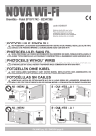
TOUCH Wi-Fi
code ACG3016
Brevettato - Patented EP10711748 - WO2010095160
I
COSTA MECCANICA SENZA FILI
DISPOSITIVO DI PROTEZIONE Wi-Fi PER ORGANI IN MOVIMENTO - CERTIFICATO EN 13849-2 (2008) - Ref. n. 10.027 - CATEGORIA 2
NON POSIZIONARE LA SCHEDA DI GESTIONE MASTER Wi-Fi DIETRO A MURI, PANNELLI METALLICI O
ALTRI TIPI DI OSTACOLI CHE POSSANO IMPEDIRE LA COMUNICAZIONE RADIO CON TOUCH Wi-Fi
F
BARRE PALPEUSE MÉCANIQUE SANS FIL
DISPOSITIF DE PROTECTION Wi-Fi POUR ORGANES EN MOUVEMENT - CERTIFIÉ EN 13849-2 (2008) N. 10.027 CATÉGORIE 2
Batterie AA non incluse - Piles AA non incluses - AA batteries not included
AA Batterien nicht beiliegend - Baterías AA no incluidas
NE PAS POSITIONNEZ LA FICHE DE GESTION MASTER Wi-Fi DERRIÈRE DES MURS, PANNEAUX
MÉTALLIQUES, OU AUTRES TYPES D’OBSTACLES QUI POURRAIENT COMPROMETTRE LA TRANSMISSION
RADIO AVEC TOUCH Wi-Fi.
G
B
MECHANICAL STRIP WITHOUT WIRES
Wi-Fi SAFETY DEVICE FOR PROTECTION FROM MOVING ELEMENTS - CERTIFIED EN 13849-2 (2008) NO. 10.027 CATEGORY 2
DO NOT INSTALL MASTER Wi-Fi RECEIVER CARD BEHIND WALLS, METAL FRAMES OR PANELS, OR
OTHER KIND OF OBSTACLES THAT COULD PREVENT THE PROPER RADIO COMMUNICATION WITH
TOUCH Wi-Fi.
D
MECHANISCHE KONTAKTLEISTE OHNE KABEL
SCHUTZVORRICHTUNG Wi-Fi FÜR KÖRPER IN BEWEGUNG - ZERTIFIZIERT NACH EN 13849-2 (2008) NR. 10.027 KATEGORIE 2
NICHT INSTALLIEREN MASTER Wi-Fi KARTE HINTER MAUERN, METALLPLATTEN ODER ANDERE
ARTEN VON HINDERNISSEN, DIE DEN FUNKVERKEHR MIT TOUCH Wi-Fi BEEINTRÄCHTIGEN KÖNNEN.
E
S
COSTA MECÁNICA SIN CABLES
DISPOSITIVO DE PROTECCIÓN Wi-Fi PARA ÓRGANOS EN MOVIMIENTO - CERTIFICADO EN 13849-2 (2008) N. 10.027 CATEGORÍA 2
NO INSTALAR LA FICHA DE GESTION MASTER Wi-Fi EN UN LUGAR DETRÁS DE LAS PAREDES, DE
PANELES DE METAL O DE OTRO TIPO DE OBSTÁCULOS QUE PUEDAN IMPEDIR LA COMUNICACIÓN
POR RADIO CON TOUCH Wi-Fi.
NO - NEIN !
SI - OUI - YES - JA !
MASTER Wi-Fi
MASTER Wi-Fi
NO - NEIN !
SI - OUI - YES - JA !
MASTER Wi-Fi
MASTER Wi-Fi
ITALIANO pag. 02 / FRANÇAIS pag. 08 / ENGLISH page 14 / DEUTSCH pag. 20 / ESPAÑOL pag. 26
I
CARATTERISTICHE TECNICHE / INSTALLAZIONE
COLLEGAMENTI ELETTRICI
TOUCH Wi-Fi in abbinamento al dispositivo elettronico MASTER Wi-Fi è conforme alla
norma EN13849-2 (2008) e congiuntamente ad un quadro elettronico RIB è un dispositivo
di protezione di Classe 2 atto a garantire la protezione di persone/cose da urti provocati da
organi meccanici in movimento quali cancelli o porte a chiusura automatica. L’ostacolo è
rilevato su tutta la lunghezza del dispositivo in modo assiale e perpendicolare.
Le coste TOUCH Wi-Fi possono essere posizionate ovunque senza la necessità di utilizzare
cavi elettrici.
Il Sistema Wi-Fi (costituito da TOUCH Wi-Fi e MASTER Wi-Fi) opera ad una frequenza di
868,3MHz.
La scheda MASTER Wi-Fi comunica costantemente con le coste TOUCH Wi-Fi e segnala
sempre eventuali impatti o malfunzionamenti.
Ogni TOUCH Wi-Fi ha un proprio codice identificativo interno che la distingue dagli altri
dispositivi.
Il Sistema Wi-Fi è una sicurezza attiva in quanto verifica costantemente il corretto
funzionamento delle TOUCH Wi-Fi e lo stato delle batterie.
Utilizzando i quadri elettronici RIB è possibile eseguire l’autotest del sistema.
Utilizzare attuatori RIB, quadri elettronici RIB dotati di autotest e sicurezze RIB permette di
realizzare un’installazione conforme alle Norme e Direttive Europee in vigore.
Una volta ultimato l’impianto ci si deve sincerare che sia conforme alla norma EN13241-1.
RIB non puó considerarsi responsabile per eventuali danni causati da un uso improprio,
erroneo o irragionevole del prodotto.
BAT
Batterie alcaline 3 x 1,5V (tipo AA cod. ACG9519)
SW2
Microinterruttori di abbinamento e identificazione
J3
Morsetti per collegamento contatto costa meccanica
S2 PROG. TX
Pulsante per programmazione
DL1 (rosso) Segnalazione trasmissione radio
S2
DL1
SW2
ATTENZIONE:
Se viene tolta l’alimentazione del MASTER Wi-Fi per un periodo di tempo
prolungato le coste TOUCH Wi-Fi e le fotocellule NOVA Wi-Fi esauriranno più
velocemente del normale la carica delle loro batterie. Tenere i MASTER Wi-Fi
sempre correttamente alimentati per garantire la durata di 3 anni delle batterie
come dichiarata da RIB.
Se per esempio viene tolta la tensione al cancello tutte le notti, fotocellule e coste
“cercano” ripetutamente il segnale dal MASTER Wi-Fi senza trovarlo e quindi la
durata delle batterie di questi accessori si riduce a meno di un anno.
Eventuali modifiche del prodotto o della configurazione dell’apparato non possono essere
eseguite senza consultare il fabbricante o il suo rappresentante autorizzato.
L’installatore del dispositivo di sicurezza deve fornire all’utilizzatore finale quanto segue:
- i dispositivi di sicurezza devono essere fatti conoscere a tutte le persone appropriate.
- le aree che danno accesso ai dispositivi devono essere tenute libere da ostacoli;
- i requisiti per la pulizia per evitare eventuali accumuli pericolosi di materiale;
- possibili dettagli per una procedura di riavvio da eseguire dopo una fermata di emergenza
o accidentale causata dal sistema di controllo.
BAT
La modifica del progetto o della configurazione dell’apparato senza la consultazione del
fabbricante o del suo rappresentante autorizzato può creare situazioni pericolose.
2
J3
I
TIPOLOGIA DI ARTICOLI PER ASSEMBLAGGIO
Profilo in gomma, disponibile in
confezioni da n° 2 pezzi lunghezza
m7
TOU0001
Morsetto serra-cavo in acciaio
TOU0007
Gruppo inferiore
Coperchio inferiore
Viti per coperchio inferiore
Profilo in alluminio, disponibile in
barre da m 2
TOU0002
TOU0008
Coperchio inferiore
con vite di fissaggio
Cavo in acciaio
TOU0003
TOU0009
Coperchio superiore
con vite di fissaggio
Gruppo superiore
con scheda elettronica
TOU0020
TOU0010
Accessori per il montaggio
del profilo in alluminio
Registro
TOU0021
TOU0011
ISTRUZIONI DI MONTAGGIO
L’installazione del dispositivo deve essere effettuata da persone abilitate ed istruite allo
scopo.
TOUCH Wi-Fi può essere montato solo verticalmente (come in fig. 2 pag. 4) sulla parte
mobile e/o su quella fissa. In entrambi i casi lo scopo è quello di poter evitare uno
schiacciamento/urto.
Le posizioni di fissaggio sono mostrate negli esempi di (fig. 1).
Possibili posizionamenti
Cancello a battente doppia anta
Portone scorrevole
Cancello scorrevole
1
3
I
1 - S vitare la vite di fissaggio del coperchio
superiore ed estrarlo (fig. 2 - part. 1).
- Svitare la vite di tenuta della parte superiore
(fig. 3).
- Sfilare la parte superiore con l’annessa scheda
elettronica (fig. 4).
- Togliere dagli incastri la guida in plastica (fig.
5-6).
- Inserire 3 batterie alcaline tipo AA da 1,5V
facendo attenzione alle polarità (fig. 7).
- Inserire la guida in plastica negli appositi
incastri (fig. 8).
- Identificare e
memorizzare la scheda
elettronica come indicato successivamente.
- Inserire la scheda elettronica con il gruppo
meccanico nel profilo in gomma (fig. 9-10-11).
- Inserire nell’apposita asola presente sul
gruppo meccanico il cavo di acciaio (fig. 12).
- Bloccare il gruppo meccanico al profilo
di alluminio utilizzando la vite allentata in
precedenza (fig. 13).
- Inserire nell’ asola presente sulla levetta il cavo
di acciaio (fig. 14).
*
* A costa assemblata assicurarsi che nel punto
indicato non vi siano aperture. Il profilo in
gomma deve aderire al gruppo superiore
evitando infiltrazioni di acqua o insetti.
2
3
4
5
6
7
8
4
I
9
10
11
12
13
14
2 - V erificare che la vite del morsetto di bloccaggio cavo in acciaio sia serrata con forza
(fig. 15).
3 - C
ontrollare che la leva prema il finecorsa centrale. Qualora non fosse così, allentare il
dado di bloccaggio registro e regolare il registro per portare la rotella in posizione (fig.
16).
4 - S vitare le viti di fissaggio del coperchio inferiore ed estrarlo (fig. 2 - part. 2).
5 - S egnare la posizione (S) del lato superiore dell’asola di fissaggio sul lato della barra di
alluminio (fig. 2 - part. 3).
6 - P osizionare TOUCH Wi-Fi sulla parete e segnare la posizione corrispondente al
riferimento segnato in precedenza. Nel montaggio verticale mantenere una distanza
minima dal terreno di 30 mm orientando il dispositivo come in fig. 2 - part. 2.
7 - F orare il piano di supporto costa circa 7 mm sotto il riferimento e fissare la molla di
ritegno con gli elementi opportuni, vite per metallo o vite e tassello ad espansione per
muratura (fig. 2 - part. 4).
8 - P osizionare TOUCH Wi-Fi sulla molla di ritegno ed agganciarla tirandola verso il basso.
9 - C
ontrassegnare i fori di fissaggio sulla parete in corrispondenza di -C- e -D- (fig. 2 part 1 e 2).
10 - T ogliere il dispositivo ed eseguire i fori di fissaggio segnati in precedenza.
11 - R iagganciare il dispositivo sulla molla e procedere con il fissaggio delle viti.
15
Dado di bloccaggio registro
Posizione del rullino sul finecorsa centrale
5
16
I
12 - Inserire il coperchio inferiore nell’incastro e fissarlo con le viti (fig. 17).
13 - Inserire il coperchio superiore e fissarlo con la vite.
14 - Controllare il funzionamento della TOUCH Wi-Fi come descritto nel paragrafo “VERIFICA
DEL CORRETTO FUNZIONAMENTO”.
Inserimento
17
IDENTIFICAZIONE
Ogni TOUCH Wi-Fi viene fornito con i microinterruttori in posizione OFF per evitare lo
scaricamento delle batterie quando non viene utilizzato (se collegate).
Ogni TOUCH Wi-Fi deve essere OBBLIGATORIAMENTE univocamente identificata
mettendo su ON uno solo dei sei microinterruttori (SW2).
Si deve posizionare su ON solo uno dei 6 microinterruttori e l’identificazione deve essere
diversa per ogni TOUCH Wi-Fi.
Nota: IDENTIFICARE I CONTENITORI DELLE TOUCH Wi-Fi APPLICANDO L’ADESIVO
NUMERATO (IN DOTAZIONE) ALL’ESTERNO DI OGNI CONTENITORE.
L’identificazione dei contenitori serve per sostituire velocemente le batterie scariche di
TOUCH Wi-Fi indicata dai led EDGE della scheda MASTER Wi-Fi.
OFF
12345 6
ON
12345 6
ESEMPIO DI IDENTIFICAZIONE DI
UNA COSTA TOUCH Wi-Fi SU MASTER Wi-Fi
6
6
6
6
6
6
5
5
5
5
5
5
4
4
4
4
4
4
3
3
3
3
3
3
2
2
2
2
2
2
1
1
1
1
1
1
MASTER Wi-Fi
ESEMPIO DI IDENTIFICAZIONE DI
3 COSTE TOUCH Wi-Fi SU MASTER Wi-Fi
ON
TOUCH Wi-Fi 1
MASTER Wi-Fi
MEMORIZZAZIONE
ON
TOUCH Wi-Fi 1
PROG RX
Dopo avere eseguito l’identificazione delle TOUCH Wi-Fi, spostare su ON i microinterruttori
corrispondenti su MASTER Wi-Fi e procedere alla memorizzazione dei codici delle TOUCH
Wi-Fi:
- Premere il pulsante PROG RX che si trova su MASTER Wi-Fi=> il led bicolore EDGE PHOT
1 sarà rosso lampeggiante per 1 minuto (tempo utile per eseguire la memorizzazione).
- Premere il tasto PROG TX su TOUCH Wi-Fi con microinterruttore 1 su ON => su MASTER
Wi-Fi il led bicolore EDGE PHOT 1 da rosso lampeggiante diventa verde e un tono di buzzer
segnala la corretta memorizzazione di TOUCH Wi-Fi, subito dopo si accende lampeggiante
rosso il led bicolore EDGE PHOT 2 lampeggiando per 1 minuto (tempo utile per eseguire
la memorizzazione).
- Se non vengono memorizzate altre TOUCH Wi-Fi lasciare trascorrere un minuto ed il
led bicolore EDGE PHOT 2 si spegnerà oppure premere il tasto PROG. RX per 4 volte
per terminare la procedura di memorizzazione => tutti i led bicolore EDGE PHOT devono
risultare spenti.
TOUCH Wi-Fi 2
TOUCH Wi-Fi 3
LED BICOLORE 1
12/24V ac/dc
6
I
PER MEMORIZZARE ALTRE TOUCH Wi-Fi
- Premere il tasto PROG. TX di TOUCH Wi-Fi con microinterruttore 2 su ON => su MASTER
Wi-Fi il led bicolore EDGE PHOT 2 da rosso lampeggiante diventa verde lampeggiante e un
tono di buzzer segnala la corretta memorizzazione di TOUCH Wi-Fi .
- Eseguire la stessa procedura per eventuali altre TOUCH Wi-Fi (fino ad un massimo di 6).
Anche il led DL2 si spegnerà indicando l’avvenuta interruzione del contatto dedicato
all’ingresso EDGE sul quadro di comando del motore.
- Ripetere la verifica per tutte le TOUCH Wi-Fi installate.
Eseguire una verifica funzionale di tutte le TOUCH Wi-Fi installate attivando la movimentazione
dell’automazione e controllando che all’impatto con la costa l’automazione fermi/inverta il
movimento.
VERIFICA DEL CORRETTO FUNZIONAMENTO
Terminata la procedura di memorizzazione, verificare il corretto funzionamento tra TOUCH
Wi-Fi e MASTER Wi-Fi nel seguente modo:
- Verificare che premendo la costa TOUCH Wi-Fi con dip 1 ON, il corrispondente led bicolore
EDGE PHOT 1 sulla scheda MASTER Wi-Fi si accenda di colore verde per la durata della
pressione.
IN CASO DI DIFFICOLTA’
SINTOMO
VERIFICA
La costa non funziona
Verificate lo stato delle batterie e del contatto
PER ALTRE INFORMAZIONI FATE RIFERIMENTO AL LIBRETTO ISTRUZIONI DELLA SCHEDA MASTER Wi-Fi
CARATTERISTICHE TECNICHE ELETTRONICHE
MANUTENZIONE PERIODICA
TOUCH Wi-Fi è certificata EN13849-2 2008 - ref. n. 10.027 - categoria 2
FREQUENZA
868,3 MHz
-108 dBm
SENSIBILITA’
POTENZA DI EMISSIONE
<25 mW
ALIMENTAZIONE
batterie 3 x AA 1,5 V (> 2,7 Ah)
25 µA
ASSORBIMENTO A RIPOSO
ASSORBIMENTO MASSIMO
13 mA
FSK
TIPO DI MODULAZIONE PORTATA 20 m in spazio libero senza antenna
VITA DELLA/E BATTERIE
3 anni (tipo AA)
0,5 A - 24 V c.a. c.c.
PORTATA DEI CONTATTI
TEMPERATURA DI LAVORO
-20°C ÷ +60°C
IP44
GRADO DI PROTEZIONE
GRADO DI UMIDITÀ RELATIVA
<93%
Deve essere effettuata solo da personale autorizzato in accordo con le regole di sicurezza e
con le istruzioni del fabbricante, con frequenza semestrale.
- La costa TOUCH Wi-Fi deve essere mantenuta in condizioni di lavoro efficienti e in accordo
con le istruzioni del fabbricante.
- Sostituire le batterie quando richiesto dal sistema (si veda tabella “in caso di difficoltà” su
manuale MASTER Wi-Fi).
- Verificare la presenza e la leggibilità della marcatura iniziale.
- Le parti usurabili sono segnalate nella tabella ”Tipologia di articoli per l’assemblaggio”;
eventuali sostituzioni devono essere eseguite da tecnico abilitato seguendo le istruzioni di
montaggio e verifica.
1 - Verificare che i coperchi (superiore e inferiore) e il supporto in alluminio siano integri e
non deformati; verificare che la parte in gomma sia integra e non lacerata.
2 - Smontare il coperchio.
3 - Controllare il cavo di acciaio che sia integro e non sfilacciato; sostituire il cavo in caso
contrario.
4 - Controllare che, in condizioni di riposo, la leva sia posizionata sul finecorsa centrale. In
caso contrario regolare la posizione agendo sulla vite di regolazione.
5 - Controllare l’integrità del coperchio superiore e sostituirlo se danneggiato.
6 - Verificare che non siano presenti tracce di umidità o corpi estranei e rimuoverli in caso
contrario.
7 - Tenendo premuto il contatto del finecorsa centrale, premere la gomma e controllare che
il circuito elettrico venga interrotto.
8 - Rilasciare il bordo di gomma e controllare che il contatto elettrico si ripristini.
9 - Rimontare il coperchio.
CARATTERISTICHE TECNICHE MECCANICHE
CORSA DAL CONTATTO ALL’INTERVENTO (PRECORSA)
max 15 mm
CORSA DALL’INTERVENTO ALLA BATTUTA MECCANICA (EXTRACORSA) min. 40 mm
TEMPO DI APERTURA DEI CONTATTI DALL’INTERVENTO
max 0,1 s
max 0,5 s
TEMPO DI RECUPERO DALLA DEFORMAZIONE MASSIMA
FORZA MASSIMA APPLICABILE AL DISPOSITIVO
max 1 KN
MASSIMA VELOCITÀ DEL DISPOSITIVO IN MOVIMENTO
max 0,25 m/s *
* L ’utilizzo con operatori con velocità superiore a 0,25 m/s (15 m/min) determina un mancato rispetto
della normativa in vigore.
OPTIONAL
BATTERIE ALCALINE AA
BATTERIE LITHIO AA
4 X 1,5V - con TOUCH Wi-Fi durata batterie 3 anni.
2 X 1,5V - con TOUCH Wi-Fi durata batterie 4 anni (prendere 2 pezzi).
Per temperature estreme -40÷+60°C.
cod. ACG9509
cod. ACG9519
7
F
CARACTERISTIQUES TECHNIQUES / INSTALLATION
RACCORDEMENTS ÉLECTRIQUES
TOUCH Wi-Fi est conforme à la norme EN13849-2 (2008) s’il est conjointement utilisé avec
MASTER Wi-Fi.
TOUCH Wi-Fi, s’il est utilisé avec un tableau électrique de la marque RIB, constitue un
dispositif de protection de classe 2. Son but est de protéger les personnes/objets d’un
quelconque choc qui proviendrait d’appareils mécaniques en mouvement comme des
portails ou des portes à fermeture automatique.
L’obstacle est détecté sur toute la longueur du dispositif, parallèlement et perpendiculairement.
Les barres palpeuses TOUCH Wi-Fi peuvent être positionnées partout et ne nécessitent pas
l’utilisation de fils électriques.
Le système Wi-Fi (constitué de TOUCH Wi-Fi et de MASTER Wi-Fi) fonctionne à une
fréquence de 868,3 MHz.
La carte MASTER Wi-Fi est constamment en contact avec les barres palpeuses TOUCH Wi-Fi
et signale automatiquement les impacts ou dysfonctionnements éventuels.
Chaque TOUCH Wi-Fi possède un code d’identification interne unique qui le distingue des
autres dispositifs.
Le Système Wi-Fi constitue une sécurité active car il vérifie constamment le bon
fonctionnement des TOUCH Wi-Fi et l’état des piles.
Il est possible d’effectuer des contrôles automatiques du système en utilisant des tableaux
électriques RIB.
L’utilisation d’actionneurs RIB, de tableaux électriques RIB dotés de test automatique et
de sécurités RIB permet de réaliser une installation conforme aux normes et directives
européennes en vigueur.
Une fois l’installation terminée, il faut s’assurer qu’elle soit conforme à la norme EN13241-1.
RIB ne peut être tenu responsable d’éventuels dommages résultant d’une utilisation
impropre, inadéquate ou irresponsable du produit.
BAT
Piles alcalines 3 x 1,5 V (modèle AA code ACG9519)
SW2
Micro-interrupteurs de couplage et d’identification
J3
Pinces pour le raccordement de la barre palpeuse mécanique
S2 PROG TX
Touche pour la programmation
DL1 (rouge)
Signal de transmission radio
S2
DL1
SW2
ATTENTION
Si vous avez enlevée l’alimentation du MASTER Wi-Fi pour une période de
temps rallongé, les barre palpeuse TOUCH Wi-Fi et les photocellules NOVA Wi-Fi
termineront plus rapidement du normal la charge de leurs batteries.
Gardez les MASTER Wi-Fi toujours correctement alimentés, pour garantir la durée
de 3 ans des batteries, comme déclarée de RIB.
Par exemple, si l’alimentation est coupée à la grille toutes les nuits, les
photocellules et les cordons “essaient” à plusieurs reprises sans trouver le signal
du MASTER Wi-Fi et l’autonomie des batteries de ces accessoires peut être
réduite à moins d’un an.
Des eventuelles modifications de produit ou de la configuration de l’appareil ne peuvent pas
être exécutées sans consulter le fabricant ou son représentant autorisé.
L’installateur du dispositif de sûreté doit fournir à l’utilisateur final tout ce qui suit:
- les dispositifs de sûreté doivent être connus de toutes les personnes appropriées;
- les aires qui donnent accès aux dispositifs doivent être tenues libres d’obstacles;
- les qualités pour le nottoyage à éviter eventuelles accumulations dangereuses de
matériel;
- possibles spécifications pour une procédure de renvoi à exécuter après une arrêtée
d’émergence ou accidentelle causée du système de contrôle.
BAT
La modification du projet ou de la configuration de l’appareil sans la consultation du fabricant
ou de son représentant autorisé peut créer des situations dangereuses.
8
J3
F
TYPOLOGIE DES ARTICLES POUR ASSEMBLAGE
Profile en caoutchouc,
disponible en paquets de
2 pièces, longueur m 7
Borne serre-câble en acier
TOU0001
TOU0007
Groupe inférieur
Couvercle inférieur
Vis pour couvercle inférieur
Profile en aluminium,
disponible en barres de
m2
TOU0002
TOU0008
Couvercle inférieur avec vis
de fixation
Câble en acier
TOU0003
TOU0009
Couvercle supérieur avec
vis de fixation
Groupe supérieur avec carte
électronique
TOU0020
TOU0010
Accessoires pour le montage
du profile en aluminium
Registre
TOU0021
TOU0011
INSTRUCTIONS POUR LE MONTAGE
L’installation du dispositif doit être effectuée par du personnel qualifié.
TOUCH Wi-Fi peut être installé seulement verticalement (comme en fig. 2 pag. 10) sur la
partie mobile et/ou sur la partie fixe.
Dans les deux cas, le but est d’éviter un écrasement/choc.
Les positions de fixation sont illustrées dans les exemples (fig. 1).
Positionnements possibles
Portail battant à deux vantaux
Porte coulissante
Portail coulissant
1
9
F
1 - D
évisser la vis de fixation de l’embout
supérieur et l’extraire (fig. 2 - 1 partie)
- Dévisser la vis de blocage de la partie
supérieure (fig. 3)
- Enlever la partie supérieure ainsi que la carte
électronique (fig. 4)
- Extraire le profilé en plastique (fig. 5-6)
- Insérer 3 piles alcalines de type AA de 1,5V
en faisant attention à la polarité (fig. 7).
- Insérer le profilé conducteur en plastique
dans l’emplacement réservé (fig. 8)
- Identifier et mémoriser la carte électronique
comme expliqué ci-après.
- Insérer la carte électronique et le groupe
mécanique dans le profilé en caoutchouc
(fig. 9-10-11).
- Insérer le câble en acier dans la fente
présente sur le groupe mécanique (fig. 12)
- Bloquer le groupe mécanique sur le profilé
en aluminium en utilisant la vis desserrée
précédemment (fig. 13)
- Insérer le câble d’acier dans la fente présente
sur le levier (fig. 14)
*
Quand on a assemblé le bord, il faut
s’assurer qu’il n’y a pas d’ouvertures dans
le point indiqué. Le profil en gomme et
les parties au dessus doivent adhérer, afin
d’éviter des infiltrations d’eau ou d’insectes.
*
2
3
4
5
6
7
8
10
F
9
10
11
12
13
14
2 - V érifier que la vis de la borne serre-câble en acier soit bien serrée (fig. 15).
ontrôler que le levier fasse pression sur la butée centrale. Si ce n’est pas le cas,
3 - C
desserrer le boulon de blocage du registre pour que la rondelle soit dans la bonne
position (fig. 16).
4 - D
évisser les vis de fixation de l’embout inférieur et l’enlever (fig.2 - part. 2).
5 - M
arquer la position (S) du trait supérieur de la fente de fixation sur le côté du profilé
en aluminium (fig. 2 - part. 3)
6 - P ositionner TOUCH Wi-Fi sur le mur et marquer l’emplacement correspondant à la
marque effectuée précédemment. Dans le montage vertical, maintenir une distance
minimale de 30 mm du sol en orientant le dispositif comme montré dans la figure
2 - part. 2.
7 - P ercer le plan de support de la barre palpeuse environ 7 mm sous la marque et fixer
le ressort de retenue avec les éléments adéquats, tels que des vis à métaux ou un
assemblage vis/cheville pour maçonnerie (fig. 2 - part. 4)
8 - P ositionner TOUCH Wi-Fi sur le ressort de retenue et l’accrocher en le tirant vers le
bas.
9 - M
arquer les points de fixation sur le mur pour C et D (fig. 2 - part. 1 et 2)
10 - Ô
ter le dispositif et faire les trous pour la fixation, suivant les marquages effectués
précédemment.
11 - A ccrocher de nouveau le dispositif sur le ressort et fixer les vis.
15
Ecrou de blocage registre
Position du rouleau sur la butée central
11
16
F
12 - Insérer l’embout inférieur dans l’emplacement et le fixer avec les vis (fig. 17).
13 - Insérer l’embout supérieur et le fixer avec la vis.
14 - Contrôler le fonctionnement du TOUCH-Wifi comme expliqué dans la section «
CONTROLE DU FONCTIONNEMENT »
Introduction
17
IDENTIFICATION
Chaque TOUCH Wi-Fi est livré avec les micro-interrupteurs en position OFF par défaut pour
éviter que les piles se déchargent quand il n’est pas utilisé (si celles-ci sont insérées).
Chaque TOUCH Wi-Fi doit OBLIGATOIREMENT être identifié de manière unique en
positionnant un seul des six micro-interrupteurs (SW2) sur ON.
Il ne faut positionner sur ON qu’un seul des 6 micro-interrupteurs et l’identification doit être
différente pour chaque TOUCH Wi-Fi.
Remarque: IDENTIFIER LES BOITIERS DES TOUCH Wi-Fi EN POSANT UNE ETIQUETTE
NUMÉROTÉE (FOURNIE) SUR CHAQUE BOITIER.
L’identification des boitiers est utile pour remplacer rapidement les piles déchargées de
TOUCH Wi-Fi. Leur décharge est indiquée par les LED de la carte MASTER Wi-Fi.
OFF
12345 6
ON
12345 6
EXEMPLE D’IDENTIFICATION D’UNE BARRE PALPEUSE
TOUCH Wi-Fi SUR MASTER Wi-Fi
6
6
6
6
6
6
5
5
5
5
5
5
4
4
4
4
4
4
3
3
3
3
3
3
2
2
2
2
2
2
1
1
1
1
1
1
MASTER Wi-Fi
EXEMPLE D’IDENTIFICATION
DE 3 BARRES PALPEUSES TOUCH Wi-Fi SUR MASTER Wi-Fi
ON
TOUCH Wi-Fi 1
MASTER Wi-Fi
MEMORISATION
ON
TOUCH Wi-Fi 1
PROG RX
Après avoir effectué l’identification des TOUCH Wi-Fi, basculer les micro-interrupteurs
correspondants sur ON sur le MASTER Wi-Fi et poursuivre avec la mémorisation des codes
des TOUCH Wi-Fi :
- Appuyer sur la touche PROG RX sur le MASTER Wi-Fi => La LED bicolore EDGE PHOT 1
clignotera rouge pendant 1 minute (le temps nécessaire pour effectuer la mémorisation).
- Appuyer sur la touche PROG TX sur le TOUCH Wi-Fi avec le micro-interrupteur 1 sur
ON => La LED bicolore EDGE PHOT 1 sur le MASTER Wi-Fi passe de rouge clignotant à
vert et un bip signale que la mémorisation a été correctement effectuée. Ensuite, la LED
bicolore EDGE PHOT 2 se met à clignoter rouge pendant 1 minute (le temps nécessaire
pour effectuer la mémorisation).
- Si d’autres TOUCH Wi-Fi ne doivent pas être mémorisées, attendre une minute et la LED
bicolore EDGE PHOT 2 s’éteindra ou appuyez 4 fois sur PROG RX pour finir le processus de
mémorisation => toutes les LED bicolores EDGE PHOT devraient s’éteindre.
12
TOUCH Wi-Fi 2
TOUCH Wi-Fi 3
LED BICOLORE 1
12/24V ac/dc
F
POUR MÉMORISER D’AUTRES TOUCH Wi-Fi
- Appuyer sur le bouton PROG TX du TOUCH Wi-Fi avec le micro-interrupteur 2 sur ON =>
La LED bicolore EDGE PHOT 2 passe de rouge clignotant à vert clignotant sur le MASTER
Wi-Fi et un bip signale que la mémorisation du TOUCH Wi-Fi a été correctement effectuée.
- Effectuer la même procédure pour d’éventuels autres TOUCH Wi-Fi (au maximum 6).
CONTROLE DU FONCTIONNEMENT
L a LED DL2 s’éteindra pour signaler l’interruption du contact EDGE sur le tableau de
commande du moteur.
- Répéter la vérification pour tous les TOUCH Wi-Fi installés.
Faire un test de fonctionnement de tous les TOUCH Wi-Fi installés en activant le mouvement
de l’automatisme et en contrôlant que lors du contact avec la barre palpeuse, le mouvement
s’arrête/s’inverse.
Une fois que le processus de mémorisation est terminé, vérifier que le fonctionnement soit
correct entre le TOUCH Wifi et le MASTER Wifi de la manière suivante:
- Vérifier qu’en appuyant sur la barre palpeuse TOUCH Wi-Fi avec l’interrupteur 1 en position
ON, la LED bicolore correspondante EDGE PHOT 1 sur la carte MASTER Wi-Fi s’allume en
vert tant que l’on reste appuyé.
EN CAS DE PROBLÈME
PROBLÈME
VERIFICATION
La barre palpeuse ne fonctionne pas
Vérifiez l’état des piles et du contact
POUR DE PLUS AMPLES INFORMATIONS, REFEREZ VOUS AU MANUEL D’INSTRUCTIONS DE LA CARTE MASTER Wi-Fi.
CARACTÉRISTIQUES TECHNIQUES ÉLECTRONIQUES
Il doit être effectué seulement de personnel autorisé en accord avec les règles de sûreté et
avec les instructions du fabricant, avec la fréquence semestrielle.
CERTIFIÉ EN 13849-2 (2008) N. 10.027 CATÉGORIE 2
FRÉQUENCE
868,3 MHz
SENSIBILITÉ
-108 dBm
<25 mW
PUISSANCE D’ÉMISSION
ALIMENTATION
piles 3 x AA 1,5 V (>2,7 Ah)
25 µA
CONSOMMATION EN VEILLE
CONSOMMATION MAXIMALE
13 mA
TYPE DE MODULATION FSK
20 m dans l’air sans antenne
PORTÉE DURÉE DE VIE DE LA/ DES PILE(S) 3 Ans (modèle AA)
PORTÉE DES CONTACTS
0,5 A - 24 V c.a. c.c.
TEMPÉRATURE DE FONCTIONNEMENT -20°C ÷ +60°C
DEGRÉ DE PROTECTION
IP44
<93%
DEGRÉ D’ HUMIDITÉ RELATIVE
- Le barre palpeuse TOUCH WI-Fi doit être maintenu en conditions de travail efficaces et en
accord avec les instructions du fabricant.
- Substituer les batteries lorsque demandé du système (voir tableau EN CAS DE DIFFICULTÉ
sur manuel MASTER Wi-Fi).
- Vérifier la présence et la lisibilité du marquage initial.
- Les parties à usure sont signalées dans le tableau “Typologie d’articles pour l’assemblage”;
les eventuelles substitutions doivent être exécutées du technicien certifié, en suivant les
instructions de montage et contrôle.
CARACTÉRISTIQUES TECHNIQUES MÉCANIQUES
COURSE DU CONTACT A L’INTERVENTION (DEMARRAGE)
max 15 mm
COURSE DE L’INTERVENTION A LA BUTÉE MÉCANIQUE (DEPASSEMENT) min. 40mm
DURÉE D’OUVERTURE DES CONTACTS A PARTIR DE L’INTERVENTION max 0,1 s
DURÉE DE RÉCUPÉRATION A PARTIR DE LA DÉFORMATION MAXIMALE max 0,5 s
max 1 KN
FORCE MAXIMALE APPLICABLE SUR LE DISPOSITIF
VITESSE MAXIMALE DU DISPOSITIF EN MOUVEMENT
max 0,25 m/s *
* L ’utilisation avec des opérateurs possédant une vitesse supérieure à 0,25 m/s (15m/min) constitue un
1 - Vérifier que les embouts (supérieur et inférieur) et le support en aluminium soient intacts
et non déformés; vérifier que la partie en caoutchouc ne soit ni abimée ou déchirée.
2 - Démonter l’embout
3 - Vérifier que le câble en acier soit intact. Si ce n’est pas le cas, le remplacer.
4 - En veille, vérifier que le levier soit positionné sur la butée centrale. Dans le cas contraire,
ajuster la position en agissant sur la vis de réglage.
5 - Vérifier que l’embout supérieur soit intact. Sinon le remplacer.
6 - Vérifier qu’il n’y ait pas de trace d’humidité ou de corps étranger. Les enlever s’il y en a.
7 - En maintenant appuyé le contact de la butée centrale, presser le caoutchouc et vérifier
que le circuit électrique soit interrompu.
8 - Relâcher la barre palpeuse et vérifier que le contact électrique soit rétabli.
9 - Remettre l’embout.
non- respect des normes en vigueur.
ENTRETIEN RÉGULIER
OPTIONS
BATTERIES ALCALINES AA
BATTERIES LITHIO AA
4 X 1,5V - avec TOUCH Wi-Fi vie batteries 3 ans.
code ACG9519
2 X 1,5V - avec TOUCH Wi-Fi vie batteries 4 ans (prendre 2 pièces).
Pour des températures extrêmes -40÷+60°C.
13
code ACG9509
G
B
TECHNICAL DATA / INSTALLATION
TOUCH Wi-Fi in combination with the electronic device MASTER Wi-Fi conforms to standard
EN13849-2 (2008) and when used with a RIB electronic control panel it is a Class 2
protection device for protecting persons/things from collisions caused by mechanical moving
parts such as automatic gates or doors. The obstacle is detected along the entire length of
the device axially and perpendicularly.
The TOUCH Wi-Fi strips can be positioned anywhere without needing to use electrical wire.
The WiFi system (made up of a TOUCH Wi-Fi and MASTER Wi-Fi) operate at a frequency
of 868,3 MHz.
The MASTER Wi-Fi card communicates constantly with the TOUCH Wi-Fi strips and always
signals collisions or malfunctions.
Each TOUCH Wi-Fi has its own internal ID code that distinguishes it from the other devices.
The WiFi system is an active security system because it constantly verifies proper functioning
of the TOUCH Wi-Fi devices and battery condition.
When using RIB electronic control panels you can run auto-tests on the system.
With RIB actuators, RIB electronic control panels having the auto-test function and RIB
safety devices you can create an installation that conforms to the European Directives and
Norms in force.
After completing the system, you must make sure it conforms to standard EN13241-1.
RIB shall not be liable for any damages caused by improper, incorrect or unreasonable use
of the product.
ELECTRICAL CONNECTIONS
BAT
Alkaline batteries 3 x 1.5V (type AA code ACG9519)
SW2
Microswitches for combination and identification
J3
Terminals for connecting to mechanical strip contact
S2 PROG. TX
Programming pushbutton
DL1 (red) Radio transmission signal
S2
DL1
SW2
ATTENTION:
If you remove the power of the MASTER Wi-Fi for a long time, the TOUCH Wi-Fi
safety strips and the NOVA Wi-Fi photocells will exhaust faster than normal the
charging of their batteries. Keep the MASTER Wi-Fi always properly fed to ensure
a period of three years for the batteries-life, as stated by RIB.
If for instance, the power to the system is cut off every night, the photocells
and the safety strips will regularly and constantly search for the MASTER Wi-Fi
without finding it. Therefore, the life span of the batteries may be reduce to less
than one year.
Any possible modification of the device, or of the configuration of the same cannot be carried
out without the clear authorization by the manufacturer or, by the local authorized dealer.
The installer of the safety device must make sure that the end user know the following:
- That the safety devices must be made known to all appropriate people.
- That the passages to reach the devices must be kept clear from any obtsacle.
- About the procedures for cleaning so to avoid the dangerous building up of material.
- The possible details for a restart of the system after an emergency or accidental stop
caused by the control system.
Any modification of the project or, of the configuration of the device, without discussing it
first with the manufacturer or with the local autorized dealer can cause dangerous situations.
14
BAT
J3
G
B
TYPE OF ITEMS FOR ASSEMBLY
Rubber profile available
in packages of n° 2 items
7 m length
Steel flat connector
TOU0001
TOU0007
Lower group
Lower cover
Screws for lower cover
Aluminium profile available
in strips from 2 m
TOU0002
TOU0008
Lower cover with fastening
screws
Steel cable
TOU0003
TOU0009
Upper cover with fastening
screws
Upper assembly with electronic board
TOU0020
TOU0010
Accessories for assembling
Aluminium profile
Register
TOU0021
TOU0011
ASSEMBLY INSTRUCTIONS
The device must be assembled by qualified people trained specifically for this purpose.
TOUCH Wi-Fi can be mounted only vertically (as per pitc. 2 page 16) on the moving
part and/or the fixed part. In both cases the purpose is to avoid crushing/collision.
The fastening positions are shown in the examples in Fig. 1.
Possible positions
Double leaf swing gate systems
Sliding door systems
Sliding gate systems
1
15
G
B
1 -Unscrew fastening screws of upper cover and
remove it (fig. 2 - part. 1).
- Unscrew gland bolts from upper part (fig. 3).
- Remove upper part complete with the adjacent
electronic board(fig. 4).
- Remove plastic guide from notches (fig. 5-6).
- Insert 3 alkaline type AA with batteries 1.5V
and pay attention to the polarities (fig. 7).
- Insert plastic guide into notches fig. 8).
- Identify and memorize electronic board as
indicated below.
- Insert electronic card with mechanical
assembly into rubber profile (fig. 9-10-11).
- Insert steel cable into appropriate slot on
mechanical assembly (fig. 12).
- Lock mechanical assembly to aluminum profile
using screws loosened previously (fig. 13).
- Insert steel cable into slot located on lever (fig.
14).
*
* Once the safety edge is fixed, make sure
there are no gaps in between the parts
indicated.The rubber profile and the parts
above it, must perfectly adhere to avoid the
passage of rain or insects.
2
3
4
5
6
7
8
16
G
B
9
10
11
12
13
14
2 - M
ake sure screw on steel cable clamp is tightened securely using force (fig. 15).
ake sure lever presses the central limit switch. If it does not, loosen locknut that
3 - M
locks the adjuster and regulate the adjuster until the castor reaches the proper position
(fig. 16).
4 - U nscrew fastening screws of lower cover and remove it (fig. 2 - part. 2).
5 - M
arks position (S) on upper side of fastening slot on the side of the aluminum bar (fig.
2 - part. 3).
6 - P osition TOUCH Wi-Fi on the wall and mark the position corresponding to the reference
marked previously. In cases of vertical assembly, keep a minimum distance from the
ground of 30 mm and aim the device as shown in fig. 2 - part. 2.
7 - P erforate strip support surface about 7 mm under reference mark and fasten retention
spring with appropriate elements: screws for metal or screws and anchor bolts for
masonry (fig. 2 - part. 4).
8 - P osition TOUCH Wi-Fi on retention spring and hook it by pulling it downward.
9 - M
ark fastening holes on wall in correspondence to -C- and -D- (fig. 2 - part 1 and 2).
10 - R emove device and drill fastening holes marked previously.
11 - H
ook device to spring again and tighten screws.
15
Regulation check nut
Position the roller on central micro-switch pin
17
16
G
B
12 - Insert lower cover into notch and fasten with screws (fig. 17).
13 - Insert upper cover and fasten with screws.
14 - Check functioning of TOUCH Wi-Fi as described under the paragraph of “CHECK
PROPER FUNCTIONING”.
Insertion
17
IDENTIFICATION
Each TOUCH Wi-Fi is supplied with microswitches in the OFF position to prevent batteries
from becoming discharged when not in use (if connected).
Each TOUCH Wi-Fi must be ABSOLUTELY unequivocally identified by putting only one of
the six microswitches in the ON position (SW2).
Only one of the six microswitches must be in the ON position and the identification must be
different for each TOUCH Wi-Fi.
Note: IDENTIFY TOUCH Wi-Fi CONTAINERS BY APPLYING NUMBERED ADHESIVE LABEL
(SUPPLIED) ON OUTSIDE OF EACH CONTAINER.
Identification of containers serves to rapidly replace dead batteries in TOUCH Wi-Fi indicated
by EDGE LED on MASTER Wi-Fi card.
OFF
12345 6
ON
12345 6
EXAMPLE OF IDENTIFICATION OF A TOUCH Wi-Fi
STRIP ON A MASTER Wi-Fi
6
6
6
6
6
6
5
5
5
5
5
5
4
4
4
4
4
4
3
3
3
3
3
3
2
2
2
2
2
2
1
1
1
1
1
1
MASTER Wi-Fi
EXAMPLE OF IDENTIFICATION OF 3 TOUCH Wi-Fi STRIPS
ON A MASTER Wi-Fi
ON
TOUCH Wi-Fi 1
MASTER Wi-Fi
MEMORIZATION
ON
TOUCH Wi-Fi 1
PROG RX
After identifying the TOUCH Wi-Fi, put the microswitches corresponding to the MASTER
Wi-Fi in the ON position and memorize the codes of the TOUCH Wi-Fi:
- Press the PROG RX key located on the MASTER Wi-Fi=> the bicolor EDGE PHOT 1 LED will
flash red for one minute (the time needed to execute memorization).
- Press the PROG TX key on the TOUCH Wi-Fi with microswitches 1 set to ON => on the
MASTER Wi-Fi the bicolor EDGE PHOT 1 LED flashing red will become green and a buzzer
will signal that memorization of the TOUCH Wi-Fi is correct, after which the bicolor EDGE
PHOT 2 LED immediately starts flashing red for one minute (time needed to execute
memorization) l.
- If other TOUCH Wi-Fi are not memorized, let one minute pass and the bicolor EDGE PHOT
2 LED turns off; or press the PROG. RX key four times to end the memorization procedure
=> all bicolor EDGE PHOT LEDs must be off.
18
TOUCH Wi-Fi 2
TOUCH Wi-Fi 3
BICOLOR LED 1
12/24V ac/dc
G
B
TO MEMORIZE OTHER TOUCH Wi-Fi
- Press the PROG. TX key of the TOUCH Wi-Fi with microswitch 2 turned ON => on MASTER
Wi-Fi the bicolor EDGE PHOT 2 LED turns from flashing red to flashing green and a buzzer
tone sounds to indicate proper memorization of the TOUCH Wi-Fi .
- Perform the same procedure for any other TOUCH Wi-Fi (up to a maximum of 6).
T he DL2 LED will turn off to indicate interruption of the contact dedicated to the EDGE input
on the motor control panel.
- Repeat the check on all the installed TOUCH Wi-Fi.
Run a functional check on all the installed TOUCH Wi-Fi by activating the motion of the
automation and check that, upon collision with the strip, the automation stops/inverts its
motion.
CHECKING PROPER FUNCTIONING
After the memorization procedure, check proper functioning between the TOUCH Wi-Fi and
the MASTER Wi-Fi as follows:
- Make sure that when you press the TOUCH Wi-Fi strip with dip 1 ON, the corresponding
bicolor EDGE PHOT 1 LED on the MASTER Wi-Fi Board turns red for the duration of the
pressing action.
IN CASES OF DIFFICULTY
PROBLEM
CHECK
The strip does not work
Check condition of batteries and contact
FOR OTHER INFORMATION REFER TO THE INSTRUCTION BOOKLET OF THE MASTER Wi-Fi CARD
ELECTRONIC TECHNICAL CHARACTERISTICS
ROUTINE MAINTENANCE
CERTIFIED EN 13849-2 (2008) NO. 10.027 CATEGORY 2
FREQUENCY
868,3 MHz
-108 dBm
SENSITIVITY
OUTPUT POWER
<25 mW
POWER SUPPLY
3 type AA batteries 1.5 V (> 2.7 Ah)
25 µA
INPUT AT REST
MAXIMUM INPUT 13 mA
FSK
MODULATION TYPE CAPACITY 20 m in free space without antenna
BATTERY LIFE
3 years (type AA)
0,5 A - 24 V c.a. c.c.
CAPACITY OF CONTACTS
WORKING TEMPERATURE
-20°C ÷ +60°C
IP44
DEGREE OF PROTECTION
DEGREE OF RELATIVE HUMIDITY <93%
Must be carried out every six months, only by authorized personnel in agreement with the
safety rules and with the manufacturer’s instructions.
- The TOUCH Wi-Fi safety edge must be kept in efficient working conditions and in
agreement with the manufacturer’s instructions.
-
Replace the batteries when requested by the system (see the chart “IN CASE OF
DIFFICULTIES” on the MASTER Wi-Fi manual).
- Verify the presence and the possibility to read the initial marking.
- The parts that wear off are mentioned in the chart ”Type of items for the assembly”;
eventual replacements must be carried out by an authorized technician, following the
assembly instructions and verification.
TECHNICAL MECHANICAL CHARACTERISTICS
STROKE FROM CONTACT TO INTERVENTION (PRE-STROKE) max 15 mm
STROKE FROM INTERVENTION TO MECHANICAL STRIKER PLATE (BEYOND STROKE)
min. 40 mm
OPENING TIME OF CONTACTS AFTER INTERVENTION
max 0.1 s
max 0.5 S
RECOVERY TIME OF MAXIMUM DEFORMATION
MAXIMUM FORCE APPLICABLE TO THE DEVICE
max 1 KN
max 0.25 M/S *
MAXIMUM SPEED OF DEVICE IN MOTION
* U sing with operators at a speed greater than 0.25 m/s (15 m/min) is a breach of regulatory provisions.
1 - Make sure covers (upper and lower ) and aluminum support are in good condition and not
bent out of shape; make sure rubber part is in good condition and not torn.
2 - Dismantle cover.
3 - Check steel cable to make sure it is in good condition and not frayed; replace cable is
necessary.
4 - Make sure that in conditions of rest, the lever is positioned on the central limit switch. If
it is not, regulate the position by turning the adjustment screws.
5 - Check condition of upper cover and replace it if it is damaged.
6 - Make sure there are no traces of moisture or foreign bodies and remove them if there
are any.
7 - Keeping the contact of the central limit switch pressed, press the rubber and make sure
the electric circuit is interrupted.
8 - Release rubber strip and make sure electric contact resets.
9 - Put cover back on.
ACCESSORIES
AA ALKALINE BATTERIES
AA LITHIO BATTERIES
4 X 1,5V - battery life with TOUCH Wi-Fi 3 years.
code ACG9519
2 X 1,5V - battery life with TOUCH Wi-Fi 4 years (buy 2 pieces).
For extreme temperatures -40÷+60°C. 19
code ACG9509
D
ANLAGEN LAY-OUT
TOUCH Wi-Fi in Kombination mit dem Elektronikgerät MASTER Wi-Fi erfüllt die DIN
EN13849-2 (2008) und bei Benutzung mit der elektronischen Schalttafel von RIB wird es
zu einem Gerät der Schutzklasse 2 zum Schutz von Personen/Gegenständen, mit denen
bewegende Teile von automatischen Toren oder Türen kollidieren können. Das Hindernis wird
über die gesamte Länge parallel zur Achse als auch senkrecht erkannt.
Die TOUCH Wi-Fi Kontaktleiste kann überall montiert werden, ohne dass ein elektrisches
Kabel erforderlich ist. Das WiFi-System (bestehend aus einem TOUCH Wi-Fi und MASTER
Wi-Fi) arbeitet mit einer Frequenz von 868,3 MHz.
Die MASTER Wi-Fi Karte kommuniziert ununterbrochen mit der TOUCH Wi-Fi Kontaktleiste
und signalisiert alle Kollisionen oder Fehlfunktionen.
Zur Unterscheidung eines Gerätes von einem anderen verfügt jeder TOUCH Wi-Fi über
seinen eigenen internen Erkennungscode.
Das WiFi-System ist ein aktives Sicherheitssystem, da es ununterbrochen die korrekte
Funktion der TOUCH Wi-Fi Geräte und ihren Batteriezustand überprüft.
Mit der elektronischen Schalttafel von RIB können Sie automatische Systemtests durchführen.
Bei RIB-Antrieben verfügen die elektronischen Schalttafeln von RIB über die Funktion zur
Durchführung automatischer Systemtests und mit RIB-Sicherheitsgeräten können Sie die
Installation gemäß geltenden Europäischen Richtlinien und Normen ausführen.
Nach der Installation des Systems müssen Sie sicherstellen, dass es die Norm EN 13241-1
erfüllt.
RIB haftet nicht für Schäden jeglicher Art, die sich auf unsachgemäße, falsche oder
unangemessene Verwendung der Produkte zurückführen lassen.
ELEKTRISCHE ANSCHLÜSSE
BAT
Alkaline-Batterien 3 x AA 1,5V (Kode ACG9519)
SW2
Dip-Schalter für Kombination und Identifizierung
J3
Stecker für Anschluss der mechanischen Kontaktleiste
S2 PROG. TXProgrammier-Drucktaste
DL1 (rot) Funkübertragungssignal
S2
DL1
SW2
VORSICHT:
Wenn die Speisung des MASTER Wi-Fi für eine lange Zeit entfernt wird, leeren
die Kontaktleisten TOUCH Wi-Fi und die Fotozellen NOVA Wi-Fi schneller als
die normale Aufladung ihrer Batterien. Halten die MASTER Wi-Fi immer richtig
ernährt, die Batterien sorgen für einen Zeitraum von drei Jahren, als von RIB
angegeben ist.
Zum Beispiel, wenn die Speisung am Tor, jede Nacht, entfernt wird, “versuchen”
Fotozellen und Kontaktleisten wiederholt, ohne Befund, das Signal vom MASTER
Wi-Fi und dann die Lebensdauer der Batterien dieser Zubehörteile auf weniger als
ein Jahr reduziert werden kann.
Man kann nicht Änderungen am Produkt oder Gerät-Konfiguration ohne Rücksprache mit
dem Hersteller oder seinem Bevollmächtigten erfolgen.
Der Installer der Sicherheitseinrichtung muss dem Endbenutzer liefern, wie folgt:
- Sicherheitseinrichtungen müssen bekannt gemacht, alle geeigneten Personen sein.
- Gebiete, die den Zugang zu Geräten sollten frei von Hindernissen gehalten werden;
- Anforderungen an die Reinigung keine Ansammlung von gefährlichen Stoffen zu verhindern;
- Mögliche Einzelheiten für einen Wiederaufnahme-Verfahren nach einem Stopp in einem
Notfall oder Unfall durch das Steuersystem verursacht ausgeführt werden.
Ändern Sie das Design oder die Konfiguration der Geräte ohne Rücksprache mit dem
Hersteller oder sein Bevollmächtigter können zu gefährlichen Situationen führen.
20
BAT
J3
D
ARTIKEL FÜR DIE INSTALLATION
Gummiprofile, 2 Stück pro Packung,
7 m Länge
Klemme für Stahlseil
TOU0001
TOU0007
Untere Baugruppe
Untere Abdeckung
Schrauben für untere Abdeckung
Aluminiumprofile, 2 m Länge
TOU0002
TOU0008
Untere Abdeckung mit
Befestigungsschrauben
Stahlseil
TOU0003
TOU0009
Obere Abdeckung mit
Befestigungsschrauben
Obere Baugruppe mit Leiterplatte
TOU0020
TOU0010
Montagezubehör für Aluminiumprofile
Regler
TOU0021
TOU0011
INSTALLATIONSANWEISUNGEN
Das Gerät muss von speziell für diesen Zweck geschultem Personal zusammengebaut werden.
TOUCH Wi-Fi kann nur vertikal montiert werden (wie in Abb. 2 auf S. 22) auf
den mobilen und / oder festen Teil. In beiden Fällen ist das Ziel Quetschungen und
Zusammenstöße zu vermeiden.
Die Befestigungspositionen werden in den Beispielen in Abb. 1 dargestellt.
Mögliche Positionen
Zweiflügliges Tor
Große Schiebetür
Schiebetor
1
21
D
1 - B efestigungsschrauben der oberen Abdeckung
lösen und entfernen (Abb. 2 - Teil 1).
- Kabelverschraubungen vom oberen Teil lösen
(Abb. 3).
- Oberen Teil komplett mit der danebenliegenden
Leiterplatte entfernen (Abb. 4).
- Kunststoffführung aus Kerben entfernen (Abb.
5-6).
- 3 AA 1,5 V Alkaline-Batterien einlegen, dabei auf
die Polarität achten (Abb. 7).
- Kunststoffführung in die Kerben einlegen (Abb.
8).
- Leiterplatte, wie nachfolgend beschrieben,
identifizieren und speichern.
- Leiterplatte mit mechanischem Bauteil in
Gummiprofil einsetzen (Abb. 9-10-11).
- Stahlseil in den entsprechenden Spalt des
mechanischen Bauteils einfädeln (Abb. 12).
- Mechanisches Bauteil auf Aluminiumprofil mit
den zuvor gelösten Schrauben befestigen (Abb.
13).
- Stahlseil in Spalt auf Hebel einfädeln (Abb. 14).
*
* Nach der Montage der Kontaktleiste, müssen
Sie sicherstellen, dass bei der angegebenen
Stelle, wird es keine Öffnungen. Gummiprofil
muss auf oberen Aggregat haften. Auf diese
Weise vermeiden Sie das Eindringen von
Wasser oder Insekten.
2
3
4
5
6
7
8
22
D
9
10
11
12
13
14
2 - Ü berprüfen, ob die Schrauben der Klemme für das Stahlseil sicher unter
Kraftanwendung festgezogen wurden (Abb. 15).
3 - Ü berprüfen, ob der Hebel auf den mittleren Endschalter drückt. Wenn nicht, die
Befestigungsmutter des Reglers lösen und diesen so einstellen, dass die Laufrolle die
richtige Position erreicht (Abb. 16).
4 - B efestigungsschrauben der unteren Abdeckung lösen und entfernen (Abb. 2 - Teil 2).
arkiert Position (S) auf der Unterseite des Befestigungsspaltes auf der Seite des
5 - M
Aluminiumprofils (Abb. 2 - Teil 3).
6 - T OUCH Wi-Fi an die Wand halten und die Position entsprechend der zuvor markierten
Referenz markieren. Bei senkrechter Montage ist ein Mindestabstand von 30 mm über
dem Boden einzuhalten und das Gerät wie in Abb. 2 - Teil 2 dargestellt auszurichten.
7 - L och in den Kontaktleistenhalter 7 mm unterhalb der Referenzmarke bohren und
die Haltefeder mit den entsprechenden Elementen befestigen: Metallschrauben oder
Schrauben und Dübel für Mauerwerk (Abb. 2 - Teil 4).
8 - T OUCH Wi-Fi auf Haltefeder setzen und durch Herunterziehen einhaken.
9 - B efestigungslöcher auf der Wand entsprechend -C- und -D- markieren (Abb. 2 - Teil
1 und 2).
10 - G
erät entfernen und Befestigungslöcher in die zuvor markierten Positionen bohren.
11 - G
erät an Feder wieder einhängen und Schrauben festziehen.
15
Reglerbefestigungsmutter
Rolle über mittlerem Endschalter positionieren
23
16
D
12 - Untere Abdeckung in Kerbe einsetzen und mit Schrauben befestigen (Abb. 17).
13 - Obere Abdeckung einsetzen und mit Schrauben befestigen.
14 - Funktion von TOUCH Wi-Fi wie im Absatz „AUF KORREKTE FUNKTION ÜBERPRÜFEN”.
Einsetzen
17
KENNZEICHNUNG
Jeder TOUCH Wi-Fi wird mit DIP-Schaltern in der Position OFF geliefert, um zu verhindern, dass
sich die Batterien bei Nichtgebrauch entladen (Sofern eingelegt).
Jeder TOUCH Wi-Fi muss EINEINDEUTIG durch Setzen eines einzigen der sechs DIP-Schalter
in die Position ON (SW2) identifiziert werden.
Es darf nur einer der sechs DIP-Schalter auf die Position ON gesetzt werden und die
Identifikation muss für jeden TOUCH Wi-Fi unterschiedlich sein.
Hinweis: TOUCH Wi-Fi GEHÄUSE DURCH ANBRINGEN DER NUMMERIERTEN
KLEBEETIKETTEN (BEILIEGEND) AUF DER AUSSENSEITEN VON JEDEM GEHÄUSE
KENNZEICHNEN.
Die Kennzeichnung der Gehäuse ist hilfreich für den Austausch von leeren Batterien im TOUCH
Wi-Fi, der durch die EDGE LED auf der MASTER Wi-Fi Karte angezeigt wird.
OFF
12345 6
ON
12345 6
BEISPIEL FÜR DIE IDENTIFIZIERUNG EINER TOUCH
Wi-Fi KONTAKTLEISTE AUF MASTER Wi-Fi
6
6
6
6
6
6
5
5
5
5
5
5
4
4
4
4
4
4
3
3
3
3
3
3
2
2
2
2
2
2
1
1
1
1
1
1
MASTER Wi-Fi
BEISPIEL FÜR DIE IDENTIFIKATION VON 3 TOUCH Wi-Fi KONTAKTLEISTEN
AUF MASTER Wi-Fi
ON
TOUCH Wi-Fi 1
MASTER Wi-Fi
SPEICHERUNG
ON
TOUCH Wi-Fi 1
PROG RX
Nach der Identifizierung der TOUCH Wi-Fi müssen die DIP-Schalter entsprechend dem
MASTER Wi-Fi auf die Position ON gesetzt und die Codes des TOUCH Wi-Fi gespeichert
werden:
- Taste PROG RX auf dem MASTER Wi-Fi drücken => die zweifarbige LED EDGE PHOT 1
blinkt für 1 Minute rot auf (für die Speicherung erforderliche Zeit).
- Taste PROG TX auf dem TOUCH Wi-Fi mit auf ON gesetztem DIP-Schalter 1 drücken
=> auf dem MASTER Wi-Fi leuchtet die rot blinkende LED EDGE PHOT 1 grün auf und
ein Summton bestätigt, dass die Speicherung auf dem TOUCH Wi-Fi korrekt erfolgt
ist. Anschließend blinkt die zweifarbige LED EDGE PHOT 2 für 1 Minute rot auf (für die
Speicherung erforderliche Zeit).
- Wenn weitere TOUCH Wi-Fi zu speichern sind, eine Minute abwarten bis die zweifarbige LED
EDGE PHOT 2 erlischt; oder die Taste PROG. RX 4 Mal drücken, um den Speichervorgang
zu beenden => alle zweifarbigen EDGE PHOT LEDs schalten sich jetzt aus.
24
TOUCH Wi-Fi 2
TOUCH Wi-Fi 3
ZWEIFARBIGE LED 1
12/24V ac/dc
D
UM WEITERE TOUCH Wi-Fi ZU SPEICHERN TOUCH Wi-Fi
- Taste PROG. TX auf dem TOUCH Wi-Fi mit DIP-Schalter 2 auf ON drücken => auf MASTER
Wi-Fi blinkt die rot blinkende LED EDGE PHOT 2 jetzt grün auf und ein Summton bestätigt,
dass die Speicherung des TOUCH Wi-Fi korrekt erfolgt ist.
- Der gleiche Ablauf ist für jeden weiteren TOUCH Wi-Fi zu wiederholen (bis zu 6-mal).
AUF KORREKTE FUNKTION ÜBERPRÜFEN
Nach der Speicherung ist die korrekte Funktion zwischen TOUCH Wi-Fi und dem MASTER
Wi-Fi wie folgt zu überprüfen:
- Beim Drücken auf die TOUCH Wi-Fi Kontaktleiste mit DIP-Schalter 1 überprüfen, ob
die zweifarbige LED EDGE PHOT 1 auf der MASTER Wi-Fi KARTE während der Zeit des
Drückens rot leuchtet.
Die DL2 LED wird sich ausschalten um anzuzeigen, dass der Kontakt zum EDGE Eingang
auf der Motorsteuerschalttafel unterbrochen ist.
- Die Überprüfung ist auf allen installierten TOUCH Wi-Fi zu wiederholen.
Anschließend muss eine Funktionsprüfung aller TOUCH Wi-Fi durch eine Bewegung im
Automatikbetrieb durchgeführt werden, wobei zu überprüfen ist, ob bei einer Kollision mit
der Kontaktleiste die Bewegung automatisch gestoppt oder umgekehrt wird.
IM FALL VON SCHWIERIGKEITEN
PROBLEM
ÜBERPRÜFUNG
Die kontaktleiste funktioniert nicht
Batteriezustand und Kontakt überprüfen
WEITERE INFORMATIONEN BEFINDEN SICH IN DER BEDIENUNGSANLEITUNG DER MASTER Wi-Fi KARTE
TECHNISCHE DATEN ELEKTRONIK
ROUTINEWARTUNG
ZERTIFIZIERT NACH EN 13849-2 (2008) NR. 10.027 KATEGORIE 2
FREQUENZ
868,3 MHz
-108 dBm
EMPFINDLICHKEIT
AUSGANGSLEISTUNG
<25 mW
3 1,5 V Batterien Typ AA (>2,7 Ah)
STROMVERSORGUNG
STROMAUFNAHME IN RUHESTELLUNG 25 µA
MAXIMALE STROMAUFNAHME
13 mA
FSK
MODULATIONSART REICHWEITE 20 m in Außenbereichen ohne Antenne
3 Jahre (Typ AA)
BATTERIELEBENSDAUER
KAPAZITÄT DER KONTAKTE
0,5 A - 24 V Wechselstrom/Gleichstrom
BETRIEBSTEMPERATUR
-20°C bis +60°C
SCHUTZARTIP44
GRAD DER RELATIVEN LUFTFEUCHTIGKEIT<93%
Das darf nur von autorisiertem Personal, in Übereinstimmung mit Sicherheits-Vorschriften
und Anweisungen des Herstellers, alle sechs Monate gemacht.
- Die Kontaktleiste TOUCH Wi-Fi ist eine effiziente Arbeitsweise beibehalten werden und
nach den Anweisungen des Herstellers.
- Wechseln Sie die Batterien, wenn das System fragt (siehe Tabelle “IM FALLE VON
SCHWIERIGKEITEN”, auf das Handbuch MASTER Wi-Fi).
- Prüfung des Vorhandenseins und Lesbarkeit der ursprünglichen Kennzeichnung.
- Die Verschleißteile sind in der Tabelle “Typ von Artikeln für die Zusammenstellung”;
eventuelle Auswechslungen müssen von einem Fachmann durchgeführt werden, und
befolgen Sie die Installationsanweisungen und Überprüfung gemeldet.
1 - Überprüfen, ob alle Abdeckungen (obere und untere) und Aluminiumhalter in gutem
Zustand und nicht verbogen sind. Überprüfen, ob alle Gummiteile sich in gutem Zustand
befinden und nicht eingerissen sind.
2 - Abdeckung demontieren.
3 - Stahlseil auf guten Zustand und Ausfransungen überprüfen. Wenn erforderlich
austauschen.
4 - Überprüfen, ob sich bei Stillstand der Hebel auf dem mittleren Endschalter befindet.
Ist dieses nicht der Fall, ist seine Position mit Hilfe der Einstellschrauben zu justieren.
5 - Zustand der oberen Abdeckung überprüfen und ersetzen, wenn diese beschädigt ist.
6 - Sicherstellen dass sich keine Feuchtigkeitspuren oder fremde Gegenstände darin
befinden und diese, sofern vorhanden, entfernen.
7 - Den Kontakt auf dem mittleren Endschalter niedergedrückt halten und auf das Gummi
drücken, um zu überprüfen, ob der Stromkreis unterbrochen wird.
8 - Gummileiste freigeben und überprüfen oder sich der elektrische Kontakt zurücksetzt.
9 - Abdeckung wieder aufsetzen.
TECHNISCHE DATEN MECHANIK
BEWEGUNGSSPIEL VOM KONTAKT BIS AUSLÖSEN
max. 15 mm
BEWEGUNGSSPIEL VOM KONTAKT BIS MECHANISCHES SCHLIESSBLECH min. 40 mm
ÖFFNUNGSZEIT DER KONTAKTE NACH AUSLÖSEN
max. 0,1 s
max. 0,5 s
ERHOLUNGSZEIT BEI MAXIMALER VERFORMUNG
MAXIMALE AUF DAS GERÄT ANWENDBARE KRAFT
max. 1 KN
MAXIMALGESCHWINDIGKEIT DES IN BEWEGUNG BEFINDLICHEN GERÄTS max. 0,25 m/s *
* D ie Benutzung mit einer höheren Geschwindigkeit als 0,25 m/s (15 m/min) verstößt gegen die
geltenden Vorschriften.
OPTIONEN
BATTERIEN VOM TYP AA
BATTERIEN LITHIUM AA
4 X 1,5V - Lebensdauer der Batterien 3 Jahren mit TOUCH Wi-Fi.
Kode ACG9519
2 X 1,5V - Lebensdauer der Batterien 4 Jahren mit TOUCH Wi-Fi.
Für extreme Temperaturen -40÷+60°C
25
Kode ACG9509
E
S
CARACTERÍSTICAS TÉCNICAS / INSTALACIÓN
TOUCH Wi-Fi, utilizada en combinación con el dispositivo electrónico MASTER Wi-Fi, se
ajusta a la norma EN13849-2 (2008) y, unida a un cuadro eléctrico RIB, es un dispositivo
de protección de Clase 2 apto para garantizar la protección de personas o cosas contra
choques provocados por órganos mecánicos en movimiento, como cancelas o puertas de
cierre automático. El obstáculo se detecta sobre toda la longitud del dispositivo de modo
axial y perpendicular.
Las costas TOUCH Wi-Fi pueden colocarse en cualquier parte sin tener que utilizar cables
eléctricos.
El Sistema Wi-Fi (constituido por TOUCH Wi-Fi y MASTER Wi-Fi) opera en una frecuencia
de 868,3MHz.
La tarjeta MASTER Wi-Fi se comunica constantemente con las costas TOUCH Wi-Fi e indica
posibles impactos o mal funcionamientos.
Cada TOUCH Wi-Fi tiene un código propio de identificación interno que la distingue de otros
dispositivos.
Wi-Fi es un sistema de seguridad activo, pues comprueba constantemente el correcto
funcionamiento de las TOUCH Wi-Fi y el estado de las baterías.
El uso de los cuadros electrónicos RIB permite efectuar el autotest del sistema.
El uso de los actuadores RIB y de los cuadros electrónicos RIB dotados de autotest y
seguridades RIB, permite realizar una instalación conforme a las Normas y Directivas
Europeas vigentes.
Una vez ultimada la instalación, es preciso asegurarse de que ésta sea conforme a la norma
EN13241-1.
RIB no puede considerarse responsable por los eventuales daños derivados del uso
impropio, erróneo o inadecuado del producto.
CONEXIONES ELÉCTRICAS
BAT
Baterías alcalinas 3 x 1,5V (tipo AA cód. ACG9519)
SW2
Microinterruptores de combinación e identificación
J3
Bornes para conexión contacto costa mecánica
S2 PROG. TX
Botón para programación
DL1 (rojo) Señalización transmisión radio
S2
DL1
SW2
ATENCIÓN:
Quitando el alimentación del MASTER Wi-Fi por un periodo largo de tiempo,
las baterias del burlete TOUCH Wi-Fi y de las fotocelulas NOVA Wi-FI perderan
su carga mas rapidamente de lo normal. Mantener siempre los MASTER Wi-Fi
correctamente alimentados para garantizar una vida de las baterias de 3 años
como declarado por RIB.
Si por ejemplo, todas las noches se quita el alimentación al sistema, la fotocelulas
y los burletes de seguridad, siguen buscando el signal del Master wifi, sin
encuentrarlo. Por lo tanto la vida de las baterias de estos accesorios pondrà durar
menor de un año.
No se pueden realizar modificaciones del producto ni configuraciones del aparato sin
consultar con el fabricante o su representante autorizado.
La persona encargada de la instalación del dispositivo de seguridad debe suministrar, al
usuario final, lo que se indica a continuación:
- todo el personal relacionado con el equipo, debe conocer los dispositivos de seguridad;
- las áreas que permiten el acceso a los dispositivos deben estar libres de obstáculos;
- los requisitos de limpieza para evitar posibles acumulaciones peligrosas de material;
- los posibles detalles para un proceso de reinicio que se debe realizar tras una parada de
emergencia o accidental provocada por el sistema de control.
Cualquier modificación en el diseño y configuración del aparato, sin consultar con el
fabricante o con su representante autorizado, puede provocar situaciones peligrosas.
26
BAT
J3
E
S
TIPOLOGÍA DE ARTÍCULOS PARA ENSAMBLAJE
Perfíl en goma, disponible
en confecciones de n° 2 piezas largo m 7
Abrazadera sujeta-cable en acero
TOU0001
TOU0007
Grupo inferior
Tapa inferior
Tornillos para tapa inferior
Perfíl en aluminio,
disponible en barras de m 2
TOU0002
TOU0008
Tapa inferior con tornillos
de fijación
Cable en acero
TOU0003
TOU0009
Grupo superior con tarjeta electrónica
TOU0020
Tapa superior con tornillos
de fijación
TOU0010
Accesorios para el montaje
del perfíl en aluminio
Registro
TOU0021
TOU0011
INSTRUCCIONES DE MONTAJE
La instalación del dispositivo debe ser realizada por personal habilitado y capacitado para
este fin.
TOUCH WI-FI sólo se puede montar en posición vertical (tal y como se
especifica en la Fig. 2, pág. 28) en la parte móvil y/o en la fija.
En ambos casos el objetivo es evitar un aplastamiento/choque.
Las posiciones de fijación se ilustran en los ejemplos (Fig. 1).
Posicionamientos posibles
Cancela de batiente de doble hoja
Portón corredizo
Cancela corrediza
1
27
E
S
1 - A floje el tornillo de fijación de la tapa superior
y extráigala (Fig. 2 - part. 1).
- Afloje el tornillo de estanqueidad de la parte
superior (Fig. 3).
- Extraiga la parte superior con la tarjeta electrónica
integrada (Fig. 4).
- Extraiga la guía de plástico de las muescas
(Fig. 5-6).
- Introduzca 3 baterías alcalinas tipo AA de 1,5V
respetando las polaridades (Fig. 7).
- Introduzca la guía de plástico en las muescas
correspondientes (Fig. 8).
- Identifique y memorice la tarjeta electrónica como
se indica a continuación.
- Introduzca la tarjeta electrónica con el grupo
mecánico en el perfil de goma (Fig. 9-10-11).
- Introduzca el cable de acero en el ojal
correspondiente, presente en el grupo mecánico
(Fig. 12).
- Fije el grupo mecánico al perfil de aluminio
utilizando el tornillo previamente aflojado (Fig.
13).
- Introduzca el cable de acero en el ojal situado
sobre la palanca (Fig. 14).
*
* Una vez instalada la banda de seguridad,
asegurarse que no hay aberturas entre las
piezas indicadas. El perfil en goma debe que
adeherirse perfectamente a la pieza superior
para evitar infiltracióned de agua o insectos.
2
3
4
5
6
7
8
28
E
S
9
10
11
12
13
14
2 - V erifique que el tornillo del borne de fijación del cable de acero esté fuertemente
ajustado (Fig. 15).
3 - C
ontrole que la palanca presione el final de carrera central. Si no fuese así, afloje la
tuerca de bloqueo del registro y regule el registro para llevar la rueda a la posición
correcta (Fig. 16).
4 - A floje los tornillos de fijación de la tapa inferior y extráigala (Fig. 2 - part. 2).
arque la posición (S) del lado superior del ojal de fijación sobre el lado de la barra
5 - M
de aluminio (Fig. 2 - part. 3).
6 - C
oloque TOUCH Wi-Fi sobre la pared y marque la posición al mismo nivel de la marca
efectuada anteriormente. En el montaje vertical, mantenga una distancia mínima de
30 mm del suelo, orientando el dispositivo como se ilustra en la figura 2 - part. 2.
7 - P erfore el plano de soporte de la costa aproximadamente a 7 mm por debajo de la
marca y fije el muelle de retención con los elementos adecuados, tornillos para metal
o tornillos y taco de expansión para mampostería (Fig. 2 - part. 4).
8 - C
oloque la costa TOUCH Wi-Fi sobre el muelle de retención y engánchela jalando hacia
abajo.
9 - M
arque los orificios de fijación sobre la pared en correspondencia con -C- y -D- (Fig.
2 - part 1 y 2).
10 - Q
uite el dispositivo y realice los orificios de fijación marcados anteriormente.
11 - V uelva a enganchar el dispositivo sobre el muelle y proceda a ajustar los tornillos.
15
Tuerca de bloquero registro
Posiciòn del rodillo sobre el final de la carrera central
29
16
E
S
12 - Introduzca la tapa inferior en la muesca y fíjela con los tornillos (Fig. 17).
13 - Introduzca la tapa superior y fíjela con el tornillo.
14 - Controle el funcionamiento de la TOUCH Wi-Fi según lo descrito en el apartado
“VERIFICACIÓN DEL CORRECTO FUNCIONAMIENTO”.
Inserciòn
17
IDENTIFICACIÓN
Cada TOUCH Wi-Fi se suministra con los microinterruptores en posición OFF para evitar la
descarga de las baterías (si están conectadas) cuando no se utiliza.
Cada TOUCH Wi-Fi debe estar OBLIGATORIA y unívocamente identificada, colocando en
posición ON uno sólo de los seis microinterruptores (SW2).
Se debe colocar en posición ON sólo uno de los 6 microinterruptores y la identificación debe
ser distinta para cada TOUCH Wi-Fi.
Nota: IDENTIFIQUE LOS CONTENEDORES DE LAS TOUCH Wi-Fi APLICANDO EL ADHESIVO
NUMERADO (SUMINISTRADO EN DOTACIÓN) SOBRE LA CARA EXTERIOR DE CADA
CONTENEDOR.
La identificación sirve para sustituir rápidamente las baterías descargadas de la TOUCH Wi-Fi,
indicada por los led EDGE de la tarjeta MASTER Wi-Fi.
EJEMPLO DE IDENTIFICACIÓN
DE UNA COSTA TOUCH Wi-Fi SOBRE MASTER Wi-Fi
12345 6
ON
12345 6
EJEMPLO DE IDENTIFICACIÓN
DE 3 COSTAS TOUCH Wi-Fi SOBRE MASTER Wi-Fi
6
6
6
6
6
6
5
5
5
5
5
5
4
4
4
4
4
4
3
3
3
3
3
3
2
2
2
2
2
2
1
1
1
1
1
1
MASTER Wi-Fi
OFF
ON
TOUCH Wi-Fi 1
MASTER Wi-Fi
MEMORIZACIÓN
ON
TOUCH Wi-Fi 1
PROG RX
Tras haber efectuado la identificación de las TOUCH Wi-Fi, posicione en ON los
microinterruptores correspondientes sobre la MASTER Wi-Fi y proceda a memorizar los
códigos de las TOUCH Wi-Fi:
- Presione la tecla PROG RX presente en la tarjeta MASTER Wi-Fi=> el led bicolor EDGE
PHOT 1 permanecerá encendido rojo intermitente durante 1 minuto (tiempo necesario para
efectuar la memorización).
- Presione la tecla PROG TX sobre TOUCH Wi-Fi con el microinterruptor 1 en posición
ON => sobre la tarjeta MASTER Wi-Fi el led bicolor EDGE PHOT 1 cambia de rojo
intermitente a verde y un tono de buzzer indica la correcta memorización de la TOUCH
Wi-Fi; inmediatamente después, el led bicolor EDGE PHOT 2 se enciende rojo intermitente
durante 1 minuto (tiempo necesario para realizar la memorización).
- Si no se memorizan otras TOUCH Wi-Fi, deje transcurrir un minuto y el led bicolor
EDGE PHOT 2 se apagará o bien presione 4 veces la tecla PROG. RX para concluir
el procedimiento de memorización => todos los led bicolor EDGE PHOT deben estar
apagados.
30
TOUCH Wi-Fi 2
TOUCH Wi-Fi 3
LED BICOLOR 1
12/24V ac/dc
E
S
PARA MEMORIZAR OTRAS TOUCH Wi-Fi
- Presione la tecla PROG. TX de TOUCH Wi-Fi con el microinterruptor 2 en posición ON =>
sobre la MASTER Wi-Fi el led bicolor EDGE PHOT 2 cambia de rojo intermitente a verde
intermitente y un tono de buzzer indica la correcta memorización de TOUCH Wi-Fi.
- Lleve a cabo el mismo procedimiento para otras posibles TOUCH Wi-Fi (hasta un máximo
de 6).
- Compruebe que, al presionar la costa TOUCH Wi-Fi con DIP 1 en posición ON, el
correspondiente led bicolor EDGE PHOT 1 se encienda con luz verde sobre la tarjeta
MASTER Wi-Fi, durante el tiempo que la costa permanece presionada.
Asimismo, el led DL2 se apagará indicando la interrupción del contacto dedicado a la
entrada EDGE sobre el cuadro de mando del motor.
- Repita la verificación para todas las TOUCH Wi-Fi instaladas.
VERIFICACIÓN DEL CORRECTO FUNCIONAMIENTO
Lleve a cabo una verificación funcional de todas las TOUCH Wi-Fi instaladas activando
la movilización de la automatización y controlando que al impactar con la costa, la
automatización se detenga/invierta el movimiento.
Una vez concluido el procedimiento de memorización, compruebe el correcto funcionamiento
entre la TOUCH Wi-Fi y la tarjeta MASTER Wi-Fi de la siguiente manera:
EN CASO DE INCONVENTIENTES
SÍNTOMA
COMPROBACIÓN
La costa no funciona
Compruebe el estado de las baterías y del contacto
PARA OTRAS INFORMACIONES, HAGA REFERENCIA AL MANUAL DE INSTRUCCIONES DE LA TARJETA MASTER Wi-Fi
CARACTERÍSTICAS TÉCNICAS ELECTRÓNICAS
MANTENIMIENTO PERIÓDICO
CERTIFICADO EN 13849-2 (2008) N. 10.027 CATEGORÍA 2
FRECUENCIA
868,3 MHz
-108 dBm
SENSIBILIDAD
POTENCIA DE EMISIÓN
<25 mW
ALIMENTACIÓN
baterías 3 x AA 1,5 V (> 2,7 Ah)
25 µA
ABSORCIÓN EN REPOSO
ABSORCIÓN MÁXIMA
13 mA
FSK
TIPO DE MODULACIÓN
ALCANCE
20 m en espacio libre sin antena
VIDA ÚTIL DE LAS BATERÍAS
3 años (tipo AA)
0,5 A - 24 V c.a. c.c.
CAPACIDAD DE LOS CONTACTOS
TEMPERATURA DE FUNCIONAMIENTO
-20°C ÷ +60°C
IP44
GRADO DE PROTECCIÓN
GRADO DE HUMEDAD RELATIVA <93%
Las operaciones de montaje sólo pueden ser efectuadas por personal autorizado de
conformidad con las normas de seguridad y con las instrucciones del fabricante. Dichas
operaciones deben realizarse cada seis meses.
- La nervadura TOUCH Wi-Fi siempre se debe mantener en condiciones de trabajo
eficientes y respetando las instrucciones del fabricante.
- Sustituya las baterías cuando el sistema lo solicite (véase tabla “en caso de dificultad” en
el manual MASTER Wi-Fi).
- Compruebe la presencia y legibilidad del marcado inicial.
- Las partes sujetas a desgaste se indican en la tabal “Tipología de artículos para el
montaje”. La posible sustitución de piezas debe ser realizada por un técnico habilitado
para ello siguiendo las instrucciones de montaje y comprobación.
1 - Compruebe que las tapas (superior e inferior) y el soporte de aluminio se encuentren
íntegros y sin deformaciones, y que las partes de goma estén íntegras y no desgarradas.
2 - Desmonte la tapa.
3 - Controle que el cable de acero esté íntegro y no deshilachado; sustituya el cable si es
necesario.
4 - Controle que, en condiciones de reposo, la palanca esté posicionada sobre el final
de carrera central. Caso contrario, regule la posición actuando sobre los tornillos de
regulación.
5 - Controle la integridad de la tapa superior y sustitúyala si está dañada.
6 - Asegúrese de que no haya indicios de humedad o cuerpos extraños; caso contrario,
elimínelos.
7 - Manteniendo presionado el contacto del final de carrera central, presione la goma y
controle que el circuito eléctrico se interrumpa.
8 - Libere el borde de goma y controle que el contacto eléctrico se restablezca.
9 - Vuelva a montar la tapa.
CARACTERÍSTICAS TÉCNICAS MECÁNICAS
RECORRIDO DEL CONTACTO A LA INTERVENCIÓN (RECORRIDO PREVIO) máx. 15 mm
RECORRIDO DE LA INTERVENCIÓN HASTA EL TOPE MECÁNICO (RECORRIDO EXTRA)
min. 40 mm
TIEMPO DE APERTURA DE LOS CONTACTOS DESDE LA INTERVENCIÓN máx. 0,1 s
TIEMPO DE RECUPAERACIÓN DE LA DEFORMACIÓN MÁXIMA
máx. 0,5 s
FUERZA MÁXIMA APLICABLE AL DISPOSITIVO
máx. 1 KN
VELOCIDAD MÁXIMA DEL DISPOSITIVO EN MOVIMIENTO máx. 0,25 m/s *
* E l uso de operadores con velocidad superior a 0,25 m/s (15 m/min) determina la inobservancia de la
normativa vigente.
OPCIONALES
BATERÍAS ALCALINAS AA
BATERÍAS LITHIO AA
4 X 1,5V - vida útil de las baterías con TOUCH Wi-Fi 3 años.
cód. ACG9519
2 X 1,5V - vida útil de las baterías con TOUCH Wi-Fi 4 años (comprar 2 piezas). Para
temperaturas extremas -40÷+60°C.
cód. ACG9509
31
NOTES
32
33
34
®
automatismi per cancelli
automatic entry systems
R.I.B. S.r.l.
25014 Castenedolo - Brescia - Italy
Via Matteotti, 162
Tel. ++39.030.2135811
Fax ++39.030.21358279 - 21358278
www.ribind.it - [email protected]
AZIENDA CON SISTEMA
DI QUALITÀ CERTIFICATO
DA DNV
COMPANY WITH QUALITY
SYSTEM CERTIFIED
BY DNV
DICHIARAZIONE DI CONFORMITÁ - DÉCLARATION DE CONFORMITÉ
DECLARATION OF COMPLIANCE - DECLARACIÓN DE CONFORMIDAD
Dichiariamo sotto la nostra responsabilità che TOUCH Wi-Fi è conforme alle seguenti norme e Direttive:
TOUCH Wi-Fi se conforme aux normes suivantes:
We declare under our responsibility that TOUCH Wi-Fi is conform to the following standards:
Wir erklaeren das TOUCH Wi-Fi den folgenden EN-Normen entspricht:
Declaramos bajo nuestra responsabilidad que TOUCH Wi-Fi ed conforme a la siguientes normas y disposiciones:
EN 12978
2009
EN13849-22008
EN 55014-1
2000
EN 55014-2
1997
EN 60335-1
2008
EN 61000-3-2
2007
EN 61000-3-3
EN 61000-6-1
EN 61000-6-2
EN 61000-6-3
EN 61000-6-4
EN 300 220-1
1997
2007
2006
2007
2007
2012
EN 300 220-2
EN 50371
EN 301489-1
EN 301489-3
EN 60950-1
2007
2002
2011
2012
2012
Inoltre permette un’installazione a Norme - Permit, en plus, une installation selon les normes suivants
You can also install according to the following rules - Desweiteren genehmigt es eine Installation der folgenden Normen
Además permite una instalación según las Normas:
EN 13241-1 2011
Come richiesto dalle seguenti Direttive - Conformément aux Directives
As is provided by the following Directives - Gemaß den folgenden Richtlinien
Tal y como requerido por las siguientes Disposiciones:
89/106/EEC - 1999/5/EC - 2004/108/CE - 2006/95/CE
Il presente prodotto non può funzionare in modo indipendente ed è destinato ad essere incorporato in un impianto costituito da ulteriori elementi. Rientra perciò nell’Art.
6 paragrafo 2 della Direttiva 2006/42/CE (Macchine) e successive modifiche, per cui segnaliamo il divieto di messa in servizio prima che l’impianto sia stato dichiarato
conforme alle disposizioni della Direttiva.
Le présent dispositif ne peut fonctionner de manière indépendante, étant prévu pour être intégré à une installation constituée d’autres éléments. Aussi rentre-t-il dans le
champ d’application de l’art. 6, paragraphe 2 de la Directive machines 2006/42/CEE et de ses modifications successives. Sa mise en service est interdite avant que
l’installation ait été déclarée conforme aux dispositions prévues par la Directive.
This product can not work alone and was designed to be fitted into a system made up of various other elements. Hence, it falls within Article 6, Paragraph 2 of the
EC-Directive 2006/42 (Machines) and following modifications, to which respect we point out the ban on its putting into service before being found compliant with what
is provided by the Directive.
Dieses Produkt kann nicht allein funktionieren und wurde konstruiert, um in einen von anderen Bestandteilen zusammengesetzten System eingebaut zu werden. Das
Produkt fällt deswegen unter Artikel 6, Paragraph 2 der EWG-Richtlinie 2006/42 (Maschinen) und folgenden.
El presente producto no puede funcionar de manera independiente y está destinado a ser incorporado en un equipo constituido por ulteriores elementos. Entra por lo
tanto en el Art. 6 párrafo 2 de la Directiva 2006/42/CEE (Máquinas) y sucesivas modificaciones, por lo que señalamos la prohibición de puesta en servicio antes de
que el equipo haya sido declarado conforme con las disposiciones de la Directiva.
Legal Representative
(Rasconi Antonio)
35
06/06/2014
TOUCH Wi-Fi
TOUCH
RED
BLOCK Wi-Fi
Selettore a chiave via radio
Sélecteur à clé via radio
Key Selector operating by radio
Funkgesteuerter Schlüsselwählschalter
Selector de llave vía radio
Code ACG6098
SPARK Wi-Fi
Lampeggiatore via radio
Clignoteur via radio
Blinker operating by radio
Funkgesteuertes Blinker
Intermitente vía radio
Code ACG7064
Fotocellule via radio
Photocellules via radio
Photocells operating by radio
Funkgesteuerte Fotozellen
Fotocélulas vía radio
Code ACG8037
Cavo di alimentazione.
L’unico cavo necessario.
Fils d’alimentation.
L’unique fil nécessaire.
Power Supply cable.
The only one required.
Netzanschlusskabel. Das
einzige erforderliche Kabel.
Cable de alimentación.
Único cable necesario.
VERTIGO
Fotocellule verticali senza fili
sostitutive della costa.
Photocellules verticales sans fil pour
remplacer la barre palpeuse.
Wireless vertical photocells
substituting the sensitive edge.
Kabellose vertikale Fotozelle ersetzt
die Schaltleisten.
Fotocélulas verticales sin cables para
reemplazar a la costa.
VERTIGO 8 - Code ACG8042
VERTIGO 10 - Code ACG8043
MASTER Wi-Fi
Gestisce via radio tutti gli accessori di comando, protezione
e segnalazione del cancello
Gère par onde radio tous les accessoires de commande,
protection et signal du portail
It manages by radio all command, protection and signalling
devices of the gate
Funksteuerung von allen Torbefehlen, Schutz- und
Signalzubehörteilen
Gestiona vía radio todos los accesorios de mando, protección
y señalización de la cancela
con innesto
embrochable
with connector
mit Verbinder
con conector
con morsettiera
avec bornes à visser
with terminal block
mit Endblockierung
con regleta
Code ACG6094
Code ACG6099
SUN 2CH
SUN CLONE 2CH
Cod. ACG6052
Cod. ACG6056
SUN 4CH
SUN CLONE 4CH
Cod. ACG6054
Cod. ACG6058
TOUCH Wi-Fi
Costa meccanica via radio
Barre palpeuse via radio
Mechanical strip operating by radio
Funkgesteuerte mechanische
Kontaktleiste
Costa mecánica vía radio
Code ACG3016
Questo prodotto è stato completamente progettato e costruito in Italia · Ce produit a été complètement développé et fabriqué en Italie · This product has been completely developed
and built in Italy · Dieses Produkt wurde komplett in Italien entwickelt und hergestellt · Artìculo totalmente proyectado y producido en Italia
®
automatismi per cancelli
automatic entry systems
25014 CASTENEDOLO (BS) - ITALY
Via Matteotti, 162
Tel. +39.030.2135811
Fax +39.030.21358279
www.ribind.it - [email protected]
Cod. CVA1966 - 21042015 - Rev. 07
NOVA Wi-Fi
Costa meccanica
Barre palpeuse
Mechanical strip
Mechanische
Kontaktleiste
Costa mecánica
Code ACG3015
Trasmettitore radio RED
Transmetteur radio RED
Radio transmitter
Radio RED - Sender
Transmisor radio RED
Code ACG6202