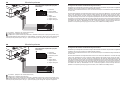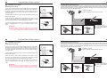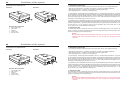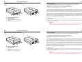
1
TB 1010 Time
KURZANLEITUNG
QUICK USER GUIDE
KRÓTKA INSTRUKCJA
Version 06/2013
60.0835.0-04-170613
TB 1010 Time
KURZANLEITUNG
QUICK USER GUIDE
KRÓTKA INSTRUKCJA
Version 06/2013
60.0835.0-04-170613
Introductory information
3
Sehr geehrte Kundin, sehr geehrter Kunde,
Sie haben ein Produkt der Marke BURY erworben und sich so für ein Produkt mit hoher Qualität sowie
höchstem Bedienkomfort entschieden.
Dear customer,
Congratulation on purchasing a BURY product. You have chosen a high quality product that is extremely
easy to use.
Szanowna Klientko, szanowny Kliencie,
Kupując urządzenie marki BURY zdecydowali się Państwo na produkt wysokiej jakości, cechujący się
komfortową obsługą.
Installation of the system
4
Lieferumfang
Scope of supply
Zawartość
Beschreibung der Komponenten:
1. Telematik-Elektronikbox
2. 3-Tastenfernbedienung
2. Stromversorgungskabel
und Sicherungen
4. Kurzanleitung
5. Montagezubehör
Scope of delivery:
1. Telematic - electronic box
2. 3 key remote control
3. Power supply cable with fuses
4. Quick user guide
5. Mounting accessories
W komplecie:
1. Telematik - centralka elektroniczna
2. Pilot z 3 przyciskami
3. Kabel zasilający z bezpiecznikami
4. Skrócona instrukcja obsługi
5. Akcesoria montażowe
49
Refurbished parts may be used to repair the goods. Upon validation of your warranty claim, PTP will send your
replacement unit, freight paid and include a pre-paid return bag for the return of the faulty product. If you
choose do not wish to proceed with the warranty claim, you must return the replacement unit to us using the
pre-paid return bag. Failure by the customer to return either unit within 14 days may incur a charge for the cost
of the replacement unit.
WARRANTY EXCLUSIONS.
Failure to provide a proof of purchase will result in your warranty claim being rejected.
Product failure due to customer misuse, abuse or abnormal use, failure by the customer to take reasonable care,
failure sure to not using the product in accordance with instructions stated in the manufacturers user guide.
Product failure due to recommended installation procedures not being followed as stated in the manufacturers
guide.
YOUR RIGHTS UNDER THE AUSTRALIAN CONSUMER LAW
Our goods come with guarantees that cannot be excluded under the Australian Consumer Law.
You are entitled to a replacement or refund for a major failure and for compensation for any other reasonable
foreseeable loss or damage. You are entitled to have goods repaired or replaced if the goods fail to be of acceptable quality and the failure does not amount to a major failure.
Montage des Systems
48
EXPRESS WARRANTY AGAINST DEFECTS – AUSTRALIA:
This product if imported by Point to Point Distributions Pty Ltd is warranted in Australia to be free from any
defect in material and workmanship, subject to the following terms and conditions.
Who provides this warranty: Point to Point Distributions Pty Ltd
Unit 9, 7-8 Len Thomas Place Narre Warren Vic, 3805.
Tel: +61 3 8794 1800
Email: [email protected]
Geographical Region:
PRODUCTS PURCHASED IN AUSTRALIA
imported by Point to Point Distributions Pty Ltd.
Warranty Period:
2 YEARS FROM DATE OF PURCHASE
(please retain your receipt as your proof of purchase will be required
to valid warranty claim)
WARRANTY CLAIM PROCESS:
In the unfortunate event of a failure of your product, please contact Point to Point Distributions via our email
address or phone:
Tel: +61 3 8794 1800
EMAIL: [email protected]
PTP will ask you to provide evidence of your purchase receipt, to establish the warranty claim is within the 1 year
warranty period. Failure to provide your purchase receipt will result in PTP rejecting your warranty claim.
PTP offers an advance replacement of your faulty product. Please not our replacement units are
a like-for-like product, and may be refurbished units that are of the exact same model and version. Goods presented for repair may be replaced by refurbished goods of the same type rather than being repaired.
5
Montage des Systems
Positionierung und Befestigung
Die TB 1010 Time Telematikbox ist mit integrierter GSM-Antenne sowie integrierter GPS-Antenne ausgestattet.
Da sich beide Antennen im Gehäuseoberteil befinden achten Sie bitte darauf,
dass die Gehäuseseite mit den Anschlussbeschriftungen nach oben zeigt.
Metallelemente im Armaturenbrett, metallbedampfte Windschutzscheiben
oder die Heizdrähte einer Frontscheibenheizung können den Empfang beeinträchtigen (siehe auch unter Punkt 6).
Das Gerät soll unter dem Armaturenbrett an einer unsichtbaren Stelle oder
in dem Handschuhfach in Fahrtrichtung in der horizontalen Position oder unter einem Winkel von max. 45 Grad platziert werden, um den guten Empfang
des GPS Signals und die optimale Übertragung des GSM Signals zu sichern.
Die Telematikbox sollte auf einer trockenen, sauberen und fettfreien Fläche mit
Klebestreifen befestigt werden. Extreme Temperaturschwankungen und -unterschiede können die Hafteigenschaften der Klebestreifen beeinträchtigen.
Wichtig:
X Installieren Sie die Telematikbox hinter einer Verkleidung, damit diese erst nach Öffnen/Entfernen einer Blende/Abdeckung
sichtbar und zugänglich ist. Die Telematikbox muss vibrationsfrei
fixiert werden.
2b
2a
2a, 2b - siehe Abb. auf Seite 6
Montage des Systems
6
47
Zur Befestigung des Gerätes TB 1010 Time verwenden Sie bitte das beiliegende Klebeband.
Achtung:
X Bitte beachten Sie, dass der Produkt-Aufkleber an der Unterseite der Telematikbox nicht überklebt, zerstört oder entfernt wird.
1
2a
2b
3
Szczegółowe wyjaśnienia dotyczące gwarancji (rękojmia / gwarancja / serwis) w danych krajach można znaleźć
na końcu tej instrukcji.
Wskazówki dotyczące usuwania urządzeń elektrycznych w UE
Symbol przekreślonego kosza na odpady na kołach oznacza, że elektryczne i elektroniczne produkty, baterie
i akumulatory w Unii Europejskiej muszą być zbierane oddzielnie. Proszę nie usuwać takich odpadów poprzez
niesortowane odpady domowe. Jako posiadacz starego urządzenia są Państwo zobowiązani do jego przekazania
do odpowiednich miejsc odbioru lub do komunalnych punktów zbiórki. Stare urządzenia elektryczne są tam
przyjmowane nieodpłatnie.
Certyfikaty i deklaracje zgodności
Produkcja, Zaopatrzenie, Serwis i Zbyt w firmie BURY oparte są na rozwiązaniach organizacyjnych Systemu
Zarządzania Jakością ISO/TS 16949 oraz procesach przyjaznych środowisku zgodnych z ISO 14001. Urządzenie
głośnomówiące spełnia również normy bezpieczeństwa CE:
Certyfikat CE odpowiada wytycznym R&TTE 1999/5/WE.
Deklarację zgodności producenta dla tego systemu można otrzymać drogą mailową pisząc na adres:
ce_conformance@bury. Dostępna jest również na naszej stronie internetowej www.bury.com/go/ce
Zastrzega sie prawo do pomyłek i zmian.
© 2013 by BURY. Wszelkie prawa zastrzeżone.
Pozostałe informacje
46
Anschlussmöglichkeiten der Elektronikbox
Usługi serwisowe
W przypadku ogólnych czy też technicznych pytań, wątpliwości, spostrzeżeń i krytyki prosimy zwrócić się do
naszego zespołu:
Zarząd:
BURY GmbH & Co. KG
Robert-Koch-Straße 1-7
D-32584 Löhne
NIEMCY
7
Vorderseite:
Rückseite:
Producent:
BURY Spółka z o.o.
ul. Wojska Polskiego 4
39-300 Mielec
POLSKA
Infolinia tel.: (17) 584 52 00
Serwis tel.: (17) 773 86 02
(17) 773 87 33
Pon.-pt. 8:00-16:00
E-mail: [email protected]
Gwarancja / Serwisowanie
Gwarancja dla komponentów niniejszego produktu wynosi 2 lata od daty sprzedaży dla klienta ostatecznego.
Roszczenia gwarancyjne należy kierować do Państwa strony umowy. Jeśli strona umowy nie może usunąć wady
należy skorzystać z prawa nabywcy. Jeśli uzgodnią Państwo ze stroną umowy, że produkt będzie przesłany
bezpośrednio do producenta w ramach reklamacji, prosimy o opisanie problemu z produktem i przesłanie kopii
dowodu zakupu bezpośrednio do naszego serwisu:
BURY Sp. z o.o.
ul. Wojska Polskiego 4
39-300 Mielec
POLSKA
Anschlüsse an der Elektronikbox:
1 Statusanzeige (LED)
2 SIM-Karten-Slot
3 USB-Schnittstelle (Softwareupdate)
4 Stromversorgung
5 Fernbedienung für das elektronische Fahrtenbuch
8
Montage des Systems
45
1 - Statusanzeige (LED)
1. Im normalen Betriebsmodus sieht die LED- Statusanzeige auf der Fernbedienung und der Box wie folgt aus:
Specific explanations regarding the assertion of claims based on defects of the product (warranty / guarantee /
service) for certain countries can be found at the end of these instructions.
- die LED-Diode leuchtet einheitlich - die GPS-Signal und die Verbindung mit dem Portal richtig
- die Diode blinkt alle 1 Sek. impulsiv - keine Verbindung mit dem Portal (kein GSM-Signal)
- die Diode blinkt alle 0,5 Sek. impulsiv - kein GPS-Signal
Information on the disposal of electrical goods in the EU
The crossed out wheelie bin symbol means that electrical and electronic products, batteries and accumulators
must be disposed of separately in the European Union. Please do not dispose of any such products in your normal household waste. As the owner of a product of this sort you are legally obliged to dispose of it at your local
dumping site or recycling centre, where you are able to leave your waste electrical goods free of charge.
2. Konfigurationsmodus - kurzes Blinken der LED-BOX Diode alle 2 Sek., schnelles Blinken abwechselnd - Vorbereitung der Aktualisierung der Software (nach der Installation mittels BURY Update Manager). Dann erlischt die
LED und bleibt in diesem Zustand, bis die Aktualisierung abgeschlossen ist. Bis Sie den Konfigurationsmodus
wieder starten (blinkt kurz alle 2 Sekunden), trennen Sie nicht das USB-Kabel vom Gerät. Der Update-Vorgang
im Konfigurationsmodus dauert etwa 2-3 Minuten.
3. Signalisieren des Beginns der automatischen Aktualisierung (nach Senden des Updates via GSM) - Leuchtdioden blinken schnell und abwechselnd der Reihe nach, beginnend von der Diode für Dienstfahrt (DienstfahrtFahrt zur Arbeit-Privatfahrt: grün-gelb-rot). Die Sequenz wird 6 x wiederholt und dauert ca. 3-4 Sek. Danach
beginnt das Gerät den Update-Prozess durchzuführen, der ca. 1-2 Minuten dauern kann. Zu diesem Zeitpunkt ist
es nicht in der Lage, den Normalbetrieb zu realisieren.
Approvals and declaration of conformity
At BURY, purchase, production, as well as distribution and service, follow environmentally friendly processes
according to the ISO 14001 Standard and Quality Management Requirements, according to the ISO/TS 16949
Standard. The BURY CC 9058 has
the CE approval pursuant to the R&TTE 1999/5/EC regulation
You can request a conformity declaration from the manufacturer of this product by by writing to the following email address: [email protected]. It is also available on our web site www.bury.com/go/ce
2 - SIM-Karten Slot
Stecken Sie die SIM-Karte in den SIM-Einschub links am Gehäuse der Elektronikbox ein, bis Sie ein Klick hören
können, was bedeutet, dass die Karte richtig platziert ist. Sie kann mit der Schutzkappe vor unbefugtem Gebrauch geschützt werden.
Wichtig:
X Die Kunststoffkappe mit der Sie die Buchse Ihrer SIM-Karte schliessen, wird bei der Eröffnung
beschädigt. Damit das System stabil arbeiten kann, ziehen Sie die SIM-Karte niemals aus, während Sie das Gerät einschalten.
8
Subject to change. Errors and omissions excepted.
© 2013 by BURY. All rights reserved.
Montage des Systems
45
1 - Statusanzeige (LED)
1. Im normalen Betriebsmodus sieht die LED- Statusanzeige auf der Fernbedienung und der Box wie folgt aus:
Specific explanations regarding the assertion of claims based on defects of the product (warranty / guarantee /
service) for certain countries can be found at the end of these instructions.
- die LED-Diode leuchtet einheitlich - die GPS-Signal und die Verbindung mit dem Portal richtig
- die Diode blinkt alle 1 Sek. impulsiv - keine Verbindung mit dem Portal (kein GSM-Signal)
- die Diode blinkt alle 0,5 Sek. impulsiv - kein GPS-Signal
Information on the disposal of electrical goods in the EU
The crossed out wheelie bin symbol means that electrical and electronic products, batteries and accumulators
must be disposed of separately in the European Union. Please do not dispose of any such products in your normal household waste. As the owner of a product of this sort you are legally obliged to dispose of it at your local
dumping site or recycling centre, where you are able to leave your waste electrical goods free of charge.
2. Konfigurationsmodus - kurzes Blinken der LED-BOX Diode alle 2 Sek., schnelles Blinken abwechselnd - Vorbereitung der Aktualisierung der Software (nach der Installation mittels BURY Update Manager). Dann erlischt die
LED und bleibt in diesem Zustand, bis die Aktualisierung abgeschlossen ist. Bis Sie den Konfigurationsmodus
wieder starten (blinkt kurz alle 2 Sekunden), trennen Sie nicht das USB-Kabel vom Gerät. Der Update-Vorgang
im Konfigurationsmodus dauert etwa 2-3 Minuten.
3. Signalisieren des Beginns der automatischen Aktualisierung (nach Senden des Updates via GSM) - Leuchtdioden blinken schnell und abwechselnd der Reihe nach, beginnend von der Diode für Dienstfahrt (DienstfahrtFahrt zur Arbeit-Privatfahrt: grün-gelb-rot). Die Sequenz wird 6 x wiederholt und dauert ca. 3-4 Sek. Danach
beginnt das Gerät den Update-Prozess durchzuführen, der ca. 1-2 Minuten dauern kann. Zu diesem Zeitpunkt ist
es nicht in der Lage, den Normalbetrieb zu realisieren.
Approvals and declaration of conformity
At BURY, purchase, production, as well as distribution and service, follow environmentally friendly processes
according to the ISO 14001 Standard and Quality Management Requirements, according to the ISO/TS 16949
Standard. The BURY CC 9058 has
the CE approval pursuant to the R&TTE 1999/5/EC regulation
You can request a conformity declaration from the manufacturer of this product by by writing to the following email address: [email protected]. It is also available on our web site www.bury.com/go/ce
2 - SIM-Karten Slot
Stecken Sie die SIM-Karte in den SIM-Einschub links am Gehäuse der Elektronikbox ein, bis Sie ein Klick hören
können, was bedeutet, dass die Karte richtig platziert ist. Sie kann mit der Schutzkappe vor unbefugtem Gebrauch geschützt werden.
Wichtig:
X Die Kunststoffkappe mit der Sie die Buchse Ihrer SIM-Karte schliessen, wird bei der Eröffnung
beschädigt. Damit das System stabil arbeiten kann, ziehen Sie die SIM-Karte niemals aus, während Sie das Gerät einschalten.
Subject to change. Errors and omissions excepted.
© 2013 by BURY. All rights reserved.
Further Information
44
Service
In case of general or technical queries, suggestions and comments, please do not hesitate to contact our team
at any time. Suggestions and feedback are always welcomed:
Administration:
BURY GmbH & Co. KG
Robert-Koch-Straße 1-7
D-32584 Löhne
GERMANY
Producer:
BURY Spółka z o.o.
ul. Wojska Polskiego 4
39-300 Mielec
POLAND
Hotline:
+49(0)180 5 - 842 468*
Faxline:
+49(0)180 5 - 842 329*
* 0.14 €/min. Deutsche Telekom AG landline the costs of international telephone calls which are made from
abroad can vary.
E-Mail:
[email protected]
9
3 - USB-Schnittstelle (Softwareupdate)
Verbindung mit PC, mittels beiliegendem USB-Kabel, zur Konfiguration der Telematikbox oder zur Aktualisierung
deren Software.
4 - Stromversorgung
Die Telematikbox wird über das 7-adrige Molex-Kabel an die Stromversorgung angeschlossen. Schließen Sie das
schwarze (Klemme 31 - Minus), das rote (Klemme 30 - Dauerplus) und das blaue Kabel (Klemme 15 - Zündungsplus) an die Konstantstromquelle.
Achtung:
X Das blaue Kabel darf nicht an Klemme 30 angeschlossen
werden. Ansonsten kann keine Fahrt abgeschlossen oder gestartet werden (Bedarf des Zündungssignals) und bei längerem
Stillstand des Fahrzeugs könnte es zudem zur Entladung der
Autobatterie führen.
Warranty / Service desk:
The duration of the warranty for the components of this product totals two years subsequent to the date of sale
to the end customer. Any warranty claims you may have as an end customer are to be asserted towards your
contractual partner. If the corresponding contractual partner is not able to rectify a corresponding fault, please
exercise your rights of purchase. If subsequent to agreement with your contractual partner the product is to be
sent directly to the manufacturer, then please send it, along with a detailed description of the fault in the German
or English language and a copy of the proof of purchase, directly to our service team:
BURY GmbH & Co. KG
Im Hause DPD Depot 103
Robinienweg
D-03222 Lübbenau
GERMANY
Further Information
44
Service
In case of general or technical queries, suggestions and comments, please do not hesitate to contact our team
at any time. Suggestions and feedback are always welcomed:
Administration:
BURY GmbH & Co. KG
Robert-Koch-Straße 1-7
D-32584 Löhne
GERMANY
Producer:
BURY Spółka z o.o.
ul. Wojska Polskiego 4
39-300 Mielec
POLAND
Hotline:
+49(0)180 5 - 842 468*
Faxline:
+49(0)180 5 - 842 329*
* 0.14 €/min. Deutsche Telekom AG landline the costs of international telephone calls which are made from
abroad can vary.
E-Mail:
[email protected]
Warranty / Service desk:
The duration of the warranty for the components of this product totals two years subsequent to the date of sale
to the end customer. Any warranty claims you may have as an end customer are to be asserted towards your
contractual partner. If the corresponding contractual partner is not able to rectify a corresponding fault, please
exercise your rights of purchase. If subsequent to agreement with your contractual partner the product is to be
sent directly to the manufacturer, then please send it, along with a detailed description of the fault in the German
or English language and a copy of the proof of purchase, directly to our service team:
BURY GmbH & Co. KG
Im Hause DPD Depot 103
Robinienweg
D-03222 Lübbenau
GERMANY
9
3 - USB-Schnittstelle (Softwareupdate)
Verbindung mit PC, mittels beiliegendem USB-Kabel, zur Konfiguration der Telematikbox oder zur Aktualisierung
deren Software.
4 - Stromversorgung
Die Telematikbox wird über das 7-adrige Molex-Kabel an die Stromversorgung angeschlossen. Schließen Sie das
schwarze (Klemme 31 - Minus), das rote (Klemme 30 - Dauerplus) und das blaue Kabel (Klemme 15 - Zündungsplus) an die Konstantstromquelle.
Achtung:
X Das blaue Kabel darf nicht an Klemme 30 angeschlossen
werden. Ansonsten kann keine Fahrt abgeschlossen oder gestartet werden (Bedarf des Zündungssignals) und bei längerem
Stillstand des Fahrzeugs könnte es zudem zur Entladung der
Autobatterie führen.
10
Montage des Systems
43
Installation der Sicherungen (siehe Abbildung)
Durchtrennen Sie bitte mit einem Seitenschneider oder einer Schere das rote und blaue Kabel. Legen Sie nun
die beiden Enden des roten Kabels, die sich durch den Schnitt ergeben, in einen der Klemmverbinder ein. Klappen Sie diesen nun zu. Hören Sie zweimal ein Knacken, ist die Klemme korrekt eingerastet. Setzen Sie nun eine
der Sicherungen ein und wiederholen Sie dann den Vorgang für das andere Kabel.
- Installation auf dem Kabel:
Zündung (blau) und Spannungsquelle (rot)
BURY GmbH & Co. KG
Im Hause DPD Depot 103
Robinienweg
D-03222 Lübbenau
Deutschland
Außerdem geben wir auf alle Komponenten zwei Jahre Gewährleistung. Spezifische Erklärungen zur Geltungmachung von Mängelansprüchen (Gewährleistung / Garantie / Service) für bestimmte Länder finden Sie am Ende
der Anleitung.
Hinweise zur Entsorgung von Elektrogeräten in der EU
Das Symbol der durchgestrichenen Abfalltonne auf Rädern bedeutet, dass elektrische und elektronische Produkte, Batterien und Akkumulatoren in der Europäischen Union einer getrennten Müllsammlung zugeführt werden
müssen. Entsorgen Sie diese Produkte nicht über den unsortierten Hausmüll. Als Besitzer eines Altgerätes sind
Sie verpflichtet, dieses zu den vorgesehenen Annahme- oder kommunalen Sammelstellen zu bringen. Elektroaltgeräte werden dort kostenlos angenommen.
- Erdung (schwarz)
- 12/24V Zündung (blau)
- 12/24V Spannungsquelle
(rot)
Zulassungen und Konformitätserklärungen
Produktion, Einkauf, Service und Vertrieb sind auf die Organisationslösungen des Qualitätsmanagements nach
ISO/TS 16949 und die umweltfreundlichen Prozesse nach ISO 14001 gestützt. Die FSE besitzt die
CE Zulassung entsprechend der Richtlinie R&TTE 1999/5/EG
Eine Konformitätserklärung des Herstellers für dieses System können Sie postalisch unter folgender E-Mail Adresse anfordern: [email protected]. Sie ist auch auf unserer Webseite www.bury.com/go/ce zu finden.
Irrtum und Änderungen vorbehalten
© 2013 by BURY. Alle Rechte vorbehalten.
Weitere Informationen
42
Service
11
Anschlussplan für den Kabelbaum (8-Pin Molexstecker)
Bei allgemeinen oder technischen Fragen, Anregungen und Kritiken steht Ihnen unser Team zu jeder Zeit zur
Verfügung. Wir sind für Ihre Vorschläge und Bemerkungen offen:
Verwaltung:
BURY GmbH & Co. KG
Robert-Koch-Straße 1-7
D-32584 Löhne
Deutschland
Produzent:
BURY Spółka z o.o.
ul. Wojska Polskiego 4
39-300 MIELEC
Polen
Hotline:
+49(0)180 5 - 842 468*
Faxline:
+49(0)180 5 - 842 329*
* 0,14 €/Min. aus dem Festnetz der Deutschen Telekom AG, deutscher Mobilfunk max. 0,42 €/Min.
Die Kosten für Anrufe aus dem internationalem Ausland können abweichen.
E-Mail:
[email protected]
Gewährleistung / Serviceannahme
Die Gewährleistungsdauer für die erworbenen Komponenten dieses Produktes beträgt zwei Jahre ab Verkaufsdatum an den Endkunden. Gewährleistungsansprüche für Sie als Endkunde bestehen gegenüber Ihrem Vertragspartner. Sollte der jeweilige Vertragspartner einen vorhandenen Mangel nicht beseitigen können, nehmen
Sie bitte Ihre Käuferrechte in Anspruch. Soll nach Absprache mit Ihrem Vertragspartner das Produkt aus Reklamationsgründen direkt zum Hersteller geschickt werden, dann senden Sie dieses mit ausführlicher Fehlerbeschreibung und einer Kopie des Kaufbelegs in deutscher oder englischer Sprache direkt an unser Serviceteam:
1
2
3
4
5
6
7
8
-
Erdung
Spannungsquelle
Digital-Gnd
Zündung
Alarm-In
Digital-In
Analog-In
- 8 Pin Molexstecker - Anschluss an die Elektronikbox
- Anschluss ans Bordnetz
- Anschluss an die Autoalarmanlage. Möglich wird es ein automatisches Einloggen bei jeglicher Aktivierung
des Systems, z. B. bei einem Autodiebstahlversuch. Das Einloggen erfolgt ständig bis der Zündschlüssel gedreht
wird - voller Zyklus, d.h. ein-und ausschalten.
12
Montage des Systems
- Anschluss an die digitale Erdung mit einem digitalen Eingang
- Anschluss Digitaler Schalt-Eingang des Fahrzeugs (Türkontakt) oder einer Sensorik
- Anschluss Analoger Schalt-Eingang vom Fahrzeug oder Sensorik
Spezifikation der Systemvoraussetzungen
Betriebsspannung: min.: 9 V – max.: 31 V (typisch 12/24)
Ruhestromaufnahme: < 1 mA
Arbeitsspannung: PKW < 500 mA, LKW < 400 mA (Spitzenwert etwa 1 A)
Frequenzbänder: Quad Band – GSM 850, GSM 900, DCS 1800, PCS 1900
SIM-Schnittstelle (Kartenleser): 3 V, 1,8 V
Temperaturbereich: -20ºC bis +70º C
Digital-IN (Digitaleingang): Eingang für digitale Signale – min.: 12 V: 3 V / 24 V: 9 V, typisch: - ; max. 36 V
Alarm-IN (Alarmeingang): Eingang für Alarmsignale – min.: 12 V: 9 V / 24 V: 9 V, typisch: -; max. 36 V
Analog-IN (Analogeingang): Eingang für analoge Signale – min. 0 V; typisch: - ; max. 36 V
U12V/24V über 3 A abgesichert
Zündung über 3 A abgesichert
GPS-Antenne (Antennentyp): Dielektrische Patch- Antenne
GPS-Modul: MTK Chipset
USB-Port: Mini-USB 2.0
41
Użycie przycisków:
a) pojedyncze krótkie wciśnięcie przycisku powoduje zakończenie poprzednio realizowanej, i rozpoczęcie nowej
trasy typu zgodnego z naciśniętym przyciskiem, chyba że jest naciskany przycisk oznaczający ten sam typ trasy
(naciskanie już podświetlanego przycisku).
b) naciśnięcie i przytrzymanie przez ok. 3 s przycisku powoduje ustawienie domyślnego typu trasy, który jest
wybierany zawsze po dłuższym postoju pojazdu i zostanie zasygnalizowane trzykrotnym szybkim migającym
podświetleniem wszystkich trzech przycisków jednocześnie.
c) jednoczesne krótkie naciśnięcie przycisków środkowego i lewego lub prawego powoduje zmniejszenie lub
zwiększenie jasności podświetlenia pilota (przełączenie trybu dziennego na tryb nocny).
W sytuacji, kiedy podświetlenie jest nieaktywne, urządzenie nie pracuje, jest w trybie konfiguracyjnym bądź
w trybie aktualizacji.
Konfiguracja urządzenia i aktualizacja oprogramowania
Update i konfiguracja urządzenia będzie możliwa za pomocą kabla USB i odpowiedniej aplikacji PC.
Na komputerze należy zainstalować oprogramowanie dostarczane z urządzeniem. Prosimy podłączyć kabel USB
do TB 1010 Time oraz do Państwa komputera. Gniazdo USB znajduje się na obudowie TB 1010 Time.
Po uruchomieniu w trybie konfiguracji dioda led urządzenia miga krótko co ok. 2 s. Po skopiowaniu oprogramowania dioda zaczyna szybko migać, sygnalizując proces przygotowania do aktualizacji oprogramowania, po czym
urządzenie przejdzie do właściwego procesu aktualizacji, podczas którego nie należy odłączać urządzenia od
źródła zasilania (USB). Po zakończeniu procesu aktualizacji, urządzenie powinno wrócić do trybu konfiguracji, co
będzie ponownie sygnalizowane przez krótkie mignięcia diody co ok. 2 s. Odłączenie urządzenia od zasilania
podczas aktualizacji może doprowadzić do jego uszkodzenia!
40
Instrukcja obsługi
Ważne:
X Wiele niemieckich urzędów finansowych wykorzystuje tego rodzaju elektroniczną ewidencję przebiegu pojazdu jako dowód przy rozliczaniu skarbowym podatnika. Firma BURY GmbH&Co.KG deklaruje
niniejszym, że nie ma obowiązku dostarczenia (polepszenia, czy też zmiany) niniejszego lub innego
oprogramowania urzędowi skarbowemu w Niemczech lub innych krajach, w przypadku, gdy użytkownik
tego oprogramowania rozlicza się przed urzędem skarbowym.
X Aczkolwiek mogą Państwo zwrócić się do nas w przypadku problemów z urzędami finansowymi.
13
Verbinden Sie den 8-poligen Molexstecker (A) mit der Telematikbox (siehe Abbildung)
Można wybrać trzy różne typy podróży, naciskając odpowiedni przycisk na pilocie. Wybrany tryb zostanie zasygnalizowany podświetleniem przycisku.
(symbol czerwony):
Podróż prywatna
Dotyczy prywatnych podróży, które nie mają charakteru służbowego.
(symbol zielony):
Podróż służbowa
Dotyczy służbowych podróży, które nie mają charakteru prywatnego.
5 - Fernbedienung mit Kabel
(symbol żółty):
Podróż do pracy i z pracy
Dotyczy podróży do pracy. Powrót z pracy będzie mieć charakter podróży prywatnej, gdyż tak jest traktowany
przez niemieckiego ustawodawcę. W innych krajach może być traktowany inaczej.
Po zatrzymaniu pracy silnika urządzenie zapamiętuje ostatnio wybrany rodzaj podróży.
40
Instrukcja obsługi
Ważne:
X Wiele niemieckich urzędów finansowych wykorzystuje tego rodzaju elektroniczną ewidencję przebiegu pojazdu jako dowód przy rozliczaniu skarbowym podatnika. Firma BURY GmbH&Co.KG deklaruje
niniejszym, że nie ma obowiązku dostarczenia (polepszenia, czy też zmiany) niniejszego lub innego
oprogramowania urzędowi skarbowemu w Niemczech lub innych krajach, w przypadku, gdy użytkownik
tego oprogramowania rozlicza się przed urzędem skarbowym.
X Aczkolwiek mogą Państwo zwrócić się do nas w przypadku problemów z urzędami finansowymi.
13
Verbinden Sie den 8-poligen Molexstecker (A) mit der Telematikbox (siehe Abbildung)
Można wybrać trzy różne typy podróży, naciskając odpowiedni przycisk na pilocie. Wybrany tryb zostanie zasygnalizowany podświetleniem przycisku.
(symbol czerwony):
Podróż prywatna
Dotyczy prywatnych podróży, które nie mają charakteru służbowego.
(symbol zielony):
Podróż służbowa
Dotyczy służbowych podróży, które nie mają charakteru prywatnego.
(symbol żółty):
Podróż do pracy i z pracy
Dotyczy podróży do pracy. Powrót z pracy będzie mieć charakter podróży prywatnej, gdyż tak jest traktowany
przez niemieckiego ustawodawcę. W innych krajach może być traktowany inaczej.
Po zatrzymaniu pracy silnika urządzenie zapamiętuje ostatnio wybrany rodzaj podróży.
5 - Fernbedienung mit Kabel
Bedienungsanleitung
Instrukcja obsługi
Funktionen des TB 1010 Time
1. Positionsermittlung und Fahrzeugverfolgung:
Sobald die Zündung des Fahrzeugs gestartet wird, ist die TB 1010 Time Telematikbox aktiv. Eine Statusmeldung
folgt an das Webportal und fortlaufend werden nun die GPS-Koordinaten des fahrenden Fahrzeugs erfasst. Die
Streckendaten werden mit einem jeweiligen Zeitstempel gespeichert und per GPRS an das Online-Webportal
übermittelt. Im Internet, über den „BURY Fleetmanager“ (das Online-Portal), kann der Streckenverlauf des
Fahrzeugs in einer Digitalen-Karte in Echtzeit nachverfolgt werden. Sobald die Zündung des Fahrzeugs abgeschaltet wird, wird dieses Ereignis ebenfalls gespeichert und es folgt wieder eine Statusmeldung an das Webportal. Sollten die zusätzlichen Eingänge (digital/analog) geschaltet werden, generiert dieses Ereignis ebenfalls eine
Statusmeldung an das Webportal.
Funkcje TB 1010 Time
1. Określanie pozycji i śledzenie pojazdu:
Jeśli zapłon pojazdu zostanie włączony, boks Telematik zostanie aktywowany. Do portalu internetowego dotrze
informacja o statusie i współrzędne GPS jadącego pojazdu będą na bieżąco rejestrowane.
Dane trasy będą zapisywane z pewnym odstępem czasowym i przekazywane do portalu internetowego online
za pomocą GPRS. W internecie, za pomocą „BURY Fleetmanager” (portal online) można śledzić przebieg trasy
pojazdu na cyfrowej mapie w czasie rzeczywistym.
Jeśli zapłon pojazdu zostanie wyłączony, to zdarzenie zostanie zarejestrowane w pamięci i do portalu internetowego dotrze znów informacja o statusie.
Jeśli zostaną podłączone dodatkowe wejścia (cyfrowe/analogowe), to znów zostanie wygenerowana informacja
o statusie.
14
Sollte das Gerät keinen GSM-Empfang haben weil sich das Fahrzeug ausserhalb des authorisierten Mobilfunknetzes befindet, werden die Daten zwischengespeichert. Folgende Daten werden gespeichert:
- Datum und Zeit
- Fahrzeugposition
- Geschwindigkeit
- Höhe über Meerespiegel
- die Anzahl der georteten Satelliten.
39
Jeśli urządzenie nie będzie odbierać sygnałów GSM, ponieważ pojazd będzie znajdować się poza zasięgiem autoryzowanej sieci komórkowej, dane będą zapisywane w pamięci buforowej. Następujące dane są zapisywane:
- data i czas
- pozycja pojazdu
- prędkość
- wysokość nad poziomem morza
- liczba wykrytych satelit
2. Elektronisches Fahrtenbuch
Die aufgezeichneten Streckendaten der TB 1010 Time Telematikbox generieren zusätzlich ein Fahrtenbuch. Über
die 3-Tasten Fernbedienung geben Sie den jeweiligen Fahrtmodus ein: Dienstfahrt, Pendlerfahrt und Privatfahrt.
Diese werden automatisch zusammen mit den Streckendaten gespeichert und ebenfalls. per GPRS an das WebPortal übermittelt.
Das Fahrtenbuch kann jederzeit Online mit den notwendigen Daten: Anschrift, Zweck der Reise und Gesprächspartner ergänzt und als Datei für das Finanzamt ausgedruckt werden.
2. Elektroniczna książka pojazdu
Zapisane dane trasy boksu Telematik TB 1010 Time generują dodatkowo książkę pojazdu. Za pomocą 3-klawiszowego pilota należy wprowadzić tryb podróży: podróż służbowa, do pracy i z pracy i prywatna. Zostaną one
automatycznie razem z danymi trasy zarejestrowane w pamięci i również za pomocą GPRS przekazane do portalu internetowego. Książka pojazdu może być w każdym momencie uzupełniona online o potrzebne dane (adres,
cel podróży i rozmówca) i wydrukowana.
Bedienungsanleitung
Instrukcja obsługi
Funktionen des TB 1010 Time
1. Positionsermittlung und Fahrzeugverfolgung:
Sobald die Zündung des Fahrzeugs gestartet wird, ist die TB 1010 Time Telematikbox aktiv. Eine Statusmeldung
folgt an das Webportal und fortlaufend werden nun die GPS-Koordinaten des fahrenden Fahrzeugs erfasst. Die
Streckendaten werden mit einem jeweiligen Zeitstempel gespeichert und per GPRS an das Online-Webportal
übermittelt. Im Internet, über den „BURY Fleetmanager“ (das Online-Portal), kann der Streckenverlauf des
Fahrzeugs in einer Digitalen-Karte in Echtzeit nachverfolgt werden. Sobald die Zündung des Fahrzeugs abgeschaltet wird, wird dieses Ereignis ebenfalls gespeichert und es folgt wieder eine Statusmeldung an das Webportal. Sollten die zusätzlichen Eingänge (digital/analog) geschaltet werden, generiert dieses Ereignis ebenfalls eine
Statusmeldung an das Webportal.
Funkcje TB 1010 Time
1. Określanie pozycji i śledzenie pojazdu:
Jeśli zapłon pojazdu zostanie włączony, boks Telematik zostanie aktywowany. Do portalu internetowego dotrze
informacja o statusie i współrzędne GPS jadącego pojazdu będą na bieżąco rejestrowane.
Dane trasy będą zapisywane z pewnym odstępem czasowym i przekazywane do portalu internetowego online
za pomocą GPRS. W internecie, za pomocą „BURY Fleetmanager” (portal online) można śledzić przebieg trasy
pojazdu na cyfrowej mapie w czasie rzeczywistym.
Jeśli zapłon pojazdu zostanie wyłączony, to zdarzenie zostanie zarejestrowane w pamięci i do portalu internetowego dotrze znów informacja o statusie.
Jeśli zostaną podłączone dodatkowe wejścia (cyfrowe/analogowe), to znów zostanie wygenerowana informacja
o statusie.
14
Sollte das Gerät keinen GSM-Empfang haben weil sich das Fahrzeug ausserhalb des authorisierten Mobilfunknetzes befindet, werden die Daten zwischengespeichert. Folgende Daten werden gespeichert:
- Datum und Zeit
- Fahrzeugposition
- Geschwindigkeit
- Höhe über Meerespiegel
- die Anzahl der georteten Satelliten.
2. Elektronisches Fahrtenbuch
Die aufgezeichneten Streckendaten der TB 1010 Time Telematikbox generieren zusätzlich ein Fahrtenbuch. Über
die 3-Tasten Fernbedienung geben Sie den jeweiligen Fahrtmodus ein: Dienstfahrt, Pendlerfahrt und Privatfahrt.
Diese werden automatisch zusammen mit den Streckendaten gespeichert und ebenfalls. per GPRS an das WebPortal übermittelt.
Das Fahrtenbuch kann jederzeit Online mit den notwendigen Daten: Anschrift, Zweck der Reise und Gesprächspartner ergänzt und als Datei für das Finanzamt ausgedruckt werden.
39
Jeśli urządzenie nie będzie odbierać sygnałów GSM, ponieważ pojazd będzie znajdować się poza zasięgiem autoryzowanej sieci komórkowej, dane będą zapisywane w pamięci buforowej. Następujące dane są zapisywane:
- data i czas
- pozycja pojazdu
- prędkość
- wysokość nad poziomem morza
- liczba wykrytych satelit
2. Elektroniczna książka pojazdu
Zapisane dane trasy boksu Telematik TB 1010 Time generują dodatkowo książkę pojazdu. Za pomocą 3-klawiszowego pilota należy wprowadzić tryb podróży: podróż służbowa, do pracy i z pracy i prywatna. Zostaną one
automatycznie razem z danymi trasy zarejestrowane w pamięci i również za pomocą GPRS przekazane do portalu internetowego. Książka pojazdu może być w każdym momencie uzupełniona online o potrzebne dane (adres,
cel podróży i rozmówca) i wydrukowana.
38
Montaż systemu
Proszę podłączyć 8 pinową wtyczkę typu Molex (A) do boksu Telematik (patrz rysunek).
15
Wichtig:
X Viele deutsche Finanzämter erkennen dieses elektronische Fahrtenbuch als Nachweis der beruflichen Mobilität an. Sollte es dennoch im innerdeutschen sowie internationalen Rechtsraum zu
Problemen mit der Anerkennung kommen, übernimmt die Firma BURY GmbH & Co. KG keinerlei
Pflichten zur Bereitstellung, Nachbesserung oder Anpassung der jeweiligen mitgelieferten Software oder einer anderen, insoweit Sie als Nutzer deren Daten zur Abrechnung / als Beweis Ihrer
beruflichen Tätigkeit bei einer Steuerbehörde vorlegen.
X Obgleich dessen sind wir bereit, Ihre Probleme mit den Finanzbehörden diesbezüglich aufzunehmen. Nehmen Sie mit uns Kontakt auf.
Für das Fahrtenbuch können Sie drei unterschiedliche Typen an Fahrten auswählen, während Sie auf die entsprechende Fernbedienungtaste drücken. Der ausgewählte Modus wird durch Beleuchtung der Taste sygnalisiert.
5 - Pilot z kablem
Pozwala wybrać lub zmienić rodzaj podróży.
Privatfahrt
(rotes Symbol):
Grundsätzlich reine private Fahrten, die keinen beruflichen Aspekt besitzen.
Dienstfahrt
(symbol zielony):
Grundsätzlich reine berufliche Fahrten, die keinen privaten Aspekt besitzen.
Pendlerfahrt:
(gelbes Symbol):
Einfache Fahrt zur Arbeitsstätte. Der Rückweg kann als private Fahrt laufen, da dies z. B. vom deutschen Gesetzgeber nicht berücksichtigt wird. Gesetzgebungen in anderen Ländern können abweichen.
Schalten Sie den Motor aus, speichert das Gerät die zuletzt gewählte Fahrt.
16
Bedienungsanleitung
Verwenden von Tasten:
a) einziges kurzes Drücken der Taste verursacht Beenden der aktuellen Fahrt und Anfang neuer Fahrt, die mit
der gedrückten Taste übereinstimmt, es sei denn, eine Taste gedrückt wird, die den gleichen Typ der Fahrt (Drücken, wenn die Taste beleuchtet ist).
b) durch Drücken und Halten der Taste für etwa 3 Sek. wird eine Standdardfahrt gestellt, die nach einem längeren Stillstand des Fahrzeugs gewählt wird. Die Auswahl wird durch ein dreimaliges Blinken signalisiert, wodurch
alle drei Tasten gleichzeitig beleuchtet werden.
c) wenn Sie die Helligkeit der Beleuchtung mindern oder erhöhen möchten, so drücken Sie gleichzeitig auf die
rechte und mittlere oder die linke und mittlere Taste. (Umschalten von Tagmodus auf Nachtmodus).
Wenn die Beleuchtung nicht aktiv ist, arbeitet das Gerät nicht, befindet sich im Konfigurationsmodus oder im
Updatemodus.
16
37
- podłączenie uziemienia cyfrowego wraz z wejściem cyfrowym
- podłączenie wejścia cyfrowego pojazdu (drzwi) lub czujników
- podłączenie do wejścia analogowego pojazdu lub czujników
Specyfikacja wymagań systemowych
Napięcie robocze: min.: 9 V – maks.: 31 V (typowo 12/24)
Prąd spoczynkowy: < 1 mA
Prąd nominalny: samochód < 500 mA, ciężarówka < 400 mA (około 1 A w szczycie)
Pasma częstotliwości: Quadband (cztery pasma) – GSM 850, GSM 900, DCS 1800, PCS 1900
Interfejs SIM (czytnik karty): 3 V; 1,8 V
Zakres temperatury: -20ºC do +70ºC
Wejście cyfrowe: Wejście dla sygnałów cyfrowych – min.: 12 V: 3 V / 24 V: 9 V, typowo: - ; maks. 36 V
Wejście alarmowe: Wejście dla sygnałów alarmowych – min.: 12 V: 9 V / 24 V: 9 V, typowo: -; maks. 36 V
Wejście analogowe: Wejście dla sygnałów analogowych – min. 0 V; typowo: - ; maks. 36 V
U12 V/24 V: 3 A – zabezpieczone
Zapłon: 3 A – zabezpieczony
Antena GPS: Typ – Dielektryczna antena płaska
Moduł GPS: Chipset MTK
Port USB: Mini-USB 2.0
Bedienungsanleitung
Verwenden von Tasten:
a) einziges kurzes Drücken der Taste verursacht Beenden der aktuellen Fahrt und Anfang neuer Fahrt, die mit
der gedrückten Taste übereinstimmt, es sei denn, eine Taste gedrückt wird, die den gleichen Typ der Fahrt (Drücken, wenn die Taste beleuchtet ist).
b) durch Drücken und Halten der Taste für etwa 3 Sek. wird eine Standdardfahrt gestellt, die nach einem längeren Stillstand des Fahrzeugs gewählt wird. Die Auswahl wird durch ein dreimaliges Blinken signalisiert, wodurch
alle drei Tasten gleichzeitig beleuchtet werden.
c) wenn Sie die Helligkeit der Beleuchtung mindern oder erhöhen möchten, so drücken Sie gleichzeitig auf die
rechte und mittlere oder die linke und mittlere Taste. (Umschalten von Tagmodus auf Nachtmodus).
Wenn die Beleuchtung nicht aktiv ist, arbeitet das Gerät nicht, befindet sich im Konfigurationsmodus oder im
Updatemodus.
37
- podłączenie uziemienia cyfrowego wraz z wejściem cyfrowym
- podłączenie wejścia cyfrowego pojazdu (drzwi) lub czujników
- podłączenie do wejścia analogowego pojazdu lub czujników
Specyfikacja wymagań systemowych
Napięcie robocze: min.: 9 V – maks.: 31 V (typowo 12/24)
Prąd spoczynkowy: < 1 mA
Prąd nominalny: samochód < 500 mA, ciężarówka < 400 mA (około 1 A w szczycie)
Pasma częstotliwości: Quadband (cztery pasma) – GSM 850, GSM 900, DCS 1800, PCS 1900
Interfejs SIM (czytnik karty): 3 V; 1,8 V
Zakres temperatury: -20ºC do +70ºC
Wejście cyfrowe: Wejście dla sygnałów cyfrowych – min.: 12 V: 3 V / 24 V: 9 V, typowo: - ; maks. 36 V
Wejście alarmowe: Wejście dla sygnałów alarmowych – min.: 12 V: 9 V / 24 V: 9 V, typowo: -; maks. 36 V
Wejście analogowe: Wejście dla sygnałów analogowych – min. 0 V; typowo: - ; maks. 36 V
U12 V/24 V: 3 A – zabezpieczone
Zapłon: 3 A – zabezpieczony
Antena GPS: Typ – Dielektryczna antena płaska
Moduł GPS: Chipset MTK
Port USB: Mini-USB 2.0
36
Montaż systemu
17
Plan podłączenia wiązki kabla (wtyczka
Molex 8 pin)
1
2
3
4
5
6
7
8
-
Uziemienie
Źródło zasilania
Uziemienie cyfrowe
Zapłon
Wejście alarmu
Wejście cyfrowe
Wejście analogowe
Konfiguration des Gerätes und Aktualisierung der Software:
Aktualisierung und Konfiguration des Gerätes erfolgt via das USB-Kabel und mittels entsprechender PC Applikation.
Installieren Sie auf Ihrem Computer dem Gerät beiligende Software.
Schliessen Sie das USB Kabel mit dem TB 1010 Time und Ihrem Computer. Die USB Buchse liegt am Gehäuse der
TB 1010 Time.
Nach der Inbetriebnahme im Konfigurationsmodus kommt es zu einem kurzen Blinken der Led Diode der Anlage,
was in einem Zeitabstand von etwa 2 Sekunden erfolgt. Nachdem die Software kopiert worden ist, fängt die
Diode an schnell zu blinken, womit der Prozess der Vorbereitung für das Software Update signalisiert wird. Danach geht die Anlage in den Zustand des eigentlichen Updateprozesses über. Hierbei ist darauf zu achten, dass
die Anlage von der Quelle der Spannungsversorgung (USB) nicht getrennt werden soll. Nach dem Abschluss des
Updateprozesses soll die Anlage in den Konfigurationsmodus zurückkommen. Das wird dann auch durch das
kurze Blinken der Diode (in Zeitabständen von etw. 2 Sekunden) signalisiert. Sollte die Anlage während des
Updates von der Spannungsversorgung getrennt werden, kann sie dadurch beschädigt werden!
- 8 pin Molex - podłączenie do centralki elektronicznej
- podłączenie do zasilania samochodowego
- podłączenie do systemu alarmowego samochodu. Umożliwia automatyczne rozpoczęcie logowania w przypadku jakiejkolwiek aktywacji autoalarmu np. próba kradzieży. Logowanie to odbywa się w trybie ciągłym aż do
momentu przekręcenia kluczyka w stacyjce - wykonanie pełnego cyklu stacyjki tzn. włączenie i wyłączenie.
36
Montaż systemu
17
Plan podłączenia wiązki kabla (wtyczka
Molex 8 pin)
1
2
3
4
5
6
7
8
-
Uziemienie
Źródło zasilania
Uziemienie cyfrowe
Zapłon
Wejście alarmu
Wejście cyfrowe
Wejście analogowe
- 8 pin Molex - podłączenie do centralki elektronicznej
- podłączenie do zasilania samochodowego
- podłączenie do systemu alarmowego samochodu. Umożliwia automatyczne rozpoczęcie logowania w przypadku jakiejkolwiek aktywacji autoalarmu np. próba kradzieży. Logowanie to odbywa się w trybie ciągłym aż do
momentu przekręcenia kluczyka w stacyjce - wykonanie pełnego cyklu stacyjki tzn. włączenie i wyłączenie.
Konfiguration des Gerätes und Aktualisierung der Software:
Aktualisierung und Konfiguration des Gerätes erfolgt via das USB-Kabel und mittels entsprechender PC Applikation.
Installieren Sie auf Ihrem Computer dem Gerät beiligende Software.
Schliessen Sie das USB Kabel mit dem TB 1010 Time und Ihrem Computer. Die USB Buchse liegt am Gehäuse der
TB 1010 Time.
Nach der Inbetriebnahme im Konfigurationsmodus kommt es zu einem kurzen Blinken der Led Diode der Anlage,
was in einem Zeitabstand von etwa 2 Sekunden erfolgt. Nachdem die Software kopiert worden ist, fängt die
Diode an schnell zu blinken, womit der Prozess der Vorbereitung für das Software Update signalisiert wird. Danach geht die Anlage in den Zustand des eigentlichen Updateprozesses über. Hierbei ist darauf zu achten, dass
die Anlage von der Quelle der Spannungsversorgung (USB) nicht getrennt werden soll. Nach dem Abschluss des
Updateprozesses soll die Anlage in den Konfigurationsmodus zurückkommen. Das wird dann auch durch das
kurze Blinken der Diode (in Zeitabständen von etw. 2 Sekunden) signalisiert. Sollte die Anlage während des
Updates von der Spannungsversorgung getrennt werden, kann sie dadurch beschädigt werden!
Installation of the system
18
35
Instalacja bezpieczników (patrz rys.)
Proszę przeciąć obcęgami lub nożyczkami czerwony i niebieski kabel. Obydwie końcówki kabla czerwonego,
powstałe po przecięciu, należy umieścić w jednej z klem. Następnie należy ją zatrzasnąć. Jeśli usłyszą Państwo
dwukrotne trzaśnięcie będzie to oznaczać prawidłowe zamknięcie. Następnie proszę umieścić jeden z bezpieczników i powtórzyć czynności dla drugiego kabla.
Installation of the system
Positioning and mounting
The TB 1010 Time device has an integrated GSM antenna and an integrated
GPS antenna, therefore the device must be installed in a way so that its upper surface, under which is the GPS antenna, will not be obstructed by any
metal parts. Otherwise, the antenna’s range will be interrupted and the device will not work.
- Instalacja na kablach:
zapłonu (niebieski) i źródła zasilania (czerwony)
Tinted metallised windscreens or those with integrated filament heating may
obstruct GPS reception.
The device should be placed under the dashboard, out of sight, or in the
glove box in a horizontal position, or at an angle up to 45 degrees to provide
good GPS signal reception and optimal GSM signal transmission.
2b
The unit must be placed on an oil free, dry and clean surface. Extreme temperature changes/differences can affect the adhesive property of the
strips.
Important:
X Please install the connector box behind a cover or somewhere
you can only reach by opening or unfastening a protective cover
/ a cover. The terminal box must not hang loosely in the vehicle.
2a
- Uziemienie (czarny)
- 12/24 V zapłon (niebieski)
- 12/24 V źródło zasilania
(czerwony)
2a, 2b - see figures on page 19
Installation of the system
18
35
Instalacja bezpieczników (patrz rys.)
Proszę przeciąć obcęgami lub nożyczkami czerwony i niebieski kabel. Obydwie końcówki kabla czerwonego,
powstałe po przecięciu, należy umieścić w jednej z klem. Następnie należy ją zatrzasnąć. Jeśli usłyszą Państwo
dwukrotne trzaśnięcie będzie to oznaczać prawidłowe zamknięcie. Następnie proszę umieścić jeden z bezpieczników i powtórzyć czynności dla drugiego kabla.
Installation of the system
Positioning and mounting
The TB 1010 Time device has an integrated GSM antenna and an integrated
GPS antenna, therefore the device must be installed in a way so that its upper surface, under which is the GPS antenna, will not be obstructed by any
metal parts. Otherwise, the antenna’s range will be interrupted and the device will not work.
- Instalacja na kablach:
zapłonu (niebieski) i źródła zasilania (czerwony)
Tinted metallised windscreens or those with integrated filament heating may
obstruct GPS reception.
The device should be placed under the dashboard, out of sight, or in the
glove box in a horizontal position, or at an angle up to 45 degrees to provide
good GPS signal reception and optimal GSM signal transmission.
The unit must be placed on an oil free, dry and clean surface. Extreme temperature changes/differences can affect the adhesive property of the
strips.
Important:
X Please install the connector box behind a cover or somewhere
you can only reach by opening or unfastening a protective cover
/ a cover. The terminal box must not hang loosely in the vehicle.
2b
2a
2a, 2b - see figures on page 19
- Uziemienie (czarny)
- 12/24 V zapłon (niebieski)
- 12/24 V źródło zasilania
(czerwony)
34
Montaż systemu
3 - Interfejs USB (aktualizacja oprogramowania)
Połączenie z komputerem za pomocą dołączonego kabla USB do konfiguracji boksu Telematik lub do aktualizacji
jego oprogramowania.
4 - Zasilanie
Boks Telematik jest podłączony do zasilania za pomocą 7-żyłowego kabla typu Molex.
Proszę podłączyć kable: czarny (klema 31 minus), czerwony (klema 30, plus) i niebieski (klema 15, zapłon) do
źródła stałego zasilania.
19
In order to attach the TB 1010 Time unit, use the attached tape.
Warning:
X Do not stick adhesive tape on the sticker on the device (Fig. 2a). If you remove it, the sticker can
be damaged and the information on it will be unreadable.
1
2a
2b
3
Uwaga:
X Niebieski przewód nie wolno podłączać do klemy 30. W przeciwnym wypadku żadna podróż nie będzie mogła być zakończona,
czy też rozpoczęta (wymagany sygnał zapłonu), a w przypadku
długiego postoju samochodu może nastąpić szybkie rozładowanie
akumulatora.
34
Montaż systemu
3 - Interfejs USB (aktualizacja oprogramowania)
Połączenie z komputerem za pomocą dołączonego kabla USB do konfiguracji boksu Telematik lub do aktualizacji
jego oprogramowania.
4 - Zasilanie
Boks Telematik jest podłączony do zasilania za pomocą 7-żyłowego kabla typu Molex.
Proszę podłączyć kable: czarny (klema 31 minus), czerwony (klema 30, plus) i niebieski (klema 15, zapłon) do
źródła stałego zasilania.
Uwaga:
X Niebieski przewód nie wolno podłączać do klemy 30. W przeciwnym wypadku żadna podróż nie będzie mogła być zakończona,
czy też rozpoczęta (wymagany sygnał zapłonu), a w przypadku
długiego postoju samochodu może nastąpić szybkie rozładowanie
akumulatora.
19
In order to attach the TB 1010 Time unit, use the attached tape.
Warning:
X Do not stick adhesive tape on the sticker on the device (Fig. 2a). If you remove it, the sticker can
be damaged and the information on it will be unreadable.
1
2a
2b
3
Installation of the system
20
Connections on the electronics box
Front side:
Rear side:
33
1 - Wskaźnik stanu (dioda LED)
1. W normalnym trybie pracy status diody LED na pilocie jak i boksie TB 1010 Time wygląda następująco:
- dioda LED świeci jednostajnie - sygnał GPS oraz połączenie z portalem (sygnał GSM) prawidłowe
- dioda miga impulsywnie co 1 sekundę - brak połączenia z portalem (sygnału GSM)
- dioda miga impulsywnie co 0,5 sekundy - brak sygnału GPS
2. Tryb konfiguracji - krótkie mignięcie diody LED-BOX co około 2 s, szybkie miganie naprzemienne - przygotowanie do aktualizacji oprogramowania (po wgraniu aktualizacji za pomocą BURY Update Manager). Następnie dioda
gaśnie i pozostaje w tym stanie dopóki nie zakończy się proces aktualizacji. Do momentu ponownego uruchomienia trybu konfiguracyjnego (krótkie mignięcia co około 2 s) nie wolno odłączać kabla USB od urządzenia. Proces
aktualizacji w trybie konfiguracyjnym trwa około 2–3 min.
3. Sygnalizacja rozpoczęcia aktualizacji automatycznej (po przesłaniu aktualizacji przez sieć GSM) - naprzemienne
szybkie mignięcia kolejno diodami podświetlającymi przyciski pilota zaczynając od diody podróż służbowa (podróż
służbowa - dojazd do pracy - podróż prywatna; zielona-żółta-czerwona). Sekwencja jest powtarzana 6x i w całości trwa około 3–4 s. Po tym urządzenie rozpoczyna proces aktualizacji, który może potrwać około 1–2 min.
W tym czasie nie jest w stanie realizować normalnej pracy.
Electronic box connections:
1 Device status (LED)
2 SIM card slot
3 USB port
4 Power supply
5 Remote control
2 - Gniazdo karty SIM
Kartę SIM należy wsunąć do gniazda po lewej stronie obudowy centralki elektronicznej, aż do usłyszenia „kliknięcia”, co oznacza, że została ona prawidłowo umieszczona. Można ją zabezpieczyć przed niepowołanym wyciągnięciem umieszczając pokrywę zabezpieczającą.
Ważne:
X Po zamknięciu gniazda karty SIM plastikowym zamknięciem nie można go otworzyć bez uszkodzenia
zamknięcia. Aby system mógł pracować stabilnie nie wolno wyciągać karty SIM podczas włączania
urządzenia.
Installation of the system
20
Connections on the electronics box
Front side:
Rear side:
33
1 - Wskaźnik stanu (dioda LED)
1. W normalnym trybie pracy status diody LED na pilocie jak i boksie TB 1010 Time wygląda następująco:
- dioda LED świeci jednostajnie - sygnał GPS oraz połączenie z portalem (sygnał GSM) prawidłowe
- dioda miga impulsywnie co 1 sekundę - brak połączenia z portalem (sygnału GSM)
- dioda miga impulsywnie co 0,5 sekundy - brak sygnału GPS
2. Tryb konfiguracji - krótkie mignięcie diody LED-BOX co około 2 s, szybkie miganie naprzemienne - przygotowanie do aktualizacji oprogramowania (po wgraniu aktualizacji za pomocą BURY Update Manager). Następnie dioda
gaśnie i pozostaje w tym stanie dopóki nie zakończy się proces aktualizacji. Do momentu ponownego uruchomienia trybu konfiguracyjnego (krótkie mignięcia co około 2 s) nie wolno odłączać kabla USB od urządzenia. Proces
aktualizacji w trybie konfiguracyjnym trwa około 2–3 min.
Electronic box connections:
1 Device status (LED)
2 SIM card slot
3 USB port
4 Power supply
5 Remote control
3. Sygnalizacja rozpoczęcia aktualizacji automatycznej (po przesłaniu aktualizacji przez sieć GSM) - naprzemienne
szybkie mignięcia kolejno diodami podświetlającymi przyciski pilota zaczynając od diody podróż służbowa (podróż
służbowa - dojazd do pracy - podróż prywatna; zielona-żółta-czerwona). Sekwencja jest powtarzana 6x i w całości trwa około 3–4 s. Po tym urządzenie rozpoczyna proces aktualizacji, który może potrwać około 1–2 min.
W tym czasie nie jest w stanie realizować normalnej pracy.
2 - Gniazdo karty SIM
Kartę SIM należy wsunąć do gniazda po lewej stronie obudowy centralki elektronicznej, aż do usłyszenia „kliknięcia”, co oznacza, że została ona prawidłowo umieszczona. Można ją zabezpieczyć przed niepowołanym wyciągnięciem umieszczając pokrywę zabezpieczającą.
Ważne:
X Po zamknięciu gniazda karty SIM plastikowym zamknięciem nie można go otworzyć bez uszkodzenia
zamknięcia. Aby system mógł pracować stabilnie nie wolno wyciągać karty SIM podczas włączania
urządzenia.
Montaż systemu
32
Możliwości podłączenia centralki elektronicznej
Przód:
Tył:
21
1 - Device status (LED)
1. In normal working mode, the LED status on the remote control and telematic box is as follows:
- LED lights steadily - GPS signal and connection to the portal (GSM signal)
- LED flashes at 1-second impulse - no connection to the portal (no GSM signal)
- LED flashes every 0.5 seconds impulsively - no GPS signal
2. Configuration mode - LED-BOX shortly flashes every 2 s, fast blinking alternately - preparing software update
(after installing updates via BURY Update Manager). Then the LED turns off and remains in this state until the
update is complete. Until you restart the configuration mode (short flashes about every 2 seconds), do not disconnect the USB cable from the device. The update process in configuration mode takes about 2–3 minutes.
3. Signaling the start of the automatic update (after sending updates via GSM) - LED alternately and quickly
flashes sequentially with the diodes highlighting the remote’s buttons starting from the “business trip” diode
(business trip - commuting to work - private travel; green - yellow - red). The sequence is repeated 6 times and
fully takes about 3–4 s. After that, the device will start the update process, which can take about 1–2 min.
At this time it is not able to perform normal operation.
Gniazda centralki elektronicznej
1 Wskaźnik stanu (LED)
2 Gniazdo karty SIM
3 Interfejs USB (aktualizacja software’a)
4 Zasilanie
5 Pilot do elektronicznej książki pojazdu
2 - SIM card slot
The SIM card must be placed in the slot on the left side of the electronic control unit and slide to the end, until
you hear a “click”, which means that it has been properly placed. It can be protected against unauthorized pulling by placing the protective cover.
Warning:
X After the closure of the SIM card slot, the plastic closure can not be opened without damaging
it. For a system to work stably, do not remove the SIM card while turning the device on.
Montaż systemu
32
Możliwości podłączenia centralki elektronicznej
Przód:
Tył:
21
1 - Device status (LED)
1. In normal working mode, the LED status on the remote control and telematic box is as follows:
- LED lights steadily - GPS signal and connection to the portal (GSM signal)
- LED flashes at 1-second impulse - no connection to the portal (no GSM signal)
- LED flashes every 0.5 seconds impulsively - no GPS signal
2. Configuration mode - LED-BOX shortly flashes every 2 s, fast blinking alternately - preparing software update
(after installing updates via BURY Update Manager). Then the LED turns off and remains in this state until the
update is complete. Until you restart the configuration mode (short flashes about every 2 seconds), do not disconnect the USB cable from the device. The update process in configuration mode takes about 2–3 minutes.
Gniazda centralki elektronicznej
1 Wskaźnik stanu (LED)
2 Gniazdo karty SIM
3 Interfejs USB (aktualizacja software’a)
4 Zasilanie
5 Pilot do elektronicznej książki pojazdu
3. Signaling the start of the automatic update (after sending updates via GSM) - LED alternately and quickly
flashes sequentially with the diodes highlighting the remote’s buttons starting from the “business trip” diode
(business trip - commuting to work - private travel; green - yellow - red). The sequence is repeated 6 times and
fully takes about 3–4 s. After that, the device will start the update process, which can take about 1–2 min.
At this time it is not able to perform normal operation.
2 - SIM card slot
The SIM card must be placed in the slot on the left side of the electronic control unit and slide to the end, until
you hear a “click”, which means that it has been properly placed. It can be protected against unauthorized pulling by placing the protective cover.
Warning:
X After the closure of the SIM card slot, the plastic closure can not be opened without damaging
it. For a system to work stably, do not remove the SIM card while turning the device on.
22
Installation of the system
3 - USB port (software update)
You can connect USB cable to this socket in order to configure the device or update the software.
31
W celu zamocowania urządzenia TB 1010 Time należy użyć załączonej taśmy samoprzylepnej.
Uwaga:
X Proszę zwrócić uwagę na to, aby naklejka znajdująca się na spodniej stronie boksu Telematik
(rys. 2a) nie została zaklejona czy usunięta.
4 - Power supply
The power supply of the device is established via a 3-core cable. Connect the black (clamp 31 – minus),
the red (clamp 30 – steady plus) and the blue cable (clamp 15 – ignition plus) to the constant source
of power supply.
Attention:
X The blue cable must not be connected to clamp 30, otherwise
it is not possible to start or finish a journey (ignition signal requirement). Also, if the vehicle is not running for a long period,
it could cause the car battery to run out.
22
1
2a
2b
3
Installation of the system
3 - USB port (software update)
You can connect USB cable to this socket in order to configure the device or update the software.
31
W celu zamocowania urządzenia TB 1010 Time należy użyć załączonej taśmy samoprzylepnej.
Uwaga:
X Proszę zwrócić uwagę na to, aby naklejka znajdująca się na spodniej stronie boksu Telematik
(rys. 2a) nie została zaklejona czy usunięta.
4 - Power supply
The power supply of the device is established via a 3-core cable. Connect the black (clamp 31 – minus),
the red (clamp 30 – steady plus) and the blue cable (clamp 15 – ignition plus) to the constant source
of power supply.
Attention:
X The blue cable must not be connected to clamp 30, otherwise
it is not possible to start or finish a journey (ignition signal requirement). Also, if the vehicle is not running for a long period,
it could cause the car battery to run out.
1
2a
2b
3
Montaż systemu
30
23
Installation instructions for the fuses (see picture)
Please cut through the red and the blue cable by means of a wire cutter or scissors. Now insert the two endings
of the red cable resulting from the cut into one of the binders, then close it. If you hear two clicking noises,
the clamp snapped in properly. Now insert one of the fuses and then repeat the procedure with the other cable.
Montaż systemu
Pozycjonowanie i montaż
Boks Telematik TB 1010 Time jest wyposażony w zintegrowaną antenę GSM
jak również w zintegrowaną antenę GPS.
Ponieważ obydwie anteny znajdują się pod górną powierzchnią obudowy,
prosimy zważać na to, aby strona obudowy z opisem połączeń była skierowana ku górze.
Metalowe elementy deski rozdzielczej, metalizowane owiewki szyb bocznych
lub wbudowane włókna podgrzewające szyby przedniej mogą zakłocić odbiór (patrz również informacje w punkcie 6).
- Installation of the cables:
the ignition (blue) and the power (red)
Urządzenie należy umieścić pod deską rozdzielczą w miejscu niewidocznym
lub w schowku na rękawiczki w kierunku jazdy w pozycji horyzontalnej lub
pod kątem maksymalnie 45 stopni, aby zapewnić dobry odbiór sygnału GPS
i optymalną transmisję sygnału GSM.
Boks Telematik należy umieścić na suchej, czystej powierzchni pozbawionej
śladów tłuszczu za pomocą taśmy samoprzylepnej. Ekstremalne zmiany/różnice
temperatur mogą niekorzystnie wpłynąć na samoprzylepne właściwości taśmy.
Ważna wskazówka:
X Boks Telematik należy zainstalować w miejscu zabezpieczonym, aby był widoczny i dostępny dopiero po otwarciu/zdjęciu
zabezpieczenia/pokrywy. Boks Telematik musi być zamocowany
tak, aby nie ulegał wibracjom.
2b
2a
- Ground (black)
- 12/24V Ignition (blue)
- 12/24V Power (red)
2a, 2b - patrz rysunki na str. 31
Montaż systemu
30
23
Installation instructions for the fuses (see picture)
Please cut through the red and the blue cable by means of a wire cutter or scissors. Now insert the two endings
of the red cable resulting from the cut into one of the binders, then close it. If you hear two clicking noises,
the clamp snapped in properly. Now insert one of the fuses and then repeat the procedure with the other cable.
Montaż systemu
Pozycjonowanie i montaż
Boks Telematik TB 1010 Time jest wyposażony w zintegrowaną antenę GSM
jak również w zintegrowaną antenę GPS.
Ponieważ obydwie anteny znajdują się pod górną powierzchnią obudowy,
prosimy zważać na to, aby strona obudowy z opisem połączeń była skierowana ku górze.
Metalowe elementy deski rozdzielczej, metalizowane owiewki szyb bocznych
lub wbudowane włókna podgrzewające szyby przedniej mogą zakłocić odbiór (patrz również informacje w punkcie 6).
- Installation of the cables:
the ignition (blue) and the power (red)
Urządzenie należy umieścić pod deską rozdzielczą w miejscu niewidocznym
lub w schowku na rękawiczki w kierunku jazdy w pozycji horyzontalnej lub
pod kątem maksymalnie 45 stopni, aby zapewnić dobry odbiór sygnału GPS
i optymalną transmisję sygnału GSM.
Boks Telematik należy umieścić na suchej, czystej powierzchni pozbawionej
śladów tłuszczu za pomocą taśmy samoprzylepnej. Ekstremalne zmiany/różnice
temperatur mogą niekorzystnie wpłynąć na samoprzylepne właściwości taśmy.
Ważna wskazówka:
X Boks Telematik należy zainstalować w miejscu zabezpieczonym, aby był widoczny i dostępny dopiero po otwarciu/zdjęciu
zabezpieczenia/pokrywy. Boks Telematik musi być zamocowany
tak, aby nie ulegał wibracjom.
2b
2a
2a, 2b - patrz rysunki na str. 31
- Ground (black)
- 12/24V Ignition (blue)
- 12/24V Power (red)
24
Installation of the system
29
Connection diagram for 8 pin Molex
1
2
3
4
5
6
7
8
-
Ground
Power
Digital-Gnd
Ignition
Alarm-In
Digital-In
Analog-In
Using the buttons:
a) single short press of the button ends previous trip and starts a new one in accordance with the pressed button, unless the pressed button indicates the same type of route (pressing already highlighted button).
b) press and hold the button for about 3 seconds to set the default route type that is selected always after
a longer stop of the vehicle and will be signaled with quick-blinking highlight of all three buttons simultaneously.
c) increasing or decreasing the brightness of the remote control backlight is possible by simultaneously pressing
the middle and right button or the middle and left one (day and night mode).
In a situation when the backlight is disabled, the device does not work, is in configuration mode or in update
mode.
Device Configuration and Software Update
Install the software supplied with the device on your computer. Using the USB cable, please connect the TB 1010
Time to the computer. The USB port is located on the body of the TB 1010 Time device.
After running in configuration mode device’s LED flashes briefly about every 2 seconds. After copying software
from the PC, the LED begins to flash to indicate the process of preparing software update, then it goes to the
proper device upgrade process, during which one mustn’t disconnect the device from the power source (USB).
At the end of the update process, the device should go back to the configuration mode, which will be once again
indicated by short LED flashes about every 2 seconds. Disconnecting the device from the power supply during
the update could cause damage!
- 8 pin Molex - connection to the electronic box
- connection to the vehicle’s power supply
- connection to the car alarm system. Allows automatically logging during any alarm activity eg. theft
attempt. Logging is being done continuously until turning the key in the ignition in a way to perform the complete
ignition cycle, which is switching the ignition on and off again.
28
Operating guideline
Important:
X Many German tax offices recognise this electronic log book as being proof of professional
mobility. If problems with such recognition should occur within the scope of either German or
international laws however, the company BURY GmbH & Co. KG is not able to accept an obligation
for the provision, rectification or adaptation of the software that is provided, or other software, in
as far as you, as the user, present its data for settlement / as proof of your professional activity
at a tax office.
X We are, however, prepared to assist you with any problems you experience with the tax authorities in this context. Please contact us.
You can choose from three different types of journey for the log, by pressing the appropriate button on the remote control. The selected mode will be indicated by the illumination of a button.
(red symbol):
Private Journey
Basically, purely private journeys without any occupational aspect.
(green symbol):
Business Journey
Basically, purely occupational journeys without any private aspect.
(yellow symbol):
Commute to work
Simple journey to the workplace. The journey back can run as a private journey, because this e.g. is not taken
into account by German legislation.
25
- digital ground connection to a digital input
- digital connection to the car’s (door’s) sensors
- analog connection to the sensors in the car
System requirements specification
Operating Voltage: min: 9V – max: 31V (12/24 Typical)
Quiescent current: < 1 mA
Working current: car < 500 mA; truck < 400 mA (about 1A in peak)
Frequency bands: Quad band - GSM850, GSM900, DCS1800, PCS1900
SIM interface (card reader): 3V, 1,8V
Temperature range: -20°C to +70°C
Digital-IN: Input for digital signals - min: 12V: 3V / 24V: 9V, typ: - ; max 36V
Alarm-IN: Input for Alarm signal - min: 12V: 9V / 24V: 9V, typ: - ; max 36V
Analog-IN: Input for analog signals - min: 0V; typ: - ; max 36V
U12V/24V: 3A - Fused
Ignition: 3A - Fused
GPS-antenne: Type - Dielectric Patch Antenna
GPS module: MTK Chipset
USB-Port: Mini-USB 2.0
After stopping the engine in the car, the unit remembers the last selected type of the trip.
28
Operating guideline
Important:
X Many German tax offices recognise this electronic log book as being proof of professional
mobility. If problems with such recognition should occur within the scope of either German or
international laws however, the company BURY GmbH & Co. KG is not able to accept an obligation
for the provision, rectification or adaptation of the software that is provided, or other software, in
as far as you, as the user, present its data for settlement / as proof of your professional activity
at a tax office.
X We are, however, prepared to assist you with any problems you experience with the tax authorities in this context. Please contact us.
You can choose from three different types of journey for the log, by pressing the appropriate button on the remote control. The selected mode will be indicated by the illumination of a button.
(red symbol):
Private Journey
Basically, purely private journeys without any occupational aspect.
(green symbol):
Business Journey
Basically, purely occupational journeys without any private aspect.
(yellow symbol):
Commute to work
Simple journey to the workplace. The journey back can run as a private journey, because this e.g. is not taken
into account by German legislation.
After stopping the engine in the car, the unit remembers the last selected type of the trip.
25
- digital ground connection to a digital input
- digital connection to the car’s (door’s) sensors
- analog connection to the sensors in the car
System requirements specification
Operating Voltage: min: 9V – max: 31V (12/24 Typical)
Quiescent current: < 1 mA
Working current: car < 500 mA; truck < 400 mA (about 1A in peak)
Frequency bands: Quad band - GSM850, GSM900, DCS1800, PCS1900
SIM interface (card reader): 3V, 1,8V
Temperature range: -20°C to +70°C
Digital-IN: Input for digital signals - min: 12V: 3V / 24V: 9V, typ: - ; max 36V
Alarm-IN: Input for Alarm signal - min: 12V: 9V / 24V: 9V, typ: - ; max 36V
Analog-IN: Input for analog signals - min: 0V; typ: - ; max 36V
U12V/24V: 3A - Fused
Ignition: 3A - Fused
GPS-antenne: Type - Dielectric Patch Antenna
GPS module: MTK Chipset
USB-Port: Mini-USB 2.0
26
Installation of the system
Please insert the 8-pole molex jack (A) into the connection of the electronic box (see picture).
5 - Remote control
Allows you to select or change the type of the trip.
Operating guidelines
27
Functions of the TB 1010 Time
1. Determining the position and vehicle tracking:
If the vehicle’s ignition is turned on, the telematic box is activated. Information about status of the moving vehicle will reach the web portal and GPS coordinates will be continuously registered. Route data will be saved with
a certain interval of time and transferred to the online web portal via GPRS. On the Internet, using the “BURY
Fleetmanager” (online portal), you can follow the route of the vehicle on a digital map in real time.
If the vehicle’s ignition is turned off, then the event will be recorded in the memory and sent to the Internet
portal to reach back status information.
If you connect an extra input (digital / analog), new status information will be generated again.
If the device does not receive GSM signals, as the vehicle will be outside the reach of the authorized network,
the data will be stored in the buffer memory. The following data is recorded:
- date and time
- the position of the vehicle
- speed
- height above sea level
- the number of satellites detected
2. Vehicle’s electronic box
Stored route data of the TB 1010 Time Telematic box additionally generates the vehicle book. With the 3-key
remote control you must choose the type of travel: business trip, to work and private one. It will be automatically registered in memory alond the route data and transfered through the GPRS to the web portal. Vehicle
book can be supplemented online at any time with needed data (adress, destination and interlocutor) and
printed.
26
Installation of the system
Please insert the 8-pole molex jack (A) into the connection of the electronic box (see picture).
5 - Remote control
Allows you to select or change the type of the trip.
Operating guideline
27
Functions of the TB 1010 Time
1. Determining the position and vehicle tracking:
If the vehicle’s ignition is turned on, the telematic box is activated. Information about status of the moving vehicle will reach the web portal and GPS coordinates will be continuously registered. Route data will be saved with
a certain interval of time and transferred to the online web portal via GPRS. On the Internet, using the “BURY
Fleetmanager” (online portal), you can follow the route of the vehicle on a digital map in real time.
If the vehicle’s ignition is turned off, then the event will be recorded in the memory and sent to the Internet
portal to reach back status information.
If you connect an extra input (digital / analog), new status information will be generated again.
If the device does not receive GSM signals, as the vehicle will be outside the reach of the authorized network,
the data will be stored in the buffer memory. The following data is recorded:
- date and time
- the position of the vehicle
- speed
- height above sea level
- the number of satellites detected
2. Vehicle’s electronic box
Stored route data of the TB 1010 Time Telematic box additionally generates the vehicle book. With the 3-key
remote control you must choose the type of travel: business trip, to work and private one. It will be automatically registered in memory alond the route data and transfered through the GPRS to the web portal. Vehicle
book can be supplemented online at any time with needed data (adress, destination and interlocutor) and
printed.