1
Note!
When resistance measurements are performed, take care that
the measurement points which are to be contacted by the test
probes are free from dirt, oil, solder flux or similar. Such conditions can distort the measured value.
With resistances greater than approx. 1 MOhm, the display can
take some time to become stabilised. Should "O.L" appear in
the display, the measurement range has been exceeded or the
circuit being measured is open-circuited.
E Diode test
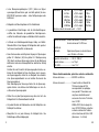
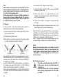
To measure diodes or other semi-conductor paths, proceed as
follows (observe without fail the following illustrations):
1. Connect the black test lead to the COM socket and the red test
lead to the V/Ohm socket.
2. Position the rotary switch to "–I–".
3. With diode test, the indicated value refers to the forward voltage
of a silicon semiconductor path (Si P-N junction).
black
measuring
red
measuring
Conducting direction
red
measuring
black
measuring
Blocking direction
Now connect the test probes to the measurement points, an unpowered semiconductor circuit, with the red probe to the anode and
the black probe to the cathode (these usually being indicated by a
coloured ring, spot or similar).
If you test a diode path in the conducting direction, you will measure a voltage of from approx. 0.6 V (silicon) to 1,5 V (i.e. 600 mV to
1500 mV), provided that the diode path is not defective.
If the test leads are interchanged, i.e. red to the cathode and black
to the anode, then the non-conducting direction of the diode path
is checked.
40
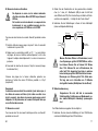
For measurement of DC voltages proceed as follows:
1. Connect the red test lead to the V/Ohm socket and the black
test lead to the COM socket.
2. Set the rotary switch to "V="; range-switching occurs automatically, i.e. the measuring instrument matches itself automatically to the measured value.
3. Connect the test probes to the object to be measured (load,
circuit, etc.).
4. The respective polarity of the measured value is shown in the
display, together with the present measured value.
Each of the five DC voltage ranges DCV offers an input resistance
of 10 MOhm; in the 400 mV range this rises to more than 4 GOhm
(4000 MOhm). The AC voltage ranges have an input impedance of
10 MOhm min. in parallel with < 20 pF (AC-coupled).
When "-" appears in front of the DC voltage measured value, the
measured voltage is negative (or the test leads are reversed).
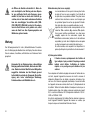
Notes!
Because the measurement input is very sensitive, it may be
that with unconnected test leads (not connected with a test
circuit) random measured values may be displayed. This
"manifestation" is normal and disappears as soon as a measurement is performed.
B AC voltage measurement
The maximum permitted input value, 600 V DC or
V AC rms max., must not be exceeded under any
circumstances..
Do not touch any circuits or circuitry components
when measuring voltages higher than 25 V AC rms
or 35 V DC.
37