1
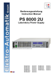
Labornetzgeräte Laboratory Power Supplies PS 2000 B Triple PS 2342-06B: PS 2342-10B: PS 2384-03B: PS 2384-05B: 39 200 120 39 200 121 39 200 125 39 200 126 DE Allgemeines Impressum Elektro-Automatik GmbH & Co. KG Sicherheitshinweise Helmholtzstrasse 31-33 41747 Viersen Germany Telefon: 02162 / 37850 Fax: 02162 / 16230 Web: www.elektroautomatik.de Mail: [email protected] © Elektro-Automatik Nachdruck, Vervielfältigung oder auszugsweise, zweckentfremdete Verwendung dieser Bedienungsanleitung sind verboten und können bei Nichtbeachtung rechtliche Schritte nach sich ziehen. • Das Gerät ist nur mit der angegebenen Netzspannung zu betreiben! • Keine mechanischen Teile, insbesondere aus Metall, durch die Lüftungsschlitze in das Gerät einführen! • Die Verwendung von Flüssigkeiten aller Art in der Nähe des Gerätes ist zu vermeiden, diese könnten in das Gerät gelangen! • Keine Spannungsquellen an den Ausgang des Gerätes anschließen, die die Nennspannung des Gerätes übersteigen können! • Keine Spannungsquellen mit umgekehrter Polarität an den Ausgang des Gerätes anschließen! • Nach dem Ausschalten des Ausganges bzw. des Gerätes kann am Ausgang noch berührungsgefährliche Spannung anliegen, zumindest für eine gewisse Zeit. • Achtung! Die Gehäuseunterseite erwärmt sich bei längerem Betrieb mit hoher Last. Bedienungsanleitung PS 2000 B Triple Serie Stand: 22.05.2012 3 Inhaltsverzeichnis DE Seite Einleitung.......................................................................................................................................................................... 5 Installation........................................................................................................................................................................ 5 Netzanschluß................................................................................................................................................................ 5 Lasten anschließen....................................................................................................................................................... 5 Ausgänge 1 & 2 (Output 1, Output 2)......................................................................................................................... 5 Ausgang 3 (Output 3)................................................................................................................................................. 5 Technische Daten............................................................................................................................................................. 6 Lieferumfang................................................................................................................................................................. 6 Ansichten....................................................................................................................................................................... 7 Bedien- und Anschlußelemente.................................................................................................................................... 8 Bedienung........................................................................................................................................................................ 8 Anzeige .................................................................................................................................................................. 8 Abkürzungen in der Anzeige...................................................................................................................................... 8 Fehlermeldungen....................................................................................................................................................... 8 Tasten............................................................................................................................................................................ 9 Tasten Preset ...................................................................................................................................................... 9 Tasten On/Off ...................................................................................................................................................... 9 Weitere Bedienelemente............................................................................................................................................... 9 Sollwerte einstellen....................................................................................................................................................... 9 Bedienfeldsperre (LOCK)............................................................................................................................................ 10 Tracking-Modus........................................................................................................................................................... 10 Verhalten des Gerätes.................................................................................................................................................... 10 Einschalten mit dem Netzschalter............................................................................................................................... 10 Überspannung............................................................................................................................................................. 10 Überhitzung................................................................................................................................................................. 10 Überstrom.....................................................................................................................................................................11 Weitere Anwendungen....................................................................................................................................................11 Reihenschaltung der Ausgänge 1 & 2..........................................................................................................................11 Reihenschaltung von Geräten......................................................................................................................................11 Parallelschaltung der Ausgänge 1 & 2.........................................................................................................................11 Parallelschaltung mehrerer Geräte..............................................................................................................................11 Fernsteuerung..............................................................................................................................................................11 Verschiedenes................................................................................................................................................................ 12 Firmwareaktualisierung............................................................................................................................................... 12 Hilfe bei Problemen........................................................................................................................................................ 12 4 Stand: 22.05.2012 Bedienungsanleitung PS 2000 B Triple Serie DE Über das Gerät 1. Einleitung Die Labornetzgeräte der Serie PS 2000 B Triple sind sehr kompakte und robuste Geräte, die auf kleinem Raum eine Vielzahl von interessanten Möglichkeiten bieten. Die Geräte eignen sich aufgrund des berührungsfreien Aufbaus und der einfachen Handhabung besonders für den Einsatz in Schule, Ausbildung, Werkstatt oder Labor. Es sind Modelle mit 2x 100W oder 2x 160W Nennleistung verfügbar. Jedes Modell bietet zwei getrennte, in Spannung und Strom separat einstellbare Hauptausgänge mit 0...42V oder 0...84V und einen Zusatzausgang, dessen Spannung über einen Trimmer zwischen 3...6V variiert werden kann. Über die gängigen Funktionen von Netzgeräten hinaus können zum Beispiel die Tasten und Einsteller gegen ungewollte Veränderung der Sollwerte gesperrt oder eine Abschaltung des Ausgangs bei Überschreiten einer einstellbaren Spannungs- bzw. Stromschwelle erreicht werden. Als Hilfe für die Einstellung der Spannung und des Stromes bei Reihen- oder Parallelschaltung dient der sogenannte Trackingmodus (siehe Abschnitt 4.6), wo Ausgang 2 dem Ausgang 1 folgt. 2.2.2 Ausgang 3 (Output 3) Dieser Zusatzausgang ist seperat zu betrachten. Es ist der oberste der drei Ausgänge und nur die Spannung ist mittels des Trimmers, der sich hinter der Öffnung zwischen den Ausgangsbuchsen befindet, von ca. 3V bis ca. 6V einstellbar. Der Ausgang liefert ca. 12W. Bei 6V sind dann etwa 2A verfügbar und bei 3V etwa 4A. Wird der Strom überschritten, erlischt die LED und die Spannung bricht, je nach Last, bis auf 0V zusammen. Parallelschaltung mit einem oder beiden Hauptausgängen (1 & 2) ist nicht zulässig! Weiterhin ist eine fest integrierte USB-Schnittstelle vorhanden, die es ermöglicht, das Gerät mittels eines PCs und einer Software fernzusteuern und zu überwachen. 2. Installation 2.1 Netzanschluß Das Gerät wird über das beiliegende Netzanschlußkabel angeschlossen und geerdet. Deshalb darf das Gerät nur an einer Schutzkontaktsteckdose betrieben werden. Diese Maßnahme darf nicht durch Verwendung einer Anschlussleitung ohne Schutzleiter unwirksam gemacht werden. Die Absicherung des Gerätes erfolgt über eine 5 x 20mm Schmelzsicherung, die sich in der Netzbuchse in einer Schublade befindet. Wert siehe Typenschild oder Sicherungsaufdruck. 2.2 Lasten anschließen Die Lastausgänge befinden sich auf der Vorderseite des Gerätes. Die Ausgänge sind nicht über eine Sicherung abgesichert. Um Beschädigungen des Verbrauchers zu vermeiden, sind die für den Verbraucher zulässigen Nennwerte stets zu beachten. 2.2.1 Ausgänge 1 & 2 (Output 1, Output 2) Hauptausgang 1 ist der unterste und Hauptausgang 2 ist der mittlere der drei Ausgänge (siehe „Bild 1“ auf Seite 7). Ausgang 1 wird über das linke Bedienfeld und Ausgang 2 über das rechte Bedienfeld eingestellt. Strom und Spannung, sowie die zum jeweiligen Ausgang gehörigen Überspannungs- und Überstromabschaltschwellen können mit den Drehknöpfen zwischen 0...100% Nennwert (für Sollwerte) bzw. 0...110% Nennwert (für Abschaltschwellen) eingestellt werden. Die Einstellung erfolgt kontinuierlich mit der in Abschnitt 4.4 angegebenen Schrittweite. Die Ausgänge sind spannungs-, strom- und leistungsbegrenzt, dauerkurzschlußfest und können miteinander in Reihe oder parallelgeschaltet werden, um den Ausgangsstrom bzw. die Ausgangsspannung zu erhöhen. Bedienungsanleitung PS 2000 B Triple Serie Stand: 22.05.2012 5 DE Über das Gerät 3. Technische Daten Netzeingang Eingangsspannung Frequenz Sicherung Leistungsfaktor Leistungsaufnahme im Leerlauf Ausgang 1 & 2 - Spannung Einstellbereich Stabilität Netzausregelung ±10% ∆UE Stabilität bei 0…100% Last Restwelligkeit BWL 20MHz Genauigkeit* Überspannungsschutz Ausregelzeit 10….90% Last Softstart Ausgang 1 & 2 - Strom Einstellbereich Stabilität Netzausregelung ±10% ∆UE Stabilität bei 0…100% ∆UA Restwelligkeit Genauigkeit* Ausgang 1 & 2 - Leistung Wirkungsgrad Nennleistung Pnenn Ausgang 3 Einstellbereich Leistung Stabilität Netzausregelung ±10% ∆UE Stabilität bei 0…100% Last Restwelligkeit BWL 20MHz Nennstrom Verschiedenes Betriebstemperatur Lagertemperatur Luftfeuchtigkeit rel. Abmessungen (BxHxT) Gewicht Kühlung Sicherheit EMV-Normen Überspannungskategorie Schutzklasse Artikelnummer PS 2342-06B PS 2342-10B PS 2384-03B PS 2384-05B 100…240V ±10% 45…65Hz MT 4A > 0.99 24W 100…240V ±10% 45…65Hz MT 6,3A > 0.99 24W 100…240V ±10% 45…65Hz MT 4A > 0.99 24W 100…240V ±10% 45…65Hz MT 6,3A > 0.99 24W 0...42V 0...42V 0...84V 0...84V < 0.02% < 0.02% < 0.02% < 0.02% < 0.15% < 80mVPP / < 9mVRMS ≤ 0.2% 0…46.2V < 2ms max. 200ms < 0.15% < 80mVPP / < 9mVRMS ≤ 0.2% 0…46.2V < 2ms max. 200ms < 0.15% < 60mVPP / < 10mVRMS ≤ 0.2% 0…92.4V < 2ms max. 200ms < 0.15% < 60mVPP / < 10mVRMS ≤ 0.2% 0…92.4V < 2ms max. 200ms 0…6A 0…10A 0…3A 0…5A < 0.05% < 0.05% < 0.05% < 0.05% < 0.15% < 25mAPP / < 9mARMS ≤ 0.2% < 0.15% < 40mAPP / < 15mARMS ≤ 0.2% < 0.15% < 6mAPP / < 2mARMS ≤ 0.2% < 0.15% < 9mAPP / < 3mARMS ≤ 0.2% ≤ 85% 2x 100W ≤ 85% 2x 160W ≤ 85% 2x 100W ≤ 85% 2x 160W 3…6V 12W < 0.02% < 0.1% < 100mVpp 2A @ 6V 4A @ 3V 3…6V 12W < 0.02% < 0.1% < 100mVpp 2A @ 6V 4A @ 3V 3…6V 12W < 0.02% < 0.1% < 100mVpp 2A @ 6V 4A @ 3V 3…6V 12W < 0.02% < 0.1% < 100mVpp 2A @ 6V 4A @ 3V 0….50°C -20….70°C < 80% 282x82x241mm 3,3kg 39200120 0….50°C 0….50°C -20….70°C -20….70°C < 80% < 80% 282x82x241mm 282x82x241mm 3,5kg 3,3kg lüfterlos, natürliche Konvektion EN 60950 EN 61326, EN 55022 Class B Klasse II Klasse I 39200121 39200125 0….50°C -20….70°C < 80% 282x82x241mm 3,5kg 39200126 * Bezogen auf den Nennwert, definiert die Genauigkeit die maximale Abweichung zwischen Sollwert und Istwert. Beispiel: ein 42V-Gerät hat min. 0,2% Spannungsgenauigkeit, das sind 84mV. Bei einem Sollwert von 5V dürfte der Istwert also max. 84mV abweichen, sprich er dürfte 4,92V...5,08V betragen. 3.1 Lieferumfang 1 x Netzgerät 1 x Gedruckte Bedienungsanleitung 1 x Netzkabel (IEC, Schuko) 6 Stand: 22.05.2012 Bedienungsanleitung PS 2000 B Triple Serie DE Über das Gerät 3.2 Ansichten Bild 1 Bedienungsanleitung PS 2000 B Triple Serie Bild 2 Stand: 22.05.2012 7 DE Über das Gerät 3.3 Bedien- und Anschlußelemente Netzschalter Dient zum Einschalten oder Ausschalten des Gerätes. Taster „Preset“ Dienen zur Umschaltung der Anzeigen auf die Sollwerte. Weiterhin wird mit den Tasten die Bedienfeldsperre des jeweiligen Bedienfeldes aktiviert. Siehe Abschnitte 4.4 und 4.5. Erdungsbuchse Die Buchse kann zum Einstecken von 4mm Büschelsteckern (offen oder geschlossen) verwendet werden und ist mit dem Gehäuse verbunden. Sie kann zur Erdung eines angeschlossenen Verbrauchers oder eines der Ausgangspole (Plus oder Minus) genutzt werden. 4. Bedienung 4.1 Anzeige Anzeigen Diese blauen LCD-Anzeigen bietet alle wichtigen Informationen auf einen Blick. Einsteller „Voltage“ Dienen zum Einstellen der Ausgangsspannung für die Ausgänge 1 und 2 oder zur Einstellung der Überspannungsschwelle OVP. Mini-USB-Buchse Dient zum Anschluß des Gerätes an einen PC. Siehe auch Abschnitt 6.5. 4.1.1 Abkürzungen in der Anzeige Die Kürzel in der Anzeige stellen den Status dar und bedeuten folgendes: Einsteller „Current“ CV - Spannungsregelung aktiv (nur bei Ausgang „ein“) Dienen zur Einstellung des Ausgangsstromes für die Ausgänge 1 und 2 oder zur Einstellung der Überstromschwelle OCP. CC - Strombegrenzung aktiv (nur bei Ausgang „ein“) Taster „On/Off“ OT - Übertemperaturfehler Dienen zum Einschalten oder Ausschalten der Hauptausgänge 1 und 2. OCP - Überstromschutz Leistungsausgang 1, gepolt, Sicherheitsbuchsen Remote - Fernsteuerung aktiv (via USB) Die Buchsen können zum Einstecken von 4mm Büschelsteckern (offen oder geschlossen) verwendet werden. Dieser Ausgang ist dem linken Bedienfeld zugeordnet. Leistungsausgang 2, gepolt, Sicherheitsbuchsen Die Buchsen können zum Einstecken von 4mm Büschelsteckern (offen oder geschlossen) verwendet werden. Dieser Ausgang ist dem rechten Bedienfeld zugeordnet. Zusatzausgang 3, gepolt, Sicherheitsbuchsen Die Buchsen können zum Einstecken von 4mm Büschelsteckern (offen oder geschlossen) verwendet werden. Dieser Ausgang kann nur über den Trimmer eingestellt werden, der sich hinter einer Öffnung zwischen den Ausgangsbuchsen befindet. Taster „Tracking“ Dient zur Aktivierung des Tracking-Modus‘. Siehe Abschnitt „4.6 Tracking-Modus“ für Details. 8 Bild 3 Stand: 22.05.2012 Preset V/C - Sollwertanzeige Spannung/Strom aktiv Preset OVP/OCP - Sollwertanzeige OVP/OCP aktiv OVP - Überspannungsschutz Lock - Bedienfeldsperre aktiv 4.1.2 Fehlermeldungen Bei Fehlern wie Überspannung, Überstrom oder Übertemperatur werden das Wort „Error“ und ein Kürzel (OT, OVP, OCP) angezeigt, sowie die Ausgangsspannung abgeschaltet. Diese Anzeige bleibt solange bestehen, bis der Anwender die Taste „On/Off“ betätigt, als Bestätigung der Zurkenntnisnahme. Bei einem Übertemperaturfehler kehrt die Ausgangsspannung nach Abkühlung automatisch wieder zurück, bei anderen Fehlern muß der Ausgang durch den Anwender wieder eingeschaltet werden. Weitere Anzeigen sind an bestimmte Bedienungsmodi gebunden und werden in den folgenden Abschnitten erläutert. Die Hauptausgänge 1 und 2 arbeiten separat. Das bedeutet im Fehlerfall eines Ausganges, daß der andere weiterarbeitet. Ausgang 3 bietet keinerlei Fehleranzeige. Bedienungsanleitung PS 2000 B Triple Serie DE Bedienung des Gerätes 4.2 Tasten 4.4 Sollwerte einstellen 4.2.1 Tasten Preset Diese Tasten dienen zum Umschalten in den Preset-Modus und zur Aktivierung/Deaktivierung von LOCK, sofern sich das Gerät nicht im Fernsteuerbetrieb befindet. Betätigung Anzeige 1x Modus Anzeige U/I Sollwert 2x Anzeige OVP/OCP Sollwert Aktivierung/Deaktivierung LOCK (siehe auch 4.5) Anzeige U/I Istwerte 3x 4x Sollwerte und die Abschaltschwellen (OVP/OCP) werden beim Ausschalten des Gerätes nicht gespeichert und sind nach dem Einschalten des Gerätes zurückgesetzt auf Minimum für die Spannung und Maximum für Strom, OVP und OCP. Bei der Einstellung von Strom und Spannung beeinflussen sich die beiden Sollwerte gegenseitig, um die max. Leistung nach Pmax = UIst * IIst nicht zu überschreiten. Das betrifft manuelle Bedienung genauso wie Fernsteuerung. Es gilt für die manuelle Bedienung im Preset-Modus sowie im Normalbetrieb: a) Ist der Ausgang eingeschaltet und Spannungsregelung aktiv (Status „CV“ in der Anzeige) und wird dann der Stromsollwert über ein Limit, berechnet nach der Formel „Stromsollwert = Maximalleistung / Spannungssollwert“, verändert, dann wird der Spannungssollwert automatisch nach der Formel reduziert, um die Maximalleistung einzuhalten. b) Ist der Ausgang eingeschaltet und Stromregelung aktiv (Status „CC“ in der Anzeige) und wird dann der Spannungssollwert über ein Limit, berechnet nach der Formel „Spannungssollwert = Maximalleistung / Stromsollwert“, verändert, dann wird der Stromsollwert automatisch nach der Formel reduziert, um die Maximalleistung einzuhalten. Falls der OCP-Wert gleich dem Stromsollwert ist, hat 4.2.2 Tasten On/Off Diese Tasten dienen zum separaten, manuellen Ein- oder Ausschalten der Hauptausgänge 1 und 2, sofern sich das Gerät nicht im Fernsteuerungsbetrieb befindet. Alle Werte können grob oder fein eingestellt werden. Umschalten erfolgt durch kurzen Druck auf den jeweiligen Drehknopf. Im Normalbetrieb ist standardmäßig Grobeinstellung aktiv. Wenn aber Feineinstellung aktiv ist und keine weitere Sollwerteinstellung mehr getätigt wird, dann stellt es sich nach 10s automatisch auf Grobeinstellung zurück. Die automatische Rückstellung von Feinstellung auf Grobeinstellung findet ebenso beim Wechsel in den PresetModus oder vom Preset-Modus in den Normalbetrieb. Im Tracking-Modus ist die Preset-Taste des rechten Bedienfeldes inaktiv. Die Preset-Anzeige auf dem rechten Display wird durch Bedienung des Tracking-Modus‘ am linken Bedienfeld aktiviert. Siehe auch Abschnitt „4.6 Tracking-Modus“. Der Zustand des jeweiligen Ausganges wird mit dem Statustext (ein) oder Anzeige angezeigt. (aus) in der zugehörigen Die Tasten können durch den Zustand LOCK blockiert sein. Siehe auch „4.5 Bedienfeldsperre (LOCK)“. Weiterhin quittieren die Tasten Fehler, die durch den Status „Error“ gemeldet werden. Siehe auch Abschnitt 4.1.2. Im Tracking-Modus ist die On/Off-Taste des rechten Bedienfeldes inaktiv. Ein- und Ausschalten des Ausgangs 2 geschieht dann durch Bedienung des Tracking-Modus‘ am linken Bedienfeld. Siehe auch Abschnitt „4.6 TrackingModus“. 4.3 Weitere Bedienelemente Einsteller Voltage der OCP-Wert Priorität und wird bei Erreichen den Ausgang abschalten! Es gelten folgende konstante Schrittweiten für die manuelle Einstellung, in Abhängigkeit von den Nennwerten des Gerätes: Spannung Nennwert grob fein 42V 1V 0,05V 84V 1V 0,1V Nennwert 3A 5A 6A 10A Strom grob 0,1A 0,1A 0,1A 0,1A fein 0,01A 0,01A 0,01A 0,01A Einstellung der Spannung von Ausgang 3 kann nur mit Hilfe eines Multimeters erfolgen! & Current Die Einsteller dienen zum Einstellen diverser Werte am Gerät. Zuweisung: • Linker Einsteller des Bedienfeldes: Spannung (U) oder Überspannungsschwelle (abhängig vom Modus) des zugeordneten Ausgangs • Rechter Einsteller am Bedienfeld: Strom (I) oder Überstromschwelle (abhängig vom Modus) des zugeordneten Ausgangs Näheres dazu siehe die folgenden Abschnitte. Bedienungsanleitung PS 2000 B Triple Serie Stand: 22.05.2012 9 DE Bedienung des Gerätes 4.5 Bedienfeldsperre (LOCK) Die Bedienfeldsperre LOCK dient zum Schutz vor unabsichtlicher Bedienung, durch die Sollwerte verstellt werden könnten. Während LOCK aktiv ist, kann lediglich die jeweilige Taste Preset betätigt werden, um den Zustand LOCK wieder zu beenden. Diese Bedienfeldsperre kann für das linke und rechte Bedienfeld jeweils separat aktiviert oder deaktiviert werden. Ausnahme: im Trackingmodus ist das rechte Bedienfeld gesperrt und kann auch nur Verlassen des Tracking-Modus‘ wieder entsperrt werden. Während LOCK kann der Ausgang nicht aus- oder eingeschaltet bzw. die Sollwerte verstellt werden! Aktivierung der Bedienfeldsperre geschieht durch dreimaliges Drücken der Preset-Taste, bis folgende Anzeige erscheint: • Der Modus kann auch während der Fernsteuerung über einen Befehl aktiviert bzw. deaktiviert werden • Bei Parallelschaltung werden die Istwerte der Ausgänge auf dem jeweils zugehörigen LCD angezeigt 5. Verhalten des Gerätes 5.1 Einschalten mit dem Netzschalter Nach dem Einschalten des Gerätes wird folgender Zustand hergestellt: • Die Ausgänge sind ausgeschaltet • Die Stromsollwerte der Ausgänge werden auf Maximum und die Spannungssollwerte auf Minimum (=0V) gesetzt • Die Sollwerte der Überspannungs- bzw. Überstromschwellen werden auf Maximum gesetzt • Vor dem letzten Ausschalten bzw. vor einem Netzausfall bestandene Zustände wie LOCK, REMOTE oder TRACKING werden zurückgesetzt. 5.2 Überspannung Bild 4 Es läuft ein Countdown ab. Man hat nun folgende Möglichkeiten: a) Man wartet, bis der Countdown abgelaufen ist. Danach ist das Bedienfeld gesperrt und LOCK aktiv. b) Man betätigt die Taste Preset noch einmal und bricht damit den Countdown ab. LOCK ist danach nicht aktiv. Deaktivierung erfolgt durch erneutes, aber einmaliges Drücken der Taste Preset. Es startet wieder ein Countdown. Läuft er ab, bleibt die Bedienfeldsperre aktiv. Wird der Countdown abgebrochen, durch erneutes Drücken der Taste, wird die Sperre deaktiviert. 4.6 Tracking-Modus Das sog. Tracking (deutsch: Nachführung, Folgen) dient zur gleichzeitigen und gleichwertigen Einstellung der Ausgangsspannung und des Ausgangsstromes beider Hauptausgänge 1 und 2. Dies ist besonders nützlich bei Parallel- oder Reihenschaltung der Ausgänge. Es gilt folgendes: • Tracking kann nur aktiviert bzw. deaktiviert werden, wenn beide Hauptausgänge ausgeschaltet sind • Während des Tracking-Modus‘ ist das rechte Bedienfeld gesperrt • Das linke Bedienfeld dient zur Einstellung von Strom, Spannung und die Schwellwerte OVP und OCP für beide Ausgänge, da die Sollwerte von Bedienfeld links auf das Bedienfeld rechts übernommen werden Ein Überspannungsfehler (OV) kann durch einen internen Fehler (Ausgangsspannung läuft hoch) auftreten oder durch eine zu hohe Spannung von außen. Der Überspannungsschutz wird in beiden Fällen die Spannung des betroffenen Ausgangs (nur Hauptausgang 1 oder 2) abschalten und den Fehler durch den Statustext „Error“ im Display anzeigen. Nach der Abschaltung muß der Fehler zunächst quittiert werden. Siehe auch Abschnitt 4.2.2. Überhöhte Spannung (>120% Nennspannung) von außen ist unbedingt zu vermeiden, da Bauteile im Inneren zerstört werden können! Ist keine Überspannung mehr vorhanden, kann der Ausgang wieder eingeschaltet werden. Bei Parallelschaltung der beiden Hauptausgänge 1 und 2 kann die Ausgangsspannung des einen Ausgangs beim anderen Ausgang einen OV-Fehler hervorrufen, wenn dessen OVP-Schwelle geringer eingestellt ist. Es wird daher bei Parallelschaltung der Ausgänge empfohlen entweder den Tracking-Modus zu aktivieren, durch den die Sollwerte und Schwellen angeglichen werden, oder beide OVP-Schwellenwerte gleich einzustellen. 5.3 Überhitzung Sollte ein Übertemperaturfehler (OT) durch Überhitzung auftreten, wird die Ausgangsspannung des betroffenen Ausgangs abgeschaltet und das Statuskürzel „OT“ im Display angezeigt, zusammen mit dem Text „Error“. Der betroffene Ausgang schaltet sich nach dem Abkühlen automatisch wieder ein. Soll dies nicht geschehen, kann der Ausgang während der Übertemperaturphase manuell mit der Taste „On/Off“ abgeschaltet werden. • Die Sollwerte von Ausgang 2 und deren Anzeige folgen dem Ausgang 1, die Istwerte von Ausgang 2 sind lastabhängig 10 Stand: 22.05.2012 Bedienungsanleitung PS 2000 B Triple Serie DE Bedienung des Gerätes 5.4 Überstrom Bei Überstrom durch eine zu hohe Belastung kann das Gerät auf zwei Arten reagieren: 1. Abschaltung des jeweiligen Ausganges (OCP) oder 2. Begrenzung des Stromes (CC) Um den Ausgang bei Überstrom abzuschalten, muß die Überstromschwelle (OCP) kleiner als die Strombegrenzung (Iset) eingestellt werden weil sonst der Strom nur begrenzt würde. Siehe dazu auch Abschnitt 4.4. 6. Weitere Anwendungen 6.1 Reihenschaltung der Ausgänge 1 & 2 Die beiden Hauptausgänge 1 und 2 können in Reihe geschaltet werden, um die Ausgangsspannung des Gerätes zu erhöhen. Dabei gilt folgendes: • Es findet keine Summenanzeige der Gesamtausgangsspannung auf einer der Anzeigen statt • Die Gesamtausgangsspannung ergibt sich durch die Summe der Ausgangsspannungen der beiden Ausgänge • Der maximale Strom der Reihenschaltung begrenzt sich durch den an beiden Ausgängen am niedrigsten eingestellten Strom, d.h. ist zum Beispiel ein Ausgang auf 0A eingestellt, liefert das Gerät keinen Strom und demzufolge auch keine Ausgangsspannung 6.3 Parallelschaltung der Ausgänge 1 & 2 Die beiden Hauptausgänge 1 und 2 können parallelgeschaltet werden, um den Ausgangsstrom des Gerätes zu erhöhen. Dabei gilt folgendes: • Es findet keine Summenanzeige des Gesamtausgangsstromes auf einer der Anzeigen statt • Der Gesamtausgangsstrom ergibt sich durch die Summe der Ausgangsströme der einzelnen Ausgänge und ist • Der maximale Strom der Parallelschaltung begrenzt sich auf die Summe der an beiden Ausgängen eingestellten Maximalströme Es wird empfohlen, bei Parallelschaltung den Trackingmodus (siehe 4.6) zu aktivieren, um Spannung und Strom gleichmäßig zu halten. Eine Parallelschaltung der Ausgänge 1 oder 2 mit Ausgang 3 ist nicht zulässig, da Ausgang 3 eine wesentlich geringere Ausgangsspannung hat und somit beschädigt werden kann. 6.4 Parallelschaltung mehrerer Geräte Mehrere Geräte möglichst gleichen Typs, aber zumindest gleicher Ausgangsspannung, können an ihren DC-Ausgängen parallelgeschaltet werden, um den Ausgangsstrom zu erhöhen. Es wird empfohlen, bei Reihenschaltung den Trackingmodus (siehe 4.6) zu aktivieren, um Spannung und Strom gleichmäßig zu halten. Man kann parallelgeschaltete Geräte manuell bedienen oder von einem PC aus ferngesteuern. Es wird empfohlen, die Ausgangsspannung bei allen beteiligten Geräten gleich hoch einzustellen und den Strom jeweils auf Maximum. Reihenschaltung der Hauptausgänge 1 oder 2 oder 6.5 Fernsteuerung beider mit Ausgang 3 ist nicht zulässig! 6.2 Reihenschaltung von Geräten Mehrere Geräte gleichen Typs, aber zumindest gleichen Nennstromes, können in Reihe geschaltet werden, um die Maximalspannung zu erhöhen. Dazu wird der DC-PlusAusgang des ersten Gerätes mit dem DC-Minus-Ausgang des nächsten Gerätes verbunden usw. Der DC-Plus-Ausgang des letzten Gerätes ist dann der ReihenschaltungsPlus-Ausgang. Es können aus Sicherheits- und Isolationsgründen nicht beliebig viele Geräte in Reihe geschaltet werden. Der oder die DC-Minus-Pole eines oder mehrerer Ausgänge dürfen nicht mehr als 300V DC gegenüber der Erde (PE) angehoben werden. Die maximal zulässige Reihenschaltungsspannung ist bei 42V-Modellen daher 342V und bei 84V-Modellen ist sie 384V. Wird eine Reihenschaltung realisiert sind besondere Schutz- und Vorsichtsmaßnahmen zu treffen, die den sicheren Betrieb der Geräte gewährleisten. Das Gerät kann über die separat erhältliche, lizenzbehaftete Windows-Software EasyPS2000 und ein USB-Kabel (im Kit mit der Software bereits enthalten) ferngesteuert werden. Für weitere Informationen lesen Sie bitte im Handbuch zur Software EasyPS2000 nach bzw. auf unserer Webseite. Zum Betrieb der Software ist ein Lizenzcode erforderlich, der optional käuflich erworben werden kann und das Gerät in der Software freischaltet. Zum Erwerb des Kits bitte beim Händler melden, der das Gerät geliefert hat bzw. eine E-Mail an [email protected] schicken und Artikelnummer/Seriennummer des Gerätes angeben. Alternativ kann die Fernsteuerung in eigene Software eingebunden werden. Die Dokumentation zum Kommunikationsprotokoll und der USB-Treiber (nur Windows) sind auf Anfrage erhältlich. Beispielcode oder LabView VIs sind nicht verfügbar. Werden Geräte mit unterschiedlichem Nennstrom in Reihe geschaltet, bestimmt das Gerät mit der geringsten Strombelastbarkeit den Maximalstrom der Reihenschaltung. Bei Reihenschaltung darf nur der Plus- oder Minuspol des ersten Gerätes, das mit dem niedrigsten Potential, geerdet werden. Bedienungsanleitung PS 2000 B Triple Serie Stand: 22.05.2012 11 Bedienung des Gerätes DE 7. Verschiedenes 7.1 Firmwareaktualisierung Die Firmware des Gerätes kann bei Bedarf aktualisiert werden. Einzelheiten zur Aktualisierung sind im Handbuch zu der Software EasyPS2000 beschrieben, die im seperat erhältlichen Kit bzw. auf unserer Webseite im Downloadbereich zu finden ist. Das Gerät kann nur über diese Software aktualisiert werden, die den Anwender über die nötigen Schritte instruiert. Für ein Update wird kein Lizenzcode benötigt! 8. Hilfe bei Problemen Problem: Nach dem Einschalten des Gerätes tut sich nichts Gründe: Netzsicherung defekt, anderer Defekt Lösung: Wenn das Gerät keinerlei Reaktion zeigt (Anzeige dunkel), dann überprüfen Sie, ob die Netzsicherung defekt ist. Sie befindet sich auf der Rückseite in einer kleinen „Schublade“ in der Netzeingangbuchse. Die Schmelzsicherung kann optisch bzw. zur Gewißheit mit einem Multimeter auf Durchgang geprüft werden. Ist die Sicherung defekt, so ist sie durch eine gleichen Typs und Wertes zu ersetzen. Zusätzlich sind im Inneren des Gerätes weitere Sicherungen (jeweils auf den beiden Leistungsstufen), die, wenn die Netzsicherung in Ordnung ist, in diesem Fall beide defekt sein müßten. Wechseln der Sicherungen darf nur durch geschultes Personal erfolgen, da das Gerät hierfür zu öffnen ist. Die Sicherungen selbst sind nur durch welche gleicher Größe (5x20mm) und gleichen Typs zu ersetzen (siehe Sicherungsaufdruck). Besteht das Problem weiterhin oder ist keine Sicherung defekt, bitte Ihren Händler kontaktieren um weitere Schritte festzulegen. Im Allgemeinen muß das Gerät dann zur Reparatur eingeschickt werden. Problem: Das Gerät zeigt nach dem Einschalten dauerhaft „PS 2000“ in der Anzeige Grund: Fehler bei einer Firmwareaktualisierung Lösung: Gerät aus- und wieder einschalten, ansonsten Firmwareupdate wiederholen. Problem: eine Anzeige zeigt nach dem Einschalten dauerhaft „ERROR“ an Grund: interne Sicherung defekt Lösung: das Gerät hat intern zwei Leistungsmodule, die jeweils eine eigene, interne Feinsicherung besitzen, wovon eine in diesem Fall vermutlich defekt ist. Wechseln der Sicherung darf nur durch geschultes Personal erfolgen, da das Gerät hierfür zu öffnen ist. Die Sicherung selbst ist nur durch eine gleicher Größe (5x20mm) und gleichen Typs zu ersetzen (siehe Sicherungsaufdruck). 12 Stand: 22.05.2012 Bedienungsanleitung PS 2000 B Triple Serie EN General About Elektro-Automatik GmbH & Co. KG Helmholtzstrasse 31-33 41747 Viersen Germany Phone: +49 2162 / 37850 Fax: +49 2162 / 16230 Web: www.elektroautomatik.de Mail: [email protected] © Elektro-Automatik Reprint, duplication or partly, wrong use of this user instruction manual are prohibited and might be followed by legal consequences. Safety instructions • Only operate the device at a mains voltage as stipulated on the type plate! • Never insert mechanical parts, especially from metal, through the air ventilation slots! • Avoid any use of liquids of any kind in the proximity of the device! They might get into it. • Do not connect voltage sources to the device which are able to generate voltages higher than the nominal voltage of the device! • Do not connect a voltage source with reversed polarity to the output! • After the output or even the device has been switched off there can still be dangerous voltage on the output for a certain time! • Attention! The enclosure can heat up during operation and may be hot! Instruction manual PS 2000 B Triple Series Date: 05-22-2012 13 Table of contents EN Page Introduction..................................................................................................................................................................... 15 Installation...................................................................................................................................................................... 15 Mains connection........................................................................................................................................................ 15 Connecting loads......................................................................................................................................................... 15 Outputs 1 & 2........................................................................................................................................................... 15 Output 3.................................................................................................................................................................... 15 Technical specifications.................................................................................................................................................. 16 Scope of delivery......................................................................................................................................................... 16 Views........................................................................................................................................................................... 17 Controls & sockets...................................................................................................................................................... 18 Handling......................................................................................................................................................................... 18 The display . ......................................................................................................................................................... 18 Status tokens............................................................................................................................................................ 18 Error indication......................................................................................................................................................... 18 Pushbuttons................................................................................................................................................................ 19 Pushbuttons Preset . ......................................................................................................................................... 19 Pushbuttons On/Off . ......................................................................................................................................... 19 Further control elements............................................................................................................................................. 19 Adjusting set values.................................................................................................................................................... 19 Control panel lock (LOCK).......................................................................................................................................... 20 Tracking mode............................................................................................................................................................. 20 Behaviour of the device.................................................................................................................................................. 20 Switching on by power switch..................................................................................................................................... 20 Overvoltage................................................................................................................................................................. 20 Overtemperature......................................................................................................................................................... 20 Overcurrent................................................................................................................................................................. 20 Other applications.......................................................................................................................................................... 21 Series connection of outputs 1 & 2.............................................................................................................................. 21 Series connection of several units............................................................................................................................... 21 Parallel connection of outputs 1 & 2............................................................................................................................ 21 Parallel connection of several units............................................................................................................................. 21 Remote control............................................................................................................................................................ 21 Miscellaneous................................................................................................................................................................. 22 Firmware updates........................................................................................................................................................ 22 Trouble-shooting............................................................................................................................................................. 22 Hardware problems..................................................................................................................................................... 22 14 Date: 05-22-2012 Instruction manual PS 2000 B Triple Series EN About the device 1. Introduction The laboratory power supplies of the series PS 2000 B Triple are very compact and rugged devices and incorporate interesting features within small dimensions. The contactless design makes them ideally suited for operation in schools, educational facilities, workshops or laboratories. The series offers models with 2x 100W or 2x 160W nominal power. Every model offers two seperated outputs with adjustable output voltage and current, plus an auxiliary output which can be adjusted in a range of 3...6V by a trimmer. 2.2.2 Output 3 This output is auxiliary and totally seperated from the other two outputs. It can only be adjusted by the trimmer that is accessible through the hole in the front, between the output sockets. The voltage is adjustable in a range of approx. 3...6V. The output power is approx. 12W, resulting in approx. 2A at 6V or approx. 4A at 3V. If the limit is exceeded, the LED will go out and the voltage will drop, depending on the load. Parallel connection with one or both main outputs (1 & 2) is not allowed! Apart from standard functions of power supplies the user can lock pushbuttons and knobs against unintentional use or define thresholds for an automatic output cut-off in case of overcurrent or overvoltage. All models feature a built-in USB interface, which can be used to remotely control and monitor the device by a PC. 2. Installation 2.1 Mains connection The unit is grounded via the mains cord. Thus it must only be operated at a mains socket with grounding contact. This connection must not be interrupted by an extension cable without ground conductor! The unit is fused with a 5 x 20mm safety fuse, which is accessible inside the mains socket in a small „drawer“. For value see fuse imprint or device type label. 2.2 Connecting loads The power outputs are located on the front of the device. The outputs are not fused! In order to avoid damage to the load application, always mind for the supply voltage of the load. 2.2.1 Outputs 1 & 2 Main output 1 is the lowermost one and main output 2 is the middle one of the three outputs (see „Figure 1“ on page 17). Output 1 is controlled with the left-hand control panel and output 2 with the right-hand one. Voltage and current, as well as the related overcurrent and overvoltage cut-off thresholds can be adjusted with the rotary knobs within 0...100% nominal values (for set values) and 0...110% nominal values (for thresholds). The adjustment works continuously and with the step width as given in section 4.4. The outputs are limited to nominal voltage and current and are permanently short-circuit-proof. They can be connected in series or parallel in order to achieve a higher output voltage or output current. The tracking mode (see section „4.6 Tracking mode“) can be helpful for parallel or series operation of the outputs. Instruction manual PS 2000 B Triple Series Date: 05-22-2012 15 EN About the device 3. Technical specifications Mains input Input voltage Frequency Fuse Power factor Power consumption at output off Output 1&2 - Voltage Adjustable range Stability at mains fluctuation ±10% ∆UIN Stability at 0…100% load Ripple BWL 20MHz Accuracy* Overvoltage protection Regulation time 10-90% load Softstart Output 1 & 2- Current Adjustable range Stability at mains fluctuation ±10% ∆UIN Stability at 0…100% ∆UOUT Ripple Accuracy* Output 1 & 2 - Power Efficiency Nominal power Pnom Output 3 Adjustable range Power Stability at mains fluctuation ±10% ∆UIN Stability at 0…100% load Ripple PS 2342-06B PS 2342-10B PS 2384-03B PS 2384-05B 100…240V ±10% 45…65Hz MT 4A > 0.99 24W 100…240V ±10% 45…65Hz MT 6,3A > 0.99 24W 100…240V ±10% 45…65Hz MT 4A > 0.99 24W 100…240V ±10% 45…65Hz MT 6,3A > 0.99 24W 0...42V 0...42V 0...84V 0...84V < 0.02% < 0.02% < 0.02% < 0.02% < 0.15% < 80mVPP / < 9mVRMS ≤ 0.2% 0…46.2V < 2ms max. 200ms 0 0…6A < 0.15% < 80mVPP / < 9mVRMS ≤ 0.2% 0…46.2V < 2ms max. 200ms 0 0…10A < 0.15% < 60mVPP / < 10mVRMS ≤ 0.2% 0…92.4V < 2ms max. 200ms 0 0…3A < 0.15% < 60mVPP / < 10mVRMS ≤ 0.2% 0…92.4V < 2ms max. 200ms 0 0…5A < 0.05% < 0.05% < 0.05% < 0.05% < 0.15% < 25mAPP / < 9mARMS ≤ 0.2% < 0.15% < 40mAPP / < 15mARMS ≤ 0.2% < 0.15% < 6mAPP / < 2mARMS ≤ 0.2% < 0.15% < 9mAPP / < 3mARMS ≤ 0.2% ≤ 85% 2x 100W ≤ 85% 2x 160W ≤ 85% 2x 100W ≤ 85% 2x 160W 3…6V 12W 3…6V 12W 3…6V 12W 3…6V 12W < 0.02% < 0.02% < 0.02% < 0.02% < 0.1% < 100mVpp 2A @ 6V 4A @ 3V < 0.1% < 100mVpp 2A @ 6V 4A @ 3V < 0.1% < 100mVpp 2A @ 6V 4A @ 3V < 0.1% < 100mVpp 2A @ 6V 4A @ 3V Nominal current Miscellaneous Operation temperature Storage temperature Humidity rel. Dimensions (WxHxD) Weight Cooling Safety EMC standards Overvoltage class Protection class Article number 0….50°C -20….70°C < 80% 282x82x241mm 3,3kg 39200120 0….50°C 0….50°C -20….70°C -20….70°C < 80% < 80% 282x82x241mm 282x82x241mm 3,5kg 3,3kg fanless, natural convection EN 60950 EN 61326, EN 55022 Class B Class II Class I 39200121 39200125 0….50°C -20….70°C < 80% 282x82x241mm 3,5kg 39200126 * Related to the nominal value, the accuracy defines the maximum allowed deviation between set value and actual value. Example: a 42V model has min. 0.2% voltage accuracy, this is 84mV. When setting a voltage of 5V and with an allowed maximum deviation of 84mV, the resulting actual value could be between 4.92V and 5.08V. 3.1 Scope of delivery 1 x Power supply device 1 x Printed instruction manual 1 x Mains cord (Schuko, IEC) 16 Date: 05-22-2012 Instruction manual PS 2000 B Triple Series EN About the device 3.2 Views Figure 1 Instruction manual PS 2000 B Triple Series Figure 2 Date: 05-22-2012 17 EN Operating the device 3.3 Controls & sockets 4. Handling 4.1 The display Power switch This is used to switch the device completely on or off. Pushbuttons „Preset“ These buttons are used to switch the actual values display to set values display. It is also used to activate the control panel lock. See sections 4.4 and 4.5 for details. Displays These blue LCDs present all information at one glance. Knobs „Voltage“ Figure 3 4.1.1 Status tokens The status tokens in the display indicate following: These knobs are used to adjust the voltage of the outputs 1 and 2 or, in preset mode, to adjust the OVP threshold. CV - Voltage regulation active (only if output is „on“) Mini USB socket Preset OVP/OCP - Set value display of OVP/OCP active Here the device is connected to a PC, in order to monitor, remotely control or update the device. See section 6.5. OT - Overtemperature error Knobs „Current“ Remote - Remote control active (via USB) These knobs are used to adjust the current of the outputs 1 and 2 or, in preset mode, to adjust the OCP threshold. Lock - Control panel lock active Pushbuttons „On/Off“ Are used to switch the outputs 1 and 2 on or off. Power output 1, safety sockets, poled The sockets can be used to plug 4mm open or safety Bueschel plugs. The left-hand control panel is dedicated to control this output. Power output 2, safety sockets, poled The sockets can be used to plug 4mm open or safety Bueschel plugs. The right-hand control panel is dedicated to control this output. Auxiliary output 3, safety sockets, poled The sockets can be used to plug 4mm open or safety Bueschel plugs. This output can only be adjusted by voltage and only via a trimmer which is located behind the hole between the output sockets. CC - Current regulation active (only if output is „on“) Preset V/C - Set value display of voltage/current active OCP - Overcurrent protection OVP - Overvoltage protection 4.1.2 Error indication If an error like overvoltage, overcurrent or overtemperature occurs it is displayed in one of the LCDs by the text „Error“ and a token (OT, OCP, OVP) and the output voltage is cut off. The text remains in the display until the user has acknowledged the error with the „On/Off“ button, which will also switch the output off. After an overtemperature error, the output voltage will return automatically and „Error“ will be cleared, unless the output has been switched off by the user meanwhile. Other errors require the user to switch the output on again, in order to continue working with the device. Other display elements are connected to certain operation modes and are explained in the following sections. The main outputs 1 and 2 are working seperately, so in case of an error the other output will continue working. Output 3 does not cause any error indication. Pushbutton „Tracking“ This button used to activate or deactivate the tracking mode. See section „4.6 Tracking mode“ for details. Grounding socket This socket can be used to plug 4mm open or safety Bueschel plugs and is connected to the enclosure. It can used to ground a connected load. 18 Date: 05-22-2012 Instruction manual PS 2000 B Triple Series EN Operating the device 4.2 Pushbuttons 4.4 Adjusting set values 4.2.1 Pushbuttons Preset These button are used to switch to preset mode and for activation/deactivation of the LOCK mode, as long as the unit is not in remote control. Push Display 1x Mode Display of U/I set values 2x Display of OVP/OCP set values Activation/Deactivation of LOCK mode (also see 4.5) Display of U/I actual values again 3x 4x The set values and the cut-off thresholds (OVP/OCP) are not stored when switching off the device and after the next start they are reset to minimum for voltage and maximum for current, OVP and OCP. When adjusting the set values of voltage (U) and current (I), a rule becomes active where both set values adjust each other in order to not exceed the max. power of the device according to Pmax = Uset * Iset. It applies for preset mode and normal operation: a) If the output is on and constant voltage regulation is active („CV“ in the display) and if the current set value is adjusted beyond a certain limit which is defined by the formula: current set value = maximum power / voltage set value, then the voltage set value will be reduced automatically according to the same formula, in order to maintain the maximum power. b) If the output is on and constant current regulation is active („CC“ in the display) and if the voltage set value is adjusted beyond a certain limit which is defined by the formula: voltage set value = maximum power / current set value, then the current set value will be reduced automatically according to the same formula, in order to maintain the maximum power. In tracking mode, the preset button of the right-hand If the OCP value is identical to the current limitation control panel is inactive. The preset display of the righthand display is then controlled via the left-hand control panel. Also see section „4.6 Tracking mode“. 4.2.2 Pushbuttons On/Off These pushbuttons are used to manually and seperately switch the power outputs 1 and 2 on or off, as long as the device is not in remote control. The state of the particular output is indicated by or in the related display. The pushbuttons might be locked by the LOCK state. See „4.5 Control panel lock (LOCK)“. The buttons also acknowledge errors. See section 4.1.2 for details. 4.3 Further control elements Knobs Voltage & Current These rotary knobs have no stop and are used to adjust set values. Assignment: value and if that limitation is reached, the OCP will have priority and switch the output off. Adjusting values manually can be done in fine or coarse steps. Switching between coarse and finde adjustment mode is done by pushing the corresponding knob. Coarse adjustment mode is default. If fine adjustment is selected and if no value has been changed for more than 10 seconds, the adjustment mode will automatically return to coarse. The same happens when switching from normal operation to preset mode or vice versa. Following step widths apply in dependency of the nominal values (also refer to technical specs): Voltage Current Nom. value coarse fine Nom. value coarse fine 42V 1V 0.05V 3A 0.1A 0.01A 84V 1V 0.1V 5A 0.1A 0.01A 6A 0.1A 0.01A 10A 0.1A 0.01A Adjusting the output voltage of output 3 can only be done by measuring it with a multimeter. • Left knob on the control panel: Voltage (U) or overvoltage threshold of the dedicated output, depending on preset mode • Right knob on the control panel: Current (I) or overcurrent threshold of the dedicated output, depending on preset mode, For details read below. Instruction manual PS 2000 B Triple Series Date: 05-22-2012 19 EN Operating the device 4.5 Control panel lock (LOCK) The control panel LOCK is intended to prevent unintentional use of the pushbuttons and knobs. LOCK ist activated or deactivated using the preset button. While LOCK is active, only the particular preset button can be used to deactivate LOCK again. The LOCK condition can be set seperately for the left-hand and right-hand control panels. Exception: the right-hand control panel is locked during tracking mode and can only be unlocked by leaving tracking mode. While LOCK is activated, the output can not be switched off manually, not even in an emergency! Activation is done by pushing the preset button three times until the display shows following: 5. Behaviour of the device 5.1 Switching on by power switch The power switch is located at the front. After the device is started, following situation will be set: • The outputs are off • The current set values are set to maximum and the voltage set values to minimum (i.e. 0V) • The set values of overvoltage and overcurrent protection are set to maximum • Any condition like REMOTE, LOCK or TRACKING is reset. 5.2 Overvoltage An overvoltage error can occur due to an internal defect (output voltage rises uncontrolled) or by a too high voltage from external. The overvoltage protection (OVP) will switch off the voltage of the corresponding output (main output 1 or 2 only) and indicate the error in the display by the text „Error“. This error has to be acknowledged first by the On/ Off pushbutton. Then the display will change to normal display again. Also see section 4.2.2. Figure 4 A countdown will be running. During this countdown you have two options: a) Wait until the countdown has finished. After this, the control panel LOCK is active. b) Push the preset button once again and abort the countdown. LOCK is then not activated. External voltages higher than 120% nominal voltage at the output must be avoided, or else internal components of the device might be destroyed! If the cause of the overvoltage is removed, the output can be switched on again. In parallel connection of the main outputs 1 and 2, the Deactivation is done by pushing button „Preset“, which causes the countdown to run again. If it runs out, LOCK remains active. If the countdown is aborted by pushing the button again, LOCK will be deactivated. output voltage of one output can cause an OV error on the other output if the OVP threshold of the effected output is set lower. In such a case it is recommended to either adjust the OVP thresholds of both outputs to the same value or to use tracking mode, which will handle this matter. 4.6 Tracking mode 5.3 Overtemperature The tracking mode is used to control both main outputs 1 and 2 simultaneously and with identical set values by using only the left-hand control panel. This is especially useful when running these outputs in parallel or series connection. Following applies: • Tracking can only be activated or deactivated if both outputs are switched off • In tracking mode, the right-hand control panel is deactivated • The left-hand control panel (output 1) is used to adjust set values (U, I) and thresholds (OVP, OCP) for both outputs. The values are submitted to the right-hand panel • The set values of output 2 follow the set values of output 1, the actual values are load-depending • Tracking mode can also be activated or deactivated by a command during remote control If the unlikely event of an overtemperature (OT) error occurs by internal overheating, the voltage of the corresponding output is cut off and the status token „OT“ is shown in the related display, together with the text „Error“. The output will automatically switch on again after the unit has cooled down. In case this is not wanted, the output can be manually switched off during the overtemperature period. 5.4 Overcurrent The device can react in two different ways to overload resp. overcurrent: 1. By switching the corresponding output off (OCP) or 2. By limitting the output current (CC) In order to switch the output off, it is required to adjust the OCP threshold (see section 4.4) to lower than the current limitation, because else the current is just limited. • In parallel connection, the actual values of the outputs are indicated on the related display 20 Date: 05-22-2012 Instruction manual PS 2000 B Triple Series EN Operating the device 6. Other applications 6.4 Parallel connection of several units 6.1 Series connection of outputs 1 & 2 Several units of preferrably same type, but at least identical nominal output voltage, can be connected in parallel in order to gain a higher total output current. • There will be no totals formation of the total output voltage on any display Every unit has to be adjusted seperately (manually or remotely by a PC). It is recommended to adjust the output current to the maximum and the output voltage to identical values on every unit. The main outputs 1 and 2 can be connected in series in order to gain a higher output voltage. Following applies: • The total voltage is the sum of the single output voltages • The maximum current is limited to the lowest adjusted current of both outputs. It means, if one output is set to 0A, the unit will not put out voltage and no current during series connection It is recommended to use tracking mode (see 4.6), in order to have the adjusted voltage and current at identical values. Series connection of any or both main outputs 1 and 2 with output 3 is not allowed! 6.2 Series connection of several units Several units of preferrably same type, but at least with identical nominal current, can be connected in series in order to gain a higher total output voltage. To do so, the positive DC output of one unit is connected to the negative DC output of the next unit etc. The pos. DC output of the last unit will then be the positive output of the whole series connection and will have the high potential. 6.5 Remote control The device can be remotely controlled via the USB port by means of a PC and a Windows software called EasyPS2000. The software and a USB cable are included in a seperately available kit. The software requires a license code to unlock the device in the software. The code can be purchased as an option. Further information is available upon request or in the user guide of the EasyPS2000 software, as well as on our website. In order to purchase the kit and the license code, contact your dealer or send an e-mail to [email protected] and state article number and serial number of the device. Alternatively, the device can be controlled remotely by custom software. There is documentation about the communication protocol available upon request, together with the USB driver (Windows only). Example code or LabView VIs are not available. Because of safety and insulation reasons it is not al- lowed to connect an arbitrary number of unit in series. The DC minus pole (black) of any output on any unit must not have a potential of higher than 300V DC against ground The maximum allowed series connection voltage is 342V DC for 42V models and 384V DC for 84V models. Special safety measures are required when working with such high voltages! If units with different nominal current are connected in series, the unit with the lowest nominal current will determine the maximum current of the system. In a series connection, only the positive or negative DC output of the first unit (the one with the lowest potential) may be grounded. 6.3 Parallel connection of outputs 1 & 2 The main outputs 1 and 2 can be connected in parallel in order to gain a higher output current. Following applies: • There will be no totals formation of the total output current on any display • The total current builds from the output current of the single outputs It is recommended to use tracking mode (see ), in order to have the adjusted voltage and current at identical values. In parallel connection of the main outputs 1 and 2, the output voltage of one output can cause an OV error on the other output. See section 5.2 for details. Instruction manual PS 2000 B Triple Series Date: 05-22-2012 21 Operating the device EN 7. Miscellaneous 7.1 Firmware updates The device firmware can be updated if necessary. Details about firmware updates and the procedure are in the user guide of the software , which can be found in the seperately available software kit or on our website. Only this software can be used to update a PS 2000 B unit. The update feature of the software does not require the license code. 8. Trouble-shooting 8.1 Hardware problems Problem: After switching the device on nothing happens Reason(s): Input fuse broken, other defect Solution: If the display remains dark, check the input fuse. It is located inside the input socket on the rear, in a little „drawer“. It can be checked visually or by means of a multimeter. If the fuse is broken, replace with same type and value and try again. If the input fuse is OK, there are two more fuses inside the device, one each on the power stages. In this case both should be blown. Replacing the fuses must only be done by trained technical personnel, because the device has to be opened. The fuses must only replaced by such of same size (5x20mm) and type (see fuse imprint). If the error remains, contact your supplier. In such a case the unit usually has to be returned for repair. Problem: The display only shows „PS 2000“ after switching the device on Reason: An error occured during a firmware update Solutions: Switch off device and on again, if this does not help, try to repeat the firmware update procedure. Problem: After the device was powered, one of the displays shows permanently „ERROR“ Reason: internal fuse broken Solution: the device has two power stages. Each of them has its own internal fuse and one is very likely blown in this case. Replacing the fuse must only be done by trained technical personnel, because the device has to be opened. The fuse must only replaced by one of the same size (5x20mm) and type (see fuse imprint). 22 Date: 05-22-2012 Instruction manual PS 2000 B Triple Series EA-Elektro-Automatik GmbH & Co. KG Entwicklung - Produktion - Vertrieb Helmholtzstraße 31-33 41747 Viersen Germany Telefon: 02162 / 37 85-0 Telefax: 02162 / 16 230 [email protected] www.elektroautomatik.de