1
Dust, chips and noise can be health hazards.
Be sure to wear personal protection gear such as safety
goggles, ear protection and dust mask. Use a suitable dust
collection system.
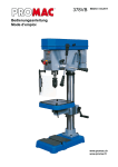
Machine base
Column and bracket assembly
Head assembly
Table
Table bracket lock handle
Table rising handle
3 down feed handles
16mm keyless chuck, B18
MT-3 / B18 arbour
Chuck guard
Drift key
Operating tools
Assembly kit
Operating manual
Spare parts list.
The use of incorrect mains supply or a damaged power cord
can lead to injuries caused by electricity.
4. Machine specifications
4.1 Technical data
Drill capacity in steel (St37)
Tapping capacity
Spindle to column
Spindle travel
Spindle taper
Column diameter
Table size
T-slot size
Distance spindle nose to table
Distance spindle nose to base
Number of speeds
Range of speeds
Overall L/W/H
Net weight
Mains
Output power
Reference current
Extension cord (H07RN-F)
Installation fuse protection
25mm
M12
180mm
100mm
MT-3
80mm
285 x 285 mm
12mm
4.4 Description of the machine
430mm
670mm
variable
270 – 2700 rpm
850x350x1190 mm
125 kg
400V ~3L/PE 50Hz
0,55 kW (0.75 HP) S1
1.5 A
4x1.5mm²
10A
4.2 Noise emission
(Inspection tolerance 4 dB)
Acoustic pressure level (according to EN ISO 11202):
Idling
LpA 69,6 dB(A)
In operation
LpA 79,0 dB(A)
Fig 1
The specified values are emission levels and are not
necessarily to be seen as safe operating levels.
As workplace conditions vary, this information is intended to
allow the user to make a better estimation of the hazards and
risks involved only.
A…..Electrical box
B…..Micro switch for tapping
C…. Down feed handles
D….Column with rack
E….Table rising handle
F….Base
G….Table lock handle
H….Working table
I…..Chuck guard
J….Drill chuck
K….Depth stop
L…. Digital readout
4.3 Content of delivery
5