1
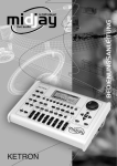
® Vertrieb von JTS-Produkten — Distribution of JTS products Bedienungsanleitung Instruction Manual Mode d’emploi Manual de instrucciones UR-816 D/2 UT-16 GT/2 Funkübertragungssystem für Musikinstrumente Wireless Transmission System for Musical Instruments Système de transmission sans fil pour instruments de musique Sistema de Transmisión Inalámbrica para Instrumentos Musicales DEUTSCH Bevor Sie einschalten … ENGLISH Before switching on … FRANÇAIS Avant toute installation … ESPAÑOL Antes de cualquier instalación ... 2 Wir wünschen Ihnen viel Spaß mit Ihrem neuen Gerät von JTS. Bitte lesen Sie diese Bedienungsanleitung vor dem Betrieb gründlich durch. Nur so lernen Sie alle Funktionsmöglichkeiten kennen, vermeiden Fehlbedienungen und schützen sich und Ihr Gerät vor eventuellen Schäden durch unsachgemäßen Gebrauch. Heben Sie die Anleitung für ein späteres Nachlesen auf. Der deutsche Text beginnt auf der Seite 4. We wish you much pleasure with your new JTS unit. Please read these operating instructions carefully prior to operating the unit. Thus, you will get to know all functions of the unit, operating errors will be prevented, and yourself and the unit will be protected against any damage caused by improper use. Please keep the operating instructions for later use. The English text starts on page 10. Nous vous souhaitons beaucoup de plaisir à utiliser cet appareil JTS. Lisez ce mode d'emploi entièrement avant toute utilisation. Uniquement ainsi, vous pourrez apprendre lʼensemble des possibilités de fonctionnement de lʼappareil, éviter toute manipulation erronée et vous protéger, ainsi que lʼappareil, de dommages éventuels engendrés par une utilisation inadaptée. Conservez la notice pour pouvoir vous y reporter ultérieurement. La version française se trouve page 16. Le deseamos una buena utilización para su nuevo aparato de JTS. Por favor, lea estas instrucciones de uso atentamente antes de hacer funcionar el aparato. De esta manera conocerá todas las funciones de la unidad, se prevendrán errores de operación, usted y el aparato estarán protegidos en contra de todo daño causado por un uso inadecuado. Por favor, guarde las instrucciones para una futura utilización. La versión española comienza en la página 21. 1 2 3 4 8 9 10 5 6 11 7 1 12 13 21 14 19 15 16 22 23 24 17 20 25 18 3 DEUTSCH Auf der ausklappbaren Seite 3 finden Sie alle beschriebenen Bedienelemente und Anschlüsse. 1 Übersicht der Bedienelemente 1.1 Empfänger UR-816D / 2, Vorderseite 1 Empfangsantennen 2 Ein-/Ausschalter POWER 3 Betriebsanzeige 23 Klemmhalterung zur Befestigung des Senders z. B. am Schallbecher eines Blasinstruments 24 Taster ON/ OFF MUTE; zum Einschalten und Stummschalten des Senders kurz drücken, zum Ausschalten gedrückt halten, bis Status-LED (25) erlischt 25 Status-LED leuchtet: Sender in Betrieb blinkt: Sender stummgeschaltet Farbe grün: Batterie in Ordnung Farbe rot: Batterie schwach 4 Wahlschalter für den Empfangskanal 5 LED RF zeigt den Empfang eines Funksignals an (rot oder grün) 2 6 LED AF zeigt den Empfang eines Tonsignals an Die Geräte (Sender, Empfänger und Netzgerät) entsprechen allen relevanen Richtlinien der EU und sind deshalb mit gekennzeichnet. 7 Lautstärkeregler VOL 1.2 Empfänger UR-816D / 2, Rückseite 8 Wahlschalter OUTPUT LEVEL 0 dB/-20 dB zum Einstellen des Pegels für den XLR-Ausgang (9) 9 Symmetrisch beschalteter XLR-Ausgang 10 Asymmetrisch beschalteter Ausgang als 6,3-mmKlinkenbuchse 11 Zugentlastung für das Anschlusskabel vom Netzgerät: Das Kabel um den Haken führen, damit der Stecker nicht versehentlich aus der Buchse (12) gezogen werden kann. 12 Stromversorgungsbuchse DCV INPUT 12 – 18 V zum Anschluss des beiliegenden Netzgerätes WARNUNG Das Netzgerät wird mit lebensgefährlich hoher Netzspannung versorgt. Nehmen Sie deshalb niemals selbst Eingriffe am Netzgerät vor. Durch unsachgemäßes Vorgehen besteht die Gefahr eines elektrischen Schlages. Beachten Sie auch unbedingt folgende Punkte: G Die Geräte sind nur zur Verwendung im Innenbereich geeignet. Schützen Sie sie vor Tropf- und Spritzwasser, hoher Luftfeuchtigkeit und Hitze (zulässiger Einsatztemperaturbereich 0 – 40 °C). G Nehmen Sie den Empfänger nicht in Betrieb und trennen Sie das Netzgerät sofort vom Stromnetz, wenn: 1. sichtbare Schäden an den Geräten oder am Netzkabel vorhanden sind, 2. nach einem Sturz oder Ähnlichem der Verdacht auf einen Defekt besteht, 3. Funktionsstörungen auftreten. Lassen Sie die Geräte in jedem Fall in einer Fachwerkstatt reparieren. G Eine beschädigtes Netzkabel des Netzgerätes darf nur durch eine Fachwerkstatt ersetzt werden. G Ziehen Sie den Netzstecker des Netzgerätes nie am Kabel aus der Steckdose, fassen Sie immer am Stecker an. G Verwenden Sie für die Reinigung nur ein trockenes, weiches Tuch, niemals Wasser oder Chemikalien. G Werden die Geräte zweckentfremdet, nicht richtig angeschlossen, falsch bedient oder nicht fachgerecht repariert, kann keine Haftung für 1.3 Sender UT-16GT / 2 13 6,3-mm-Klinkenadapter; zum Anschluss einer E-Gitarre diesen auf den 3,5-mm-Klinkenstecker (14) des Senders stecken 14 3,5-mm-Klinkenstecker; am Ring-Kontakt liegt eine Gleichspannung zur Versorgung des Mikrofons an 15 Sicherungsring zum Festschrauben des Aufsteckmikrofons (22) oder Klinkenadapters (13) 16 Sockel zur Befestigung der Klemmhalterung (23) 17 Wahlschalter für den Sendekanal 18 Sendeantenne 19 Regler GAIN zum Einstellen der Eingangsempfindlichkeit des Senders 20 Kappe zur Abdeckung des Batteriefachs (3 Stück mitgeliefert) 21 Mikrofonkapsel 22 Aufsteckmikrofon 4 Hinweise für den sicheren Gebrauch Sollen die Geräte endgültig aus dem Betrieb genommen werden, übergeben Sie sie zur umweltgerechten Entsorgung einem örtlichen Recyclingbetrieb. 3 Einsatzmöglichkeiten Der Sender UT-16GT / 2 und der Empfänger UR816D / 2 bilden ein Funkübertragungssystem für Musikinstrumente. Der sehr kompakte Sender kann direkt in die Ausgangsbuchse einer E-Gitarre gesteckt werden oder, mit dem mitgelieferten Mikrofon und der Klemmhalterung versehen, z. B. am Schallbecher eines Blasinstruments befestigt werden. So erhält der Musiker eine maximale Bewegungsfreiheit auf der Bühne. Das Funksystem überträgt im UHF-Frequenzbereich 740 – 764 MHz auf 16 festen Kanälen. Die Übertragungsreichweite hängt von den örtlichen Gegebenheiten ab und kann bis zu 60 m betragen. Der in Diversity-Technik, d. h. mit zwei unabhängigen Empfangsantennen, ausgeführte Empfänger garantiert eine zuverlässige Funkübertragung. Zur Unterdrückung von Störgeräuschen in den Sendepausen ist das System mit einer Rauschsperre (noise squelch) ausgestattet. 3.1 Konformität und Zulassung des Senders Hiermit erklärt MONACOR INTERNATIONAL, dass sich das Gerät UT-16GT / 2 in Übereinstimmung mit den grundlegenden Anforderungen und den übrigen einschlägigen Bestimmungen der Richtlinie 1999/5/EG befindet. Die Konformitätserklärung kann im Internet über die Homepage von JTS (www.jts-germany.de) abgerufen werden. Dieses Gerät darf in folgenden Ländern betrieben werden: DE Links zu den nationalen Behörden finden Sie über die folgende Internetadresse: www.cept.org → ECC → Topics → Short Range Devices (SRD) and other R&T TE sub-classes → EFIS and National Frequency Tables 4 DEUTSCH daraus resultierende Sach- oder Personenschäden und keine Garantie für die Geräte übernommen werden. Inbetriebnahme 4.1 Empfänger aufstellen Die beste Übertragungsqualität erhält man, wenn der Empfänger in Höhe des Senders platziert wird (ca. 1 m über dem Boden) und freie Sicht zum Sender besteht. Die beiden Empfangsantennen (1) senkrecht nach oben ausrichten. Für die Rackmontage ist mit dem DR-900SET ein 482-mm-Einbaurahmen (19″) als Zubehör erhältlich, in dem zwei UR-816D / 2 Platz finden. Mit der dazugehörenden Blende lässt sich bei der Verwendung nur eines Empfängers der nicht benötigte Montageplatz abdecken. 4.2 Empfänger anschließen 1) Den Ausgang des Empfängers mit dem Eingang z. B. eines Mischpultes, Verstärkers oder vorgeschalteten Effektgeräts verbinden. Je nach Art des Eingangs den symmetrisch beschalteten XLR-Ausgang (9) oder die asymmetrisch beschaltete 6,3-mm-Klinkenbuchse (10) verwenden. Der Pegel am XLR-Ausgang kann für den Anschluss an Eingänge für Mikrofone über den Schalter OUTPUT LEVEL (8) um 20 dB reduziert werden. 2) Das beiliegende Netzgerät mit der Kleinspannungsbuchse „DCV INPUT 12 – 18 V“ (12) verbinden und sein Netzkabel mit einer Netzsteckdose (230 V~/ 50 Hz). Das Gerät UT-16GT / 2 muss im Gebiet der Bundesrepublik Deutschland eine Frequenzzuteilung (kostenpflichtig) erhalten. Die Formulare und Hinweise zur Anmeldung finden Sie im Internet auf der Seite der Bundesnetzagentur (www.bundesnetzagentur.de). 3) Damit der Stecker des Netzgerätes nicht versehentlich aus der Buchse (12) gezogen werden kann, zur Zugentlastung das Kabel um den Haken (11) führen. In anderen Ländern muss eine entsprechende Genehmigung beantragt werden. Informieren Sie sich bitte vor der Inbetriebnahme des Geräts außerhalb Deutschlands bei der MONACOR-Niederlassung oder der entsprechenden Behörde des Landes. Der Sender wird von einer 1,5-V-Batterie (Alkaline) der Größe Micro (AAA) versorgt. Zum Einlegen der Batterie die Batteriefachabdeckung (20) nach unten aufschieben. Beim Einlegen der Batterie unbedingt die im Batteriefach aufgedruckte Polari- 4.3 Stromversorgung des Senders 5 DEUTSCH tät beachten. Die Kappe zur Batteriefachabdeckung wieder aufsetzen und nach oben schieben, bis sie einrastet. Es werden drei verschiedenfarbige Kappen mitgeliefert. Wird der Sender längere Zeit nicht benutzt, sollte die Batterie herausgenommen werden, um Schäden des Gerätes durch ein eventuelles Auslaufen der Batterie zu vermeiden. Verbrauchte Batterien dürfen nicht im Hausmüll entsorgt werden. Geben Sie sie nur in den Sondermüll (z. B. Sammelbehälter bei Ihrem Fachhändler). 4.4 Sender an eine E-Gitarre anschließen Zum Anschluss des Senders an eine E-Gitarre: 1) Den 6,3-mm-Klinkenadapter (13) auf den 3,5-mm-Klinkenstecker (14) des Senders aufstecken und mit dem Sicherungsring (15) verschrauben. 4.5 Sender mit dem Mikrofon nutzen Zur Verwendung des Senders mit dem mitgelieferten Mikrofon: 1) Das Mikrofon (22) auf den 3,5-mm-Klinkenstecker (14) des Senders aufstecken und mit dem Sicherungsring (15) verschrauben. 2) Die Klemmhalterung (23) von unten auf den gitarrenförmigen Sockel (16) schieben. 3) Die Klemmhalterung am Instrument befestigen. Abbildung 7 zeigt die Montage am Schallbecher eines Saxofons. Die Klemmbacken sind zur Schonung des Instrumentes gummiert. 4) Die Mikrofonkapsel (21) auf die Schallquelle ausrichten. Wie mit den Pfeilen in Abb. 4 angedeutet, lässt sich das Mikrofon um zwei Achsen neigen. Zusätzlich kann es auch durch Drehen auf dem Klinkenstecker geschwenkt werden. 2) Den Sender mit der Ausgangsbuchse der Gitarre verbinden. Der Stecker am Sender kann im Winkel verstellt werden, er rastet in 22,5°Schritten ein. Dadurch passt der Sender optimal bei Anschlussbuchsen auf der Oberseite des Korpus (Abb. 5) und an der Zarge der Gitarre (Abb. 6). 3) Damit der Sender sich nicht während des Spielens unkontrolliert in der Buchse dreht, kann die Sendeantenne (18), z. B. wie in Abbildung 6, mit dem beiliegenden Halter (26) an der Zarge der Gitarre fixiert werden. 5 Bedienung 5.1 Wahl der Sende- und Empfangsfrequenz Die Funkübertragung erfolgt in dem Frequenzbereich 740 – 764 MHz auf 16 festen Kanälen (Frequenzen der Kanäle Kapitel 6.1). Sender und Empfänger müssen auf den gleichen Kanal eingestellt sein, anderenfalls ist keine Signalübertragung möglich. 6 26 5.1.1 Frequenz am Empfänger einstellen Da es möglich ist, dass am Einsatzort einige Frequenzen bereits durch andere Nutzer von Funksystemen belegt sind, sollte zunächst bei ausgeschaltetem Sender der Empfänger auf den gewünschten Kanal eingestellt werden. Wird auf der Frequenz schon ein Signal empfangen [die LED RF (5) am Empfänger leuchtet], sollte zur Vermeidung gegenseitiger Störung ein anderer Kanal aus- 1) Den Empfänger mit dem Schalter POWER (2) einschalten. Die Betriebsanzeige (3) leuchtet. 2) Mithilfe des dem Sender beiliegenden Trimmschlüssels oder eines kleinen Schraubendrehers über den Drehschalter CH (4) einen freien Kanal einstellen. Beispiel: Kanal 12 ist eingestellt. 5.1.2 Frequenz am Sender einstellen 1) Den Sender mit der Taste ON/ OFF MUTE (24) einschalten. Die LED (25) leuchtet grün. Leuchtet sie rot, ist die Batterie fast verbraucht und muss bald ausgewechselt werden ( Kapitel 4.3). 2) Mithilfe des beiliegenden Trimmschlüssels den Drehschalter CH (17) auf den Kanal des Empfängers einstellen. Die LED RF (5) am Empfänger sollte jetzt rot oder grün leuchten (abhängig davon, über welche Antenne empfangen wird). Ist dies nicht der Fall, überprüfen, ob: – der Empfänger eingeschaltet ist – die Entfernung zum Empfänger zu groß ist oder sich Hindernisse in der Übertragungsstrecke befinden, die das Funksignal abschirmen können Zusätzlich zur LED RF (5) sollte nun die LED AF (6) am Empfänger leuchten, wenn ein Ton gespielt wird und der Ton sollte über die Verstärkeranlage zu hören sein. Leuchtet die LED AF nicht und ist der Ton zu leise, den Regler GAIN im Uhrzeigersinn weiter aufdrehen. Ist der Ton verzerrt, den Regler etwas zurückdrehen. DEUTSCH gewählt werden. Zur Einstellung des Kanals folgende Schritte durchführen: 6) Mit dem Regler VOL (7) den Ausgangspegel des Empfängers auf den Eingang des angeschlossenen Verstärkers oder Mischpultes abstimmen. Zusätzlich kann bei Verwendung des XLR-Ausgangs der Ausgangspegel mithilfe des Schalters OUTPUT LEVEL (8) um 20 dB gesenkt werden (z. B. für den Anschluss an einen Mikrofoneingang). 5.3 Geräte ausschalten Nach dem Gebrauch und, um die Batterie zu schonen, in längeren Nutzungspausen den Sender ausschalten. Dazu die Taste ON/ OFF MUTE (24) ca. 2 s lang gedrückt halten bis die LED (25) erlischt. Für kürzere Spielunterbrechungen die Taste nur kurz drücken, die LED blinkt dann und der Sender ist bis zum erneuten Drücken der Taste stummgeschaltet. Den Empfänger mit dem Schalter POWER (2) ausschalten. Bei längerem Nichtgebrauch das Netzgerät vom Netz trennen, da es auch bei ausgeschaltetem Empfänger einen geringen Strom verbraucht. – Sender und Empfänger auf denselben Kanal eingestellt sind 5.2 Pegel einstellen 1) Den Empfänger mit dem Schalter POWER (2) einschalten. Die Betriebsanzeige (3) leuchtet. Die angeschlossene Verstärkeranlage einschalten. 2) Den Regler VOL (7) zunächst etwa zur Hälfte aufdrehen. 3) Den Sender mit der Taste ON/OFF MUTE (24) einschalten. Die LED (25) leuchtet grün. Leuchtet sie rot, ist die Batterie fast verbraucht und muss bald ausgewechselt werden ( Kapitel 4.3). 4) Den Regler GAIN (19) mithilfe des beiliegenden Trimmschlüssels zunächst etwa zur Hälfte aufdrehen. 5) Den Lautstärkeregler der Gitarre aufdrehen und einen lauten Akkord anschlagen bzw. einen lauten Ton auf dem Instrument spielen, auf das das Mikrofon gerichtet ist. 7 DEUTSCH 6 Technische Daten Allgemeine Daten Trägerfrequenzen: . . . . . . 740 – 764 MHz, in 16 festen Kanälen ( Kap. 6.1) Audio-Frequenzbereich: . 40 – 18 000 Hz Dynamik: . . . . . . . . . . . . . > 105 dB Empfänger UR-816D / 2 Ausgangsspannung: . . . . 300 mV, Schalter „0 dB“ Ausgangsimpedanz: . . . . 600 Ω Anschlüsse: XLR-Anschluss 1 = Masse 2 = Signal + 3 = Signal - Klirrfaktor: . . . . . . . . . . . . < 0,6 % Einsatztemperatur: . . . . . 0 – 40 °C Sender UT-16GT / 2 Sendeleistung: . . . . . . . . . 10 mW 6,3-mm-Klinkenanschluss Frequenzstabilität: . . . . . . ±10 kHz T = Signal S = Masse Nennhub: . . . . . . . . . . . . . ±48 kHz Eingangsimpedanz: . . . . . 1 MΩ Anschlüsse: 3,5-mm-Klinkenanschluss T = Signal R = Gleichspannung für Mikrofon S = Masse 6,3-mm-Klinkenadapter Stromversorgung: . . . . . . 12 – 18V / 200 mA über beiliegendes Netzgerät an 230 V~/50 Hz Abmessungen: . . . . . . . . . 223 × 40 × 175 mm Gewicht: . . . . . . . . . . . . . . 450 g T = Signal S = Masse Stromversorgung: . . . . . . 1,5-V-Batterie der Größe Micro (AAA), Alkaline Batterie-Lebensdauer: . . . > 7 h Gewicht: . . . . . . . . . . . . . . 30 g Mikrofon Wandler: . . . . . . . . . . . . . Elektret Richtcharakteristik: . . . . . Niere Impedanz: . . . . . . . . . . . . 200 Ω Empfindlichkeit: . . . . . . . . 5 mV/ Pa bei 1 kHz Maximaler Schalldruck: . . 130 dB 6.1 Übertragungsfrequenzen Kanal 1 2 3 4 5 6 7 8 9 10 11 12 13 14 15 16 Frequenz [MHz] 744,250 745,500 746,500 747,125 748,250 749,125 750,500 753,500 754,250 755,875 757,000 758,500 759,000 760,750 761,750 763,250 Änderungen vorbehalten. Diese Bedienungsanleitung ist urheberrechtlich für MONACOR ® INTERNATIONAL GmbH & Co. KG geschützt. Eine Reproduktion für eigene kommerzielle Zwecke – auch auszugsweise – ist untersagt. 8 9 ENGLISH All operating elements and connections can be found on the fold-out page 3. 23 Clamping bracket to fix the transmitter e. g. at the bell of a wind instrument 1 24 Momentary pushbutton ON/OFF MUTE; press it shortly to switch on and to mute the transmitter, for switching off keep it pressed until the status LED (25) will be extinguished Operating Elements 1.1 Receiver UR-816D / 2, front side 1 Receiving antennas 2 POWER switch 3 Power LED 25 Status LED lights up: flashes: green colour: red colour: transmitter in operation transmitter muted battery o. k. low battery 4 Selector switch for the receiving channel 5 LED RF shows the reception of a radio signal (red or green) 6 LED AF shows the reception of an audio signal 7 Volume control VOL 1.2 Receiver UR-816D / 2, rear side 8 Selector switch OUTPUT LEVEL 0 dB/-20 dB to adjust the level for the XLR output (9) 9 Balanced XLR output 10 Unbalanced output as a 6.3 mm jack 11 Pull-relief for the connection cable from the power supply unit: Lead the cable around the hook so that the plug cannot be pulled out of the jack (12) by accident. 2 WARNING The power supply unit is supplied with hazardous mains voltage. Leave servicing to skilled personnel only. Inexpert handling or modification of the unit may cause an electric shock hazard. It is essential to observe the following items: G The units are suitable for indoor use only. Protect them against dripping water and splash water, high air humidity, and heat (admissible ambient temperature range 0 – 40 °C). G Do not set the receiver into operation, and immediately disconnect the power supply unit from the mains socket if 1. there is visible damage to the units or to the mains cable, 2. a defect might have occurred after a drop or similar accident, 3. malfunctions occur. The units must in any case be repaired by skilled personnel. G A damaged mains cable of the power supply unit must only be replaced by the skilled personnel. G Never pull the mains cable to disconnect the mains plug from the mains socket, always seize the plug. 19 Control GAIN to adjust the input sensitivity of the transmitter G For cleaning only use a dry, soft cloth, never use chemicals or water. 20 Cover for the battery compartment (3 pieces supplied) G No guarantee claims for the units and no liability for any resulting personal damage or material damage will be accepted if the units are used for other purposes than originally intended, if they 12 Power supply jack DCV INPUT 12 – 18 V for connection of the supplied power supply unit 1.3 Transmitter UT-16GT/ 2 13 6.3 mm adapter; for connection of an electric guitar connect this adapter to the 3.5 mm plug (14) of the transmitter 14 3.5 mm plug; a DC voltage is present at the ring contact to supply the microphone with power 15 Locking ring to tightly fasten the push-on microphone (22) or 6.3 mm adapter (13) 16 Base to fix the clamping support (23) 17 Selector switch for the transmitting channel 18 Transmitting antenna 21 Microphone cartridge 22 Push-on microphone 10 Safety Notes The units (transmitter, receiver and power supply unit) correspond to all relevant directives of the EU and are therefore marked with . If the units are to be put out of operation definitively, take them to a local recycling plant for a disposal which is not harmful to the environment. 3 Applications The transmitter UT-16GT/ 2 and the receiver UR-816D/ 2 form a wireless transmission system for musical instruments. The extra compact transmitter can directly be connected to the output jack of an electric guitar or, equipped with the supplied microphone and the clamping support, it can be fixed e. g. to the bell of a wind instrument. Thus, the musician obtains a maximum freedom of movement on stage. The wireless system transmits in the UHF frequency range of 740 – 764 MHz on 16 fixed channels. The transmission range depends on the local conditions and may be up to 60 m. The receiver in Diversity technology, i. e. with two independent receiving antennas, ensures a reliable wireless transmission. To suppress interfering noise in the transmitting intervals, the system is equipped with a noise squelch. 3.1 Conformity and approval of the transmitter Herewith, MONACOR INTERNATIONAL declare that the unit UT-16GT/ 2 is in accordance with the basic requirements and the other relevant regulations of the directive 1999 / 5 / EC. The declaration of conformity can be found in the Internet via the JTS home page (www.jts-germany.de). This unit may be operated in the following countries: DE In other countries, it is necessary to apply for a corresponding approval. Prior to operating the unit UT16GT/ 2 outside Germany, please contact the MONACOR subsidiary or the corresponding authorities of the respective country. Links to the national authorities can be found via the following Internet address: www.cept.org → ECC → Topics → Short Range Devices (SRD) and other R&T TE sub-classes → EFIS and National Frequency Tables 4 Setting into Operation 4.1 Setting-up the receiver The best transmission quality is obtained when the receiver is placed at the height of the transmitter (approx. 1 m above the ground) and there are no obstacles between receiver and transmitter. Place the two receiving antennas (1) in a vertical position. For rack mounting, the 482 mm (19″) installation frame DR-900SET is available as an accessory which allows to accommodate two UR-816D/ 2 units. The mounting place which is not required when using one receiver only can be covered with the corresponding panel. ENGLISH are not correctly connected or operated, or not repaired in an expert way. 4.2 Connecting the receiver 1) Connect the output of the receiver to the input e. g. of a mixer, amplifier or effect unit connected ahead. Depending on the type of the input use the balanced XLR output (9) or the unbalanced 6.3 mm jack (10). The level at the XLR output can be attenuated by 20 dB via the switch OUTPUT LEVEL (8) for the connection to inputs for microphones. 2) Connect the supplied power supply unit to the low voltage jack “DCV INPUT 12 – 18 V” (12) and its mains cable to a mains socket (230 V~/ 50 Hz). 3) To prevent accidental disconnection of the plug of the power supply unit from the jack (12), lead the cable around the hook (11) for strain relief. 4.3 Power supply of the transmitter The transmitter is supplied with power by a 1.5 V battery (alkaline) of size AAA. To insert the battery, open the battery compartment cover (20) downwards. When inserting the battery, observe the polarity printed in the battery compartment. Reposition the battery compartment cover and slide it upwards until it locks into place. Three covers of different colours are supplied. If the transmitter is not used for a longer time, the battery should be removed to prevent damage to the unit by possible battery leakage. Never put used batteries in the household waste; always take them to a special waste disposal, e. g. collection container at your retailer. 11 ENGLISH 4.4 Connecting the transmitter to an electric guitar To connect the transmitter to an electric guitar: 1) Mount the 6.3 mm adapter (13) onto the 3.5 mm plug (14) of the transmitter and fasten it with the locking ring (15). 2) Connect the transmitter to the output jack of the guitar. The angle of the plug on the transmitter can be readjusted, it locks into place in steps of 22.5°. Thus, the transmitter optimally fits in case of connection jacks on the upper side of the body (fig. 5) and on the rib of the guitar (fig. 6). 3) Fix the clamping support on the instrument. Fig. 7 shows the mounting at the bell of a saxophone. The clamping brackets are rubberized to save the instrument. 4) Align the microphone cartridge (21) to the sound source. As suggested with the arrows in fig. 4, the microphone can be tilted around two axes. In addition, it can also be panned by turning it on the 3.5 mm plug. 3) To prevent uncontrolled turning of the transmitter in the jack while playing, the transmitting antenna (18), e. g. in fig. 6, may be fixed to the rib of the guitar with the supplied support (26). 5 Operation 5.1 Selection of the transmitting frequency and receiving frequency The wireless transmission is made in the frequency range of 740 – 764 MHz on 16 fixed channels (frequencies of the channels chapter 6.1). Transmitter and receiver must be adjusted to the same channel, otherwise no signal transmission will be possible. 26 4.5 Using the transmitter with the microphone For using the transmitter with the microphone supplied: 1) Mount the microphone (22) onto the 3.5 mm plug (14) of the transmitter and fasten it with the locking ring (15). 2) Slide the clamping support (23) from below on the guitar-shaped base (16). 12 5.1.1 Adjusting the frequency on the receiver As it is possible that some frequencies are already reserved by other users of wireless systems at the place of application, first the receiver should be adjusted to the desired channel with the transmitter switched off. If a signal is already received on the frequency [the LED RF (5) on the receiver lights up], another channel should be selected to prevent mutual interference. To adjust the channel, make the following steps: 1) Switch on the receiver with the POWER switch (2). The power LED (3) lights up. 2) Adjust a free channel via the rotary switch CH (4) by means of the trimming key supplied with Example: Channel 12 is adjusted. 5.1.2 Adjusting the frequency on the transmitter 1) Switch on the transmitter with the button ON / OFF MUTE (24). The LED (25) shows green. If it shows red, the battery is almost exhausted and has to be replaced soon ( chapter 4.3). 2) By means of the trimming key supplied adjust the rotary switch CH (17) to the channel of the receiver. The LED RF (5) on the receiver should show red or green now (depending on the antenna receiving the signal). If the LED does not show red or green, check if: – the receiver has been switched on – the distance to the receiver is too large or there are obstacles in the transmission path which may shield the radio signal – transmitter and receiver have been adjusted to the same channel GAIN further clockwise. If the sound is distorted, slightly turn back the control. 6) Tune the output level of the receiver to the input of the connected amplifier or mixer with the control VOL (7). In addition, when using the XLR output, the output level may be attenuated by 20 dB with the switch OUTPUT LEVEL (8) [e. g. for connection to a microphone input]. ENGLISH the transmitter or by means of a small screwdriver. 5.3 Switching off the units Switch off the transmitter after use and if it is not used for a longer interval in order to save the battery. For this purpose keep the button ON / OFF MUTE (24) pressed for approx. 2 s until the LED (25) will be extinguished. For shorter interruptions of the playing, only press the button shortly, then the LED flashes and the transmitter is muted until the button will be pressed again. Switch off the receiver with the POWER switch (2). If the receiver is not used for a longer time, disconnect the power supply unit from the mains as it will have a low power consumption even if the receiver is switched off. 5.2 Adjusting the level 1) Switch on the receiver with the POWER switch (2). The power LED (3) lights up. Switch on the connected amplifier system. 2) For the time being, turn up the control VOL (7) approx. halfway. 3) Switch on the transmitter with the button ON / OFF MUTE (24). The LED (25) shows green. If it shows red, the battery is almost exhausted and has to be replaced soon ( chapter 4.3). 4) For the time being, turn up the control GAIN (19) approx. halfway by means of the supplied trimming key. 5) Turn up the volume control of the guitar and play a loud chord or a sound of high volume on the instrument the microphone is directed to. In addition to the LED RF (5), now the LED AF (6) on the receiver should light up when a sound is played. The sound should be heard via the amplifier system. If the LED AF does not light up and the volume of the sound is too low, turn up the control 13 ENGLISH 6 Specifications General information Carrier frequencies: . . . . . 740 – 764 MHz, in 16 fixed channels ( chapter 6.1) Audio frequency range: . . 40 – 18 000 Hz Dynamic range: . . . . . . . . > 105 dB Receiver UR-816D/ 2 Output voltage: . . . . . . . . 300 mV, switch “0 dB” Output impedance: . . . . . 600 Ω Connections: XLR connection 1 = ground 2 = signal + 3 = signal - THD: . . . . . . . . . . . . . . . . < 0.6 % Ambient temperature: . . . 0 – 40 °C Transmitter UT-16GT/ 2 Transmitting power: . . . . . 10 mW 6.3 mm plug Frequency stability: . . . . . ±10 kHz T = signal S = ground Nominal frequency deviation: . . . . . . . . . . . . . ±48 kHz Input impedance: . . . . . . . 1 MΩ Connections: 3.5 mm plug T = signal R = DC voltage for microphone S = ground 6.3 mm adapter Power supply: . . . . . . . . . 12 – 18 V / 200 mA via supplied PSU connected to 230 V~ / 50 Hz Dimensions: . . . . . . . . . . . 223 × 40 × 175 mm Weight: . . . . . . . . . . . . . . 450 g 6.1 Transmission frequencies T = signal S = ground Power supply: . . . . . . . . . 1.5 V battery of size AAA, alkaline Lifetime of battery: . . . . . . > 7 h Weight: . . . . . . . . . . . . . . 30 g Microphone Transducer: . . . . . . . . . . . electret Directivity: . . . . . . . . . . . . cardioid Impedance: . . . . . . . . . . . 200 Ω Sensitivity: . . . . . . . . . . . . 5 mV/ Pa at 1 kHz Max. SPL: . . . . . . . . . . . . 130 dB Channel 1 2 3 4 5 6 7 8 9 10 11 12 13 14 15 16 Frequency [MHz] 744.250 745.500 746.500 747.125 748.250 749.125 750.500 753.500 754.250 755.875 757.000 758.500 759.000 760.750 761.750 763.250 Subject to technical modification. All rights reserved by MONACOR ® INTERNATIONAL GmbH & Co. KG. No part of this instruction manual may be reproduced in any form or by any means for any commercial use. 14 15 FRANÇAIS Vous trouverez sur la page 3, dépliable, les éléments et branchements décrits. 1 Eléments et branchements 1.1 Récepteur UR-816D / 2, face avant 1 2 3 4 5 Antennes de réception Interrupteur POWER Marche /Arrêt Témoin de fonctionnement Sélecteur du canal de réception LED RF : indique la réception dʼun signal radio (rouge ou vert) 6 LED AF : indique la réception dʼun signal audio 7 Potentiomètre de réglage de volume VOL 1.2 Récepteur UR-816D / 2, face arrière 8 Sélecteur OUTPUT LEVEL 0 dB/-20 dB pour régler le niveau pour la sortie XLR (9) 9 Sortie XLR symétrique 10 Sortie jack 6,35 femelle, asymétrique 11 Ressort protège-câble pour le cordon de branchement du bloc secteur : faites passer le câble autour du crochet afin que la prise ne puisse pas être retirée par inadvertance de la prise (12) 12 Prise dʼalimentation DCV INPUT 12 – 18 V pour brancher le bloc secteur livré 24 Touche momentanée ON/ OFF MUTE : pour allumer et couper lʼémetteur, appuyez brièvement sur la touche ; pour éteindre, maintenezla enfoncée jusquʼà ce que la LED dʼétat (25) sʼéteigne 25 LED dʼétat brille : émetteur en fonction clignote : émetteur coupé verte : batterie ok rouge : batterie faible 2 Les appareils (émetteur, récepteur et bloc secteur) répondent à toutes les directives nécessaires de lʼUnion européenne et portent donc le symbole . AVERTISSEMENT Le bloc secteur est alimenté par une tension dangereuse. Ne touchez jamais lʼintérieur de lʼappareil, vous pourriez subir une décharge électrique. Respectez scrupuleusement les points suivants : G Les appareils ne sont conçus que pour une utilisation en intérieur. Protégez-les des éclaboussures, de tout type de projections dʼeau, dʼune humidité dʼair élevée et de la chaleur (température ambiante admissible 0 – 40 °C). G Ne faites pas fonctionner le récepteur et débranchez le bloc secteur immédiatement dans les cas suivants : 1. les appareils ou le cordon secteur présentent des dommages visibles. 2. après une chute ou accident similaire, vous avez un doute sur lʼétat de lʼappareil. 3. des dysfonctionnements apparaissent. Dans tous les cas, les dommages doivent être réparés par un technicien spécialisé. G Tout cordon secteur endommagé doit être remplacé par un technicien spécialisé. G Ne débranchez jamais le bloc secteur en tirant sur le cordon secteur ; retirez toujours le cordon secteur en tirant la fiche. G Pour le nettoyage, utilisez un chiffon sec et doux, en aucun cas de produits chimiques ou dʼeau. G Nous déclinons toute responsabilité en cas de dommages corporels ou matériels résultants si les appareils sont utilisés dans un but autre que celui pour lequel ils ont été conçus, sʼils ne sont pas correctement branchés, utilisés ou réparés par une personne habilitée ; en outre, la garantie deviendrait caduque. 1.3 Emetteur UT-16GT / 2 13 Adaptateur jack 6,35 ; pour brancher une guitare électrique, mettez cet adaptateur dans la prise jack 3,5 (16) de lʼémetteur 14 Prise jack 3,5 : une tension continue est présente au contact de lʼanneau pour alimenter le microphone 15 Anneau de verrouillage pour visser le microphone (22) ou lʼadaptateur jack (13) 16 Socle pour fixer la pince (23) 17 Sélecteur du canal dʼémission 18 Antenne émettrice 19 Réglage GAIN pour régler la sensibilité dʼentrée de lʼémetteur 20 Couvercle du compartiment batterie (3 pièces livrées) 21 Capsule micro 22 Microphone 23 Pince pour fixer lʼémetteur par exemple sur le pavillon dʼun instrument à vent 16 Conseils dʼutilisation et de sécurité 3 Possibilités dʼutilisation Lʼémetteur UT-16GT/ 2 et le récepteur UR-816D/ 2 constituent un système de transmission sans fil pour instruments de musique. Lʼémetteur très compact peut être branché directement sur la prise de sortie dʼune guitare électrique ou, avec le microphone livré et la pince, être fixé par exemple sur le pavillon dʼun instrument à vent. Ainsi, le musicien obtient une liberté de mouvements maximale sur scène. Le système sans fil transmet dans la plage de fréquences UHF 740 – 764 MHz sur 16 canaux fixes. La portée de transmission dépend de lʼenvironnement et peut atteindre 60 m. Le récepteur Diversity, cʼest-à-dire avec deux antennes de réception indépendantes, assure une transmission sans fil fiable. Le système est équipé dʼun circuit de limiteur de bruits perturbateurs (noise squelch) pour éliminer les interférences dans les intervalles de transmission. 3.1 Conformité et autorisation de lʼémetteur Par la présente, MONACOR INTERNATIONAL déclare que lʼappareil UT-16GT/ 2 se trouve en conformité avec les exigences fondamentales et les réglementations inhérentes à la directive 1999 / 5 / CEE. La déclaration de conformité peut être téléchargée sur la page dʼaccueil du site internet de JTS (www.jts-germany.de). Cet appareil peut être utilisé dans les pays suivants : DE En Allemagne, lʼappareil UT-16GT/ 2 doit recevoir une attribution de fréquence (payante). Dans les autres pays, une autorisation correspondante doit être éventuellement demandée. Avant la mise en service de lʼappareil en dehors de lʼAllemagne, renseignez-vous auprès de la succursale MONACOR ou des autorités nationales du pays correspondant. Vous trouverez les liens permettant dʼaccéder aux agences nationales compétentes à lʼadresse suivante : www.cept.org → ECC → Topics → Short Range Devices (SRD) and other R&T TE sub-classes → EFIS and National Frequency Tables 4 Fonctionnement 4.1 Positionnement du récepteur On obtient la meilleure qualité de transmission lorsque le récepteur est placé à la hauteur de lʼémetteur (1 m environ au-dessus du sol) et sans obstacle entre lʼémetteur et le récepteur. Orientez les deux antennes de réception (1) à la verticale. Pour un montage en rack, vous pouvez utiliser le cadre de montage DR-900SET 482 mm (19″), disponible en option, dans lequel vous pouvez placer 2 UR-816D/ 2. Le cache livré peut être positionné sur lʼemplacement de montage inutilisé si vous utilisez un seul récepteur. FRANÇAIS Lorsque les appareils sont définitivement retirés du service, vous devez les déposer dans une usine de recyclage de proximité pour contribuer à leur élimination non polluante. 4.2 Branchement du récepteur 1) Reliez la sortie du récepteur à lʼentrée par exemple dʼune table de mixage, dʼun amplificateur ou dʼun appareil à effets monté en série. Selon le type dʼentrée, utilisez la sortie XLR symétrique (9) ou la prise jack 6,35 (10) asymétrique. Le niveau à la sortie XLR peut être diminué de 20 dB via lʼinterrupteur OUTPUT LEVEL (8) pour brancher aux entrées pour microphones. 2) Reliez le bloc secteur livré à la prise dʼalimentation “DCV INPUT 12 – 18 V” (12) et reliez son cordon secteur à une prise 230 V~/ 50 Hz. 3) Comme décharge de traction, faites passer le cordon autour du crochet (11) pour éviter que la prise du bloc secteur ne soit retirée par accident de la prise (12). 4.3 Alimentation de lʼémetteur Lʼémetteur est alimenté avec une batterie 1,5 V (alcaline) de type R03. Pour insérer la batterie, poussez vers le bas le couvercle du compartiment batterie (20). Lorsque vous insérez la batterie, respectez impérativement la polarité indiquée dans le compartiment batterie. Replacez le couvercle, poussez vers le haut jusquʼà ce que le couvercle sʼenclenche. Trois couvercles de couleurs différentes sont livrés avec le système. En cas de non utilisation prolongée de lʼémetteur, retirez la batterie, elle pourrait couler et endommager lʼappareil. Ne jetez pas les batteries usagées dans la poubelle domestique ; déposez-les dans un container spécifique ou ramenez-les à votre détaillant. 17 FRANÇAIS phone. Les pinces sont dotées de tampons caoutchouc pour protéger lʼinstrument. 4.4 Branchement de lʼémetteur à une guitare électrique Pour brancher lʼémetteur à une guitare électrique : 1) Mettez lʼadaptateur jack 6,35 (13) sur la fiche jack 3,5 (14) de lʼémetteur et vissez avec lʼanneau de verrouillage (15). 2) Reliez lʼémetteur à la prise de sortie de la guitare. Lʼangle de la fiche sur lʼémetteur peut être réglée, la fiche sʼenclenche par palier de 22,5°. Ainsi lʼémetteur sʼadapte de manière optimale dans le cas de prises de sortie sur la partie supérieure de la caisse (schéma 5) ou sur le châssis de la guitare (schéma 6). 3) Afin que lʼémetteur ne tourne pas dans la prise de manière incontrôlée pendant lʼutilisation de la guitare, vous pouvez fixez lʼantenne émettrice (18) avec la pince livrée (26) sur le châssis de la guitare, comme indiqué sur le schéma 6. 4) Orientez la capsule micro (21) vers la source audio. Comme indiqué par les flèches sur le schéma 4, vous pouvez incliner le microphone autour de deux axes. Il peut, en plus, être incliné en tournant sur la fiche jack. 5 Utilisation 5.1 Sélection de la fréquence dʼémission et de réception La transmission radio sʼeffectue dans la plage 740 – 764 MHz dans 16 canaux fixes ( chapitre 6.1, fréquences des canaux). Lʼémetteur et le récepteur doivent être réglés sur le même canal sinon aucune transmission radio nʼest possible. 26 4.5 Utiliser lʼémetteur avec le microphone Pour utiliser lʼémetteur avec le microphone livré : 1) Branchez le microphone (22) à la prise jack 3,5 (14) de lʼémetteur et vissez lʼanneau de sécurité (15). 2) Poussez la pince (23) depuis le bas sur le socle (16) en forme de guitare. 3) Fixez la pince sur lʼinstrument. Le schéma 7 indique le montage sur le pavillon dʼun saxo- 18 5.1.1 Réglage de la fréquence sur le récepteur Dans la mesure où il est possible que sur le lieu dʼutilisation, certaines fréquences soient déjà utilisées par dʼautres utilisateurs de systèmes sans fil, il convient tout dʼabord, émetteur éteint, de régler le récepteur sur le canal souhaité. Si un signal est déjà reçu sur la fréquence [la LED RF (5) sur le récepteur brille], il convient de sélectionner un autre canal pour éviter toute interférence. Pour régler le canal, procédez comme suit : 1) Allumez le récepteur avec lʼinterrupteur POWER (2), le témoin de fonctionnement (3) brille. 2) Avec la clé trimmer livrée avec lʼémetteur ou un petit tournevis, réglez un canal libre via le sélecteur CH (4). exemple : le canal 12 est réglé. 2) A lʼaide de la clé trimmer livrée, réglez le sélecteur CH (17) sur le canal du récepteur. La LED RF (5) sur le récepteur devrait brille en rouge ou vert (selon lʼantenne de réception recevant le signal). Si ce nʼest pas le cas, vérifiez si : – le récepteur est allumé – la distance avec le récepteur est trop importante ou si des obstacles se trouvent dans la voie de transmission pouvant gêner le signal radio 5.3 Eteindre les appareils Après utilisation et en cas de pauses dʼutilisation longues, éteignez lʼémetteur pour protéger la batterie. Pour ce faire, maintenez la touche ON/ OFF MUTE (24) enfoncée pendant 2 secondes environ jusquʼà ce que la LED (25) sʼéteigne. Pour des interruptions plus brèves, appuyez brièvement sur la touche, la LED clignote, lʼémetteur est coupé jusquʼà une nouvelle pression sur la touche. Eteignez le récepteur avec lʼinterrupteur POWER (2). En cas de non utilisation prolongée, débranchez le bloc secteur, car même si le récepteur est éteint, le bloc secteur a une faible consommation. FRANÇAIS 5.1.2 Réglage de la fréquence sur lʼémetteur 1) Allumez lʼémetteur avec la touche ON / OFF MUTE (24). La LED (25) brille en vert. Si elle brille en rouge, la batterie est presque épuisée et doit être bientôt remplacée ( chapitre 4.3). – lʼémetteur et le récepteur sont réglés sur le même canal. 5.2 Réglage du niveau 1) Allumez le récepteur avec lʼinterrupteur POWER (2). Le témoin de fonctionnement (3) brille. Allumez lʼinstallation dʼamplificateur reliée. 2) Tournez tout dʼabord le réglage VOL (7) à la moitié environ. 3) Allumez lʼémetteur avec la touche ON/OFF MUTE (24), la LED (25) brille en vert. Si elle brille en rouge, la batterie est presque épuisée et doit être bientôt remplacée ( chapitre 4.3). 4) Tournez le réglage GAIN (19) à lʼaide de la clé trimmer livrée, tout dʼabord à la moitié environ. 5) Tournez le réglage de volume de la guitare et grattez un accord fort ou jouez un son fort sur lʼinstrument vers lequel le micro est orienté. En plus de la LED RF (5), la LED AF (6) sur le récepteur devrait briller si un son est joué, le son devrait être audible via lʼinstallation dʼamplificateur. Si la LED AF ne brille pas ou si le son est trop bas, tournez le réglage GAIN dans le sens des aiguilles dʼune montre. Si le son est distordu, tournez le réglage un peu dans lʼautre sens. 6) Avec le réglage VOL (7), déterminez le niveau de sortie du récepteur sur lʼentrée de lʼamplificateur relié ou de la table de mixage reliée. Si vous utilisez la sortie XLR, vous pouvez en plus diminuer le niveau de sortie de 20 dB via le sélecteur OUTPUT LEVEL (8), (par exemple pour brancher à une entrée micro). 19 FRANÇAIS 6 Caractéristiques techniques Généralités Fréquences porteuses : . . 740 – 764 MHz, en 16 canaux fixes ( chapitre 6.1) Récepteur UR-816D/ 2 Tension de sortie : . . . . . . 300 mV, interrupteur “0 dB” Bande passante audio : . . 40 – 18 000 Hz Branchements : Dynamique : . . . . . . . . . . > 105 dB Impédance de sortie : . . . 600 Ω Fiche XLR Taux de distorsion : . . . . . < 0,6 % 1 = Masse 2 = Signal + 3 = Signal - Température fonc. : . . . . . 0 – 40 °C Émetteur UT-16GT/ 2 Puissance émission : . . . . 10 mW Stabilité fréquence : . . . . . ±10 kHz Prise jack 6,35 T = Signal S = Masse Déviation nominale de fréquence : . . . . . . . . . ±48 kHz Impédance dʼentrée : . . . . 1 MΩ Branchements : Jack 3,5 T = Signal R = Tension continue pour micro S = Masse Alimentation : . . . . . . . . . . 12 – 18V / 200 mA par bloc secteur relié au secteur 230 V~ / 50 Hz Dimensions : . . . . . . . . . . 223 × 40 × 175 mm Poids : . . . . . . . . . . . . . . . 450 g Adaptateur jack 6,35 T = Signal S = Masse Alimentation : . . . . . . . . . . batterie alcaline 1,5 V, type R03 (AAA) Durée de vie batterie : . . . > 7 h Poids : . . . . . . . . . . . . . . . 30 g Microphone Convertisseur : . . . . . . . . électret Caractéristique : . . . . . . . cardioïde Impédance : . . . . . . . . . . . 200 Ω Sensibilité : . . . . . . . . . . . 5 mV/ Pa à 1 kHz Pression sonore maximale : . . . . . . . . . . . . 130 dB 6.1 Fréquences de transmission Canal 1 2 3 4 5 6 7 8 9 10 11 12 13 14 15 16 Fréquence [MHz] 744,250 745,500 746,500 747,125 748,250 749,125 750,500 753,500 754,250 755,875 757,000 758,500 759,000 760,750 761,750 763,250 Tout droit de modification réservé. Notice dʼutilisation protégée par le copyright de MONACOR ® INTERNATIONAL GmbH & Co. KG. Toute reproduction même partielle à des fins commerciales est interdite. 20 1 Elementos de funcionamiento 1.1 Receptor UR-816D/ 2, parte frontal 1 Antenas receptoras 2 Interruptor POWER 23 Soporte de abrazadera para fijar el emisor, p. ej. en el pabellón de un instrumento de viento 24 Pulsador ON/ OFF MUTE; púlselo brevemente para conectar y para silenciar el emisor, para desconectarlo, manténgalo pulsado hasta que el LED de estado (25) se apague 25 LED de estado Iluminado: Parpadeante: Color verde: Color rojo: ESPAÑOL Puede encontrar todos los elementos de funcionamiento y las conexiones que se describen en la página 3 desplegable. Emisor en funcionamiento Emisor silenciado Batería Ok Batería baja 3 LED Power 4 Selector para el canal de recepción 5 LED RF, muestra la recepción de una señal de radio (rojo o verde) 6 LED AF, muestra la recepción de una señal de audio 7 Control de volumen VOL 1.2 Receptor UR-816D/ 2, parte posterior 8 Interruptor selector OUTPUT LEVEL 0 dB / -20 dB para ajustar el nivel para la salida XLR (9) 9 Salida XLR simétrica 10 Salida asimétrica jack 6,3 mm 2 Notas de Seguridad Los aparatos (emisor, receptor y alimentador) cumplen con todas las directivas relevantes por la UE y por lo tanto están marcados con el símbolo . ADVERTENCIA El alimentador contiene un voltaje peligroso. Deje el mantenimiento en manos del personal cualificado. El manejo inexperto o la modificación del aparato pueden provocar una descarga. Preste atención a los puntos siguientes bajo cualquier circunstancia: 11 Distensor para el cable de conexión del alimentador: Pase el cable por el gancho de modo que el enchufe no pueda salir de la toma (12) por accidente. G Los aparatos están adecuados para su utilización sólo en interiores. Protéjalos de goteos y salpicaduras, elevada humedad del aire y calor (temperatura ambiente admisible: 0 – 40 ºC). 12 Toma de corriente DCV INPUT 12 – 18 V para conectar el alimentador entregado G No ponga el receptor en funcionamiento y desconecte inmediatamente el enchufe de la toma de corriente si: 1. Existe algún daño visible en los aparatos o en el cable de corriente. 2. Aparece algún defecto por caída o accidente similar. 3. No funciona correctamente. Sólo el personal cualificado puede reparar los aparatos bajo cualquier circunstancia. G Un cable de corriente dañado del alimentador sólo puede remplazarse por el personal cualificado. G No tire nunca del cable de corriente para desconectar el enchufe de la toma de corriente, tire siempre del enchufe. G Utilice sólo un paño suave y seco para la limpieza, no utilice nunca ni productos químicos ni agua. G No podrá reclamarse garantía o responsabilidad alguna por cualquier daño personal o material resultante si los aparatos se utilizan para otros 1.3 Emisor UT-16GT/ 2 13 Adaptador jack 6,3 mm; para conectar una guitarra eléctrica, conecte este adaptador al jack 3,5 mm (14) del emisor 14 Jack 3,5 mm; hay voltaje CC presente en el anillo de contacto para alimentar el micrófono 15 Anilla de cierre para sujetar el micrófono Push On (22) o el adaptador jack 6,3 mm (13) 16 Base para fijar el soporte de abrazadera (23) 17 Interruptor selector para el canal de transmisión 18 Antena de transmisión 19 Control GAIN para ajustar la sensibilidad de entrada del emisor 20 Tapa para el compartimento de la batería (3 piezas entregadas) 21 Cápsula del micrófono 22 Micrófono Push On 21 ESPAÑOL fines diferentes a los originalmente concebidos, si no se conectan correctamente, no se utilizan adecuadamente o no se reparan por expertos. Si va a poner los aparatos fuera de servicio definitivamente, llévelos a la planta de reciclaje más cercana para que su eliminación no sea perjudicial para el medioambiente. www.cept.org → ECC → Topics → Short Range Devices (SRD) and other R&T TE sub-classes → EFIS and National Frequency Tables 4 3 Aplicaciones El emisor UT-16GT/ 2 y el receptor UR-816D/ 2 forman un sistema de transmisión inalámbrica para instrumentos musicales. El compacto emisor se puede conectar directamente a la toma de salida de una guitarra eléctrica o, equipado con el micrófono entregado y con el soporte de abrazadera, se puede fijar p. ej. al pabellón de un instrumento de viento. De este modo, el músico obtiene la máxima libertad de movimientos en el escenario. El sistema inalámbrico transmite en el rango de frecuencias UHF de 740 – 764 MHz en 16 canales fijos. La distancia de transmisión depende de las condiciones de la zona y puede llegar a un máximo de 60 m. El receptor con tecnología Diversity, es decir, con 2 antenas receptoras independientes, asegura una transmisión inalámbrica segura. Para suprimir el ruido de interferencias en los intervalos de transmisión, el sistema está equipado con un supresor de ruidos. 3.1 Conformidad y aprobación del emisor Por la presente, MONACOR INTERNATIONAL declara que el aparato UT-16GT/ 2 es conforme a los requisitos básicos y a las otras regulaciones pertinentes de la Directiva 1999 / 5 / EC. La declaración de conformidad puede consultarse en Internet a través de la página Web de JTS (www.jts-germany.de). Este aparato puede utilizarse en los siguientes países: DE En la República Federal de Alemania, el aparato UT-16GT/ necesita una asignación de frecuencia (para lo que hay que pagar un cargo). En otros países, se necesita presentar la aprobación correspondiente. Antes de utilizar el sistema de micrófono fuera de Alemania, póngase en contacto con la filial de MONACOR o con las autoridades competentes del país. Puede encontrar enlaces a las autoridades nacionales desde las siguientes direcciones de Internet: 22 Puesta en Marcha 4.1 Colocación del receptor La mejor transmisión se obtiene cuando el receptor está colocado a la altura del emisor (aproximadamente 1 m por encima del suelo) y no hay obstáculos entre el receptor y el emisor. Coloque las dos antenas receptoras (1) en posición vertical. Para el montaje en rack, el soporte de montaje DR-900SET para 482 mm (19″) está disponible como accesorio y que permite alojar dos UR-816D/ 2. El hueco de montaje que no se necesita cuando se utiliza sólo un receptor puede cubrirse con el panel correspondiente. 4.2 Conexión del receptor 1) Conecte la salida del receptor a la entrada de, p. ej., un mezclador, amplificador o aparato de efectos conectado con anterioridad. Dependiendo del tipo de entrada utilizada, utilice la salida XLR simétrica (9) o el jack 6,3 mm asimétrico (10). El nivel en la salida XLR se puede atenuar en 20 dB mediante el interruptor OUTPUT LEVEL (8) para la conexión a entradas de micrófonos. 2) Conecte el alimentador entregado a la entrada de bajo voltaje “DCV INPUT 12 – 18 V” (12) y luego a una toma (230 V~ / 50 Hz). 3) Para prevenir desconexiones accidentales de la toma de la unidad de alimentación desde el jack (12), conduzca el cable alrededor del gancho (11) para la dispensación de deformación. 4.3 Alimentación del emisor El emisor se entrega con corriente para una batería de 1,5 V (alcalina) de tipo AAA. Para insertar la batería, abra la tapa del compartimento de la batería (20) tirando hacia abajo. Cuando inserte la batería, preste atención a la polaridad impresa en el compartimento de la batería. Recoloque la tapa del compartimento de la batería y deslícela hacia arriba hasta que encaje en su lugar. Se entregan tres tapas de diferentes colores. No deposite nunca las baterías gastadas en el contenedor normal; llévelas a un contenedor especial, p. ej. al contenedor de su vendedor. 4.4 Conexión del emisor a una guitarra eléctrica Para conectar el emisor a una guitarra eléctrica: 1) Monte el adaptador jack 6,3 mm (13) en el jack 3,5 mm (14) del emisor y fíjelo con la anilla de cierre (15). 2) Conecte el emisor a la salida de la guitarra. El ángulo de la toma del emisor se puede reajustar, se encaja en pasos de 22,5º. De este modo, el emisor se adapta de modo óptimo en caso de tomas de conexión en la parte superior del cuerpo (fig. 5) y en el borde la guitarra (fig. 6). 4.5 Utilizar el emisor con el micrófono Para utilizar el emisor con el micrófono entregado: 1) Monte el micrófono (22) en el jack 3,5 mm (14) del emisor y fíjelo con la anilla de cierre (15). ESPAÑOL Si el emisor no se utiliza durante un largo periodo de tiempo, hay que extraer la batería para prevenir daños en el aparato por un posible derrame de la batería. 2) Deslice el soporte de abrazadera (23) desde debajo por la base en forma de guitarra (16). 3) Fije el soporte de abrazadera en el instrumento. La fig. 7 muestra el montaje en el pabellón de un saxofón. Los soportes de abrazadera están recubiertos en caucho para proteger el instrumento. 4) Dirija la cápsula de micrófono (21) a la fuente de sonido. Como se sugiere con las flechas en la fig. 4, el micrófono puede inclinarse sobre dos ejes. Además, puede orientarse girándolo en el jack 3,5 mm. 3) Para prevenir que el emisor se mueva sin control en la toma durante la reproducción, la antena transmisora (18), p. ej. en la figura 6, puede fijarse al borde la guitarra con el soporte entregado (26). 5 5.1 Selección de la frecuencia de transmisión y de recepción Funcionamiento La transmisión inalámbrica se hace en el rango de frecuencias de 740 – 764 MHz en 16 canales fijos (frecuencias de los canales apartado 6.1). El emisor y el receptor tienen que ajustarse en el mismo canal, de lo contrario no se transmitirá ninguna señal. 26 5.1.1 Ajuste de la frecuencia en el receptor Como puede ser que algunas frecuencias estén reservadas por otros usuarios de sistemas inalámbricos en el lugar de aplicación, habría que ajustar primero el receptor en el canal deseado con el emisor apagado. Si se recibe alguna señal en la frecuencia [el LED RF (5) del receptor se ilumina], debería escoger otro canal para prevenir interfe- 23 ESPAÑOL rencias mutuas. Para ajustar el canal, siga los pasos siguientes: en rojo, la batería está casi agotada y tiene que cambiarse pronto ( apartado 4.3). 1) Conecte el receptor con el interruptor POWER (2). Se ilumina el LED POWER (3). 4) Por el momento, gire el control GAIN (19) hasta la mitad aproximadamente mediante la llave entregada. 2) Ajuste un canal libre con el interruptor rotativo CH (4) mediante la llave entregada con el emisor o mediante un pequeño destornillador. Ejemplo: Canal 12 ajustado. 5.1.2 Ajuste de la frecuencia en el emisor 1) Conecte el emisor con el botón ON / OFF MUTE (24). El LED (25) se ilumina en verde. Si se pone en rojo, la batería está casi agotada y tiene que cambiarse pronto ( apartado 4.3). 2) Mediante la llave entregada, ajuste el interruptor rotativo CH (17) en el canal del receptor. El LED RF (5) del receptor tiene que mostrarse en rojo o en verde (dependiendo de la antena que recibe la señal). Si el LED no se muestra ni en rojo ni en verde, compruebe si: – El receptor está conectado. – La distancia entre el emisor y el receptor es demasiado lejana o si hay obstáculos en la línea de transmisión que puedan bloquear la señal de radio. – El emisor y el receptor se han ajustado en el mismo canal. 5.2 Ajuste del nivel 1) Conecte el receptor con el interruptor POWER (2). Se ilumina el LED POWER (3). Encienda el amplificador conectado. 2) Por el momento, gire el control VOL (7) hasta la mitad aproximadamente. 3) Conecte el emisor con el botón ON / OFF MUTE (24). El LED (25) se ilumina en verde. Si se pone 24 5) Aumente el control de volumen de la guitarra y toque un acorde bajo o un sonido de volumen alto en el instrumento al que se dirige el micrófono. Además del LED RF (5), ahora el LED AF (6) del receptor tendría que iluminarse cuando se reproduce un sonido. El sonido debería escucharse a través del amplificador. Si el LED AF no se ilumina y el volumen del sonido es demasiado bajo, gire el control GAIN en el sentido de las agujas del reloj. Si el sonido está distorsionado, gire el control levemente en sentido contrario. 6) Ajuste el nivel de salida del receptor al de la entrada del amplificador o mezclador conectado con el control VOL (7). Además, cuando utilice la salida XLR, el nivel de salida puede atenuarse en 20 dB con el interruptor OUTPUT LEVEL (8) [p. ej. para la conexión a una entrada de micrófono]. 5.3 Desconexión de los aparatos Desconecte el emisor después de utilizarlo y si no lo va a utilizar durante un largo periodo de tiempo para no gastar la batería. Para ello, mantenga pulsado el botón ON / OFF MUTE (24) durante aproximadamente 2 segundos hasta que el LED (25) se apague. Para interrupciones más cortas de la reproducción, pulse el botón sólo brevemente, a continuación el LED parpadea y el emisor se silencia hasta que se pulsa de nuevo el botón. Desconecte el receptor con el interruptor POWER (2). Si el aparato no va a utilizarse durante un largo periodo de tiempo, desconecte el alimentador de la corriente puesto que existe un consumo débil incluso si el aparato está desconectado. Especificaciones Información general Frecuencias portadoras: . 740 – 764 MHz, en 16 canales fijos ( apartado 6.1) Rango de frecuencia de audio: . . . . . . . . . . . . . 40 – 18 000 Hz Rango dinámico: . . . . . . . > 105 dB Receptor UR-816D/ 2 Voltaje de salida: . . . . . . . 300 mV, interruptor “0 dB” Impedancia de salida: . . . 600 Ω Conexiones: Conexión XLR 1 = masa 2 = señal + 3 = señal - THD: . . . . . . . . . . . . . . . . < 0,6 % Temperatura ambiente: . . 0 – 40 °C Emisor UT-16GT/ 2 Potencia de transmisión: . 10 mW ESPAÑOL 6 Jack 6,3 mm Estabilidad de frecuencia: ±10 kHz T = señal S = masa Desviación de frecuencia nominal: . . . . . . . . . . . . . . ±48 kHz Impedancia de entrada: . . 1 MΩ Conexiones: Jack 3,5 mm T = señal R = voltaje CC para micrófono S = masa Alimentación: . . . . . . . . . . 12 – 18 V / 200 mA mediante alimentador conectado a 230 V~ / 50 Hz Dimensiones: . . . . . . . . . . 223 × 40 × 175 mm Peso: . . . . . . . . . . . . . . . . 450 g Adaptador jack 6,3 mm T = señal S = masa Alimentación: . . . . . . . . . Batería de 1,5 V tipo AAA, alcalina Duración de la batería: . . > 7 h Peso: . . . . . . . . . . . . . . . . 30 g Micrófono Transductor: . . . . . . . . . . . Electret Direccionamiento: . . . . . . Cardioide Impedancia: . . . . . . . . . . . 200 Ω Sensibilidad: . . . . . . . . . . 5 mV/ Pa a 1 kHz Máx. SPL: . . . . . . . . . . . . 130 dB 6.1 Frecuencias de transmisión Canal 1 2 3 4 5 6 7 8 9 10 11 12 13 14 15 16 Frecuencia [MHz] 744,250 745,500 746,500 747,125 748,250 749,125 750,500 753,500 754,250 755,875 757,000 758,500 759,000 760,750 761,750 763,250 Sujeto a modificaciones técnicas. Manual de instrucciones protegido por el copyright de MONACOR ® INTERNATIONAL GmbH & Co. KG. Toda reproducción mismo parcial para fines comerciales está prohibida. 25 www.jts-germany.de MONACOR INTERNATIONAL GmbH & Co. KG, Zum Falsch 36, 28307 Bremen, Germany Copyright © by MONACOR INTERNATIONAL. All rights reserved. A-1121.99.02.06.2013