1
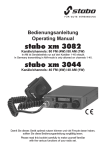
stabo xm 3001e
Art.-Nr. 30074
Bedienungsanleitung
Operating instructions
Manuel d'utilisation
Instrukcja obslugi
Damit Sie dieses Gerät optimal nutzen können
und viel Freude daran haben,
sollten Sie diese Bedienungsanleitung sorgfältig lesen.
Please read this booklet carefully to make yourself familiar
with the various functions of your radio set.
Pour être en mesure dutiliser cet appareil de façon optimale et
pour en trouver du plaisir, nous vous recommandons de lire ce
mode demploi avec le plus grand soin.
stabo xm 3001e.
1
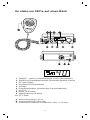
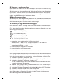
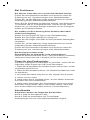
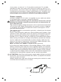
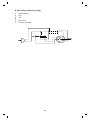
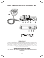
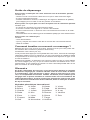
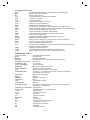
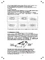
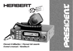
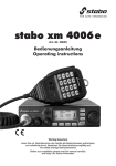
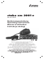
Ihr stabo xm 3001e auf einen Blick
HI-CUT
F
CH19
TX
VOL
OFF
TX
S/RF
xm 3001e
2 5 7 9
OFF OFF OFF
SQ
RF GAIN
M
S/RF
2 5 7 9
1
2
3
4
5
6
7
8
9
10
ON/OFF - Volume (Lautstärkeregler mit Ein-/Ausschalter)
SQUELCH (Rauschsperre)/ASC (Automatic Squelch Control)
RF Gain Regler
Kanalwahl mit Drehschalter
Anzeige
Programmschalter (Auswahl des Frequenzbandes)
HI-CUT
Kanal 19 Schalter
Mikrofonbuchse (6-polig)
PTT-Taste
A Stromversorgung (13,2 V)
B Antennenanschluß (SO-239)
C Anschluß für externen Lautsprecher (8W, Æ 3,5 mm)
2
Willkommen in der faszinierenden Welt des CB-Funks und
herzlichen Glückwunsch zu Ihrem CB-Funkgerät stabo xm 3001e.
Sie haben sich damit für ein komfortables Spitzengerät entschieden,
das über zahlreiche Zusatzfunktionen verfügt und sich sowohl im
Auto als auch als Feststation von zu Hause aus einsetzen läßt.
Weitere Kennzeichen sind einfache Bedienbarkeit und robuster
Aufbau.
Bitte lesen Sie diese Bedienungsanleitung sorgfältig durch, damit
Sie alle Möglichkeiten Ihres stabo xm 3001e optimal nutzen
können. Beachten Sie besonders die Hinweise zum Anschluß
und zur Installation. Und nun viel Spaß und viele schöne FunkKontakte mit Ihrem stabo xm 3001e!
Hinweise
CE-Kennzeichnung
Dieses Gerät erfüllt die Anforderungen der R&TTE-Direktive und
ist daher mit dem CE-Zeichen versehen. Das stabo xm 3001e
erfüllt die Standards EN 300433 und EN 301489 zur elektromagnetischen Verträglichkeit. Die Bestimmungen zur elektrischen
Sicherheit werden ebenfalls eingehalten.
Sicherheitshinweise
Herzschrittmacher
Jedes Funkgerät strahlt beim Senden elektromagnetische Wellen
aus, die bei anderen Geräten zu Störungen führen können. Ob
Störungen auftreten oder nicht, hängt jedoch von vielen Faktoren,
wie Sendeleistung, Frequenz, Modulationsart und nicht zuletzt
von der Störfestigkeit der anderen Geräte ab, um nur einige dieser
Faktoren zu nennen.
In den letzten Jahren ist besonders die Gefährdung von Personen
mit Herzschrittmachern durch Radiowellen in den Blickpunkt der
Öffentlichkeit gerückt. Moderne Herzschrittmacher werden in der
Regel nicht durch ein sachgemäß betriebenes CB-Funkgerät
beeinträchtigt. Sollten Sie jedoch einen Herzschrittmacher tragen,
so empfehlen wir Ihnen, Ihren Arzt zu fragen, welchen Abstand
Sie zur Sendeantenne einhalten müssen, um eine Gefährdung
definitiv auszuschließen. Vermeiden Sie jedoch auf jeden Fall,
eine Antenne im Sendebetrieb zu berühren.
Funkbetrieb während der Fahrt
Während Handies in fahrenden Kraftfahrzeugen nur noch mit einer
Freisprecheinrichtung benutzt werden dürfen, sieht die StVO
ausdrücklich eine Ausnahme für Funkgeräte, und damit auch für
CB-Funkgeräte, vor. Sie sollten aber zu Ihrer eigenen Sicherheit
Ihr Gerät nur dann benutzen, wenn die Verkehrslage dies erlaubt.
3
Vorschriften
Nutzungsbedingungen
Die R&TTE-Direktive hat seit 2001 alle früheren nationalen Zulassungsbestimmungen in der EU ersetzt; dennoch gelten für die
Nutzung des Frequenzspektrums zum Teil unterschiedliche nationale Regelungen.
In D ist der CB-Funk anmelde- und gebührenfrei. Dieses Gerät
darf in Deutschland mit den Programmierungen d (in AM darf nur
auf den Kanälen 1-40 gesendet werden) und EU betrieben werden.
Mit der Programmierung EU darf das Gerät in vielen Ländern
anmelde- und gebührenfrei genutzt werden (u.a. in D, F, NL, P),
einige Staaten verlangen dagegen eine Anmeldung ( z.B. B, CH).
In manchen Ländern (z.B. A) dürfen AM-Geräte nicht benutzt
werden.
Mit der Programmierung E dürfen Sie das Gerät in Spanien, mit
der Einstellung P in Polen benutzen.
Unsere Bitte: Erkundigen Sie sich bei den entsprechenden
Behörden und nehmen Sie die Vorschriften in den jeweiligen
Ländern ernst! Sie riskieren sonst evtl. eine empfindliche Strafe.
Für einige Länder genügt die Circulation Card, die Sie bei CBClubs oder in Deutschland auch bei der Bundesnetz-agentur
(www.bundesnetzagentur.de) (Canisiusstraße 21, 55122 Mainz,
Telefon 06131-18-0) erhalten können.
Einbauvorschriften
Seit einiger Zeit legen die Automobilhersteller fest, an welchen
Stellen im bzw. am KFz Funkgeräte sowie deren Antennen montiert
werden.
Dies geschieht zu Ihrem Schutz, einmal vor zu hohen Feldstärken
im Inneren des Fahrzeugs, zum anderen, um Fehlfunktionen der
Fahrzeugelektronik durch Einstrahlung zu vermeiden. Sie sollten
sich auf jeden Fall an diese Vorschriften halten, da anderenfalls
die Betriebserlaubnis für Ihr Fahrzeug erlöschen kann.
Fragen Sie daher bei Ihrem Autohändler nach den entsprechenden Herstellervorschriften für Ihr Fahrzeugmodell.
4
Lieferumfang
Das stabo xm 3001e wird mit einem hochwertigen Handmikrofon
mit PTT-Taste und Befestigung sowie einem Montagebügel geliefert.
Das bereits angeschlossene Stromversorgungskabel ist mit einer
Kabelsicherung versehen.
Installation
Montage im Auto
a) Beachten Sie die Anweisungen Ihres KFZ-Herstellers.
b) Achten Sie darauf, daß sich alle Kabel und Verbindungsleitungen
ohne Probleme durch das Fahrzeug führen lassen. Kabel nicht in
der Nähe der Heizung führen!
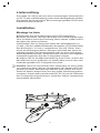
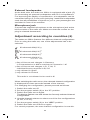
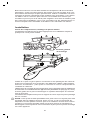
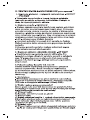
c) Befestigen Sie an geeigneter Stelle den Montagebügel (1)
(s. Abb. ) mit den selbstschneidenden Schrauben (2) (Durchmesser
des Bohrloches: 3,2 mm). Vergewissern Sie sich vorher, dass
durch die Befestigung keine Leitungen innerhalb des Autos beschädigt werden! Der Montagebügel sollte an einer passenden
Stelle angebracht werden, die einen festen, sicheren und möglichst
erschütterungsfreien Sitz des Funkgerätes erlaubt.
d) Wählen Sie für die Mikrofonhalterung einen Platz, an dem Sie
das Mikrofon immer griffbereit zur Hand haben und an dem sein
Verbindungskabel zum Funkgerät nicht stört.
Hinweis: Wenn für den Einbau des Funkgerätes so wenig Platz
zur Verfügung steht, daß der Lautsprecher (am Boden des Funkgerätes) in seiner Abstrahlung behindert wird, sollten Sie einen
externen Mobil-Lautsprecher aus dem stabo Zubehörprogramm
montieren. Dieser wird an die Buchse EXT.SP (C) auf der Rückseite
des Funkgerätes angeschlossen, wobei der interne Lautsprecher
automatisch abschaltet.
5
Anschluss der Antenne
Wahl der Antenne:
Auch im CB-Funk gilt: je besser die Antenne, desto grösser die
Reichweite der Station.
Treffen Sie die entsprechende Wahl nach den folgenden Empfehlungen!
Mobilantenne:
Es gibt abgestimmte und abstimmbare Antennen.
Abgestimmte Antennen sollten nur auf einer großen Metallunterfläche montiert werden, beispielsweise auf dem Wagendach oder
auf dem Kofferraumdeckel.
Sorgen Sie hierbei für eine kurze Verbindung nach Masse.
Wenn Sie für die Antenne ein Loch in die Karosserie bohren, muß
hierzu das Blech plan geschmirgelt werden, damit Befestigungsschraube und Dichtung gut sitzen!
Führen Sie das Koaxialkabel ohne Knicke und nicht über scharfe
Stellen (ansonsten: Kurzschluß-Gefahr!).
Befestigen Sie das Antennenkabel am Anschluß (B).
Feststations-Antenne:
Mit einer Feststations-Antenne erreichen Sie mit Ihrem Funkgerät
die maximale Reichweite. Bei Außenantennen müssen Sie unbedingt die einschlägigen VDE-Bestimmungen (Blitzschutz!), der
Statik und des Baurechtes beachten! Am besten,Sie lassen die
Antennenanlage in diesem Fall von einem Fachmann montieren!
Im stabo-Zubehörprogramm finden Sie eine Auswahl auch von
Feststations-Antennen.
Anpassen der Antenne
Senden Sie auf keinen Fall ohne Antenne, da das zur
Zerstörung des Gerätes führt.
Anpassung der Antenne bedeutet, dass Ihre Antenne auf den
Ausgangswiderstand des Senders, nämlich 50W, angepasst wird.
Der tatsächliche Wellenwiderstand der Antenne hängt nicht nur
von ihrer Länge, sondern auch von der Umgebung ab, in der sie
montiert ist. Daher kann der Hersteller nur eine grob abgestimmte
Antenne liefern. Sie wird in der Regel so gebaut, dass immer
genügend Spielraum für einen Abgleich auf die bestehenden
Verhältnisse bleibt. In der Praxis bedeutet das, dass eine neue
Antenne meist zu lang ist.
Zur Anpassung schleifen Sie zwischen dem stabo xm 3001e und
der Antenne eine VSWR-Messbrücke (z.B. President TOS-1, ArtNr. 50004) ein und verkürzen oder verlängern die Antenne nach
den Angaben des Herstellers so, dass das VSWR auf Ihrem Lieblingskanal oder einem der mittleren Kanäle möglichst klein wird.
Sie sollten auf jeden Fall einen Wert von 1:1,5 erreichen. Es hat
allerdings bei Mobilbetrieb wenig Sinn, unbedingt einen Wert
von 1:1 einstellen zu wollen, da andere Umgebungen, Veränderungen im Kabel etc. diesen Wert ohnehin wieder verändern
6
können. Sie sind jedoch gut beraten, die Anpassung regelmäßig
zu überprüfen, da ein schlechter Wert auf Probleme mit Steckern
und Kabel hinweist.
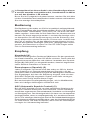
Stromversorgung
Ihr Funkgerät wird mit einer Gleichspannung von max. 13,2 Volt
versorgt. Es ist mit einem Verpolungsschutz ausgestattet.
Vergewissern Sie sich trotzdem vorher der richtigen Polarität!
Eine Verpolung führt zur Zerstörung Ihres CB-Funkgerätes.
Die Versorgungsspannung beträgt nominal 13,2 V und darf 15 V
auf keinen Fall überschreiten. Im Sendefall fließen dann etwa
1,7 A; bei voller Lautstärke bis zu 0,8 A und bei geschlossener
Rauschsperre etwa 0,5 A.
Der Minuspol liegt auf Masse (= Chassis), wie bei praktisch allen
modernen Autos.
Prüfen Sie vor dem Anschluß die Polarität und die Spannung: bei
älteren Wagen kann auch der Pluspol auf Masse liegen, während
bei einigen Nutzfahrzeugen die Bordspannung nicht 12V, sondern
24V beträgt. Fragen Sie im Zweifelsfall Ihre Fachwerkstatt!
Nachdem Sie sich hinsichtlich Spannung und Polarität versichert
haben, gehen Sie wie folgt vor:
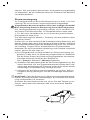
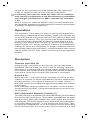
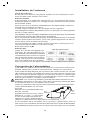
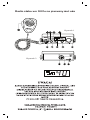
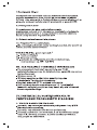
a) Ihr Funkgerät wird mit einem Kabel zur Stromversorgung (A)
geliefert, in das eine 2 A Sicherung eingeschleift ist. Schließen
Sie die freien Enden des Stromversorgungskabels mit entsprechenden Klemmen direkt an der Batterie an:
Rot = Pluspol, Schwarz = Minuspol (Masse).
b) Schließen Sie das Kabel direkt an der Fahrzeugbatterie an. Bei
einem Anschluß z.B. am Zigarettenanzünder würde das Funkgerät nach Ausschalten der Zündung sonst nicht mit der hierfür
notwendigen Pufferspannung versorgt werden.
c) Verlegen Sie das Stromversorgungkabel so im Auto, daß es
möglichst wenig Störungen von der Zündanlage aufnehmen
kann.
ACHTUNG: Falls die Sicherung im Stromversorgungskabel durchbrennt: a) Ursache finden und beseitigen, b) nur durch eine Sicherung mit ebenfalls 2 A ersetzen!
Schalten Sie das Gerät immer aus, bevor Sie das Fahrzeug verlassen, damit Sie beim nächsten Mal nicht eine leere Batterie
vorfinden.
zum Anlasser
7
Masse
zum
chassis
Externer Lautsprecher
Das stabo xm 3001e ist auf der Rückseite mit einem Anschluss (C)
für einen externen Lautsprecher mit 8 W Impedanz ausgerüstet.
Sie können zur Verbesserung der Wiedergabe einen Lautsprecher
mit einem 3,5mm-Mono-Klinkenstecker anschließen. Montieren
Sie den Lautsprecher so, dass er bei einem möglichen Unfall Sie
oder Ihre Mitfahrer nicht verletzen kann.
Mikrofonanschluss
Schließen Sie das mitgelieferte Mikrofon an dem Mikrofonanschluss
links auf der Vorderseite des Gerätes an. Achten Sie darauf, dass
die Aussparung am Stecker nach unten zeigt.
Länderprogrammierung (6)
Die stabo xm 3001e verfügt über vier verschiedene Kanalkonfigurationen.
Für eine der folgenden Konfigurationen müssen Sie sich vor der
Nutzung entscheiden.
80 Kanäle AM(1 W ) 1)
40 Kanäle AM(1 W ) 2)
40 Kanäle AM(4 W ) 3)
40 Kanäle AM(4 W ) 4)
mit einem Trägerversatz von -5 KHz
1) anmelde-
und gebührenfrei in Deutschland
das Senden in AM ist nur auf den Kanälen 1-40 erlaubt
2) anmelde- und gebührenfrei in D, F, NL, P
anmeldepflichtig in B, CH
3) ausschließlich in Spanien erlaubt
4) ausschließlich in Polen erlaubt
In A darf dieses Gerät nicht betrieben werden !
Die ausgewählte Kanalkonfiguration wird Ihnen beim Einschalten
des Gerätes für drei Sekunden anstelle des Kanals angezeigt.
Um die Konfiguration zu wechseln, gehen Sie bitte wie folgt vor.
1. Schalten Sie das Funkgerät aus.
2. Schieben Sie den Programm-Schalter (6) in die F Position.
3. Schalten Sie das Funkgerät wieder ein.
In der Kanalanzeige wird jetzt die bisher benutzte Kanalkonfiguration blinkend angezeigt.
4. Wählen Sie jetzt mit dem Kanalschalter eine der vier Konfigurationen (d, EU, E oder PL) aus.
5. Schieben Sie den Programm-Schalter (6) in die OFF Position.
6. Schalten Sie das Gerät aus und wieder ein.
Zur Kontrolle wird jetzt die neue Kanalkonfiguration für die nächsten
drei Sekunden angezeigt. Danach ist das Gerät mit der neuen
Kanalkonfiguration betriebsbereit.
8
In Deutschland ist dieses Gerät in den Kanalkonfigurationen
d und EU anmelde-und gebührenfrei, Sendebetrieb in AM ist
nur auf den Kanälen 1- 40 erlaubt.
Bevor Sie Ihr Funkgerät im Ausland nutzen, machen Sie sich bitte
mit den Vorschriften der betreffenden Länder vertraut und beachten
Sie eine etwaige Anmeldepflicht.
Bedienung
Die Bedienung des stabo xm 3001e ist praktisch selbsterklärend.
Nach Fertigstellung aller Anschlüsse schalten Sie Ihr CB-Funkgerät
an dem linken Drehschalter (OFF/VOL) ein, der auch die Lautstärke reguliert. Jetzt sollte für drei Sekunden der Ländercode und
danach ein Kanal angezeigt werden. Leuchtet die Anzeige nicht,
so überprüfen Sie die Stromversorgung und die Sicherung. Aus
dem Lautsprecher müsste Rauschen zu hören sein. Ist dies nicht
der Fall, so prüfen Sie, ob das Mikrofon angeschlossen ist und
drehen den mittleren Drehregler (SQL/ASC ) entgegen dem Uhrzeigersinn, bis Rauschen zu hören ist. Der RF-Gain Regler sollte
sich im Rechtsanschlag befinden.
Empfang
Kanalwahl (4)
Mit dem rechten großen Drehknopf (4) können Sie den gewünschten Kanal einstellen, auf dem Sie hören möchten. Dann sollte bei
angeschlossenem Mikrofon und mittlerer Lautstärke der SquelchRegler (2) (SQL/ASC) so eingestellt werden, dass bei angeschlossener Antenne Rauschen zu hören ist.
Rauschsperre (Squelch) (2)
Jedes Funkgerät, und somit auch das stabo xm 3001e, besitzt
eine Schaltung zur Rauschunterdrückung (Squelch), die bei
fehlendem oder zu schwachem Signal die Wiedergabe unterdrückt.
Der Signalpegel, bei dem die Schaltung eingreift, wird mit dem
SQL/ASC-Regler (2) eingestellt. Drehen nach links verringert,
Drehen nach rechts erhöht diesen Pegel.
Bei wechselnden Empfangsbedingungen, wie im Mobilbetrieb,
kann ein häufiges Nachregeln erforderlich sein.
ASC (Automatic Squelch Control) (2)
Bei der ASC handelt es sich um eine patentierte Schaltung der
Groupe President Electronics SA Frankreich. Diese Schaltung
wertet den sogenannten Rauschabstand (Verhältnis von Nutzsignal
zu Störsignal) aus. Das Nutzsignal wird nur dann zum Lautsprecher
durchgeschaltet, wenn es empfangswürdig, d.h. annähernd rauschfrei ist. Ein ständiges Nachregeln wie bei der feldstärkeabhängigen
Rauschsperrenschaltung entfällt daher, was der Verkehrssicherheit
zu Gute kommt. Die ASC ist aktiviert, wenn sich der Rauschsperrenregler im Linksanschlag befindet.
9
RF-Gain Regler (3)
In der Modulationsart AM kann es zu Verzerrungen kommen, wenn
der Signalpegel (S-Wert) zu hoch ist. Benutzen Sie dann den RFGain Regler, um die Verstärkung zu verringern.
HI-CUT:
Mit diesem Schalter können Sie die hohen Töne absenken und
damit auch das Rauschen bei schwachen Empfangsignalen reduzieren.
Kanal 19 (8)
Direktschaltung auf Kanal 19. Durch Hochschieben des Schalters
auf die Einstellung CH19 schaltet das Gerät direkt auf Kanal 19.
Durch Herunterschieben des Schalters befinden Sie sich wieder
auf dem zuvor eingestellten Kanal.
Signalstärke (5)
Links neben der Kanalanzeige sehen Sie eine Balkenanzeige. Sie
zeigt bei Empfang die Signalstärke in S-Stufen an. Es werden die
S-Werte 2,5,7 und 9 angezeigt. Werte über S9, 9+10 und mehr
werden als S9 angezeigt. Es handelt sich dann um sehr starke
Signale, meist von einer benachbarten Station.
Senden
Um zu senden, müssen Sie nur die PTT-Taste (push to talk-Taste)
an der linken Seite des Mikrofons drücken und bei gedrückter
Taste mit normaler Lautstärke in das Mikrofon sprechen. Sprechen
Sie nicht zu laut, damit Ihre Stimme bei der Gegenstation natürlich
klingt. Am besten probieren Sie es einmal aus und lassen sich
einen Modulationsbericht geben. Denken Sie aber bitte daran,
dass Sie ohne angeschlossene und angepasste Antenne nicht
senden sollten, da sonst Ihr Funkgerät dabei Schaden nimmt.
Warten Sie einen Moment, bevor Sie zu senden beginnen um zu
hören, ob der Kanal frei ist, damit Sie nicht mit einer anderen
Station doppeln. Denken Sie auch daran, dass der Sender eine
gewisse Zeit braucht, bis er hochfährt, also nicht gleich losreden,
sondern besser eine Sekunde warten.
Leistungsanzeige
Wenn Sie die PTT -Taste am Mikrofon drücken,wird in der Balkenanzeige anstelle des S-Wertes die relative Ausgangsleistung des
Senders angezeigt.
10
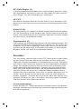
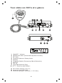
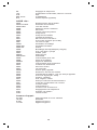
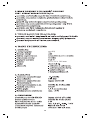
Belegung der Mikrofonbuchse (sechspolig)
1
2
3
4
5
6
Modulation
RX
TX
Masse
Stromversorgung
11
Technische Daten
Allgemein
Kanäle:
Betriebsart:
Frequenzbereich:
Antennen-Impedanz:
Versorgungsspannung:
Abmessungen (BxHxT):
Gewicht:
Lieferumfang:
Filter:
Sendeteil
Frequenzstabilität:
Sendeleistung:
Nebenwellen:
Frequenzgang:
Nachbarkanalleistung:
Mikrofon-Empfindlichkeit:
Stromverbrauch:
Klirrfaktor:
40 (80)
AM
26,565 MHz bis 27,405 MHz
50 Ohm
13,2 V Gleichspannung
116 x 36 x 168 mm
ca. 0,8 kg
Funkgerät
Handmikrofon Elektret
mit Halterung
Montagebügel
Montagematerial
integrierte ANL
(automatischer Störbegrenzer)
+/- 300 Hz
1 / 4 W AM
unter 4 nW (-54 dBm)
300 Hz - 3 kHz in AM
unter 20 µW
10 mV
1,5 A max.
1,8 %
Empfangsteil
Empfindlichkeit (20 dB SINAD): 0,7 µV - 110 dBm (AM)
Frequenzgang:
300 Hz - 3 kHz AM
Nachbarkanal-Selektion:
60 dB
NF-Ausgangsleistung:
5W
Squelch-Empfindlichkeit:
minimum 0.2 µV - 120 dBm
maximum 1 mV - 47 dBm
Spiegelfrequenzunterdrückung: 60 dB
ZF-Unterdrückung:
70 dB
Stromverbrauch:
500 mA nominal
12
Bei Problemen
Sie können nicht oder nur in schlechter Qualität senden:
Prüfen Sie das Stehwellenverhältnis Ihrer Antenne sowie die
Zuleitung auf evtl. Unterbrechungen oder Wackelkontakte!
Prüfen Sie, ob das Mikrofon richtig angeschlossen ist und die
Verbindung keinen Wackelkontakt aufweist!
Wenn Sie die Sendetaste am Mikrofon drücken, muß die Anzeige
TX leuchten und Ihr Funkgerät senden. Lassen Sie die Taste
wieder los, so muß diese Anzeige erlöschen und Ihr Funkgerät
wieder auf Empfang schalten.
Sie erhalten auf Ihre Sendung keine Antwort oder haben
schlechten Empfang:
Stellen Sie den Regler RF-Gain in den Rechtsanschlag.
Stellen Sie den Regler SQUELCH richtig ein!
Stellen Sie den Regler VOLUME auf eine passende WiedergabeLautstärke.
Prüfen Sie, ob das Mikrofon richtig angeschlossen ist und die
Verbindung keinen Wackelkontakt aufweist!
Prüfen Sie das Stehwellenverhältnis Ihrer Antenne sowie die
Zuleitung auf evtl. Unterbrechungen oder Wackelkontakte!
Die Anzeigen leuchten nicht:
Überprüfen Sie Ihr Netzgerät: Ist es eingeschaltet?
Haben Sie die Anschlüsse für Plus (= ROT) und Minus (=Schwarz)
vertauscht? Wechseln Sie in diesem Fall die Anschlüsse.
Tipps für den Funkverkehr:
Um einen ungestörten Funkverkehr zu genießen, sollten Sie die
folgenden sechs Regeln des CB-Funks beherzigen:
1. Nach dem Einschalten des Gerätes immer zuerst hören, ob der
eingestellte Kanal frei ist.
2. Dazu die Rauschsperre öffnen, um schwächere Stationen nicht
zu überhören.
3. Nur wenn der Kanal völlig frei ist, den eigenen Anruf starten.
4. Immer nur kurz rufen.
5. Nach jedem Anruf sorgfältig hören, ob eine Station antwortet.
Erst dann den Anruf wiederholen.
6. Nach jedem Durchgang der Gegenstation immer erst einige
Sekunden Pause lassen, bevor man selber spricht, damit sich
auch andere Stationen melden können ("Umschaltpause").
Anrufkanäle
Empfohlen werden die folgenden Anrufkanäle:
Kanal 4 (AM) als Anrufkanal in AM,
Kanal 9 (AM) als Notrufkanal und Truckerkanal
Abweichungen hiervon sind selbstverständlich möglich.
13
Bei schlechten Verbindugen oder starken Störungen ist es häufig
problematisch, schwer zu verstehende Worte wie Eigennamen
und Städtenamen fehlerlos zu übermitteln.
Hier hilft das Internationale Buchstabieralphabet weiter, das auch
im Luftverkehr (ICAO) und bei der NATO eingesetzt wird:
Internationales Phonetisches Alphabet
A Alpha
B Bravo
C Charlie
D Delta
E Echo
F Foxtrott
G Golf
H Hotel
I India
J Juliett
K Kilo
L Lima
M Mike
N November
O Oscar
P Papa
Q Quebec
R Romeo
S Sierra
T Tango
U Uniform
V
W
X
Y
Z
Victor
Whiskey
X-ray
Yankee
Zulu
Beurteilung der Empfangsqualität
Um dem jeweiligen Gesprächspartner eindeutig sagen zu können,
wie stark und klar man ihn empfängt, verwendet man die Ziffern
des R/S-Codes. Dabei steht der R-Wert für die Verständlichkeit
("Lesbarkeit") und der S-Wert ("Santiago") für die Empfangs- bzw.
Lautstärke der Gegenstation.
Die beiden Buchstaben R und S stehen als Abkürzung für die
englischsprachigen Bezeichnungen "readability" (= Lesbarkeit)
und "signal strength" (= Signalstärke).
S = Signalstärke
R/S-Code
1 kaum hörbar
2 sehr schwach hörbar
3 schwach hörbar
4 ausreichend hörbar
5 ziemlich gut hörbar
6 gut hörbar
7 mäßig stark hörbar
8 stark hörbar
9 sehr stark hörbar
R = Lesbarkeit
1
2
3
4
5
nicht lesbar, unverständlich
zeit-oder teilweise lesbar
schwer lesbar
lesbar, verständlich
gut lesbar
Abkürzungen
Auch der CB-Funk kennt eine "Fachsprache", die mit vielen
Fachwörtern durchsetzt ist, die z.B.aus dem Amateurfunk und
dem professionellen Funkverkehr entlehnt sind.
Sie dienen zumeist der schnellen und eindeutigen Nachrichtenübermittlung auch in solchen Fällen, in denen die Übertragung
schwierig bzw. gestört ist. Nachfolgend eine Auflistung gebräuchlicher Abkürzungen und ihre Bedeutung, wie sie meistens im CBFunk verwendet werden:
14
Break:
Cheerio:
CQ:
CL:
DX:
Fading:
Hl:
Mike:
Müll:
Negativ:
OK:
Roger:
Skip:
Standby:
Stereo:
TVI:
Moment bitte, bitte warten, möchte mitsprechen
Auf Wiederhören
allgemeiner Anruf
Ende des Funkverkehrs, Station wird abgeschaltet
Funkverbindung über große Entfernung
Signal schwankt
Ich lache
Mikrofon
Störungen
habe nicht verstanden, nein
verstanden, richtig, in Ordnung
Ich habe verstanden, alles einwandfrei empfangen
Funkrufname
Auf Empfang bleiben
Zwei Stationen senden gleichzeitig
Fernsehstörungen
Q-Gruppen
Beim CB-Funkverkehr werden sehr häufig Abkürzungen verwendet.
Viele von ihnen wurden aus dem international verbindlichen QCode übernommen, der auch im Seefunk oder im Amateurfunk
Anwendung findet. Mit diesen Drei-Buchstaben-Kürzeln lassen
sich schnell Informationen vermitteln. Da besonders "CB-Neulinge"
mitunter diese Abkürzungen nicht kennen, haben wir die
gebräuchlichsten einmal zusammengestellt und ihre Bedeutung
im CB-Funk erläutert:
QRA:
QRG:
QRL:
QRM:
QRN:
QRP:
QRT:
QRU:
QRV:
QRX:
QRZ:
QSB:
QSL:
QSO:
QSP:
QST:
QSY:
QTH:
Mein Stationsname ist...
Frequenz, Betriebskanal
Beschäftigung, Arbeitsplatz
Störung durch andere Stationen
Atmosphärische Störungen
Arbeiten mit geringer Leistung
Ende des Funkverkehrs
Es liegen keine weiteren Nachrichten mehr vor.
Sende- und empfangsbereit
Unterbrechung des Funkverkehrs, Pause, bitte warten
Sie werden gerufen, Anruf von einer bestimmten Station
Schwankungen der Feldstärke, Schwund, Fading
Empfangsbestätigung
Funkverbindung, Gespräch über Funk
Vermittlung zweier Stationen für eine dritte
Durchsage an alle
Frequenzwechsel, Kanalwechsel
Standort
15
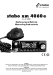
Your stabo xm 3001e at a glance
HI-CUT
F
CH19
TX
VOL
OFF
TX
S/RF
2 5 7 9
OFF OFF OFF
SQ
RF GAIN
M
S/RF
2 5 7 9
1
2
3
4
5
6
7
8
9
10
ON/OFF - Volume
SQUELCH/ASC (Automatic Squelch Control)
RF Gain
Channel Selector Rotary Knob
Display
Program Switch (Frequency Band Selection)
HI-CUT
CH 19
6-pin Microphone Plug
PTT "Push-to-talk" Button
A DC Power Supply (13.2 V)
B Antenna Jack (SO-239)
C External Speaker Jack (8W, Æ 3.5 mm)
16
xm 3001e
Welcome to the fascinating world of CB radio and congratulations
on having purchased the CB radio set stabo xm 3001e. You have
made a decision in favor of a comfortable high-end radio set
providing numerous extra functions a radio set which can either
be used for mobile operation in your car or as stationary radio set
at home. This radio set is characterized by easy-to-use functions
and a rugged construction.
Please read this manual carefully to be able to use all functions
of your stabo xm 3001e in the best possible way. Please consider
above all the notes on connection and installation. Enjoy your
stabo xm 3001e and the radio contacts established thanks to this
radio set!
Notes
CE marking
This radio set meets the requirements of the R&TTE Directive and
is thus provided with the CE mark. The stabo xm 3001e satisfies
the standards EN 300433 and EN 301489 on electromagnetic
compatibility (EMC). Furthermore, the regulations on the electric
safety are observed as well.
Safety warnings
Pacemaker
Each radio set emits electromagnetic waves during transmission
which could lead to malfunctions of different devices. However,
the occurrence of such malfunctions depends on many factors,
as the transmitting power, the frequency, the type of modulation
and, not least, on the interference immunity of the other devices
just to mention some of these factors.
During the last few years, the endangering of persons having a
pacemaker due to radio waves has become one focal point of
public interest. An appropriately operated CB radio set normally
does not harm contemporary pacemakers. However, if you have
a pacemaker, we recommend you to consult your doctor for the
distance which is to be kept to the transmitting antenna for definitely
avoiding any endangerment. In any case you should avoid to touch
the antenna in transmit mode.
Radio operation while driving
Meanwhile mobile phones may only be used in running motor
vehicles using a handsfree equipment. In Germany, an express
exception to this rule is provided for radio sets and consequently
also for CB radio sets in the Motor Vehicle Traffic Regulations.
However, for your own safety, you should only use your radio set
if the traffic situation permits.
17
Regulations
Use policies
Within the different countries of the European Union, partially
different regulations for using CB radio sets apply. Since 2001,
the R&TTE Directive has replaced all former national conditions
of admission in the European Union. Nevertheless, partially different
national regulations apply to the usage of the frequency spectrum.
In D CB operation is free of licence and free of charge. This
radio can be operated in Germany with the programming d
(transmission in AM is only allowed on CH 1- 40) and EU.
In the frequency band EU the radio can be operated in several
countries free of licence and free of charge (D, F, NL,P), in some
countries a licence is requested (e.g. B, CH), in others the use of
AM radios is forbidden (e.g. A).
With the frequency band E you may use this radio in Spain, with
PL in Poland.
Our urgent request: Prior to using your radio set, please take
the compulsory registration in the above mentioned countries
seriously! If you are met with an adjustment subject to registration
and you are not able to present any registration, you risk to be
punished with a severe penalty. The Circulation Card, which is
available at the CB radio clubs or at the Bundesnetzagentur
(www.bundesnetzagentur.de) (Canisiusstraße 21, 55122 Mainz,
Telefon 06131-18-0) , is sufficient in other countries.
Instructions for installation
For some time, the automobile manufacturers have specified the
positions in and on the motor vehicles at which the radio sets and
its antennas may be mounted.
On the one hand, this is done to protect you from excessive field
intensities inside your motor vehicle, on the other hand to avoid
malfunctions of the electronic system in the car due to radiation.
In any case, you should observe these specifications, since the
type approval of your vehicle can expire otherwise.
Thus, contact your automobile dealer for the corresponding
manufacturer specifications belonging to your car model.
18
Scope of delivery
The radio set stabo xm 3001e comes with a high-quality hand
microphone with push-to-talk button and attachment as well as
with a mounting device.
The already connected power supply cable is equipped with a
cable retention.
Installation
Installation in the motor vehicle
a) Please consider the instructions of your automobile manufacturer.
b) Make sure that all cables and connecting lines are laid in the
motor vehicle without any problems such that the vehicle operation
is not impaired. Do not install the cables near the heating system!
c) For installing your radio set at the appropriate position (see
figure), use the mounting device (1) and the tapping screws (2)
(drill hole diameter: 3.2 mm). Prior to drilling, make sure not to
damage any cables of the electric system in the car ! The mounting
device should be installed at an appropriate place providing a rigid,
reliable and almost vibrationless positioning of the radio set.
d) Choose a place for the microphone attachment such that the
microphone is always within reach. Remember that its microphone
cord must not interfere with the control elements of the vehicle.
Note: If the space for installing the radio set is so very restricted
that the loudspeaker radiation (at the bottom of the radio set) is
impaired, we recommend you to install an external mobile speaker
available as stabo accessory. This speaker is connected to the
EXT.SP jack (C) situated at the back side of the radio set. When
connecting the external speaker, the internal loudspeaker is automatically deactivated.
19
Antenna connection
Choosing your antenna:
The following applies to CB radio as well: The better the antenna
quality, the greater the range of the radio set.
Make the appropriate choice according to the following recommendations!
Mobile antenna:
A distinction is made between tuned and tuneable antennas.
Tuned antennas should only be mounted on a great metallic surface, as for example on the roof of the vehicle or the trunk lid,
assuring a short connection to ground.
For an antenna which must be fixed by drilling a hole into the car
body, the body sheet must be thoroughly smoothed in order to
assure a reliable positioning of the fixing screws and the sealing
washer!
Be careful not to bend the coaxial cable or to damage it otherwise
by positioning it on sharp edges (for avoiding the risk of shortcircuits!).
Connect the antenna cable to jack (B).
Antenna for stationary radio sets:
When using a stationary antenna, the maximum range of your
radio set is achieved. For outside antennas, the relevant regulations
of the German VDE (Association of German Electrotechnical
Engineers) (with regard to lightning protection!), of constructural
statics and of the building code have to be considered by all means!
In this case, we recommend you to have the antenna system
installed by an expert!
Please refer to the stabo accessories for a comprehensive range
of stationary antennas.
Adapting the antenna
You should not transmit without antenna under any circumstances, since this would result in a destruction of the radio
set.
Adapting the antenna means that your antenna is adjusted to the
output resistance of the transmitter, i.e. to 50 W.
The actual characteristic antenna impedance depends on its length
and on its environment of installation. For this reason, the manufacturer can only provide you with a roughly tuned antenna. Normally it is designed such that there is always enough scope left
for adjusting it to the given conditions. In practical operation, this
means that a new antenna is usually too long.
For adapting the antenna, a VSWR resistance bridge (e.g. President
TOS-1, article no. 50004) is connected into the circuit between
the stabo xm 3001e and the antenna and the antenna is shortened
or elongated according to the manufacturers information such
that the VSWR on your preferred channel or one of the median
channels is as small as possible.
20
In any case, a value of 1:1.5 should be achieved. For mobile
operation,it does not make much sense to adjust a value of 1:1
by all means, since this value can always be modified again due
to different environments, cable modifications etc. However, we
recommend you to check the adjustment regularly, because an
unfavourable value points to connector and cable problems.
Power supply
A direct voltage of 13.2 volts is supplied to your radio set which
is equipped with a reverse voltage protection.
However, before switching it on, check the device for correct
polarity! A polarity reversal would result in a destruction of
your CB radio set.
The nominal supply voltage amounts to 13.2 V and must not exceed
15 V in any case. When transmitting, an electric current of approx.
1.7 A flows, up to 0.8 A at maximum volume and approx. 0.5 A
with activated squelch.
The negative pole is connected to ground (= chassis) as for almost
all modern cars.
Prior to connecting the radio set, check polarity and voltage: If the
vehicle is older, the positive pole can also be connected to ground.
Some commercial vehicles are supplied with a voltage of 24 V
instead of 12 V. When in doubt, contact your specialized car dealer!
After having checked the voltage and polarity, proceed as follows:
a) Your radio set is provided with a power supply cable (A) into
which a 2 A fuse is connected. Connect the cable directly to the
battery using the corresponding terminals:
Red = positive pole, black = negative pole (ground).
b) Connect the cable directly to the storage battery of the vehicle.
When connecting the radio set to the cigarette lighter, for example,
the radio set is not supplied anymore with the necessary back-up
voltage after having switched off the ignition system of the vehicle.
c) Lay the power supply cable in the car such that the interferences
resulting from the ignition system are as small as possible.
ATTENTION: If the fuse in the power supply cable is blown, proceed
as follows: a) Find and eliminate the cause, b) replace the blown
fuse by a new 2 A fuse!
Always switch the radio set off before leaving the vehicle in order
to avoid that the battery is run down.
.
to the starter
21
ground
to chassis
External loudspeaker
At the back side, the stabo xm 3001e is equipped with a jack (C)
for connecting an external loudspeaker with an 8 W impedance.
For improving the fidelity of reproduction, a loudspeaker can be
connected using a 3.5 mm mono jack plug. Install the loudspeaker
such that all possibilities of injuries to you or your passengers are
excluded in case of an accident.
Microphone jack
Connect the supplied microphone to the microphone jack at the
left front side of the radio set. Make sure that the recess on the
plug is oriented downwards.
Adjustment according to countries (6)
The stabo xm 3001e features four different channel configurations.
Prior to using the radio set, one of the adjustments has to be
selected.
80 channels AM (1 W ) 1)
40 channels AM (1 W ) 2)
40 channels AM (4 W ) 3)
40 channels AM (4 W ) 4)
carrier offset -5 KHz
1) free
of licence and charges in Germany
in D transmission in AM is restricted to channels 1- 40
2) free of licence and charges in D , F, NL, P
individual licence required in B, CH
3) only allowed in Spain
4) only allowed in Poland
This radio is not allowed to be used in A!
When switching the radio set on, the selected channel configuration
is displayed for three seconds instead of the channel.
For changing the configuration, please proceed as follows.
1. Switch the radio set off.
2. Set the program switch (6) to the F position.
3. Switch the radio set on again.
The display flashes now and shows the formerly selected channel
configuration.
4. Use the channel selector to select one of the four configurations
(d, EU, E or PL).
5. Set the program switch (6) to the OFF position.
6. Switch the radio set off and on again.
For control purposes, the new channel configuration is now dis22
played for the next three seconds. Afterwards, the radio set is
ready for operation with the new channel configuration.
In Germany, the radio set stabo xm 3001e can be operated
with channel configuration d and EU without any registration
and charges, transmission in AM is restricted to channels
1- 40.
Before using your radio set abroad, make yourself familiar with
the applicable regulations for the respective countries and consider
a possible compulsory registration.
Operation
The operation of the stabo xm 3001e is almost self-explanatory.
After having established all connections, switch your CB radio set
on by using the left rotary knob (ON/OFF/VOL) which is also used
for setting the volume. First, the country code should be displayed
for three seconds, afterwards a channel should appear in the
display. If the display does not light up, please check the power
supply and the fuse. A noise should be audible in the loudspeaker.
Failing this, check the microphone for proper connection and turn
the median rotary knob (SQL/ASC ) counterclockwise until a noise
can be heard. The RF Gain control should be set to the rightmost
position.
Reception
Channel selection (4)
Using the big rotary knob on the right (4), you can adjust the
requested channel which you wish to use for hearing. With the
microphone connected and the volume control adjusted to a medium volume, the squelch control (2) (SQL/ASC) should be adjusted
such that a noise can be heard if the antenna is connected.
Squelch (2)
Each radio set and consequently the stabo xm 3001e as well
features a function for noise suppression (squelch) suppressing
the reproduction, if the signal is lacking or too weak. Use the
SQL/ASC control (2) to adjust the signal level at which this function
is activated.
With constantly varying conditions of reception, as for example
during mobile operation, a frequent adjustment of this level can
be necessary.
ASC (Automatic Squelch Control) (2)
The ASC function is a patented function elaborated by the President
Electronics SA France group. This function evaluates the so-called
signal-to-noise ratio (ratio between the useful signal and the interfering signal). The useful signal is only forwarded to the loudspeaker,
if it is worth being received, i.e. it is almost free from noise. Thus,
a permanent readjustment, as for the squelch function depending
on the field strength, is not necessary. This is of benefit to a safe
23
participation in the street traffic when driving. The ASC function is
activated if the squelch control is set to the leftmost position.
RF Gain control (3)
With the AM type of modulation, the signal can be distorted, if the
signal level (S value) is too high. In this case, use the RF Gain
control to reduce the amplification.
HI-CUT (7):
Cuts out high frequency interference. Its use depends on reception
conditions.
To activate this function, move the switch to HI-CUT position. Move
the same switch to OFF position to deactivate.
Channel 19 (8)
Channel 19 is automatically selected when you activate this switch.
To activate this function, move the switch to CH19 position, and
to return to the previous channel move the same switch to OFF
position.
Signal intensity (5)
A bar display can be seen to the left next to the channel display.
During reception, this display shows the signal strength in S-grades.
The S-grades 2, 5, 7 and 9 are indicated. Values above S9, 9+10
and even higher are indicated as S9. In this case, the received
signals are very intensive and are transmitted by an adjacent radio
station.
Transmission
For transmitting, you just have to press the push-to talk button
on the left side of your microphone and to speak with normal voice
level into the microphone. Dont speak to loud such that the sound
of your voice is natural for your radio contact partner. We recommend you to test this and to ask for a modulation report afterwards.
However, please keep in mind that you should not transmit without
connected and adapted antenna, since this would dammage your
radio set.
Before starting the transmission, wait for a moment to make sure
that the channel is free and that there is no doubling with a
different radio station. Furthermore, please note that the radio
station need a certain time to carry out its start-up sequency. Thus,
you should better wait for a second before speaking.
Power display
When pressing the push-to-talk button on your microphone, the
bar display shows the relative transmitting power instead of the
S-value.
24
6-pin microphone plug
1
2
3
4
5
6
Modulation
RX
TX
Ground
Power Supply
25
Technical characteristics
General
Channels:
Modulation mode:
Frequency ranges:
Antenna impedance:
Power supply:
Dimensions (WxHxD):
Weight:
Accessories supplied:
40 (80)
AM
from 26.565 MHz to 27.405 MHz
50 Ohms
13.2 V
116 x 36 x 168 mm
0.8 kg
Electret microphone with
support,
mounting device,
screws.
ANL (Automatic Noise Limiter)
built-in
Filter:
Transmission
Frequency stability:
+/- 300 Hz
Transmission power:
1 / 4 W AM
Transmission interference:
inferior to 4 nW (- 54 dBm)
Frequecy response:
300 Hz to 3 KHz in AM
Emitted power in the adj. chann.: inferior to 20 µW
Microphone sensitivity:
10 mV
Power consumption:
1.5 A max.
Modulated signal distortion:
1.8 %
Reception
Maxi. sensitivity at 20 dB sinad:
Frequency response:
Adjacent channel selectivity:
Maximum audio power:
Squelch sensitivity:
0.7 µV - 110 dBm (AM)
300 Hz to 3 kHz in AM
60 dB
5W
minimum 0.2 µV - 120 dBm
maximum 1 mV - 47 dBm
Frequency image rejection rate: 60 dB
Intermediate frequency rej. rate: 70 dB
Power consumption:
500 mA nominal
Trouble shooting
Your CB radio does not transmit or your transmission power
is poor:
Check that the antenna is correctly connected and that the SWR
is properly adjusted.
Check that the microphone is properly plugged in.
With the "push-to-talk" switch activated, the display flashes. Release
the "push-totalk" switch, then press it again to reactivate the transmission mode.
26
Your CB radio does not receive or reception is poor:
Set the RF Gain control to the rightmost position.
Check that the squelch level is properly adjusted.
Check that the volume is set to a comfortable listening level.
Check that the microphone is properly plugged in.
Check that the antenna is correctly connected and that the SWR
is properly adjusted.
Check that you are using the same modulation mode (AM) as your
contact partner.
Your CB does not light up:
Check the power supply.
Check the connection wiring.
Check the fuse.
How to transmit or receive a message:
Now that you have read the manual, make sure that your CB radio
set is ready for use (i.e. check that your antenna is connected).
Choose your channel (19, 27).
Press the "push-to-talk" button and announce your message
"Attention stations, transmission testing" which will allow you to
check the clearness and the power of your signal. Release the
switch and wait for a reply. You should receive a reply like, "Strong
and clear".
If you use a calling channel (19, 27) and you have established
communication with someone, it is common practice to choose
another available channel so as not to block the calling channel.
Glossary
Below you will find some of the most frequently used CB radio
expressions. Remember this is meant for fun and that you are by
no means obliged to use them. In an emergency, you should be
as clear as possible.
International phonetic alphabet:
A Alpha
B Bravo
C Charlie
D Delta
E Echo
F Foxtrott
G Golf
H Hotel
I India
J Juliett
K Kilo
L Lima
M Mike
N November
O Oscar
P Papa
Q Quebec
R Romeo
S Sierra
T Tango
U Uniform
27
V
W
X
Y
Z
Victor
Whiskey
X-ray
Yankee
Zulu
Technical vocabulary:
AM
CB
CH
CW
DX
DW
FM
GMT
HF
LF
LSB
RX
SSB
SWR
SWL
SW
TX
UHF
USB
VHF
Amplitude Modulation
Citizens Band
Channel
Continuous Wave
Long Distance Liaison
Dual Watch
Frequency Modulation
Greenwich Meantime
High Frequency
Low Frequency
Lower Side Band
Receiver
Single Side Band
Standing Wave Ratio
Short Wave Listening
Short Wave
CB Transceiver
Ultra High Frequency
Upper Side Band
Very High Frequency
CB Language:
Advertising
Back off
Basement
Base station
Bear
Bear bite
Bear cage
Big slab
Big 10-4
Bleeding
Flashing lights of police car
Slow down
Channel 1
A CB set in fixed location
Policeman
Speeding fine
Police station
Motorway
Absolutely
Signal from an adjacent channel
interfering with the transmission
Blocking the channel
Pressing the PTT switch without
talking
Blue boys
Police
Break
Used to ask permission to join a
conversation
Breaker
A CBer wishing to join a channel
Clean and green
Clear of police
Cleaner channel
Channel with less interference
Coming in loud and proud : Good reception
Doughnut
Tyre
Down and gone
Turning CB off
Down one
Go to a lower channel
Do you copy?
Understand?
DX
Long distance
Eighty eights
Love and kisses
Eye ball
CBers meeting together
Good buddy
Fellow CBer
Hammer
Accelerator
28
Handle
Harvey wall banger
How am I hitting you?
Keying the mike
CBers nickname
Dangerous driver
How are you receiving me?
Pressing the PTT switch without
talking
Kojac with a kodak
Police radar
Land line
Telephone
Lunch box
CB set
Man with a gun
Police radar
Mayday
SOS
Meat wagon
Ambulance
Midnight shopper
Thief
Modulation
Conversation
Negative copy
No reply
Over your shoulder
Right behind you
Part your hair
Behave yourself - police ahead
Pull your hammer back
Slow down
Rat race
Congested traffic
Rubberbander
New CBer
Sail boat fuel
Wind
Smokey dozing
Parked police car
Smokey with a camera
Police radar
Spaghetti bowl
Interchange
Stinger
Antenna
Turkey
Dumb CBer
Up one
Go up one channel
Wall to wall
All over/everywhere
What am I putting to you? Please give me an S-meter reading
29
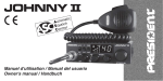
Votre stabo xm 3001e en un coup dil
HI-CUT
F
CH19
TX
VOL
xm 3001e
SQ
RF GAIN
M
OFF
TX
S/RF
2 5 7 9
OFF OFF OFF
S/RF
2 5 7 9
Attention!
Avant toute utilisation, prenez garde de ne jamais émettre sans
avoir branché lantenne (connecteur B situé sur la face arrière de
lappareil), ni réglé le TOS (Taux dOndes Stationnaires)! Sinon,
vous risquez de détruire lamplificateur de puissance, ce qui nest
pas couvert par la garantie.
Appareil multi-normes!
Voir fonction F page 34 et tableau des Normes Européennes
page 48 ff.
30
Bienvenue dans le monde des émetteurs-récepteurs CB de la dernière
génération. Cette nouvelle gamme de postes vous fait accéder à la communication électronique la plus performante. Grâce à lutilisation de technologies de pointe garantissant des qualités sans précédent, votre stabo
xm 3001e est un nouveau jalon dans la convivialité et la solution par
excellence pour le pro de la CB le plus exigeant. Pour tirer le meilleur parti
de toutes ses possibilités, nous vous conseillons de lire attentivement ce
mode demploi avant dinstaller et dutiliser votre CB stabo xm 3001e.
Installation
Choix de lemplacement, montage du poste mobile
Choisissez lemplacement le plus approprié à une utilisation simple et
pratique de votre poste mobile.
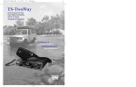
xm 3001 e
Schéma général
de montage
Veillez à ce quil ne gêne pas le conducteur ni les passagers du véhicule.
Prévoyez le passage et la protection des différents câbles, (alimentation,
antenne, accessoires...) afin quils ne viennent en aucun cas perturber la
conduite du véhicule.
Utilisez pour le montage le berceau (1) livré avec lappareil, fixez-le solidement
à laide des vis autotaraudeuses (2) fournies (diamètre de perçage 3,2 mm).
Prenez garde de ne pas endommager le système électrique du véhicule
lors du perçage.
Choisissez un emplacement pour le support du micro et prévoyez le passage
de son cordon.
NOTA: Votre poste mobile possédant une prise micro en façade peut être
encastré dans le tableau de bord. Dans ce cas, il est recommandé dy
adjoindre un haut-parleur externe pour une meilleure écoute des communications (connecteur EXT.SP situé sur la face arrière de lappareil: C.
Renseignez-vous auprès de votre revendeur le plus proche pour le montage
sur votre appareil.
31
Installation de lantenne
Choix de lantenne
En CB, plus une antenne est grande, meilleur est son rendement. Votre
Point Conseil saura orienter votre choix.
Antenne mobile
Il faut linstaller à un endroit du véhicule où il y a un maximum de surface
métallique (plan de masse), en séloignant des montants du pare-brise et
de la lunette arrière.
Dans le cas où une antenne radiotéléphone est déjà installée, lantenne
CB doit être au-dessus de celle-ci.
Il existe 2 types dantennes : les préréglées et les réglables.
Les préréglées sutilisent de préférence avec un bon plan de masse (pavillon
de toit ou malle arrière).
Les réglables offrent une plage dutilisation beaucoup plus large et permettent
de tirer parti de plans de masse moins importants.
Pour une antenne à fixation par perçage, il est nécessaire davoir un excellent
contact antenne/plan de masse ; pour cela, grattez légèrement la tôle au
niveau de la vis et de létoile de serrage.
Lors du passage du câble coaxial, prenez garde de ne pas le pincer ou
lécraser (risque de rupture ou de court-circuit).
Branchez lantenne (B).
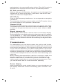
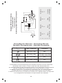
Antenne fixe
Lobe de rayonnement
Veillez à ce quelle soit dégagée au
maximum. En cas de fixation sur un
mât, il faudra éventuellement haubaner
conformément aux normes en vigueur
(se renseigner auprès dun professionnel). Les antennes et accessoires
que nous distribuons sont spécialement conçus pour un rendement optimal de chaque appareil de la gamme.
Connexion de lalimentation
Votre stabo xm 3001e est muni dune protection contre les inversions de
polarité. Néanmoins, avant tout branchement, vérifiez vos connexions.
Votre poste doit être alimenté par une source de courant continu de 12 Volts
(A). A lheure actuelle, la plupart des voitures et des camions fonctionnent
avec une mise à la masse négative. On peut sen assurer en vérifiant que
la borne (-) de la batterie soit bien connectée au bloc moteur ou au châssis.
Dans le cas contraire, consultez votre revendeur.
Attention: Les camions possèdent généralement deux batteries et une
installation électrique en 24 Volts. Il sera donc nécessaire dintercaler dans
le circuit électrique un convertisseur 24/12 Volts.
Toutes les opérations de branchement suivantes doivent être effectuées
cordon dalimentation non raccordé
au poste :
Assurez-vous que lalimentation soit
Relié
Vers
bien de 12 Volts.
au
démarreur
châssis
Repérez les bornes (+) et (-) de la
batterie (+ = rouge, - = noir). Dans
le cas où il serait nécessaire de
rallonger le cordon dalimentation,
utilisez un câble de section équivalente ou supérieure.
Il est nécessaire de se connecter sur un (+) et un (-) permanents. Pour ce
faire nous vous conseillons de brancher directement le cordon dalimentation
sur la batterie (le branchement sur le cordon de lauto-radio ou sur dautres
32
parties du circuit électrique pouvant dans certains cas favoriser la réception
de signaux parasites).
Branchez le fil rouge (+) à la borne positive de la batterie et le fil noir (-) à
la borne négative de la batterie.
Branchez le cordon dalimentation au poste.
Attention: Ne jamais remplacer le fusible dorigine (2 A) par un modèle
dune valeur différente !
Opérations de base à effectuer avant la première
utilisation, sans passer en émission (cest à dire
sans appuyer sur la pédale du micro):
Branchez le micro,
Vérifiez le branchement de lantenne,
Mise en marche de lappareil : tourner le bouton VOLUME dans le sens
des aiguilles dune montre.
Tournez le bouton SQUELCH au minimum (dans le sens inverse des aiguilles
dune montre). Réglez le bouton VOLUME à un niveau convenable.
Amenez le poste sur le canal 20 à laide du rotacteur situé sur la face avant.
Réglage du tos (Taux dondes stationnaires):
Attention: Opération à effectuer impérativement lors de la première utilisation
de lappareil ou lors dun changement dantenne. Ce réglage doit être fait
dans un endroit dégagé, à lair libre.
*Réglage avec TOS-Mètre externe (p.ex. PRESIDENT TOS-1, art.-no. 50004)
Branchement du Tos-mètre :
- branchez le Tos-mètre entre le poste et lantenne, le plus près possible
du poste (utilisez pour cela un câble de 40 cm maximum).
Réglage du Tos :
- amenez le poste sur le canal 20,
- positionnez le commutateur du Tos-mètre en position CAL ou FWD
- appuyez sur la pédale du micro pour passer en émission,
à laide du bouton de calibrage,
- amenez laiguille sur lindex
- basculez le commutateur en position SWR (lecture de la valeur du TOS).
La valeur lue sur le vu-mètre doit être très proche de 1. Dans le cas
contraire, réajustez votre antenne jusquà obtention dune valeur aussi
proche que possible de 1 (une valeur de TOS comprise entre 1 et 1,8 est
acceptable),
- il est nécessaire de recalibrer le Tos-mètre, entre chaque opération de
réglage de lantenne.
Remarque: Afin déviter les pertes et atténuations dans les câbles de
connexion entre la radio et ses accessoires, nous recommandons une
longueur de câble inférieure à 3 m.
Maintenant, votre poste est prêt à fonctionner.
Utilisation
1) marche/arret - volume:
Pour allumer votre poste, tourner le bouton (1) dans le sens des aiguilles
dune montre.
Pour augmenter le volume sonore, continuer à tourner ce bouton dans le
sens des aiguilles dune montre.
2) ASC (Automatic Squelch Control)/SQUELCH :
Cette fonction permet de supprimer les bruits de fond indésirables en
labsence de communication. Le squelch ne joue ni sur le volume sonore
ni sur la puissance démission, mais il permet daméliorer considérablement
le confort découte.
33
ASC: squelch a reglage automatique
Brevet mondial, exclusivité PRESIDENT Électronics SA/France.
Aucun réglage manuel répétitif et optimisation permanente entre la sensibilité
et le confort découte lorsque lASC est actif (à fond en sens inverse des
aiguilles dune montre). Elle est débrayable par rotation du bouton (2) dans
le sens des aiguilles dune montre. Dans ce cas le réglage du squelch
redevient manuel.
Squelch manuel
Tournez le bouton du squelch dans le sens des aiguilles dune montre
jusquau point exact où tout bruit de fond disparaît. Cest un réglage à
effectuer avec précision, car mis en position maximum dans le sens des
aiguilles dune montre, seuls les signaux les plus forts peuvent être perçus.
3) RF Gain:
Réglage de la sensibilité en réception. Position maximum dans le cas de
réception de communications longue distance. Vous pouvez diminuer le
RF GAIN, pour éviter des distorsions, lorsque linterlocuteur est proche.
Réduisez le gain en réception dans le cas dune communication rapprochée
avec un correspondant non équipé dun RF POWER.
La position normale de cette fonction se situe au maximum dans le sens
des aiguilles dune montre.
4) Sélecteur de canaux: rotateur en façade
La rotation de ce bouton vous permet de sélectionner le canal (de 1 à 40)
démission ou de réception.
5) Afficheur:
Il permet de visualiser lensemble des fonctions :
Le BARGRAPH visualise le niveau de réception et le niveau de puissance
émise. Le voyant TX sallume lors du passage en émission.
6) Sélection de bande de fréquences
Les bandes de fréquences doivent être choisies selon le pays où vous
utilisez votre appareil. Nutilisez en aucun cas une configuration différente.
Certains pays nécessitent une licence dutilisation.
a) Éteignez lappareil.
b) Placez linterrupteur F/OFF sur la position F.
c) Allumez lappareil.
d) Tournez le bouton des canaux et sélectionnez la bande de fréquence
désirée (voir tableau page 48 ff).
e) Placer linterrupteur F/OFF sur la position OFF.
f) Éteignez à nouveau lappareil puis rallumez-le pour valider votre choix.
7) HI-CUT :
Élimination des parasites haute fréquence. À utiliser en fonction des conditions
de réception.
Un positionnement du commutateur sur HI-CUT active la fonction. Un
positionnement sur OFF désactive la fonction.
8) CH 19
Le canal 19 sera automatiquement sélectionné par lintermédiaire de cette
commande.Un positionnement du commutateur sur CH19 active le canal
19. Un nouveau positionnement sur OFF vous ramène au canal précédent.
9) Prise micro 6 broches
Elle se situe en façade de votre appareil et facilite ainsi son intégration à
bord de votre véhicule. Voir schéma de branchement en page 50.
34
10) Pedale demission du micro
Appuyer pour parler et relacher pour recevoir un message.
A) Alimentation (13,2 V)
B) Prise dantenne (SO-239)
C) Prise pour haut-parleur exterieur (8 W, Ø 3,5 mm)
Caractéristiques techniques
Générales
Canaux:
Mode de modulation:
Gamme de fréquence:
Impédance dantenne:
Tension dalimentation:
Dimensions (en mm):
Poids:
Accessoires inclus:
40 (80)
AM
de 26,565 MHz à 27,405 MHz
50 ohms
13.2 V
116 (L) x 36 (H) x 168 (P)
0,8 kg
1 microphone Electret et son support,
1 berceau, vis de fixation
ANL (Automatic Noise Limiter) intégré
Filtre:
Émission
Tolérance de fréquence:
Puissance porteuse:
Émissions parasites:
Réponse en fréquence:
Puissance émise dans le canal adj.:
Sensibilité du microphone:
Consommation:
Distorsion maxi. du signal modulé:
Réception
Sensibilité maxi à 20 dB sinad:
Réponse en fréquence:
Sélectivité du canal adj.:
Puissance audio maxi:
Sensibilité du squelch:
Taux de réj. fréq. image:
Taux de réjection fréq. interméd.:
Consommation:
+/- 300 Hz
1/4 W AM
inférieure à 4 nW (- 54 dBm)
300 Hz à 3 kHz en AM
inférieure à 20 µW
10 mV
1,5 A
1,8 %
0,7 µV - 110 dBm
300 Hz à 3 kHz en AM
60 dB
5W
mini 0.2 µV - 120 dBm
maxi 1 mV - 47 dBm
60 dB
70 dB
500 mA nominal
35
Guide de dépannage
Votre poste német pas ou votre émission est de mauvaise qualité.
Vérifiez que:
- lantenne soit correctement branchée et que le TOS soit bien réglé.
- le micro soit bien branché.
- Pédale démission activée, laffichage TX clignote. Relâchez la pédale,
puis réappuyez sur celle-ci afin de passer en émission.
Votre poste ne reçoit pas ou votre réception est de mauvaise qualité.
Vérifiez que:
- le niveau du squelch soit correctement réglé.
- le bouton Volume soit réglé à un niveau convenable.
- le micro soit branché. Lantenne soit correctement branchée et le TOS
bien réglé.
- vous êtes bien sur le même type de modulation (AM) que votre interlocuteur.
Votre poste ne sallume pas.
Vérifiez:
- votre alimentation.
- quil ny ait pas dinversion des fils au niveau de votre branchement.
- létat du fusible.
Comment émettre ou recevoir un message ?
Maintenant que vous avez lu la notice, assurez-vous que votre poste est
en situation de fonctionner (antenne branchée).
Choisissez votre canal (19, 27).
Vous pouvez alors appuyer sur la pédale de votre micro, et lancer le message
«Attention stations pour un essai TX» ce qui vous permet de vérifier la clarté
et la puissance de votre signal et devra entraîner une réponse du type «Fort
et clair la station».
Relâchez la pédale, et attendez une réponse. Dans le cas où vous utilisez
un canal dappel (19, 27), et que la communication est établie avec votre
interlocuteur, il est dusage de choisir un autre canal disponible afin de ne
pas encombrer le canal dappel.
Glossaire
Au fil de lutilisation de votre TX, vous découvrirez parfois un langage
particulier employé par certains cibistes. Afin de vous aider à mieux
le comprendre, vous trouverez ci-aprés dans le glossaire et le code
«Q.» un récapitulatif des termes utilisés. Toutefois, il est évident quun
langage clair et précis facilitera le contact entre tous les amateurs de
radiocommunication. Cest la raison pour laquelle les termes que vous
lirez ci-dessous sont donnés à titre indicatif, mais ne sont pas à utiliser
de façon formelle.
Alphabet phonétique international
A Alpha
B Bravo
C Charlie
D Delta
E Echo
F Foxtrott
G Golf
H Hotel
I India
J Juliett
K Kilo
L Lima
M Mike
N November
O Oscar
P Papa
Q Quebec
R Romeo
S Sierra
T Tango
U Uniform
36
V
W
X
Y
Z
Victor
Whiskey
X-ray
Yankee
Zulu
Langage technique:
AM:
Amplitude Modulation (modulation damplitude)
BLU:
Bande latérale unique
BF:
Basse fréquence
CB:
Citizen Band (canaux banalisés)
CH:
Channel (canal)
CQ:
Appel général
CW:
Continuous waves (morse)
DX:
Liaison longue distance
DW:
Dual watch (double veille)
FM:
Frequency modulation (modulation de fréquence)
GMT:
Greenwich Meantime (heure du méridien de Greenwich)
GP:
Ground plane (antenne verticale)
HF:
High Frequency (haute fréquence)
LSB:
Low Side Band (bande latérale inférieure)
RX:
Receiver (récepteur)
SSB:
Single Side Band (Bande latérale unique)
SWR:
Standing Waves Ratio
SWL:
Short waves listening (écoute en ondes courtes)
SW:
Short waves (ondes courtes)
TOS:
Taux dondes stationnaires
TX:
Transceiver. Désigne un poste émetteur-récepteur CB.
Indique aussi lémission.
UHF:
Ultra-haute fréquence
USB:
Up Side Band (bande latérale supérieure)
VHF:
Very high Frequency (très haute fréquence)
LANGAGE CB :
ALPHA LIMA:
BAC:
BASE:
BREAK:
CANNE A PÊCHE:
CHEERIO BY:
CITY NUMBER:
COPIER:
FIXE MOBILE:
FB:
INFERIEURS:
Amplificateur linéaire
Poste CB
Station de base
Demande de sintercaler, sinterrompre
antenne
Au revoir
Code postal
Écouter, capter, recevoir
Station mobile arrêtée
Fine business (bon, excellent)
Canaux en-dessous des 40 canaux autorisés
(interdits en France)
MAYDAY:
Appel de détresse
MIKE:
Micro
MOBILE:
Station mobile
NÉGATIF:
Non
OM:
Opérateur radio
SUCETTE:
Micro
SUPÉRIEURS:
Canaux au-dessus des 40 canaux autorisés
(interdits en France)
TANTE VICTORINE: Télévision
TONTON:
Amplificateur de puissance
TPH:
Téléphone
TVI:
Interférences TV
VISU:
Se voir
VX:
Vieux copains
WHISKY:
Watts
WX:
Le temps
XYL:
Lépouse de lopérateur
YL:
Opératrice radio
51:
Poignée de mains
73:
Amitiés
88:
Grosses bises
37
99:
144:
318:
600 ohms:
813:
CODE «Q» :
QRA:
QRA Familial:
QRA PRO:
QRB:
QRD:
QRE:
QRG:
QRH:
QRI:
QRJ:
QRK:
QRL:
QRM:
QRM DX:
QRM 22:
QRN:
QRO:
QRP:
QRPP:
QRPPette:
QRQ:
QRR:
QRRR:
QRS:
QRT:
QRU:
QRV:
QRW:
QRX:
QRZ:
QSA:
QSB:
QSJ:
QSK:
QSL:
QSO:
QSP:
QSX:
QSY:
QTH:
QTR:
Canaux dappel:
27 AM:
19 AM:
9 AM:
11 FM:
Dégager la fréquence
Polarisation horizontale, aller se coucher
Pipi
le téléphone
Gastro liquide (apéritif)
Emplacement de la station
Domicile de la station
Lieu de travail
Distance entre 2 stations
Direction
Heure darrivée prévue
Fréquence
Fréquence instable
Tonalité démission
Me recevez-vous bien?
Force des signaux (R1 à R5)
Je suis occupé
Parasites, brouillage
Parasites lointains
Police
Brouillage atmosphérique (orages)
Fort, très bien, sympa
Faible, petit
Petit garçon
Petite fille
Transmettez plus vite
Nom de la station
Appel de détresse
Transmettez plus lentement
Cessez les émissions
Plus rien à dire
Je suis prêt
Avisez que jappelle
Restez en écoute un instant
Indicatif de la station : par qui suis-je appelé?
Force de signal (S1 à S9)
Fading, variation
Prix, argent, valeur
Dois-je continuer la transmission?
Carte de confirmation de contact
Contact radio
Transmettre à...
Voulez-vous écouter sur...
Dégagement de fréquence
Position de station
Heure locale
appel général en zone urbaine
Routiers
Appel durgence
Appel durgence
38
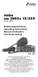
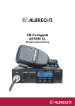
Radio stabo xm 3001e na pierwszy rzut oka
Rysunek 1
HI-CUT
F
CH19
TX
VOL
OFF
SQ
M
Rysunek 2
TX
S/RF
2 5 7 9
39
S/RF
2 5 7 9
OFF OFF OFF
RF GAIN
xm 3001e
stabo xm 3001e
stabo
stabo xm 3001e
stabo xm 3001e.
xm 3001 e
40
41
stabo
stabo xm 3001e
42
4.
stabo
43
1
50
44
2
45
(80)
116 x 36 x 168 mm
46
A
B
C
D
E
F
G
Alpha
Bravo
Charlie
Delta
Echo
Foxtrott
Golf
H Hotel
I India
J Juliett
K Kilo
L Lima
M Mike
N November
O
P
Q
R
S
T
U
Oscar
Papa
Quebec
Romeo
Sierra
Tango
Uniform
47
V Victor
W Whiskey
X X-ray
Y Yankee
Z Zulu
48
1
2
3
4
5
6
7
8
9
10
11
12
13
14
15
16
17
18
19
20
Kanal
Channel
N° du canal
Kana
26,965
26,975
26,985
27,005
27,015
27,025
27,035
27,055
27,065
27,075
27,085
27,105
27,115
27,125
27,135
27,155
27,165
27,175
27,185
27,205
Frequenzen
Frequency
Fréquences
Cz stotliwo
21
22
23
24
25
26
27
28
29
30
31
32
33
34
35
36
37
38
39
40
Kanal
Channel
N° du canal
Kana
27,215
27,225
27,255
27,235
27,245
27,265
27,275
27,285
27,295
27,305
27,315
27,325
27,335
27,345
27,355
27,365
27,375
27,385
27,395
27,405
Frequenzen
Frequency
Fréquences
Cz stotliwo
41
42
43
44
45
46
47
48
49
50
51
52
53
54
55
56
57
58
59
60
Kanal
Channel
N° du canal
Kana
26,565
26,575
26,585
26,595
26,605
26,615
26,625
26,635
26,645
26,655
26,665
26,675
26,685
26,695
26,705
26,715
26,725
26,735
26,745
26,755
Frequenzen
Frequency
Fréquences
Cz stotliwo
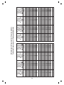
CB-Kanäle und ihre Frequenzen für d / Frequency table for d
Tableau des Fréquences pour d / Tabela czestotliwosci dla d
61
62
63
64
65
66
67
68
69
70
71
72
73
74
75
76
77
78
79
80
Kanal
Channel
N° du canal
Kana
26,765
26,775
26,785
26,795
26,805
26,815
26,825
26,835
26,845
26,855
26,865
26,875
26,885
26,895
26,905
26,915
26,925
26,935
26,945
26,955
Frequenzen
Frequency
Fréquences
Cz stotliwo
49
Frequenzen
Frequency
Fréquences
Cz stotliwo
26,965 MHz
26,975 MHz
26,985 MHz
27,005 MHz
27,015 MHz
27,025 MHz
27,035 MHz
27,055 MHz
27,065 MHz
27,075 MHz
27,085 MHz
27,105 MHz
27,115 MHz
27,125 MHz
27,135 MHz
27,155 MHz
27,165 MHz
27,175 MHz
27,185 MHz
27,205 MHz
Kanal
Channel
N° du canal
Kana
1
2
3
4
5
6
7
8
9
10
11
12
13
14
15
16
17
18
19
20
21
22
23
24
25
26
27
28
29
30
31
32
33
34
35
36
37
38
39
40
Kanal
Channel
N° du canal
Kana
27,215 MHz
27,225 MHz
27,255 MHz
27,235 MHz
27,245 MHz
27,265 MHz
27,275 MHz
27,285 MHz
27,295 MHz
27,305 MHz
27,315 MHz
27,325 MHz
27,335 MHz
27,345 MHz
27,355 MHz
27,365 MHz
27,375 MHz
27,385 MHz
27,395 MHz
27,405 MHz
Frequenzen
Frequency
Fréquences
Cz stotliwo
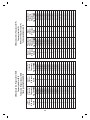
CB-Kanäle und ihre Frequenzen für EU /E
Frequency table for EU /E
Tableau des Fréquences pour EU /E
Tabela czestotliwosci dla EU /E
Frequenzen
Frequency
Fréquences
Cz stotliwo
26,960 MHz
26,970 MHz
26,980 MHz
27,000 MHz
27,010 MHz
27,020 MHz
27,030 MHz
27,050 MHz
27,060 MHz
27,070 MHz
27,080 MHz
27,100 MHz
27,110 MHz
27,120 MHz
27,130 MHz
27,150 MHz
27,160 MHz
27,170 MHz
27,180 MHz
27,200 MHz
Kanal
Channel
N° du canal
Kana
1
2
3
4
5
6
7
8
9
10
11
12
13
14
15
16
17
18
19
20
21
22
23
24
25
26
27
28
29
30
31
32
33
34
35
36
37
38
39
40
Kanal
Channel
N° du canal
Kana
27,210 MHz
27,220 MHz
27,250 MHz
27,230 MHz
27,240 MHz
27,260 MHz
27,270 MHz
27,280 MHz
27,290 MHz
27,300 MHz
27,310 MHz
27,320 MHz
27,330 MHz
27,340 MHz
27,350 MHz
27,360 MHz
27,370 MHz
27,380 MHz
27,390 MHz
27,400 MHz
Frequenzen
Frequency
Fréquences
Cz stotliwo
CB-Kanäle und ihre Frequenzen für PL
Frequency table for PL
Tableau des Fréquences pour PL
Tabela czestotliwosci dla PL
Zasilenie pr du
Alimentation
Stromversorgung
6
Power Supply
-
Uziemienie
Masse
-
5
Ground
-
Masse
4
RX
Modulación
TX
TX
TX
TX
3
RX
Modulation
RX
2
Modulation
Modulation
1
RX
Belegung der Mikrofonbuchse (6-polig)
6-pin microphone socket
Prise micro 6 broches
Oznakowanie gniazda mikrofonowego 6-cio pinowe
Europäische Normen - European Norms
Normes Européennes - Normas Europeas
Configuration
Code
AM Channel
Country
80 CH (1 W)
DE *
40 CH (1 W)
DE, BE, IE, NL,
PT, ES, CH, FR
40 CH (4 W)
ES
40 CH (4W) -5 KHz
PL
*In AM ist Sendebetrieb in Deutschland nur auf den Kanälen 1-40 erlaubt.
Freuenzband und Sendeleistung Ihres Gerätes müsssen mit den nationalen
Richtlinien des Landes, in dem es benutzt wird, übereinstimmen.
The frequenzy band and the transmission power of your transceiver must correspond
with the configuration authorized in the country where it is used.
La bande de fréquence et la puissance d'émission de votre appareil doivent
correspondre à la configuration autorisée dans la pays où il est utilisé.
La banda de frecuencias y la potencia de emisión de su aparato deben corresponder
a la configuración autorizada en el país donde él es utilizado.
50
Hersteller - Garantie
5 Jahre
GARANTIE
5 years warranty
Als Hersteller dieses Geräts gewähren wir, die
stabo Elektronik GmbH,
Münchewiese 16, 31137 Hildesheim/Deutschland
eine selbständige Garantie gegenüber dem Verbraucher.
Die Garantieleistung erstreckt sich auf die kostenlose Beseitigung
aller Fabrikations- und Materialfehler zum Zeitpunkt des Kaufs
dieses Geräts (Beschaffenheitsgarantie).
Die Garantie gilt nicht für:
- Transportschäden,
- den Betrieb mit Zubehör, das nicht durch stabo für den Betrieb
mit diesem Gerät freigegeben und entsprechend gekennzeichnet
wurde
- Sicherungen, Anzeigenleuchten und Halbleiter, die durch
fehlerhafte Bedienung beschädigt wurden,
- Geräte, die unbefugt geöffnet oder verändert wurden,
- Funktionen, die nicht in der Bedienungsanleitung beschrieben
sind,
- Fehler durch unsachgemäße Handhabung, mutwillige Beschädigung, mechanische Überbeanspruchung, übermäßige Hitze
oder Feuchtigkeitseinwirkung, ausgelaufene Batterien, falsche
Versorgungsspannung oder Blitzschlag,
- Verbrauchsmaterialien (Akkupacks, Batterien)
- Fracht- oder Transportkosten.
Gewährleistungsansprüche gegenüber dem Händler aufgrund des
Kaufvertrages bestehen gesondert neben diesen Garantiebestimmungen und werden hierdurch nicht eingeschränkt.
Dieser Garantie-Abschnitt ist nur gültig, wenn er vollständig
ausgefüllt und unterschrieben ist.
Geräte-Typ:________________________________
Geräte-Nummer(n):__________________________
Gekauft bei:
(Stempel oder genaue Anschrift des Händlers)
Kaufdatum:_____________________________
Unterschrift des Händlers:______________________________
53
Hochwertige elektronische
Geräte sind sehr komplex: kleine
Ursachen haben manchmal große
Wirkung! Viele Probleme lassen sich jedoch
schnell und unkompliziert am Telefon lösen.
Schicken Sie deshalb Ihr neues Gerät nicht gleich zurück,
STOP
sondern nutzen Sie die telefonische Beratung des stabo
Service-Teams. Unsere Techniker kennen sich mit
den Geräten sehr genau aus und stehen Ihnen
gerne mit praktischen Tipps und
kompetenten Ratschlägen
zur Seite.
Sie erreichen uns Mo. bis Fr. von 9 -12 Uhr.
Telefon 05121-762032
Halten Sie für das Gespräch das Gerät
und die Bedienungsanleitung bereit.
Irrtümer und Änderungen vorbehalten.
Errors and technical modifications reserved.
Sous réserve derreurs et de modifications.
B dy i zmieniony test jest mo liwy.
Copyright © 10 / 2009 stabo Elektronik GmbH
stabo Elektronik GmbH
Münchewiese 14 -16 . 31137 Hildesheim / Germany
Tel. +49 (0) 5121-76 20 - 0 . Fax: +49 (0) 5121- 51 29 79
Internet: www.stabo.de . E-Mail: [email protected]
1
UTZZ01371BZ(0)
Gibt es Schwierigkeiten,
das neue Gerät
in Betrieb zu nehmen?