1
stabo xm 5006 e
Art.-Nr. 30056
Bedienungsanleitung
Operating instructions
0341
Wichtig!
Lesen Sie vor Inbetriebnahme des Geräts alle Bedienhinweise aufmerksam und vollständig durch.
Bewahren Sie diese Anleitung sorgfältig auf, sie enthält wichtige Betriebshinweise.
Important!
Prior to using the device for the first time, carefully and completely read through all operating
instructions. Keep these operating instructions in a safe place; it contains important hints for
operating the device.
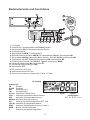
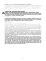
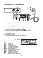
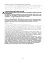
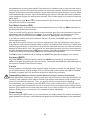
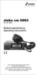
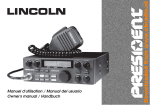
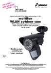
Bedienelemente und Anschlüsse
10
12
1
2
xm 5006e
4
1
2
3
4
5
6
7
8
9
10
11
12
3
5
6
7
8
9
10 11
LC-Display
Einsteller für Lautstärke VOL und Ein/Aus-Schalter
Rauschsperre SQ und Automatic Squelch Control
Frontlautsprecher
Speicherbetrieb MEM, Funktionstaste F
Modulationsart-Umschalter AM/FM, HF-Abschwächer LOCAL, Speicherplatz M1
Störaustaster NB/ANL (Automatic Noise Limiter), Suchlauf SCAN, Speicherplatz M2
Tiefpassfilter HI-CUT, Zweikanalüberwachung DW, Speicherplatz M3
Direktzugriff auf Kanäle 19/9 CH19/9, Tastatur-Quittungston BEEP
Kanalwahl CH aufwärts s und abwärts t
sechspolige Mikrofonbuchse (Mic)
Sprechtaste (PTT)
A DC-Anschluss 12/24 Volt
B Antennenanschluss 50 Ohm
C Anschluss für externen Lautsprecher 3 Watt, 4-8 Ohm
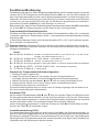
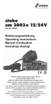
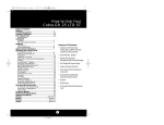
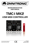
LC - Display
Anzeige für
TX
Senden
SCAN Suchlauf
AM
Modulationsart
FM
Modulationsart
HI-CUT aktiviertes Tiefpass-Filter
ASC
aktivierte automatische Rauschsperre
DW
aktivierte Zweikanalüberwachung
NB/ANL aktivierte Störunterdrückung
UK
Anzeige der Kanalkonfiguration MPT 1382
LOCAL aktivierter Eingangsabschwächer
EMG
aktivierter Direktzugriff auf Kanal 19 oder 9
MEM
Betrieb im Speichermodus
F
Änderung der Kanalkonfiguration
2
Kanal
Kanalkonfiguration
(EU, PL, d, EC, U, In)
Produktbeschreibung
Willkommen in der faszinierenden Welt des CB-Funks und herzlichen Glückwunsch zu Ihrem CBFunkgerät stabo xm 5006e. Sie haben sich damit für ein komfortables Spitzengerät entschieden,
das sich sowohl mobil im Auto als auch als Feststation von zu Hause aus einsetzen lässt, und
welches über zahlreiche Funktionen verfügt.
Funktionen
- 12/24 V Betrieb ohne Umschaltung
- energieeffizienter 24V-Betrieb ohne zusätzliche Wärmeentwicklung
- sechs umschaltbare Frequenztabellen
EU 40 Kanäle FM/4 Watt, 40 Kanäle AM/4 Watt
PL 40 Kanäle FM/4 Watt, 40 Kanäle AM/4 Watt mit -5 kHz Versatz
d
80 Kanäle FM/4 Watt, 40 Kanäle AM/4 Watt
EC 40 Kanäle FM/4 Watt
U 40 Kanäle AM/FM/4 Watt (CEPT) + 40 FM Kanäle/4 Watt (MPT 1382)
In 27 Kanäle FM/4 Watt, 27 Kanäle AM/4 Watt
- kontinuierliche Zweikanal-Überwachung, (D)ual (W)atch
- drei Speicherplätze (M1-M3) für Ihre Hauskanäle
- Speicherplatz-Suchlauf sowie Suchlauf über alle Kanäle (SCAN)
- Direktschaltung Kanäle 9/19 (CH19/9)
- schaltbare (N)oise (B)lanker und (A)utomatic (N)oise (L)imiter Schaltung
- schaltbares Tiefpass-Filter (HI-CUT)
- schaltbarer Tastatur-Quittungston (BEEP)
- schaltbarer HF-Abschwächer (LOCAL)
- Multifunktions-LC-Display mit Anzeige der Signalstärke (S-Wert), der relativen Sendeleistung
sowie der verschiedenen Betriebsmodi
- glasklare, durchdringende Modulation in FM und AM
Lieferumfang
CB-Funkgerät stabo xm 5006e
Montagebügel
Elektret-Mikrofon mit up/down-Funktion
Mikrofonhalterung
Bedienungsanleitung
3
Wichtige Informationen
Sicherheitshinweise
Trägern von Herzschrittmachern wird dringend empfohlen zunächst einen Arzt zu fragen, ob
grundsätzlich Bedenken gegen die Nutzung eines Funkgeräts bestehen bzw. welche Verhaltensregeln dabei zu beachten sind.
Berühren Sie auf keinen Fall während des Sendens die Antenne!
Machen Sie sich, bevor Sie das Gerät im Fahrzeug nutzen, unbedingt mit den Funktionen und
der Bedienung vertraut! Lassen Sie sich auf keinen Fall durch die Bedienung des Geräts oder
durch Funkgespräche vom Verkehrsgeschehen ablenken!
Senden Sie nie ohne angeschlossene Antenne!
Öffnen Sie nie das Gehäuse eines Funkgeräts oder des Zubehörs und führen Sie keine Änderungen
durch. Lassen Sie Reparaturen ausschließlich von qualifizierten Personen vornehmen.
Veränderungen oder Eingriffe am Funkgerät ziehen automatisch ein Erlöschen der Betriebserlaubnis
nach sich, es entfällt zudem Ihr Garantie-Anspruch!
Verhindern Sie, dass Kinder mit dem Funkgerät, Zubehörteilen oder dem Verpackungsmaterial
spielen.
Nutzen Sie das Gerät nicht, wenn Sie Schäden am Gehäuse oder an der Antenne entdecken:
setzen Sie sich mit einer Fachwerkstatt in Verbindung.
Schützen Sie Ihr Funkgerät und das Zubehör vor Nässe, Hitze, Staub und starken Erschütterungen.
Vermeiden Sie Betriebstemperaturen unter -10°C oder über +50°C.
Gesetzliche Vorgaben
Betrieb von CB-Funkgeräten: In Deutschland ist dieses Gerät in den Konfigurationen d, EU,
EC und In anmelde- und gebührenfrei zu nutzen. In anderen Ländern gelten jedoch ggf. abweichende
Bestimmungen: informieren Sie sich vor Nutzung des Geräts im Ausland über die aktuell geltenden
nationalen Vorschriften! Beachten Sie die entsprechenden Bestimmungen sowie eine etwaige
Anmeldepflicht Sie riskieren sonst empfindliche Bußgelder oder gar die Beschlagnahme Ihres
Funkgeräts!
Einbau eines Funkgeräts in ein KFZ: Bei fast allen Kraftfahrzeugen legt der Hersteller Einbauvorschriften für Funkgeräte und Antennen fest: erkundigen Sie sich deshalb bei Ihrem Autohändler
nach den entsprechenden Herstellervorschriften für Ihr Fahrzeugmodell. Beachten Sie beim
Einbau unbedingt diese Vorgaben, da sonst die Betriebserlaubnis für Ihr Fahrzeug erlöschen
kann!
Nutzung von Sprechfunk im Fahrzeug: Während der Fahrer eines Kraftfahrzeugs Mobiltelefone
nur mit einer Freisprecheinrichtung bzw. bei ausgeschaltetem Fahrzeugmotor nutzen darf, sieht
die deutsche StVO ausdrücklich eine Ausnahme für Funkgeräte vor (erkundigen Sie sich vor
Fahrten ins Ausland über ggf. abweichende Vorschriften!). Benutzen Sie Ihr Gerät jedoch nur,
wenn es die Verkehrslage erlaubt (siehe auch Sicherheitshinweise)!
4
Installation des Funkgeräts
Nutzung als Feststation
Wenn Sie die stabo xm 5006e als Feststation betreiben möchten, benötigen Sie ein spezielles
Funkgeräte-Netzteil (optional) mit 13,8 V-Ausgangsspannung, 3 A-Dauerstrom und elektronisch
stabilisierter Spannung. Ihr Fachhändler berät Sie gern bei der Auswahl eines passenden Netzteils.
Nutzung im Fahrzeug
Wenn Sie die stabo xm 5006e als Mobilgerät nutzen wollen beachten Sie beim Einbau die Vorgaben
des Fahrzeugherstellers! Positionieren Sie das Gerät so, dass es Fahrer/Beifahrer weder in der
Bewegungsfreiheit behindert noch im Sichtfeld einschränkt. Das Gerät muss fest, sicher und
möglichst erschütterungsfrei montiert werden, es darf (auch bei einem eventuellen Unfall) kein
Verletzungsrisiko für Fahrzeuginsassen darstellen.
Bevor Sie den Montagebügel mit den selbstschneidenden Schrauben befestigen vergewissern
Sie sich bitte, dass dabei keine Leitungen im Fahrzeug beschädigt werden! Achten Sie auch
darauf, Kabel und Verbindungsleitungen nicht zu knicken, über scharfe Kanten oder entlang heiß
werdender Fahrzeugteile zu führen.
Wählen Sie für die Mikrofonhalterung einen Platz, an dem Sie das Mikrofon immer griffbereit zur
Hand haben und an dem das Verbindungskabel zum Funkgerät nicht stört.
Wenn für den Einbau des Funkgeräts so wenig Platz zur Verfügung steht, dass der Lautsprecher
am Boden des Geräts in seiner Abstrahlung behindert wird, sollten Sie einen externen MobilLautsprecher (optional) montieren. Dieser wird an die Buchse EXT.SP (C) auf der Rückseite des
Funkgeräts angeschlossen, der interne Lautsprecher wird dann automatisch abgeschaltet.
Stromversorgung
Ihr Funkgerät wird mit einer Gleichspannung von nominal 13,2/26,4 Volt versorgt. Vergewissern
Sie sich unbedingt der richtigen Polarität, denn eine Verpolung kann (trotz des eingebauten
Verpolungsschutzes) zu Schäden an Ihrem Gerät führen!
Die Versorgungsspannung darf 30 V auf keinen Fall überschreiten. Der Minuspol liegt auf Masse
(= Chassis), wie bei praktisch allen modernen Fahrzeugen.
Überprüfen Sie vor dem Anschluss Polarität und Spannung: bei älteren PKW-Modellen kann z.
B. auch der Pluspol auf Masse liegen. Erkundigen Sie sich im Zweifelsfall in einer Fachwerkstatt!
Anschluss an die Fahrzeugbatterie
Ihr Funkgerät wird mit einem Kabel zur Stromversorgung (A) geliefert, in das eine 2 A Sicherung
eingeschleift ist. Schließen Sie (falls nicht die Herstellervorgaben etwas anderes festlegen) das
Gerät mit dem roten Kabel an Klemme 30 (Dauerplus) oder Klemme 15r (Radioanschluss) an.
Das schwarze Kabel (minus) schließen Sie auf kürzestem Wege an Masse an.
Verlegen Sie das Stromkabel so im Auto, dass es möglichst wenig Störungen von der Zündanlage
aufnehmen kann.
Hinweise: Bei durchgebrannter Sicherung: ermitteln und beseitigen Sie zunächst die Ursache
und setzen dann eine neue 2 A-Sicherung ein!
Schalten Sie das Gerät zur Schonung der Batterie grundsätzlich aus, wenn Sie das Fahrzeug
verlassen!
Mikrofonanschluss
Schließen Sie das mitgelieferte Mikrofon an dem Mikrofonanschluss rechts auf der Vorderseite
des Geräts an. Achten Sie darauf, dass die Aussparung am Stecker nach unten zeigt. Sie können
an diesem Anschluss auch ein Packet-Radio-Modem (TNC) betreiben.
5
Anschluss eines externen Lautsprechers (optional)
Das Gerät ist auf der Rückseite mit einem Anschluss (C) für einen externen Lautsprecher ausgerüstet. Sie können zur Verbesserung der Wiedergabe einen Lautsprecher mit einem 3,5 mmMono-Klinkenstecker anschließen. Auch der Lautsprecher muss fest, sicher und möglichst erschütterungsfrei montiert werden und darf bei einem eventuellen Unfall kein Verletzungsrisiko
für Fahrzeuginsassen darstellen.
Auswahl und Anschluss einer Antenne
Achtung: Senden ohne angeschlossene Antenne führt zur Zerstörung des Geräts!
Die Antenne ist wichtiger Bestandteil der Funkausrüstung und hat großen Einfluss auf die Reichweite
des Funkgeräts. Je nach Verwendung des Geräts stehen verschiedene Antennen zur Auswahl
lassen Sie sich von Ihrem Fachhändler beraten!
Feststations-Antennen
Mit einer Feststations-Antenne erreichen Sie mit Ihrem Funkgerät die maximale Reichweite. Bei
der Installation von Außenantennen müssen jedoch vielfältige Vorschriften (Erdung, VDE) beachtet
werden: lassen Sie die Antennenanlage von einem Fachmann montieren!
Mobil-Antennen
Es gibt abgestimmte und abstimmbare Mobil-Antennen.
Abgestimmte Antennen sollten nur auf einer großen Metallunterfläche montiert werden (z. B.
Wagendach oder Kofferraumdeckel): sorgen Sie hierbei für eine kurze Verbindung nach Masse.
Wenn Sie für die Antenne ein Loch in die Karosserie bohren, sollte das Blech für eine gute Masseverbindung metallisch blank geschmirgelt werden. Achten Sie auch darauf, Kabel und Verbindungsleitungen nicht zu knicken, über scharfe Kanten oder entlang heiß werdender Fahrzeugteile
zu führen. Befestigen Sie das Antennenkabel am Anschluss (B).
Abstimmbare Antennen müssen auf den Ausgangswiderstand des Senders (50 Ohm) angepasst
werden. Der tatsächliche Wellenwiderstand der Antenne hängt nicht nur von ihrer Länge, sondern
auch von der Umgebung ab, in der sie montiert ist. Daher kann der Hersteller nur eine grob abgestimmte Antenne liefern. Sie wird in der Regel so gebaut, dass immer genügend Spielraum für
einen Abgleich auf die bestehenden Verhältnisse bleibt. In der Praxis bedeutet das, dass eine
neue Antenne meist zu lang ist.
Zur Anpassung schließen Sie zwischen Funkgerät und Antenne eine VSWR-Messbrücke (z. B.
President TOS-1, Art.-Nr. 50004) an. Stellen Sie die Modulationsart FM ein, um bei den Messungen
mit konstanter Sendeleistung zu arbeiten. Passen Sie die Antenne nach Angaben des Herstellers
so an, dass das VSWR auf Ihrem Lieblingskanal oder einem der mittleren Kanäle annähernd 1
wird: ein Wert bis 2,0 ist akzeptabel. (Es hat bei Mobilbetrieb wenig Sinn, unbedingt einen Wert
von 1:1 einstellen zu wollen, da andere Umgebungen, Veränderungen im Kabel etc. diesen Wert
ohnehin wieder verändern.) Prüfen Sie regelmäßig die Antennen-Anpassung: ein schlechter Wert
kann auf Probleme mit Steckern und Kabel hinweisen!
6
Funktionen/Bedienung
Die Bedienung der stabo xm 5006e ist praktisch selbsterklärend. Nach Fertigstellung aller Anschlüsse
schalten Sie Ihr CB-Funkgerät an dem Einsteller/Schalter (VOL) ein, der auch die Lautstärke einstellt. Jetzt sollte das Display leuchten und ein Kanal angezeigt werden. Leuchtet die Anzeige nicht,
überprüfen Sie die Stromversorgung und die Sicherung. Aus dem Lautsprecher sollte Rauschen
zu hören sein. Ist dies nicht der Fall prüfen Sie, ob das Mikrofon angeschlossen ist und drehen
den äußeren Einsteller (SQ/ASC) so, dass Rauschen zu hören ist.
Bitte beachten Sie, dass im linken Endanschlag des Rauschsperreneinstellers die ASC eingeschaltet
ist. Es wird ASC im Display angezeigt und das Gerät ist dann stummgeschaltet.
Frequenztabellen/Kanalkonfiguration
Die stabo xm 5006e verfügt über sechs umschaltbare Frequenztabellen: wählen Sie je nachdem,
in welchem Land Sie Ihr Gerät betreiben wollen die entsprechende Kanalkonfiguration (Werkseinstellung: EU).
In Deutschland darf das Gerät in den Kanalkonfigurationen EU, d, EC und In betrieben werden.
Es ist anmelde- und gebührenfrei.
Wichtiger Hinweis: Informieren Sie sich vor Nutzung des Geräts im Ausland über die aktuell
geltenden nationalen Vorschriften: beachten Sie die entsprechenden Bestimmungen sowie eine
etwaige Anmeldepflicht!
Kanäle
EU 40 FM/4 W, 40 AM/4 W anmelde- und gebührenfrei in BE, CH, CY, DK, EE, IS, LT, LU, NO, PT, SE
anmelde- und gebührenpflichtig in ES, IT
PL
d
EC
U
In
40 FM/4 W, 40 AM/4 W mit -5 kHz Versatz ausschließlich in PL erlaubt
80 FM/4 W, 40 AM/4 W anmelde- und gebührenfrei in DE, CZ
40 FM/4 W Benutzung freigegeben in allen CEPT-Staaten, in einzelnen Ländern besteht Anmeldepflicht
40 AM/FM/4 W (CEPT) + 40 FM/4 W (MPT 1382) ausschließlich in GB erlaubt
27 FM/4 W, 27 AM/4 W in Indien erlaubt
Wechsel der Frequenztabelle/Kanalkonfiguration
1. Schalten Sie das Funkgerät aus.
2. Halten Sie die Taste F gedrückt und schalten Sie das Funkgerät wieder ein.
Im Display wird jetzt die bisher benutzte Kanalkonfiguration blinkend angezeigt.
3. Wählen Sie jetzt mit den Kanaltasten s oder t eine der sechs Konfigurationen aus.
4. Drücken Sie die Taste F erneut, bis ein Piepen ertönt und das Blinken aufhört.
5. Schalten Sie das Gerät aus und wieder ein.
Die neue Kanalkonfiguration wird nun rechts unten im Display angezeigt und das Gerät ist mit
der neuen Kanalkonfiguration betriebsbereit.
Kanalwahl (CH)
Mit den beiden Kanalwahltasten (CH) s oder t oder den up/down-Tasten am Mikrofon können
Sie den gewünschten Kanal einstellen, auf dem Sie hören möchten. Wird eine der Tasten länger
als eine halbe Sekunde gedrückt, so wird die Auto Repeat-Funktion eingeschaltet und der Kanal
schaltet automatisch weiter. Der empfangene Kanal wird im Display angezeigt.
Ist der Quittungston eingeschaltet, so wird das Drücken der Taste s mit einem Beep und das
Drücken der Taste t mit zwei Beeps quittiert.
Lautstärkeeinstellung (VOL)
Die Lautstärkeeinstellung geschieht mit dem inneren Knopf (VOL) des Doppelpotentiometers, an
dem auch das Gerät eingeschaltet wurde. Bei fehlendem Empfangssignal und ausgeschalteter
Rauschsperre sollte das Rauschen in der Modulationsart FM gut zu hören sein. Das empfangene
Sprachsignal bei FM ist generell etwas leiser als das Rauschen ohne Signal. Nach Einstellen der
Lautstärke sollte die Rauschsperre aktiviert werden.
7
Rauschsperre (Squelch/SQ)
Die stabo xm 5006e besitzt eine Schaltung zur Rauschunterdrückung (Squelch), die bei fehlendem
oder zu schwachem Signal das Rauschen unterdrückt. Der Signalpegel, bei dem die Schaltung
eingreift, kann mit dem SQ/ASC-Einsteller justiert werden.
Der SQ/ASC-Einsteller ist der äußere Knopf des Doppelpotentiometers.
Drehen nach links verringert, Drehen nach rechts erhöht diesen Pegel. Bei wechselnden Empfangsbedingungen wie im Mobilbetrieb kann ein häufiges Nachregeln erforderlich sein.
(A)utomatic (S)quelch (C)ontrol
Bei der ASC handelt es sich um eine patentierte Schaltung der Groupe President Electronics SA,
Frankreich. Diese Schaltung wertet den sogenannten Rauschabstand (Verhältnis von Nutzsignal
zu Störsignal) aus. Das Nutzsignal wird nur dann zum Lautsprecher durchgeschaltet, wenn es
empfangswürdig, d.h. annähernd rauschfrei ist. Ein ständiges Nachregeln wie bei der feldstärkeabhängigen Rauschsperrenschaltung entfällt daher, was der Verkehrssicherheit zu Gute kommt.
Die ASC ist bei AM und FM einsetzbar. Sie ist aktiviert, wenn sich der Rauschsperren-Einsteller
im Linksanschlag befindet. Gleichzeitig wird ASC im Display angezeigt.
Wahl der Modulationsart (AM/FM)
In allen Frequenztabellen (außer EC) können Sie nicht nur in FM, sondern auch in AM arbeiten.
Frequenzmodulierte Signale (FM) sind weniger empfindlich gegen Störungen von Zündfunken
etc. als amplitudenmodulierte Signale (AM). Welcher Modulationsart Sie den Vorzug geben hängt
von Ihren Funkpartnern und Ihren eigenen Wünschen bzw. den gesetzlichen Vorgaben ab.
Hören Sie ein unverständliches, verzerrt klingendes Signal im Lautsprecher, so versuchen Sie,
es in der anderen Modulationsart zu empfangen. Sie können die Modulationsart durch Druck auf
die AM/FM-Taste wechseln.
(N)oise (B)lanker & (A)utomatic (N)oise (L)imiter (NB/ANL)
Beide Schaltungen dienen zur Unterdrückung von Störungen und werden, wenn aktiviert, als
NB/ANL im Display angezeigt.
Während die ANL nur bei AM arbeitet und speziell Störungen von Lichtmaschinen unterdrückt,
arbeitet der NB bei AM und FM und unterdrückt speziell Impulsstörungen wie z. B.
Zündungsstörungen.
Empfänger Tiefpass-Filter (HI-CUT)
Zusätzlich zu den Störunterdrückern ANL und NB ist die stabo xm 5006e noch mit einem EmpfängerTiefpass-Filter ausgestattet. Dieses Filter kann den subjektiven Höreindruck bei verrauschtem
Empfang verbessern, indem es die hohen Frequenzen ausfiltert, die speziell im Rauschen
vorkommen. Bei aktiviertem Filter erscheint im Display HI-CUT.
Direktzugriff Kanal 19 und 9 (CH19/9)
Der AM-Kanal 9 wird international als Notrufkanal und in Deutschland als Truckerkanal genutzt.
Der Kanal 19 wird außerhalb Deutschlands als Truckerkanal genutzt. Dabei kommen beide
Modulationsarten vor. Man kann also darauf hoffen, im Falle eines Unfalls oder einer sonstigen
Notsituation über diese Kanäle schnell Hilfe herbeirufen zu können. Damit in einer solchen Situation
ein Hilferuf schnell abgesetzt werden kann, ist Ihre stabo xm 5006e mit einer Taste für den direkten
Zugriff auf diese Kanäle ausgestattet (CH19/9). Ein Druck auf diese Taste schaltet auf Kanal 19,
ein weiterer auf Kanal 9. Durch abermaliges Drücken wird das Gerät auf den ursprünglich
verlassenen Kanal zurückgesetzt.
Bei Direktzugriff auf die Kanäle 9 oder 19 über die CH19/9-Taste wird im Display als Betriebsart
EMG (Emergency = Notfall) angezeigt.
8
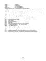
Hinweis: abhängig von der benutzten Kanalkonfiguration ändert sich auf den Kanälen 19 bzw.
9 während der Betriebsart EMG automatisch die Modulationsart.
Kanalkonfiguration
EU
PL
D
EC
U
In
Kanal 19
AM
AM
FM
FM
FM
AM
Kanal 9
AM
AM
AM
FM
FM
AM
Speicherbetrieb (MEM)ory
Ein Druck auf die Taste MEM schaltet auf Speicherbetrieb, dies wird durch ein blinkendes MEM
im Display angezeigt. (Es stehen drei Speicherplätze (M1, M2, M3) zur Verfügung. Auf jedem
Speicherplatz werden neben der Kanalnummer auch die Modulationsart (AM oder FM), die
eventuell eingeschalteten Störunterdrücker sowie das eventuell eingeschaltete Tiefpass-Filter
gespeichert.)
Stellen Sie nun den Kanal ein, den Sie abspeichern möchten. Drücken Sie als nächstes eine der
Speichertasten (z.B. M1 ), bis ein Quittungston ertönt: damit ist der Kanal auf dem Speicherplatz
M1 gespeichert worden. Die Anzeige MEM blinkt nun nicht mehr, sondern erscheint dauerhaft
im Display. Erst wenn über die Kanalwahltasten s oder t ein neuer Kanal eingestellt wird, erlischt
MEM im Display.
Soll ein weiterer Kanal gespeichert werden, stellen Sie wieder mit den Kanalwahltasten s oder
t den gewünschten Kanal ein. Drücken Sie dann erneut MEM und anschließend eine der
Speichertasten (M2 oder M3). Der Quittungston bestätigt den Speichervorgang.
Aufrufen der abgespeicherten Kanäle
Drücken Sie auf MEM und anschließend auf den gewünschten Speicherplatz (M1, M2 oder M3).
Löschen eines Speicherplatzes
Schalten Sie Ihr Funkgerät aus. Halten Sie die Taste des Speicherplatzes, dessen Inhalt Sie
löschen möchten (M1, M2 oder M3), gedrückt, und schalten Sie dabei das Gerät wieder ein.
HF-Abschwächer (LOCAL)
In der Modulationsart AM kann es zu Verzerrungen kommen, wenn der Signalpegel (S-Wert) zu
hoch ist, z.B. bei dicht hintereinander fahrenden Wagen. Dann ist es ratsam, den HF-Abschwächer
zu nutzen: das empfangene Signal wird dabei abgesenkt.
Ein längerer Druck auf die Taste AM/FM schaltet die Funktion LOCAL ein, durch erneuten Druck
wird ausgeschaltet.
Suchlauf (SCAN)
Es gibt zwei verschiedene Varianten des Suchlaufs: entweder werden sämtliche Kanäle der
eingestellten Kanalkonfiguration durchsucht oder nur die von Ihnen belegten Speicherplätze (M1,
M2, M3) und die EMG-Kanäle 19 und 9. Die zweite Variante wird deshalb als Speichersuchlauf
bezeichnet. Beide Varianten des Suchlaufs werden über die Rauschsperre gesteuert. Daher ist
es wichtig die Rauschsperre so einzustellen, dass das Rauschen zwar unterdrückt wird, schwache
Aussendungen aber trotzdem noch empfangen werden.
Ein Druck von ca. einer Sekunde auf die NB/ANL Taste schaltet die Suchlauffunktion SCAN ein.
Befindet sich das Funkgerät im Speichermodus, so wird automatisch der Speichersuchlauf aktiviert,
sonst startet der normale Suchlauf über alle 40 bzw. 80 Kanäle.
In der Frequenztabelle d und eingeschalteter AM wird dabei auf den Kanälen 41-80 automatisch
auf FM umgeschaltet.
In allen anderen Frequenztabellen werden die Kanäl ein der ausgewählten Modulationsart gescannt.
Beim Speichersuchlauf wird die Modulationsart benutzt, die auf den jeweiligen Speicherplätzen
abgelegt wurde.
9
In allen anderen Frequenztabellen werden die Kanäl ein der ausgewählten Modulationsart gescannt.
Beim Speichersuchlauf wird die Modulationsart benutzt, die auf den jeweiligen Speicherplätzen
abgelegt wurde.
Während des Suchlaufs kann mit der MEM Taste vom normalen Suchlauf auf den Speichersuchlauf
und zurück geschaltet werden. Wird der Suchlauf abgeschaltet, so geht das Gerät auf den Kanal
zurück, der eingeschaltet war, bevor der Suchlauf gestartet wurde. Wird das Gerät während des
Suchlaufs auf Senden geschaltet, so verbleibt das Gerät auf dem gerade empfangenen Kanal
und der Suchlauf wird abgeschaltet. Wird auf dem gerade gescannten Kanal ein ausreichend
starkes Signal empfangen, stoppt der Suchlauf und man kann der Aussendung zuhören. Nach
Beendigung der Aussendung bleibt das Gerät für weitere drei Sekunden auf dem Kanal. Wird
dabei kein weiteres Signal empfangen, startet der Suchlauf erneut.
Mit den Tasten für die Kanalwahl s und t lässt sich während des Suchlaufs die Richtung umschalten.
DW (D)ual (W)atch, Zweikanalüberwachung
Mit dieser Funktion können fast zeitgleich ein frei wählbarer Kanal sowie einer der beiden EMG
Kanäle überwacht werden.
Dazu wird mittels der Kanalwahltasten auf den zu überwachenden ersten Kanal geschaltet und
dann die Taste HI-CUT für ca. eine Sekunde gedrückt. Das Gerät schaltet dann auf den zweiten
zu überwachenden Kanal, den EMG Kanal 19. Gleichzeitig wird DW im Display angezeigt.
Soll statt des Kanals 19 der Kanal 9 überwacht werden, drücken Sie erneut für ca. eine Sekunde
auf die Taste HI-CUT.
Stellen Sie dann die Rauschsperre so ein, dass das Rauschen gerade verschwindet. Nach ca.
3 Sekunden beginnt das Gerät, automatisch zwischen den beiden Kanälen zu wechseln. Wird
auf einem der beiden überwachten Kanälen ein ausreichend starkes Signal empfangen, so bleibt
das Gerät auf diesem Kanal stehen. Erst wenn für länger als drei Sekunden kein Signal mehr
auf diesem Kanal empfangen wird, wechselt das Gerät wieder in den DW-Modus. Sollte dagegen
in dieser Zeit auf Senden geschaltet werden, so wird der DW Modus automatisch abgeschaltet.
Die DW-Funktion wird durch längeren Druck (ca. 1 Sek.) auf die Taste HI-CUT ausgeschaltet.
Quittungston (BEEP)
Ein Druck von einer Sekunde auf die Taste CH19/9 schaltet den Quittungston (BEEP) aus und
nach erneutem Druck wieder ein. Im Display wird das anstelle der Kanalnummer für ca. zwei
Sekunden durch bP on oder bP of angezeigt.
S-Meter
Während des Empfangs wird die Stärke des empfangenen Signals durch eine Balkenanzeige im
Display sichtbar gemacht. Dabei handelt es sich um das sogenannte S-Meter. Bei einer Spannung
von 50µV (Mikrovolt) am Empfängereingang wird S9 angezeigt. Signale ab S5 sollten einwandfrei
zu verstehen sein.
Senden (Achtung: Nie ohne angeschlossene Antenne senden!)
Hören Sie zunächst, ob der Kanal frei ist, bevor Sie senden, sonst doppeln Sie mit einer anderen
Station! Denken Sie auch daran, dass der Sender eine gewisse Zeit braucht, bis er hochfährt:
warten Sie deshalb eine Sekunde, bevor Sie Ihre Durchsage beginnen.
Zum Senden drücken Sie die PTT-Taste (Sprechtaste) an der linken Seite des Mikrofons und
sprechen bei gedrückter Taste mit normaler Lautstärke ins Mikrofon. Sprechen Sie nicht zu laut,
damit Ihre Stimme bei der Gegenstation natürlich klingt. (Probieren Sie es einmal aus und lassen
sich einen Modulationsbericht geben.)
Leistungsanzeige
Wenn Sie die PTT-Taste am Mikrofon drücken, wird im Display anstelle des S-Wertes die relative
Ausgangsleistung des Senders angezeigt. Bei AM kann sich die Anzeige im Takt der Modulation
ändern.
10
Entsorgungshinweis
Elektrische und elektronische Geräte gehören nicht in den Hausmüll!
Geben Sie defekte/gebrauchte Geräte bei einer entsprechenden Sammelstelle für Elektroschrott
ab: Informationen dazu erhalten Sie bei Ihrem örtlichen Entsorger oder Ihrer kommunalen
Verwaltung.
Belegung der sechspoligen Mikrofonbuchse
Pin 1
Pin 2
Pin 3
Pin 4
Pin 5
Pin 6
Modulation
RX
TX + Kanalwahltasten
Audioausgang für drahtloses President Mikrofon LIBERTY-MIC
Masse
Stromversorgung
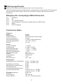
Technische Daten
Allgemein
Kanäle:
Betriebsarten:
Frequenzbereich:
Antennen-Impedanz:
Versorgungsspannung:
Abmessungen (BxHxT):
Gewicht:
80 (40)
AM/FM
26,565 MHz bis 27,99125 MHz
50 Ohm
13,2/26,4 V Gleichspannung
170 x 52 x 150 mm
ca. 1 kg
Sender
Frequenzstabilität:
Sendeleistung:
Nebenausstrahlungen:
Nachbarkanalleistung:
Mikrofon-Empfindlichkeit:
AM-Modulationsgrad:
FM-Hub
Frequenzgang:
Klirrfaktor:
Stromverbrauch:
+/- 300 Hz
4 W AM / 4 W FM
< 4 nW / < -54 dBm
< 20 µW / < -17 dBm
< 5 mV
max. 98 %
max. +/- 2,0 KHz
300-3000 Hz
1,0 %
max. 1,8 A
Empfangsteil
Empfindlichkeit für 20 dB SINAD:
Nachbarkanal-Selektion:
Spiegelfrequenzunterdrückung:
ZF-Unterdrückung:
Intermodulationsunterdrückung:
Squelch-Empfindlichkeit:
NF-Ausgangsleistung:
Klirrfaktor:
Frequenzgang:
Stromverbrauch:
0,4 µV / -115 dBm in FM
0,4 µV / -110 dBm in AM
66 dB
60 dB
80 dB
57 dB
minimum 0,2 µV / -120 dBm
maximum 10 mV / -27 dBm
2,5 W max.
3%
300-3000 Hz
300 mA, 1000 mA maximum
11
Bei Problemen
Sie können nicht oder nur in schlechter Qualität senden:
Wenn Sie die Sendetaste am Mikrofon drücken, muss die Anzeige TX leuchten und Ihr Funkgerät
senden. Lassen Sie die Taste wieder los, so muss diese Anzeige erlöschen und Ihr Funkgerät
wieder auf Empfang schalten.
Prüfen Sie das Stehwellenverhältnis Ihrer Antenne sowie die Zuleitung auf evtl. Unterbrechungen
oder Wackelkontakte!
Sie erhalten auf Ihre Sendung keine Antwort oder haben schlechten Empfang:
Überprüfen Sie, ob eventuell der Abschwächer (LOCAL) eingeschaltet ist.
Stellen Sie den SQ-Regler richtig ein!
Stellen Sie den VOL-Regler auf eine passende Wiedergabe-Lautstärke.
Prüfen Sie das Stehwellenverhältnis Ihrer Antenne sowie die Zuleitung auf evtl. Unterbrechungen
oder Wackelkontakte!
Vergewissern Sie sich, dass Sie dieselbe Modulationsart (AM oder FM) wie Ihr Funkpartner
verwenden!
Die Anzeigen leuchten nicht:
Überprüfen Sie Ihr Netzgerät: Ist es eingeschaltet?
Haben Sie die Anschlüsse für Plus (= ROT) und Minus (=Schwarz) vertauscht? Wechseln Sie
in diesem Fall die Anschlüsse.
Tipps für den Funkverkehr
Nach dem Einschalten des Gerätes immer zuerst hören, ob der eingestellte Kanal frei ist (dazu
die Rauschsperre öffnen, um schwächere Stationen nicht zu überhören)! Nur wenn der Kanal
völlig frei ist, den eigenen Anruf starten.
Immer nur kurz rufen! Nach jedem Anruf sorgfältig hören, ob eine Station antwortet, erst dann
den Anruf wiederholen.
Nach jedem Durchgang der Gegenstation immer erst einige Sekunden Pause lassen, bevor man
selber spricht, damit sich auch andere Stationen melden können ("Umschaltpause").
Internationales Phonetisches Alphabet
Bei schlechten Verbindungen oder starken Störungen ist es häufig problematisch, schwer zu
verstehende Worte wie Eigennamen und Städtenamen fehlerlos zu übermitteln.
Hier hilft das Internationale Buchstabieralphabet weiter, das auch im Luftverkehr (ICAO) und bei
der NATO eingesetzt wird:
A Alpha
F Foxtrott
K Kilo
P Papa
U Uniform
Z Zulu
B Bravo
G Golf
L Lima
Q Quebec
V Victor
C Charlie
H Hotel
M Mike
R Romeo
W Whiskey
D Delta
I India
N November S Sierra
X X-ray
E Echo
J Juliett
O Oscar
T Tango
Y Yankee
Beurteilung der Empfangsqualität
Um dem jeweiligen Gesprächspartner eindeutig sagen zu können, wie stark und klar man ihn
empfängt, verwendet man die Ziffern des R/S-Codes. Dabei steht der R-Wert für die Verständlichkeit
(Readability/Lesbarkeit) und der S-Wert (Signal Strength/Signalstärke) für die Empfangs- bzw.
Lautstärke der Gegenstation.
R = Readability/Lesbarkeit
S = Signal Strength/Signalstärke
Den Wert können Sie am S-Meter im Display ablesen.
1 nicht lesbar, unverständlich
2 zeit- oder teilweise lesbar
3 schwer lesbar
4 lesbar, verständlich
5 gut lesbar
12
CB-Sprache
Im CB-Funk ist ein spezieller Jargon üblich. Einige Fachwörter stammen z. B. aus dem Amateurfunk
oder dem professionellen Funkverkehr, andere Ausdrücke sind Umschreibungen oder Abkürzungen.
Break:
Moment bitte, bitte warten, möchte mitsprechen
Cheerio: Auf Wiederhören
CQ:
allgemeiner Anruf
DX:
Funkverbindung über große Entfernung
Fading: Signal schwankt
Hl:
Ich lache
Mike:
Mikrofon
Müll:
Störungen
Negativ: habe nicht verstanden, nein
OK:
verstanden, richtig, in Ordnung
Roger: Ich habe verstanden, alles einwandfrei empfangen
Skip:
Funkrufname
Standby: Auf Empfang bleiben
Stereo: Zwei Stationen senden gleichzeitig
TVI:
Fernsehstörungen
Q-Gruppen
Häufig werden auch Abkürzungen aus dem international verbindlichen Q-Code verwendet, der
auch im See- oder Amateurfunk Anwendung findet. Mit diesen Drei-Buchstaben-Kürzeln lassen
sich schnell Informationen übermitteln:
QRA:
Mein Stationsname ist...
QRG:
Frequenz, Betriebskanal
QRL:
Beschäftigung, Arbeitsplatz
QRM:
Störung durch andere Stationen
QRN:
Atmosphärische Störungen
QRP:
Arbeiten mit geringer Leistung
QRT:
Ende des Funkverkehrs
QRU:
Es liegen keine weiteren Nachrichten vor.
QRV:
Sende- und empfangsbereit
QRX:
Unterbrechung des Funkverkehrs, Pause, bitte warten
QRZ:
Sie werden gerufen, Anruf von einer bestimmten Station
QSB:
Schwankungen der Feldstärke, Schwund, Fading
QSL:
Empfangsbestätigung
QSO:
Funkverbindung, Gespräch über Funk
QSP:
Vermittlung zweier Stationen für eine dritte
QST:
Durchsage an alle
QSY:
Frequenzwechsel, Kanalwechsel
QTH:
Standort
13
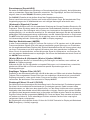
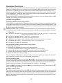
Control elements and connections
10
12
1
2
xm 5006e
4
1
2
3
4
5
6
7
8
9
10
11
12
3
5
6
7
8
9
10 11
LC display
Volume control (VOL) and ON/OFF switch
Squelch (SQ) and A(utomatic) S(quelch) C(ontrol)
Front loudspeaker
Memory mode MEM, Function key F
Type of modulation AM/FM, RF attenuator LOCAL, memory location M1
Noise blanker NB/ANL (Automatic Noise Limiter), scan function SCAN, memory location M2
Hi-Cut filter HI-CUT, dual watch DW, memory location M3
Direct access to channel 19/9 CH19/9, key beep BEEP
Keys for channel selection (CH) switching upwards s and downwards t
6-pin microphone socket (Mic)
Push-to-talk (PTT)
A DC connection 12/24 volts
B Antenna socket, 50 ohms
C Connection for external loudspeaker, 3 watts, 4 - 8 ohms
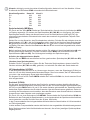
LC display
Displayed for
transmission
TX
SCAN scan
AM
modulation type
FM
modulation type
HI-CUT activated low-pass filter
ASC
activated automatic squelch
DW
activated dual watch function
NB/ANL activated noise limiter
UK
channel configuration MPT 1382
LOCAL activated RF attenuator
EMG
direct access to channel 19/9
MEM
operation in memory mode
F
changing the channel configuration
Channel
Channel
configuration
(EU, PL, d, EC, U, In)
14
Product description
Welcome to the fascinating world of CB radio and congratulations on having purchased the CB
radio set stabo xm 5006e. You have made a decision in favour of a comfortable high-end radio
set which can either be used for mobile operation in your car or as stationary radio set at home
a radio set which provides numerous extra functions.
Features
- 12/24 V mode without switching
- energy-efficient 24V operation without additional heat development
- six switchable frequency tables
EU 40 FM channels/4 watts, 40 AM channels/4 watts
PL 40 FM channels/4 watts, 40 AM channels/4 watts with -5 kHz offset
d
80 FM channels/4 watts, 40 AM channels/4 watts
EC 40 FM channels/4 watts
U 40 channels AM/FM/4 watts (CEPT) + 40 FM channels/4 watts (MPT 1382)
In 27 FM channels FM/4 watts, 27 AM channels/4 watts
- continuous (D)ual (W)atch function
- three memory locations (M1-M3) for your preferred channels
- scan function just for memory locations and for all channels (SCAN)
- direct access to the two trucker and/or emergency channels 9 and 19 (CH19/9)
- switchable NB/ANL circuit (Noise Blanker & Automatic Noise Limiter)
- switchable low-pass filter (HI-CUT)
- switchable key beep (BEEP)
- switchable RF attenuator (LOCAL)
- multifunction LC display indicating the signal strength (S value), the relative transmitting power
as well as the different operation modes.
- clear, penetrating FM and AM modulation.
Scope of delivery
CB radio set stabo xm 5006e
Mounting bracket
Electret microphone with up/down function
User manual
15
Important information
Safety warnings
Persons with cardiac pacemakers are strongly advised to ask a doctor whether he has basically
concerns against the use of a radio set and/or which rules of conduct are to be observed.
Never touch the antenna during the transmission!
Prior to using the radio set in a vehicle, make yourself in any case familiar with its functions and
their operation! Never allow yourself to be distracted by operating the radio set or by radio communications from the current traffic situation!
Never transmit without having an antenna connected!
Never open the housing of a radio set or its accessories and do not carry out any modification.
Ensure that any repair is carried out exclusively by qualified personnel. Modifications of or interventions in the radio set automatically lead to an expiry of the type approval, moreover it voids
all warranty claims!
Prevent children from playing with the radio set, accessories, batteries or the packing material.
Do not operate the radio set, if you detect any damage of the housing or the antenna. Contact
a qualified workshop.
Protect your radio set and the accessories against moistness, heat, dust and strong vibrations.
Avoid operating temperatures below -10°C or above +50°C.
Legal requirements
Operating CB radio sets: In Germany, this radio set is free of charge and can be operated with
channel configuration d, EU, EC and In without any registration. However, different provisions
may apply in other countries: Prior to using the radio set abroad, find out more about the current
national provisions! Be sure to observe the relevant provisions as well as any possible obligation
to register otherwise, you may be risking significant fines or even the confiscation of your radio
set!
Installing a radio set in a vehicle: The manufacturer has specified instructions for the installation
of radio sets and antennas in nearly all types of vehicle: Thus, contact your automobile dealer
for the corresponding manufacturer specifications belonging to your car model. In any case, you
should observe these specifications when installing the radio set, since the type approval of your
vehicle can expire otherwise!
Using voice radio in a vehicle: While the driver of a vehicle is allowed to use mobile phones
only using a hands-free kit or when the vehicle engine is switched off, an express exception to
this rule is provided for radio sets in the German Motor Vehicle Traffic Regulations (Prior to making
trips abroad, find out more about different provisions which may apply!). However, you should
only use your radio set, if the traffic situation permits (please refer also to the safety instructions)!
16
Installation of the radio set
Usage as stationary radio set
If you want to use the stabo xm 5006e as stationary radio set, you are in need of a particular
power supply unit for radio sets (optional) with an output voltage of 13.8 V, a continuous current
of 3 A and an electronically stabilized voltage. Your approved dealer will be happy to advise you
when selecting an appropriate power supply unit.
Usage in a vehicle
If you want to use the stabo xm 5006e as mobile radio set, make sure to observe the given specifications of the vehicle manufacturer when installing the radio set! Position the radio set such that
neither the movement nor the field of view of the driver/front-seat passenger is restricted. Make
sure to provide a rigid, reliable and almost vibrationless mounting of the radio set. Even in the
event of a possible accident it must not present any risk for injury for the vehicle occupants.
Before you fix the mounting bracket using the tapping screws, make sure not to damage any lines
in the vehicle! Furthermore, make sure not to bend any cables or connecting lines and not to
install them on sharp edges or along vehicle components which get hot.
Choose a place for the microphone attachment such that the microphone is always within reach.
Remember that its microphone cord must not interfere with the control elements of the vehicle.
If the space for installing the radio set is so very restricted that the loudspeaker radiation at the
bottom of the radio set is impaired, we recommend you to install an external mobile speaker
(optional). This speaker is connected to the EXT.SP jack (C) situated at the back side of the radio
set. When connecting the external speaker, the internal loudspeaker is automatically deactivated.
Power supply
Your radio set is supplied with a nominal voltage of 13.2/26.4 V. By all means, make sure that
the used polarity is correct, since a reverse polarity could damage your radio set (in spite of the
integrated reverse polarity protection)!
The supply voltage must not exceed 30 V in any case. The negative pole is connected to ground
(= chassis) as for almost all modern vehicles.
Prior to connecting the radio set, check polarity and voltage: If the vehicle is older, the positive
pole can e.g. also be connected to ground. If in doubt, please check with a specialist workshop!
Connection to the vehicle's battery
Your radio set is provided with a power supply cable (A) into which a 2 A fuse is connected. Unless
otherwise provided in the manufacturer's specifications, connect the radio set using the red cable
to terminal 30 (permanent plus) or terminal 15r (radio connection). Connect the black cable (negative pole) to ground using the shortest possible route.
Lay the power supply cable in the car such that the interferences resulting from the ignition system
are as small as possible.
Notes: With a burnt-out fuse: First determine and eliminate the cause and insert a new 2 A fuse
afterwards!
Always switch the radio set off before leaving the vehicle for optimizing the battery life!
Microphone jack
Connect the supplied microphone to the microphone jack at the right front side of the radio set.
Make sure that the recess on the plug is oriented downwards. A packet radio modem (TNC) can
also be connected to this jack.
17
Connection of an external loudspeaker (optional)
At the back side, the radio set is equipped with a jack (C) for connecting an external loudspeaker
with an 8 ohms impedance. For improving the fidelity of reproduction, a loudspeaker can be
connected using a 3.5 mm mono jack plug. Make sure to provide a rigid, reliable and almost
vibrationless mounting of the loudspeaker, too. Even in the event of a possible accident, it must
not present any risk for injury for the vehicle occupants.
Choosing and connecting an antenna
Attention: Transmitting without having an antenna connected would result in a destruction
of your radio set!
The antenna is an important component of the radio equipment and has a major impact on the
reach of the radio set. Depending on the intended usage of the radio set, different antenna types
are available your specialist dealer will be happy to advise you!
Antennas for stationary radio sets
When using a stationary antenna, the maximum range of your radio set is achieved. However
when installing outside antennas, various provisions (antenna grounding, German VDE) have to
be observed: We recommend you to have the antenna system installed by an expert!
Mobile antennas
A distinction is made between tuned and tunable mobile antennas.
Tuned antennas should only be mounted on a great metallic surface (e.g. on the roof of the vehicle
or the trunk lid) assuring a short connection to ground. For an antenna which must be fixed by
drilling a hole into the car body, the body sheet must be thoroughly smoothed until metallically
bright for assuring a good ground connection. Furthermore, make sure not to bend any cables
or connecting lines and not to install them on sharp edges or along vehicle components which
get hot. Connect the antenna cable to jack (B).
Tunable antennas are to be adjusted to the output resistance of the transmitter (50 ohms). The
actual characteristic antenna impedance depends on its length and on its environment of installation.
For this reason, the manufacturer can only provide you with a roughly tuned antenna. Normally
it is designed such that there is always enough scope left for adjusting it to the given conditions.
In practical operation, this means that a new antenna is usually too long.
For adjusting the antenna, connect a VSWR resistance bridge (e.g. President TOS-1, article no.
50004) into the circuit between the radio set and the antenna. Set the radio set to FM modulation
to work always with a constant transmitting power when measuring. Adapt the antenna according
to the manufacturers information such that the VSWR on your preferred channel or one of the
median channels approximates to 1:1 A value of <2.0 is still acceptable. (For mobile operation,
it does not make much sense to adjust a value of 1:1 by all means, since this value is modified
again due to different environments, cable modifications etc.) Regularly check the antenna
adjustment: An unfavourable value points to connector and cable problems!
18
Operation/functions
The operation of the xm 5006e is almost self-explanatory. After having established all connections,
switch your CB radio set on by using the inner control/switch (VOL) which is also used for setting
the volume. The display should be lit now and a channel should appear on the display. If the
display does not light up, please check the power supply and the fuse. A noise should be audible
in the loudspeaker. Failing this, check the microphone for proper connection and turn the outer
control (SQ/ASC) until a noise can be heard.
Please note that ASC is switched on when the squelch control is set to its leftmost position. ASC
appears on the display and the radio set is muted.
Channel configuration
Frequency tables/channel configurations
The xm 5006e is equipped with six switchable frequency tables: Select the corresponding channel
configuration depending on the country in which your radio set shall be operated (factory setting: EU).
In Germany, this radio set is free of charge and can be operated with channel configuration d, EU,
EC and In without any registration.
Important notes: Prior to using the radio set abroad, find out more about the current national
provisions: Be sure to observe the relevant provisions as well as any possible obligation to register!
Channels
EU 40 FM/4 W, 40 AM/4 W free of licence and charges in BE, CH, CY, DK, EE, IS, IT, LT, LU, NO, PT, SE
individual licence/charges required: ES, IT
PL
d
EC
U
In
40 FM/4 W, 40 AM/4 W with -5 kHz offset only allowed in PL
80 FM/4 W, 40 AM/4 W free of licence and charges in DE, CZ
40 FM/4 W free use in all CEPT-countries, in some countries individual licence is required
40 AM/FM/4 W (CEPT) + 40 FM/4 W (MPT 1382) only allowed in GB
27 FM/4 W, 27 AM/4 W allowed in IN
Changing the frequency table/channel configuration
1. Switch the radio set off.
2. Hold the F key pressed and switch on the radio set anew.
The formerly selected channel configuration flashes now on the display.
3. Use the channel selection keys s or t to select one of the six configurations
4. Press the F key anew until a beep sounds and the display stops flashing.
5. Switch the radio set off and on again.
The new channel configuration is now indicated at the bottom right of the display and the radio
set is ready for operation using the new channel configuration.
Channel selection (CH)
Using the two channel selection keys (CH) s and t (or the up/down keys on the microphone),
you can adjust the requested channel which you wish to use for hearing. If a key is pressed for
more than half a second, the Auto Repeat function is activated and the channel automatically
switches to the next channel. The received channel is shown on the display.
If the key BEEP is activated, pressing the s key is confirmed by one beep and pressing the t
key is confirmed by two beeps.
Volume control (VOL)
The volume is set using the inner knob (VOL) of the double potentiometer which is also used for
switching on the radio set. When the receive signal is lacking and the squelch function is deactivated,
the noise should be audible very well in FM modulation. In FM the received speech signal is
always a bit quieter than the noise without signal. After having set the volume, the squelch function
should be activated.
19
Squelch/SQ
The xm 5006e features a function for noise suppression (squelch) suppressing the reproduction,
if the signal is lacking or too weak. Use the SQ/ASC control to adjust the signal level at which
the function is activated.
The SQ/ASC control is the outer knob of the double potentiometer.
By turning the knob to the left, the signal level is reduced, by turning the knob to the right, the
signal level is increased. With constantly varying conditions of reception, as for example during
mobile operation, a frequent adjustment of this level can be necessary.
(A)utomatic (S)quelch (C)ontrol
The ASC function is a patented function elaborated by the President Electronics SA France group.
This function evaluates the so-called signal-to-noise ratio (ratio between the useful signal and the
interfering signal). The useful signal is only forwarded to the loudspeaker, if it is worth being
received, i.e. it is almost free from noise. Thus, a permanent readjustment, as for the squelch
function depending on the field strength, is not necessary. This is of benefit to a safe participation
in the street traffic when driving. The ASC function can be used for AM and FM mode and is
activated if the squelch control is set to the leftmost position. Furthermore, ASC appears on the
display.
Choosing the type of modulation (AM/FM)
In all frequency tables (except EC) you can either operate your radio set in FM or in AM modulation.
Frequency-modulated signals (FM) are less sensitive to interferences resulting from the ignition
system etc. than amplitude-modulated signals (AM). The decision, which type of modulation is
your preferred one, depends on your radio contact partners and on your and/or the legal requirements.
If your loudspeaker emits an unintelligible, distorted signal, you should try receiving the signal
using a different type of modulation. You can change the type of modulation by pressing the
AM/FM key.
(N)oise (B)lanker & (A)utomatic (N)oise (L)imiter (NB/ANL)
Both circuits are used for suppressing interference and are indicated as NB/ANL on the display
when activated.
While ANL only functions in AM mode suppressing above all interferences resulting from generators,
NB functions in AM and FM mode suppressing above all impulse interferences as e.g. interferences
of the ignition system.
Receiver low-pass filter (HI-CUT)
In addition to the noise attenuators ANL and NB, stabo xm 5006e is equipped with a receiver lowpass filter. When the reception quality is poor due to background noise, this filter is able to improve
the subjective hearing quality by filtering high frequencies occurring above all in background noise.
The display shows HI-CUT when the filter is activated.
Direct access to channels 19 and 9 (CH 19/9)
The AM channel 9 is internationally used as emergency call and as truck driver channel especially
in Germany. Outside Germany, channel 19 is used as trucker channel. However, both types of
modulation are used for this purpose. Thus, in case of an accident or another emergency, you
hopefully should be able to quickly appeal for help using these channels. For being able to transmit
an urgent appeal for help as fast as possible in such an emergency situation, your stabo xm 5006e
features an extra key for directly accessing these channels (CH19/9). Thus, pressing this key
once activates channel 19, by pressing this key once again, channel 9 is activated. By pressing
the key once again, the radio set returns to the channel left.
When directly accessing the channels 9 or 19 using the key CH19/9, the display shows EMG
(Emergency) as mode of operation.
Note: In EMG mode, the type of modulation is automatically changed, when the channels 19
and/or 9 are used depending on the selected channel configuration.
20
Channel configuration Channel 19
EU
AM
PL
AM
D
FM
EC
FM
U
FM
In
AM
Channel 9
AM
AM
AM
FM
FM
AM
Memory mode (MEM)
By pressing the MEM key, the radio set switches to memory mode, MEM flashes on the display.
(Three free memory locations (M1, M2, M3) are available each of them storing the type of
modulation (AM or FM), the possibly activated noise attenuators as well as the possibly activated
low-pass filter apart from the channel number.)
Set the channel to be stored. Afterwards press one of the memory keys (e.g. M1) until a beep
sounds. The channel is now stored to memory location M1. MEM is not flashing anymore, but
is permanently shown on the display. MEM does not disappear before a new channel is selected
using the channel selection keys s or t.
For presetting another channel select again the requested channel using the channel selection
keys s or t. Afterwards press MEM again and then one of the memory keys (M2 or M3). The
key beep confirms storage of the channel.
Selecting preset channels
Press MEM and afterwards the requested memory key (M1, M2 or M3).
Deleting a memory location
Switch your radio set off. Hold the respective memory key pressed, the contents of which you
wish to delete (M1, M2 or M3), and switch on the radio set again.
RF attenuator (LOCAL)
With the AM type of modulation, the signal can be distorted, if the signal level (S value) is too
high, e.g. when several vehicles are driving too close to one another. In this case, usage of the
RF attenuator is advised since the received signal is thus reduced.
By longer actuating the AM/FM key, the LOCAL function is activated. By pressing the key once
again, the function is switched off again.
Scan function (SCAN)
The scan function is available in two different versions. You can either search for all channels of
the selected channel configuration or for the preset memory locations (M1, M2, M3) and the EMG
channels 19 and 9 only. For this reason, the second scan version is called memory scan. Both
scan versions are controlled using the squelch function. Thus, it is essential to set the squelch
function such that noise is suppressed but broadcasts with weak signal strength are nevertheless
received.
The scan function SCAN is activated by pressing the NB/ANL key for approx. one second . If the
radio set is set to memory mode, memory scan is automatically activated. Otherwise, scanning
is performed for all 40 or 80 channels.
Using the frequency table d in AM mode,the radio set automatically switches over to FM when
scanning the channels 41-80.
In all other frequency tables the channels are scanned with the selected type of modulation.
For memory scanning, the type of modulation preset for each of the memory locations is used.
During scanning, the radio set can be switched over from normal scan to memory scan and vice
versa by pressing the MEM key. If scanning is deactivated, the radio set returns to the channel
21
activated before scanning was started. If the radio set is switched over to transmit mode during
scanning, the channel received at the moment of switchover remains activated and scanning is
stopped. If the channel scanned receives a signal with sufficient signal strength, scanning stops
and broadcasts can be heard. When broadcasting has finished, the radio set remains adjusted
to the respective channel for another three seconds. If any further signal is not received, scanning
starts again.
By actuating the keys s and t for channel selection, the direction of scanning can be switched
over while the function is activated.
Dual Watch function (DW)
Using this function, a channel which is freely selectable and one of the two EMG channels can
be monitored almost simultaneously.
To do so, switch over to the first channel to be monitored using the channel selection keys and
afterwards press the HI-CUT key for approx. one second. The radio set switches over to the
second channel to be monitored, the EMG channel 19. DW appears on the display.
If you wish to monitor channel 9 instead of channel 19, press the HI-CUT again for another one
second approximately.
Now adjust the squelch function such that the background noise just disappears. After approx.
3 seconds the radio set automatically starts to switch over between both channels. If a signal with
sufficient signal strength is received on one of the two monitored channels, the radio set remains
adjusted to this channel. Only if any signal is not received anymore for more than three seconds,
the radio set again switches over to DW mode. However, if the radio set switches over to transmission
mode during these three seconds, DW mode is automatically deactivated.
The DW function is switched off by holding the HI-CUT key pressed for approx. one second.
Key beep (BEEP)
Key beep (BEEP) is switched off by holding the CH19/9 key pressed for one second and is
switched on again by pressing the key once more. The display shows bP on or bP of for approx.
two seconds instead of the channel number.
S-meter
During reception, the strength of the received signal is shown by means of a bar display. This is
the so called S-meter. With a voltage of 50 µV (microvolts) at the receiver input S9 is indicated.
Reception of signals as of S5 should be perfect and without any problems.
Transmitting (Attention: Never transmit without having an antenna connected!)
Before starting the transmission, listen to make sure that the channel is free and that there is no
doubling with a different radio station! Please note that the radio station needs a certain time
to carry out its start-up sequence: Thus, you should wait for a second before speaking.
For transmitting, you just have to press the PTT button (push-to talk button) on the left side of
your microphone and to speak with normal voice level into the microphone while holding the key
pressed. Dont speak too loud such that the sound of your voice is natural for your radio contact
partner. (Simply give it a try and ask for a modulation report afterwards).
Power display
When pressing the PTT button on your microphone, the display shows the relative transmitting
power instead of the S-value. In AM mode the bar graph may fluctuate depending on the modulation.
22
Disposal instruction
Electric and electronic devices are not to be thrown into the domestic waste.
Deliver devices that are out of order/used with a corresponding collecting point for electronic
scrap. For further information please contact your municipal waste disposal company or your
local authorities.
Assignment of the 6-pin microphone socket
Pin 1
Pin 2
Pin 3
Pin 4
Pin 5
Pin 6
Modulation
RX
TX + channel selection keys
Audio signal for wireless President microphone LIBERTY-MIC
Ground
Power supply
Technical data
General
Channels:
Operation modes:
Frequency range:
Antenna impedance:
Supply voltage:
Dimensions (WxHxD):
Weight:
80 (40)
AM/FM
26.565 MHz to 27.99125 MHz
50 ohms
13.2/26.4 V DC
170 x 52 x 150 mm
approx. 1 kg
Transmitter
Stability of frequency:
Transmitting power:
Spurious radiation:
Adjacent channel power:
Microphone sensitivity:
Degree of AM modulation:
FM hub
Frequency response:
Distortion factor:
Power consumption:
+/- 300 Hz
4 W AM / 4 W FM
< 4 nW / < -54 dBm
< 20 µW / < -17 dBm
< 5 mV
98% max.
max. +/- 2.0 kHz
300-3000 Hz
1.0 %
1.8 A max.
Receiver
Sensitivity for 20 dB SINAD:
Adjacent channel selection:
Image frequency rejection:
IF rejection:
Intermodulation suppression:
Sqelch sensitivity:
AF output power:
Distortion factor:
Frequency response:
Power consumption:
0,4 µV / -115 dBm in FM
0,4 µV / -110 dBm in AM
66 dB
60 dB
80 dB
57 dB
0.2 µV / -120 dBm min.
10 mV / -27 dBm max.
2.5 W max.
3%
300-3000 Hz
300 mA, 1000 mA max.
23
Troubleshooting
Your CB radio set does not transmit at all or transmission power is poor:
With the push-to-talk button activated, TX should be lit and your radio set should start transmission.
By releasing the button once again, the indicator should go out and your radio set should again
switch over to reception mode.
Check the standing wave ratio of your antenna as well as the cable with regard to possible
interruptions or loose contacts!
Your radio set does not receive any response to your transmission or reception is poor:
Check wether the attenuator (LOCAL) is possibly switched on.
Correctly adjust the SQ control!
Adjust the VOL control to an appropriate playback volume.
Check the standing wave ratio of your antenna as well as the cable with regard to possible
interruptions or loose contacts!
Make sure that you are using the same modulation mode (AM or FM) as your contact partner!
The displays do not light up:
Check whether your power supply unit is switched on.
Check the connections for proper wiring: plus pole (= RED) and negative pole (= BLACK)! Exchange
the connections if they are mixed up.
Tips on radio communication
After switching on the radio set, always listen first whether the set channel is free (To do so,
deactivate the squelch function such that you are also able to hear weaker radio stations.)! Start
your own call only if the channel is absolutely free.
Transmit nothing but short calls! After each call carefully listen to a station possibly answering
your call. Repeat your call only after having carefully listened.
After each transmission of your contact partner wait for several seconds before answering in
order to give further radio stations the chance to participate in the radio communication (changeover delay).
International phonetic alphabet
When the radio contact is weak or intense interferences occur, it is quite often difficult to understand
everything perfectly, as e.g. proper names or geographical names.
In this case, you can fall back on the international alphabet which is also applied in air traffic
(ICAO) and NATO communications:
A
B
C
D
E
Alpha
Bravo
Charlie
Delta
Echo
F
G
H
I
J
Foxtrott
Golf
Hotel
India
Juliett
K
L
M
N
O
Kilo
Lima
Mike
November
Oscar
P
Q
R
S
T
Papa
Quebec
Romeo
Sierra
Tango
U
V
W
X
Y
Uniform
Victor
Whiskey
X-ray
Yankee
Z Zulu
Evaluating the reception quality
For informing the respective contact partner clearly on the strength and quality of reception, the
numbers of the R/S code are used. The R-value is used for comprehensibility (readability) and
the S-value (signal strength) for signal strength and/or volume of the contact partner.
S = signal strength
The S-value (= signal strength) can be read
on the S-meter.
R = readability
1 not readable, incomprehensible
2 temporarily or partially readable
3 difficult to read
4 readable, comprehensible
5 easy to read
24
CB Language
Typically a special slang is used in CB radio. Some special terms originate, for instance, from
amateur radio or the professional radio communication, other expressions stand for periphrases
or abbreviations:
Advertising
Flashing lights of police car
Back off
Slow down
Basement
Channel 1
Base station
A CB set in fixed location
Bear
Policeman
Bear bite
Speeding fine
Bear cage
Police station
Big slab
Motorway
Big 10-4
Absolutely
Bleeding
Signal from an adjacent channel interfering with the transmission
Blocking the channel
Pressing the PTT switch without talking
Blue boys
Police
Break
Used to ask permission to join a conversation
Breaker
A CBer wishing to join a channel
Clean and green
Clear of police
Cleaner channel
Channel with less interference
Coming in loud and proud Good reception
Doughnut
Tyre
Down and gone
Turning CB off
Down one
Go to a lower channel
Do you copy?
Understand?
DX
Long distance
Eighty eights
Love and kisses
Eye ball
CBers meeting together
Good buddy
Fellow CBer
Hammer
Accelerator
Handle
CBers nickname
Harvey wall banger
Dangerous driver
How am I hitting you?
How are you receiving me?
Keying the mike
Pressing the PTT switch without talking
Kojac with a kodak
Police radar
Land line
Telephone
Lunch box
CB set
Man with a gun
Police radar
Mayday
SOS
Meat wagon
Ambulance
Midnight shopper
Thief
Modulation
Conversation
Negative copy
No reply
Over your shoulder
Right behind you
Part your hair
Behave yourself - police ahead
Pull your hammer back
Slow down
Rat race
Congested traffic
Rubberbander
New CBer
Sail boat fuel
Wind
Smokey dozing
Parked police car
Smokey with a camera
Police radar
Spaghetti bowl
Interchange
25
Stinger
Turkey
Up one
Wall to wall
What am I putting to you?
Antenna
Dumb CBer
Go up one channel
All over/everywhere
Please give me an S-meter reading
Q groups
Quite often, abbreviations from the internationally binding Q code are used which is also applied
in naval or amateur radio. Thanks to these three-letter acronyms, information can be submitted
very fast:
QRA:
The name of my vessel (or station) is ...
QRG:
Your exact frequency (or that of ...) is ... kHz (or MHz).
QRL:
I am busy (or I am busy with ...). Please do not interfere.
QRM:
Your transmission is being interfered with ... or I am being interfered with
QRN:
I am troubled by static
QRP:
Decrease transmitter power
QRT:
Stop sending
QRU:
I have nothing for you
QRV:
I am ready
QRX:
I will call you again at ... hours (on ... kHz (or MHz))
QRZ:
You are being called by ... (on ... kHz (or MHz))
QSB:
Your signals are fading
QSL:
I am acknowledging receipt
QSO:
can communicate with ... direct (or by relay through ...)
QSP:
I will relay to ... free of charge
QST:
General call to all stations
QSY:
Change to transmission on another frequency (or on ... kHz (or MHz))
QTH:
My position is ... latitude, ... longitude (or according to any other indication)
26
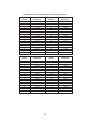
CB-Kanäle und ihre Frequenzen für d / Frequency table for d
Kanal
Channel
Frequenzen
Frequency
Kanal
Channel
Frequenzen
Frequency
1
2
3
4
5
6
7
8
9
10
11
12
13
14
15
16
17
18
19
20
26,965
26,975
26,985
27,005
27,015
27,025
27,035
27,055
27,065
27,075
27,085
27,105
27,115
27,125
27,135
27,155
27,165
27,175
27,185
27,205
21
22
23
24
25
26
27
28
29
30
31
32
33
34
35
36
37
38
39
40
27,215
27,225
27,255
27,235
27,245
27,265
27,275
27,285
27,295
27,305
27,315
27,325
27,335
27,345
27,355
27,365
27,375
27,385
27,395
27,405
Kanal
Channel
Frequenzen
Frequency
Kanal
Channel
Frequenzen
Frequency
41
42
43
44
45
46
47
48
49
50
51
52
53
54
55
56
57
58
59
60
26,565
26,575
26,585
26,595
26,605
26,615
26,625
26,635
26,645
26,655
26,665
26,675
26,685
26,695
26,705
26,715
26,725
26,735
26,745
26,755
61
62
63
64
65
66
67
68
69
70
71
72
73
74
75
76
77
78
79
80
26,765
26,775
26,785
26,795
26,805
26,815
26,825
26,835
26,845
26,855
26,865
26,875
26,885
26,895
26,905
26,915
26,925
26,935
26,945
26,955
27
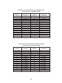
CB-Kanäle und ihre Frequenzen für U(GB) (MPT 1382)
Frequency table for U(GB) (MPT 1382)
Kanal
Channel
Frequenzen
Frequency
Kanal
Channel
1
2
3
4
5
6
7
8
9
10
11
12
13
14
15
16
17
18
19
20
27,60125
27,61125
27,62125
27,63125
27,64125
27,65125
27,66125
27,67125
27,68125
27,69125
27,70125
27,71125
27,72125
27,73125
27,74125
27,75125
27,76125
27,77125
27,78125
27,79125
21
22
23
24
25
26
27
28
29
30
31
32
33
34
35
36
37
38
39
40
Frequenzen
Frequency
27,80125
27,81125
27,82125
27,83125
27,84125
27,85125
27,86125
27,87125
27,88125
27,89125
27,90125
27,91125
27,92125
27,93125
27,94125
27,95125
27,96125
27,97125
27,98125
27,99125
CB-Kanäle und ihre Frequenzen für EU/EC/U(CEPT)
Frequency table for EU/EC/U(CEPT)
Kanal
Channel
Frequenzen
Frequency
Kanal
Channel
1
2
3
4
5
6
7
8
9
10
11
12
13
14
15
16
17
18
19
20
26,965 MHz
26,975 MHz
26,985 MHz
27,005 MHz
27,015 MHz
27,025 MHz
27,035 MHz
27,055 MHz
27,065 MHz
27,075 MHz
27,085 MHz
27,105 MHz
27,115 MHz
27,125 MHz
27,135 MHz
27,155 MHz
27,165 MHz
27,175 MHz
27,185 MHz
27,205 MHz
21
22
23
24
25
26
27
28
29
30
31
32
33
34
35
36
37
38
39
40
28
Frequenzen
Frequency
27,215 MHz
27,225 MHz
27,255 MHz
27,235 MHz
27,245 MHz
27,265 MHz
27,275 MHz
27,285 MHz
27,295 MHz
27,305 MHz
27,315 MHz
27,325 MHz
27,335 MHz
27,345 MHz
27,355 MHz
27,365 MHz
27,375 MHz
27,385 MHz
27,395 MHz
27,405 MHz
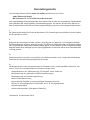
CB-Kanäle und ihre Frequenzen für PL
Frequency table for PL
Kanal
Channel
1
2
3
4
5
6
7
8
9
10
11
12
13
14
15
16
17
18
19
20
Frequenzen
Frequency
Kanal
Channel
26,960 MHz
26,970 MHz
26,980 MHz
27,000 MHz
27,010 MHz
27,020 MHz
27,030 MHz
27,050 MHz
27,060 MHz
27,070 MHz
27,080 MHz
27,100 MHz
27,110 MHz
27,120 MHz
27,130 MHz
27,150 MHz
27,160 MHz
27,170 MHz
27,180 MHz
27,200 MHz
21
22
23
24
25
26
27
28
29
30
31
32
33
34
35
36
37
38
39
40
Frequenzen
Frequency
27,210 MHz
27,220 MHz
27,250 MHz
27,230 MHz
27,240 MHz
27,260 MHz
27,270 MHz
27,280 MHz
27,290 MHz
27,300 MHz
27,310 MHz
27,320 MHz
27,330 MHz
27,340 MHz
27,350 MHz
27,360 MHz
27,370 MHz
27,380 MHz
27,390 MHz
27,400 MHz
CB-Kanäle und ihre Frequenzen für In
Frequency table for In
Kanal
Channel
Frequenzen
Frequency
Kanal
Channel
1
2
3
4
5
6
7
8
9
10
11
12
13
14
15
16
17
18
19
20
26,965 MHz
26,975 MHz
26,985 MHz
27,005 MHz
27,015 MHz
27,025 MHz
27,035 MHz
27,055 MHz
27,065 MHz
27,075 MHz
27,085 MHz
27,105 MHz
27,115 MHz
27,125 MHz
27,135 MHz
27,155 MHz
27,165 MHz
27,175 MHz
27,185 MHz
27,205 MHz
21
22
23
24
25
26
27
29
Frequenzen
Frequency
27,215
27,225
27,255
27,235
27,245
27,265
27,275
MHz
MHz
MHz
MHz
MHz
MHz
MHz
30
Herstellergarantie
Als Hersteller dieses Gerätes stabo xm 5006e gewähren wir, die Firma
stabo Elektronik GmbH,
Münchewiese 16, 31137 Hildesheim/Deutschland
eine selbstständige Garantie gegenüber dem Verbraucher auf alle bei uns gekauften Gegenstände
nach Maßgabe der nachfolgenden Garantiebedingungen. Wir weisen ausdrücklich darauf hin,
dass Ihre gesetzlichen Rechte auf Sachmangelbeseitigung hierdurch nicht eingeschränkt werden.
I.
Die Garantiezeit beträgt fünf Jahre ab Kaufdatum. Die Garantie gilt ausschließlich auf dem Gebiet
der Europäischen Union.
II.
Während der Garantiezeit werden Geräte, die aufgrund von Material- und Fabrikationsfehlern
Defekte aufweisen, repariert, alternativ ersetzt. Die Wahl der Reparatur oder des Ersatzes obliegt
uns. Ausgetauschte Geräte oder Bauteile selbiger gehen in unser Eigentum über. Garantieleistungen
bewirken weder eine Verlängerung der Ursprungsgarantie; es wird auch keine neue Garantielaufzeit
in Gang gesetzt.
III.
Garantieansprüche müssen unverzüglich nach Bekanntwerden unter Vorlage des Kaufbelegs
innerhalb der Garantiezeit geltend gemacht werden.
IV.
Garantieansprüche sind ausgeschlossen bei Schäden durch unsachgemäßen Gebrauch, der
auch in Form eines missbräuchlichen Nutzens erfolgen kann
-
Umwelteinflüsse, wie Überspannung, Feuchtigkeit, Hitze, Staub etc.,
-
Nichtbeachtung der geltenden Sicherheitsvorkehrungen,
-
Nichtbeachtung der Bedienungsanleitung,
-
äußere Gewaltanwendung,
-
eigenmächtige Eingriffe und eigenmächtige Reparaturversuche,
-
Versand in nicht geeigneter Art und Weise, wie z. B. nicht geeignetem
Verpackungsmaterial
-
Verbrauchsmaterialien (Akkupacks, Batterien)
Hildesheim, im September 2014
15
Gibt es Schwierigkeiten,
das neue Gerät in Betrieb zu nehmen?
Hochwertige elektronische
Geräte sind sehr komplex: kleine
Ursachen haben manchmal große
Wirkung! Viele Probleme lassen sich jedoch
schnell und unkompliziert am Telefon lösen.
Schicken Sie deshalb Ihr neues Gerät nicht gleich zurück,
STOP
sondern nutzen Sie die telefonische Beratung des stabo
Service-Teams. Unsere Techniker kennen sich mit
den Geräten sehr genau aus und stehen Ihnen
gerne mit praktischen Tipps und
kompetenten Ratschlägen
zur Seite.
Sie erreichen uns Mo. bis Fr. von 9 -12 Uhr: Telefon 05121-762032
Halten Sie für das Gespräch das Gerät und die Bedienungsanleitung bereit.
stabo Elektronik GmbH . Münchewiese 14 -16 . 31137 Hildesheim/Germany
Tel. +49 (0) 5121-76 20 - 0 . Fax: +49 (0) 5121-51 29 79
Internet: www.stabo.de . E-Mail: [email protected]
32
U01UT403AZZ(0)
Irrtümer und Änderungen vorbehalten. Errors and technical modifications reserved.
Copyright © 11 / 2014 stabo Elektronik GmbH