1
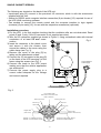
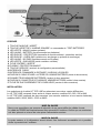
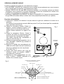
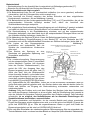
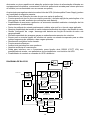
OPERATING PRINCIPLES
In the presence of mains supply, the input voltage is filtered and rectified by a special input circuit
(power factor correction) that optimizes current absorption from the mains, making the power
factor near to 1 and compensating for any voltage variations. This circuit can also supply the
output inverter with very low mains voltages.
This feature is highlighted with very low loads, to the point that, with a load of about 50% of
nominal, mains operation is possible up to 100V line voltage approximately without absorbing
energy from the batteries.
This “intelligent” management of the switchover to battery power is designed to minimize battery
use.
The voltage corrected by the first circuit is then used by a high frequency inverter to generate
“clean” sinusoidal output voltage at very low distortion; a fast synchronized by-pass circuit
intervenes during absorption peaks that exceed the inverter capacity, eg. when switching on
certain peripherals, demagnetization of large colour monitors, and so on.
The absence or excessive drop of the mains voltage automatically activates the booster circuit
which ensures interruption free power supply to the output inverter and, consequently, to the load
using the batteries.
The type of circuit is with direct neutral; i.e. avoiding alteration of the neutral regime of the
apparatus connected to the UPS.
During normal operation, a sensor checks the difference in potential between the neutral
conductor and that of Earth and, if excessive, activates input protection and switches the unit to
battery mode, signalling the anomaly. However, it is possible to have just the indication of
anomaly by modifying the software setting.
All the UPS functions are managed by a microprocessor which also controls and stores particular
operating conditions as well as managing the UPS computer interface via RS232 output. This
makes it possible to check in real time the operating parameters and any anomalies.
5


![(直流)電力回生型電子負荷装置[PLZ6000R]](http://vs1.manualzilla.com/store/data/006557965_2-51751011429bb85ba5bcc9938c75d0ed-150x150.png)