1
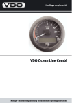
Handling a complex world. Montage- und Bedienungsanleitung Installation and Operating Instructions COMPASS Montage- und Bedienungsanleitung Seite 2 - 20 Installation and Operating Instructions Page 22 - 40 1 INHALT Inhaltsverzeichnis Vorwort . . . . . . . . . . . . . . . . . . . . . . . . . . . . . . . . . . . . . . . . . . . 4 Sicherheitshinweise . . . . . . . . . . . . . . . . . . . . . . . . . . . . . . . . 5 zur Montage . . . . . . . . . . . . . . . . . . . . . . . . . . . . . . . . . . . 5 zur Wartung . . . . . . . . . . . . . . . . . . . . . . . . . . . . . . . . . . . 6 Der VDO Ocean Line Compass . . . . . . . . . . . . . . . . . . . . . . . 7 Die Bestandteile der Anlage . . . . . . . . . . . . . . . . . . . . . . . . . . . 8 Zubehör . . . . . . . . . . . . . . . . . . . . . . . . . . . . . . . . . . . . . . . . . . . 8 Ersatzteile . . . . . . . . . . . . . . . . . . . . . . . . . . . . . . . . . . . . . . . . . 8 Die Anzeigefunktionen des VDO Compass. . . . . . . . . . . . . . 9 Die automatische Kompensation des VDO Compass . . . . 10 Die Einstellung der ortsabhängigen Missweisung. . . . . . . 12 Die Ausrichtung der Kompasssonde. . . . . . . . . . . . . . . . . . 13 Die Fehlersuche. . . . . . . . . . . . . . . . . . . . . . . . . . . . . . . . . . . 13 Die Wartung des VDO Compass . . . . . . . . . . . . . . . . . . . . . 14 Die Installation der VDO Compass-Anlage . . . . . . . . . . . . . 15 Die Installation des Anzeigegerätes . . . . . . . . . . . . . . . . . . . . 15 Die Installation der Kompasssonde . . . . . . . . . . . . . . . . . . . . . 16 Die elektrische Installation . . . . . . . . . . . . . . . . . . . . . . . . . . 18 Die Spannungsversorgung der Anlage . . . . . . . . . . . . . . . . . . 18 Der Anschluss eines Zweitanzeigers. . . . . . . . . . . . . . . . . . . . 19 Schaltplanlegende . . . . . . . . . . . . . . . . . . . . . . . . . . . . . . . . . . 20 Kabellängen. . . . . . . . . . . . . . . . . . . . . . . . . . . . . . . . . . . . . . . 20 Technische Daten . . . . . . . . . . . . . . . . . . . . . . . . . . . . . . . . . 20 2 3 VORWORT Dokument gehört immer an Bord! Vorwort Sie haben sich mit dem Kauf eines Instruments aus dem VDO Marineprogramm für ein qualitativ hochwertiges Produkt entschieden, das nach den anerkannten Regeln der Technik hergestellt wurde. Moderne Fertigungsverfahren und die Beachtung der derzeit gültigen Qualitätssicherungsnormen gewährleisten, dass unsere Produkte das Werk in einwandfreiem Zustand verlassen. Wir danken Ihnen für Ihre gute Wahl und sind überzeugt, daß Ihnen dieses System auf See gute Hilfe und Sicherheit bieten wird. Um einen einfachen und sicheren Umgang mit Ihrem VDO Compass zu gewährleisten, sollten Sie sich mit sämtlichen Funktionen der Anlage vertraut machen. Bitte nehmen Sie sich die Zeit, die vorliegende Anleitung aufmerksam und vollständig zu lesen. © Copyright by Siemens VDO Trading GmbH 2004 Alle Rechte vorbehalten 4 SICHERHEIT Sicherheitshinweise Befolgen Sie alle in diesem Handbuch aufgeführten Anweisungen genau. Beachten Sie bitte besonders alle Textpassagen, welche mit diesem Symbol gekennzeichnet sind. Es sind Hinweise, die für den Betrieb der Anlage und für Ihre Sicherheit besonders wichtig sind. Der Gebrauch der Compassanlage entbindet Sie nicht von der Verantwortung über Ihr Schiff und verlangt gute Seemannschaft. Benutzen Sie zur Interpretation der angezeigten Werte zusätzlich auch immer Ihre seemännische Erfahrung! Sicherheitshinweise zur Montage: Den Einbau der Compassanlage sollten Sie von Ihrer Werft oder von einem darauf spezialisierten Fachmann ausführen lassen. Nehmen Sie die Arbeiten selbst vor, tragen Sie geeignete Arbeitskleidung. Tragen Sie keine weite Kleidung. Tragen Sie bei langen Haaren ein Haarnetz. Kleidung und Haare können von beweglichen und rotierenden Teilen erfaßt werden. Bei Arbeiten an der Bordelektrik ist das Tragen von metallischem oder leitfähigem Schmuck wie Ketten, Armbändern, Ringen etc. nicht zulässig. Vor Beginn der Arbeiten ist der Minuspol der Batterie abzuklemmen, da sonst Kurzschlußgefahr besteht. Kurzschlüsse können Kabelbrände, Batterieexplosionen und Beschädigungen von anderen elektronischen Systemen verursachen. Bitte beachten Sie, daß beim Abklemmen der Batterie alle flüchtigen elektronischen Speicher ihre eingegebenen Werte verlieren und neu programmiert werden müssen. Die VDO Instrumente sind mit nicht flüchtigen Speichern ausgerüstet. Explosionsgefahr! Lassen Sie vor Beginn der Arbeiten im Motorraum bei Benzinmotoren den Motorraumlüfter laufen. Achten Sie am Einbauort des Anzeigers auf den nötigen Freiraum hinter der Einbauöffnung. Einbauöffnung mit Bohrer vorbohren und mit Lochoder Stichsäge fertigstellen (auf die Sicherheitshinweise der Handwerkzeughersteller achten). 5 SICHERHEIT Achten Sie bei der Wahl des Einbauortes für den Geber darauf, dass keine Stringer angebohrt werden. Achten Sie auch auf Möbel, Bodenbretter, Backskisten, Leitungen, usw.. Bei Installationsarbeiten mit Dichtmasse können Lösungsmitteldämpfe entstehen. Sorgen Sie für ausreichende Lüftung. Beachten Sie die Verarbeitungshinweise des Herstellers der Dichtmasse. Bei notwendigen Arbeiten ohne Spannungsunterbrechung darf nur mit isoliertem Werkzeug gearbeitet werden. Die elektrischen Anschlüsse des Compass-Anzeigegerätes und die daran angeschlossenen Leitungen müssen vor direkter Berührung und Beschädigung geschützt werden. Kondensatoren im Gerät können noch geladen sein, selbst wenn das Gerät von allen Spannungsquellen getrennt wurde. Die verwendeten Leitungen müssen eine ausreichende Isolation bzw. Spannungsfestigkeit besitzen und die Kontaktstellen berührungssicher sein. Auch die elektrisch leitenden Teile der angeschlossenen Verbraucher sind durch entsprechende Maßnahmen vor direkter Berührung zu schützen. Das Verlegen metallisch blanker Leitungen und Kontakte ist nicht zulässig. Sicherheitshinweise zur Wartung: Reparaturen an den Komponenten der Compassanlage dürfen nur von autorisierten Fachkräfte durchgeführt werden. Die VDO Compassanlage entspricht den einschlägigen Sicherheitsbestimmungen. 6 VDO COMPASS Der VDO Compass Analogskala Display Taster Der VDO Compass ist ein elektronisches Kursanzeigegerät, das für den Einsatz in der Sportschiffahrt bestimmt ist. Das Gerät verfügt über einen Taster auf der Gerätevorderseite, mit dem die Betriebsarten Kursanzeige oder Sollkurs mit Abweichung aktiviert werden können. In der Betriebsart Kursanzeige wird im Display der anliegende Kurs angezeigt und der Zeiger befindet sich in der Stellung OFF. In der Betriebsart Sollkurs mit Abweichung wird im Display der Sollkurs angezeigt und der Zeiger stellt die Kursabweichung auf der Analogskala dar. Die Auswahl der gewünschten Betriesart wird durch einfachen Druck auf den Taster getroffen. Die Handhabung des Gerätes ist dadurch einfach und unkompliziert. Es können maximal 2 weitere Anzeiger angeschlossen werden. Außerdem ist ein NMEA-Interface (VDO Nr. N01 610 506) als Zubehör erhältlich. Mit diesem können Daten zum VDO MAP oder zum PC übertragen werden. 7 VDO COMPASS Die Bestandteile der Anlage Im Lieferumfang sind enthalten: - Anzeigegerät Mutter zur Befestigung des Anzeigegerätes Fluxgate-Kompasssonde mit Anschlusskabel, 1 m Warnaufkleber rotes Verbindungskabel Kompasssonde - Anzeiger, 10 m Montage- und Bedienungsanleitung Zubehör (nicht im Lieferumfang enthalten): - Teilesatz Befestigung (Bügel) Teilesatz Beleuchtung (24V / 1,2W) 2. Anzeigegerät VDO Compass N05 800 792 N05 800 550 N01 512 002 Ersatzteile: - Teilesatz Beleuchtung (12V / 1,2W) Fluxgate-Kompasssonde N05 800 552 N01 530 302 Weitere Ersatzteile sind auf Anfrage erhältlich. 8 ANZEIGEFUNKTIONEN Die Anzeigefunktionen des VDO Compass Nach dem Einschalten der Spannungsversorgung werden am Anzeiger folgende Kursinformationen angezeigt: 1. Betriebsart Kursanzeige Im Display wird der anliegende Steuerkurs (hier 267°) angezeigt. Der Zeiger befindet sich in der OFF-Stellung und ist ohne Funktion. 267 2. oder Betriebsart Sollkurs mit Abweichung Im Display wird permanent der Sollkurs angezeigt. Diese Kursangabe ist mit einem S vor dem Wert (hier 270°) gekennzeichnet. Der Zeiger gibt gleichzeitig die Abweichung vom Sollkurs (hier 3° backbord) an. S 270 Es erfolgt jeweils diejenige Anzeige (1 oder 2), die vor dem letzten Ausschalten der Spannungsversorgung ausgewählt wurde. Zwischen beiden Anzeigefunktionen kann durch Drücken des Tasters gewählt werden. Soll ein bestimmter Kurs als Sollkurs angezeigt werden, muss sich der Anzeiger in der Betriebsart Kursanzeige befinden. Bringen Sie Ihr Schiff auf den gewünschten Sollkurs und drücken Sie den Taster. Der anliegende Steuerkurs wird nun als Sollkurs übernommen und der Zeiger bewegt sich in die Mittelstellung (Abweichung 0°). Bei einer Abweichung vom Sollkurs erfolgt die Anzeige dieser analog mittels des Zeigers (hier 3° backbord). 9 KOMPENSATION Die automatische Kompensation des VDO Compass Alle Eisenmassen an Bord eines Schiffes besitzen einen mehr oder weniger starken Eigenmagnetismus, der einen Einfluss auf den Kompass ausübt. Dieser Einfluss muss in seiner Wirkung auf einen Fluidkompass, sowie auf einen Fluxgate-Kompass kompensiert werden. Was bei herkömmlichen Fluidkompassen ein autorisierter Fachmann durchführen muss, können Sie beim VDO Compass dank des automatischen Deviationsabgleichs selbst einfach und zuverlässig durchführen. Im Auslieferungszustand verhält sich der VDO Compass wie ein gewöhnlicher, nicht kompensierter Fluidkompass. Die automatische Kompensation führen Sie während einer Kreisfahrt bei ruhiger See und fernab von Hafenanlagen und magnetischen Störquellen (z.B. Stahlbrücken, Spundwände, andere Schiffe) durch. Der Kreisfahrtdurchmesser muss die fünf- bis sechsfache Schiffslänge betragen. Die Geschwindigkeit sollte so angepasst werden, dass eine Kreisfahrt mindestens 2 Minuten dauert. Während der Kompensation wird kein gültiger Kurs durch das Instrument angezeigt. Führen Sie den Abgleich wie folgt durch: Bringen Sie ihr Schiff auf Kreisfahrt und schalten Sie bei gedrückt gehaltenem Taster die Spannungsversorgung ein. Auf dem Display wird OFFSET angezeigt. OFFSET Lassen Sie bei Anzeige von OFFSET den Taster los. Nach wenigen Sekunden erfolgt die Anzeige der örtlichen Missweisung (Einstellung s.S.12). OS 000 Nach weiteren ca. 5 Sekunden wird im Display automatisch CAL angezeigt. Drücken Sie den Taster während der Anzeige von CAL, bis CAL1 angezeigt wird. Der Zeiger bewegt sich in die CAL-Position. CAL Taster drücken CAL 1 (Hinweis: Sie haben ca. 5 Sek. Zeit, die CAL-Funktion zu starten, da 10 KOMPENSATION nach Ablauf dieser Zeit diese Funktion automatisch verlassen wird.) Die automatische Kompensation wird nun durchgeführt. Setzen Sie die Kreisfahrt fort, bis im Display --- angezeigt wird. --Starten Sie nun die zweite Kreisfahrt in entgegengesetzter Richtung. Drücken Sie den Taster bis im Display CAL 2 erscheint. CAL 2 Setzen Sie die Kreisfahrt fort, bis die Kompensation automatisch beendet wird. Nach erfolgreich beendeter Kompensation erfolgt die Kursoder Sollkursanzeige (hier 267° bzw. 270°). 267 oder s 270 Zu Ihrer eigenen Sicherheit empfehlen wir die Überprüfung der Anzeige durch mehrere rechtweisende Peilungen (rwP) auf verschiedenen Kursen (Nord, Ost, Süd, West). Sollten Unterschiede zwischen Kompassanzeige und rwP festgestellt werden, so muss dieser Fehler durch die korrekte Ausrichtung der Kompasssonde beseitigt werden (s.S.13). Ist die automatische Kompensation fehlgeschlagen, wird im Display FAIL angezeigt, oder die Kompensation kann nicht beendet werden. FAIL In diesem Fall muss die erfolglose Kompensation durch Ausschalten der Spannungsversorgung abgebrochen werden werden. Nach erneutem Einschalten kehrt der Anzeiger zu einer der normalen Betriebsarten zurück. Führen Sie die automatische Kompensation erneut durch. Folgende Faktoren können dazu führen, dass die automatische Kompensation nicht erfolgreich abgeschlossen werden kann: Die Kreisfahrt wurde mit zu hoher Geschwindigkeit durchgeführt. Der Installationsort für die Sonde ist ungeeignet (s.S.16). Die Benutzung von Mobiltelefonen oder Funksprechanlagen während der Kompensation. Der Einfluss magnetischer Störquellen (Brücken, Spundwände, etc.) oder magnetischer Gegenstände in Sondennähe. 11 ORTSMISSWEISUNG Die automatische Kompensation sollte nach der Neuinstallation des Kompass, nach jedem Abslippen, vor grösseren Törns, nach Schweissarbeiten, nach der Installation elektrischer Verbraucher, mindestens jedoch einmal pro Jahr durchgeführt werden. Beachten Sie auch den bei Stahlschiffen auftretenden Effekt des halbfesten Magnetismus. Dieser tritt auf, wenn das Schiff über einen längeren Zeitraum (z.B. im Winterlager) der Induktionswirkung des Erdmagnetfeldes in gleicher Richtung ausgesetzt wird. Der Effekt kann nach einigen Tagen im Wasser wieder verschwunden sein. Deshalb sollte nach der Wasserung eines Stahlschiffes die Kompensation nach einigen Tagen wiederholt werden. Die Einstellung der ortsabhängigen Missweisung Diese Einstellung ist notwendig, um die für Ihr Revier gültige, örtliche Missweisung (Variation) einzustellen. Der Winkelwert für die Variation wird der Seekarte entnommen. Die Einstellung der Variation erleichtert die Kartenarbeit und der Kompass zeigt bei erfolgter Kompensation (s.S.10) den rechtweisenden Kurs an. Nehmen Sie die Eingabe der Missweisung wie folgt vor: Schalten Sie bei gedrückt gehaltenem Taster die Spannungsversorgung ein. Der Zeiger befindet sich in der OFF-Position und auf dem Display wird OFFSET angezeigt. OFFSEt Lassen Sie bei Anzeige von OFFSET den Taster los. Nach wenigen Sekunden erfolgt die Anzeige der örtlichen Missweisung. Dieser Wert beträgt im Auslieferungszustand der Anlage 0. OS 000 (Hinweis: Sie haben ca. 5 Sek. Zeit, die OFFSET-Funktion zu starten, da nach Ablauf dieser Zeit die Funktion automatisch verlassen wird.) Pro Druck auf den Taster erhöht sich der Wert um 1°. Halten Sie den Taster gedrückt, erhöht sich der Wert mit steigender Geschwindigkeit bis 100° und fällt anschliessend von -100° wieder ab. Positiver Einstellwert = Missweisung in Ostrichtung. Negativer Einstellwert = Missweisung in Westrichtung. 12 AUSRICHTUNG / FEHLERSUCHE Nachdem der korrekte Wert eingestellt ist (hier 3°), lassen Sie den Taster los. Nach wenigen Sekunden wechselt die Anzeige automatisch zur Einstellfunktion CAL. Nach weiteren ca. 5 Sekunden erfolgt die Anzeige einer normalen Kursinformation (hier Steuerkurs 267°) unter Berücksichtigung der Missweisung. OS 003 CAL 267 Der eingestellte Wert für die Missweisung bleibt auch nach dem Ausschalten des VDO Compass gespeichert. Die Ausrichtung der Kompasssonde Sollten nach erfolgter Kompensation und Einstellung der Missweisung noch Unterschiede zwischen den (rechtweisenden) Kompasskursen und den rechtweisenden Peilungen (rwP) festgestellt werden, muss dieser Fehler durch die korrekte Ausrichtung der Kompasssonde beseitigt werden. Notieren Sie auf jedem Kurs (N, E, S, W) die Differenzen der Messungen. Differenz = rwP - Kompassanzeige (z.B.: rwP: 001°, VDO Compass: 002°, Differenz Nord : -001°). Errechnen Sie anschliessend den Mittelwert der Differenzen. Der Mittelwert ist der Winkelwert, um den die Kompasssonde gedreht werden muss, um sie korrekt auszurichten. Bei positivem (+) Vorzeichen des Mittelwertes erfolgt die Drehung der Sonde im Uhrzeigersinn, bei negativem (-) Vorzeichen entgegen dem Uhrzeigersinn. Die Fehlersuche Fehler: Ursache/ Behebung: - Compass ohne Funktion - Elektrische Anschlüsse gemäß Installationsplan überprüfen - Bordspannung überprüfen, Versorgungsspannung 10,8....32 V 13 WARTUNG - Kompensation nicht möglich Anzeige FAIL oder Kompensation kann nicht abgeschlossen werden - Installationshinweise der Sonde beachten - magnetische Störquellen (Brücken, Spundwände etc.) während der Kreisfahrt meiden, - magnetische Störquellen in Sondennähe (Dosen, Werkzeug, etc.) entfernen. - Kabelverbindung Anzeiger- Sonde prüfen (Wackelkontakt ?) - Falsche Anzeige - Automatische Kompensation durchführen - Kompasssonde korrekt ausrichten - Örtliche Missweisung einstellen - Krängungsfehler (Anzeigefehler bei Krängung des Schiffes) - Magnetische Störungen oberhalb bzw. unterhalb der Sonde - Störquellen beseitigen - Anderen Montageort für Sonde wählen - Display zeigt - Verbindung Anzeiger- Sonde ist unterbrochen - Kompasssonde defekt - Kabelverbindung und Kontaktierung prüfen Die Wartung des VDO Compass Das Anzeigegerät und die Kompasssonde sind wartungsfrei. Benutzen Sie zur Reinigung des Anzeigegerätes ein sauberes feuchtes, oder antistatisches Tuch. Das Deckglas besteht aus Kunststoff. Um Kratzer und Schlieren zu vermeiden, verwenden Sie bitte keine Reinigungsmittel. 14 INSTALLATION Die Installation der VDO Compass-Anlage Bevor Sie mit der Montage beginnen, lesen Sie bitte die Sicherheitshinweise auf den Seiten 5 und 6. Die Installation des Anzeigegerätes - Bringen Sie an geeigneter Stelle eine Bohrung mit einem Durchmesser von 86 mm an. Reinigen Sie den Untergrund vor dem Einsetzen des Anzeigegerätes und entfernen Sie die Bohrspäne. Führen Sie die Kabelverbindungen zum Anzeigegerät hinter der Montagebohrung durch die Gehäusemutter hindurch. - A oder B d - - Legen Sie den mitgelieferten, schwarzen Gummiring auf die Geräterückseite. Setzen Sie das Anzeigegerät nach Herstellung der Kabelverbindungen laut Anschlussplan (siehe Die elektrische Installation) in die Montagebohrung ein. Befestigen Sie das Anzeigegerät durch Festschrauben der Gehäusemutter. Montagevariante A für Wandstärke d= 0,5 bis 6,5 mm, Montagevariante B für Wandstärke d= 6,5 bis 16,5 mm. Achten Sie darauf, dass die Gehäusemutter nur handfest angezogen wird. Montieren Sie den Anzeiger mit Bolzen und Bügel (s.S16 oben), wenn starke Schwingungsbeanspruchung am Einbauort zu erwarten ist (z.B. bei Hochgeschwindigkeitsbooten). 15 INSTALLATION 1,5 Nm max. 1,5 Nm max. Teilesatz Befestigung N05 800 792 (Zubehör) Bolzen hier einschrauben Bolzen hier einschrauben Die Installation der Kompasssonde Das Erdmagnetfeld wird nach dem Fluxgate-Prinzip über zwei kreuzförmig ineinanderliegende Spulen nach Richtung und Stärke gemessen. Bei Holz-, GFK-, Kevlar- und Aluminiumrümpfen kann die Sonde im Rumpf montiert werden. Bei Stahl- und Ferrozementrümpfen muss die Sonde mindestens 1 m über Deck, jedoch nicht höher als 5 m montiert werden. Achten Sie bei der Montage der Sonde auf ausreichenden Abstand zu festmontierten Eisenteilen, elektrischen Leitungen und sonstigen magnetfelderzeugenden Objekten. Beachten Sie auch ausreichende Abstände zu allen beweglichen Störquellen wie Konservendosen, Bratpfannen, Radios, Mobiltelefonen in Betrieb, usw. 16 INSTALLATION Montieren Sie die Sonde zunächst provisorisch und führen Sie die erste automatische Kompensation durch. Gelingt diese nicht nach mehreren Versuchen, muss ein anderer Montageort gewählt werden. Ist ein geeigneter Montageort für die Sonde gefunden, befestigen Sie die Sonde mit drei Messing- oder Niroschrauben so, dass ein späteres Verdrehen der Sonde zur Ausrichtung (s.S.13) möglich ist. Kennzeichnen Sie den Montageort der Sonde mit dem beiliegenden Warnaufkleber. Markierungsstrich Mittschiffslinie Ansicht von oben: Höhe max.40 mm Bug Æ max. 90 mm Winkelmarkierungen zur Sondenausrichtung (5°) Æ max. 120 mm Lochkreis-Æ 105 mm Verwenden Sie zur Montage der Sonde niemals Stahlschrauben (Magnetismus). Die Sonde ist grundsätzlich in waagerechter Position auf einer horizontalen Fläche zu montieren und zu lagern. Der Markierungsstrich auf der Sonde muss immer in, bzw. parallel zur Mittschiffslinie in Richtung Bug weisen. Nach jedem Umstauen der Ladung muss die automatische Kompensation erneut durchgeführt werden. 17 INSTALLATION Die elektrische Installation Die Spannungsversorgung Verbindungskabel Kompasssonde-Anzeiger 8 5 3 4 2 1 Beleuchtung Schaltplanlegende s.S.20 18 S2 F2 S1 F1 + INSTALLATION Der Anschluss eines Zweitanzeigers Die Spannungsversorgung für den Zweitanzeiger ist wie beim Hauptanzeiger vorzunehmen (s.S.18). Die Spannungsversorgung der Anzeiger muss gleichzeitig eingeschaltet werden. Der Anschluss der Sonde kann an einem beliebigen Anzeiger erfolgen. Die Verbindung zwischen Haupt- und Zweitanzeiger ist wie unten dargestellt auszuführen. 8 4 Hauptanzeiger 8 Zweitanzeiger 4 Die automatische Kompensation CAL braucht nur an einem Anzeiger ausgeführt werden. Dies gilt auch bei nachträglicher Installation eines Zweitoder Drittanzeigers. 19 INSTALLATION / DATEN Schaltplanlegende S1 S2 F1 F2 Ein/Aus-Schalter Navigationsinstrumente Ein/Aus-Schalter Instrumentenbeleuchtung Sicherung Navigationsinstrumente (5A) Sicherung Instrumentenbeleuchtung (5A) empfohlener Kabelquerschnitt: 1,5 mm2 Kabellängen Kompasssonde - Anzeigegerät Anzeigegerät - Zweitanzeiger Zweitanzeiger - Drittanzeiger max. 20 m max. 10 m max. 10 m Technische Daten Messprinzip: Fluxgate-Magnetfeldmessung, Spulensystem flüssigkeitsgedämpft Genauigkeit: ± 3° nach Kompensation Einsatzbereich: Feldstärke: 8 bis 50 A/m max. Neigungswinkel in Stampf- und Rollrichtung: ± 30° Versorgungsspannung: 10,8 bis 32 V DC Stromaufnahme: Anzeiger: ca. 90 mA bei 12 VDC ohne Beleuchtung ca. 250 mA mit Beleuchtung Geber: ca. 50 mA bei 12 VDC Betriebstemperatur: -10 bis +60°C Schutzart: Anzeigegerät: DIN 40050 - IP 65 frontseitig Kompasssonde: DIN 40050 - IP 65 EMV-Schutz: CE: EN 50081-1, EN 50082-1 Abmessungen: Anzeigegerät: 105 mm Frontringdurchmesser 86 mm Einbaudurchmesser 56 mm Einbautiefe (Mutter) 90 mm Einbautiefe (Bügel) Kompasssonde: siehe Darstellung S.17 20 Technische Änderungen vorbehalten Installation and Operating Instructions Page 22 - 40 21 CONTENT Contents Preface . . . . . . . . . . . . . . . . . . . . . . . . . . . . . . . . . . . . . . . . . . 24 Safety Instructions . . . . . . . . . . . . . . . . . . . . . . . . . . . . . . . . 25 for installation . . . . . . . . . . . . . . . . . . . . . . . . . . . . . . . . . 25 for maintenance . . . . . . . . . . . . . . . . . . . . . . . . . . . . . . . 26 The VDO Ocean Line Compass . . . . . . . . . . . . . . . . . . . . . . 27 System components . . . . . . . . . . . . . . . . . . . . . . . . . . . . . . . . 28 Accessories . . . . . . . . . . . . . . . . . . . . . . . . . . . . . . . . . . . . . . . 28 Spare parts . . . . . . . . . . . . . . . . . . . . . . . . . . . . . . . . . . . . . . . 28 The indicating functions of the VDO Compass . . . . . . . . . 29 Automatic compensation of the VDO Compass . . . . . . . . 30 Setting of the position-dependent variation . . . . . . . . . . . . 32 Adjustment of the compass sensor. . . . . . . . . . . . . . . . . . . 33 Troubleshooting . . . . . . . . . . . . . . . . . . . . . . . . . . . . . . . . . . 33 Maintenance of the VDO Compass . . . . . . . . . . . . . . . . . . . 34 Installation of the VDO Compass . . . . . . . . . . . . . . . . . . . . . 35 Installation of the indicating instrument . . . . . . . . . . . . . . . . . . 35 Installation of the compass sensor . . . . . . . . . . . . . . . . . . . . . 36 Electrical installation. . . . . . . . . . . . . . . . . . . . . . . . . . . . . . . 37 System power supply . . . . . . . . . . . . . . . . . . . . . . . . . . . . . . . 38 Connection of a secondary indicating instrument . . . . . . . . . . 39 Legend of the circuit schematic . . . . . . . . . . . . . . . . . . . . . . . . 40 Cable lengths. . . . . . . . . . . . . . . . . . . . . . . . . . . . . . . . . . . . . . 40 Technical data . . . . . . . . . . . . . . . . . . . . . . . . . . . . . . . . . . . . 40 22 23 SAFETY This document should always stay on board Preface With the purchase of an instrument of the VDO Marine program you selected a high-quality product, made to the accepted State of the Art. Advanced production methods and the respect of the applicable quality assurance standards guarantee that our products are shipped in excellent condition. Thank you for your sound decision. We are certain that this system will provide you with valuable assistance and safety at sea. You should be familiar with all functions of the unit to guarantee easy and safe use of your VDO Compass. Please take the time to completely study this manual. © Copyright by Siemens VDO Trading GmbH 2004 All rights reserved 24 SAFETY Safety instructions Please respect all instructions of this manual. All texts marked with this symbol should have your particular attention. They are indications of particular importance for the operation of the system and for your safety. The use of the compass system does not relieve you of the responsibility for your ship, and requires good seamanship. Always rely on your nautical experience for the interpretation of the indicated values. Safety Instructions concerning the installation: The compass system should be installed by your shipyard or by a specialist. Use adequate working clothes if you install it yourself. Avoid loose clothing. Use a hair net if you have long hair. Clothing and hair may be caught by moving parts. Remove all metallic or electrically conducting jewelry, such as chains, bracelets, rings, etc. when working on the on-board electrical system. Disconnect the minus polarity of the battery before starting your work to prevent the risk of a short-circuit. Short-circuits can cause harness fires, battery explosions and damages of other electronic memory systems. Please note that all volatile electronic memories will lose their contents, and will have to be re-programmed if you disconnect the battery. VDO instruments are not equipped with volatile memories. Risk of explosion! Run the engine blower for a certain time before starting work in a gasoline engine compartment. Check for sufficient clearance behind the mounting hole when selecting the location for the indicating instrument. Pre-drill the hole and finish with hole or keyhole saw (respect the safety instructions of the tool manufacturer). 25 SAFETY Check that no stringers are damaged when selecting the location for the sensor installation. Check for furniture, floor boards, boxes, cables, etc. Solvent vapors may be produced when working with sealants. Provide sufficient ventilation. Respect the recommendations given by the sealant manufacturer. Use insulated tools if you must work without disconnecting the power supply. The electrical connections of the compass indicating instrument and the cables connected to the unit must be protected against direct contact or damage. Capacitors in the equipment could still be charged, even if the power supply of the unit has been disconnected. Use cables with sufficient insulation thickness or voltage rating, and protect the connections against direct contact. Electrically conducting parts of the connected consumers shall also be protected against direct contact by adequate measures. The use of noninsulated wires and contacts is strictly forbidden. Safety instructions concerning the maintenance: Repairs of the compass system components shall only be made by authorized specialists. The VDO Compass meets the corresponding safety regulations. 26 VDO COMPASS The VDO Compass Analog dial Display Pushbutton The VDO Compass is an electronic course indicator designed for the use in sports ships. The unit has a pushbutton on the front. It serves for the activation of the operating modes course indication and desired course with deviation. In course indication mode the display shows the current course, the pointer is in the OFF position. In desired course with deviation mode the display indicates the desired course, the pointer indicates the deviation on the analog dial. The desired mode is selected by pushing the button. The use of the instrument is simple and uncomplicated. A maximum of two more indicating instruments can be connected. An NMEA Interface VDO Number N01 610 506 is also available as an accessory. This can be used to transmit data to the VDO MAP or to the PC. 27 VDO COMPASS Components of the system The supplied kit contains: - Indicating instrument Union nut for instrument fixation Fluxgate compass sensor with connecting cable, length 1 m Warning label Red connecting cable compass sensor - indicating instrument, length 10 m Installation and operation manual Accessories (must be ordered separately): - Fixation kit (bracket) Lighting kit (24 V / 1.2 W) 2nd indicating instrument VDO Compass N05 800 792 N05 800 550 N01 512 002 Spare parts: - Lighting kit (12 V / 1.2 W) Fluxgate compass sensor Other spare parts are available on request. 28 N05 800 552 N01 530 302 INDICATING FUNCTIONS The indicating functions of the VDO Compass The indicating instrument displays the following course information when the power is switched on: 1. Course indication mode The display indicates the steered course (267° in the example). The pointer is in OFF position and has no function. 267 2. or Desired course with deviation The display continuously indicates the desired course. This course indication (270° in the example) is preceded by a S. At the same time the pointer indicates the deviation from the desired course (3° port in this case). S 270 The indication corresponds to the active mode (1 or 2) when the power supply was shut off. The pushbutton toggles between both indicating modes. The indicating instrument must be in course indication mode to indicate a specific course as the desired course. Set the ship to the desired course and push the button. The current course is stored as the desired course, and the pointer moves to center position (deviation 0°). Each deviation from the desired course is indicated by the analog pointer (3° port in this case). 29 COMPENSATION Automatic compensation of the VDO Compass All on-board iron masses of a ship are more or less magnetic and influence the compass. This effect must be compensated in a fluid compass as well as in a fluxgate compass. On conventional fluid compasses this requires the services of a qualified specialist. On the VDO Compass with its automatic deviation compensation you can easily and reliably perform this adjustment yourself. As supplied the VDO Compass behaves like a normal, non-compensated fluid compass. Perform the automatic compensation during a circular course with calm sea, at a sufficient distance to port installations and magnetic disturbances (such as steel bridges, sheet piling, other ships). The diameter of the circle should be five or six times the ship length, the speed adapted to complete one circle in about 3 minutes. No valid course is indicated by the instrument during the compensation. Perform the compensation as follows: Start the circular course and switch the power supply on while keeping the button pushed. The display indicates OFFSET. OFFSET Relase the button when OFFSET is displayed. After some seconds the local compass deviation is indicated (setting see page 32). OS 000 After another 5 seconds the display automatically changes to CAL. Push the button during CAL until CAL1 is displayed. The pointer moves to the CAL position. CAL Push the button CAL 1 (Note: you have about 5 seconds to start the CAL function, as this function is automatically exited after this time.) 30 COMPENSATION The automatic compensation runs. Continue the circular route until the display indicates --- . --Now start another circular route in the opposite sense. Push the button until the display indicates CAL2. CAL 2 Continue the circular route until the compensation is automatically ended. After successful compensation the desired course is indicated (267° or 270° in the example). 267 or s 270 For your own safety you should verify the indication by several true observations on various courses (north, east, south, west). Differences between compass indication and true observation must be corrected by adjustment of the compass sensor position (see page 33). The display shows FAIL in the case of a failure of the automatic compass compensation, or if the compass compensation could not be finished. FAIL In this case exit the failed compensation by switching the power supply off. The pointer returns to its normal operating mode when the power is switched on again. Repeat the automatic compensation. The following factors may cause a failure of the automatic compensation: Excessive speed during the automatic compensation Inadequate installation of the sensor (see page 36) Mobile phones or radiophones were used during the compensation Influence of magnetic disturbances (bridges, pile walls, etc.) or magnetic objects near the sensor. 31 POSITION-DEPENDENT VARIATION The automatic compensation should be repeated after compass installation, after slipping, prior to long routes, after welding operations, after the installation of electrical consumers, but at least once a year. Please also note the semihard magnetism effect on steel ships, which appears when the ship has been exposed to the terrestrial magnetic field without position change for a long time (for instance during winter). After some days in the water this effect has disappeared. This means that after watering a ship the compass compensation should be repeated several days later. Setting of the position-dependent variation This operation is necessary to set the valid local variation. The angular variation is found in the nautical map. Setting the variation eases working with the map, and after compensation (see page 30) the compass will indicate the true course. Enter the variation as follows: Switch the power on while keeping the button pushed. The pointer is in OFF position, and the display indicates OFFSET. OFFSEt Release the button when OFFSET appears. The local variation is indicated after several seconds. In the system as supplied the indication will be 0. OS 000 (Note: You have about 5 seconds to start the OFFSET function, after this time the function is automatically exited). For each button activation the value is incremented by 1°. Hold the button down; the value will increment at increasing speed up to 100°, then it will decrement from -100°. Positive setting = variation in eastern direction. Negative setting = variation in western direction. Release the button after setting the correct value (3° in the example). After some seconds the display automatically changes to CAL. After another 5 seconds a normal course indication is shown (in the ex32 ADJUSTMENT / TROUBLESHOOTING ample steered course 267°), taking the variation into account. OS 003 CAL 267 The set variation value remains stored in the VDO Compass, even when it is switched off. Adjustment of the Compass Sensor A correct adjustment of the compass sensor is necessary if, after compensation and variation setting, differences are found between the true compass course and the true bearing. On each course (N, E, S, W) note the measured differences Difference = true bearing - compass indication. (e.g. true bearing : 001°, VDO Compass: 002°, difference north: -001°). Calculate the average of the differences. The average is the angular value by which the compass sensor must be turned for correct adjustment. A positive sign (+) means that the sensor should be turned clockwise, a negative sign (-) means counterclockwise. Trouble shooting Problem: Cause / Correction: - No compass function - Check electrical connections per wiring schematic - Check voltage. Supply voltage is 10.8 to 32 V - Compensation not possible. FAIL is displayed, or the compensation cannot be concluded - Check probe installation instructions - Avoid magnetic disturbances (bridges, sheet pilings, etc.) during the circular course 33 MAINTENANCE - Compensation not possible. FAIL is displayed, or the compensation cannot be concluded - Remove magnetic disturbances near the sensor (cans, tools, etc.) - Check cable connection between indicating instrument and sensor (bad connections ?) - Wrong indication - Run automatic compensation - Adjust compass sensor correctly - Set local variation - Inclination fault (wrong indication with heeling ship) - Magnetic disturbances above or below compass sensor - Remove disturbances - Select other location of sensor - Display shows - Connection indicator- sensor is broken - Sensor is broken - Check cable connection between indicating instrument and sensor Maintenance of the VDO Compass Indicating instrument and compass sensor are maintenance-free. Clean the indicating instrument with a clean, humid or antistatic cloth. The front lens is plastic. Do not use detergents to prevent scratches and fisheyes. 34 INSTALLATION Installation of the VDO Compass Please read the safety instructions on pages 25 and 26 before starting the installation. Installation of the indicating instrument - Make a hole, diameter 86 mm, at an adequate location. Clean the surroundings and remove the chips before inserting the indicating instrument. Pass the cable connections to the indicating instrument through the mounting hole and the union nut. - A or B d - - Place the supplied black rubber washer on the instrument back Connect the cables per wiring schematic to the indicating instrument and insert the instrument into the mounting hole (see the electrical installation). Fix the instrument with the union nut. Mounting alternative A for wall thicknesses d = 0.5 mm to 6.5 mm Mounting alternative B for wall thicknesses d = 6.5 mm to 16.5 mm Check that the union nut is only tightened hand-tight. Mount the indicating instrument with threaded studs and bracket (see page 36, top) if strong vibration must be expected at the location of the installation (for instance high-speed boats). 35 INSTALLATION 1,5 Nm max. 1,5 Nm max. Fixation parts kit N05 800 792 (order separately) Screw threaded stud in here Screw threaded stud in here Installation of the compass sensor Using the fluxgate principle the terrestrial magnetic field direction and strength are measured by two crossed coils. In the case of hulls made of wood, reinforced polyester, Kevlar or aluminium the sensor can be installed in the hull; in the case of steel or steel-reinforced concrete the probe must be installed at least 1 m above deck, but not higher then 5 m. When installing the sensor check for sufficient distance to fixed metal parts, electrical cables and other objects creating magnetic fields. Check for sufficient distance to all portable disturbance sources, such as cans, pans, radios, mobile phones in operation, etc. 36 INSTALLATION Temporarily install the sensor and make the first compensation run. A different location must be selected If several trials are not successful. After finding an adequate location fix the sensor with three brass or stainless steel screws to allow a rotation of the sensor for adjustment at a later time (see page 33). Mark the location of the sensor with the supplied warning label. View from above: Marking bar ship axis bow Max. height 40 mm Max. dia. 90 mm Angle marks for sensor positioning (5°) Max. dia. 120 mm Hole circle dia. 105 mm Never use steel screws for the installation (magnetism). The sensor must be installed on a horizontal surface in horizontal position. The marking bar must be parallel to the ship axis, directed to the bow. The automatic compensation must be repeated after changing the cargo. 37 INSTALLATION Electrical Installation System power supply Connecting cable Compass sensor - indicator 8 5 3 4 2 1 Illumination Legend of the circuit schematic page 20 38 S2 F2 S1 F1 + INSTALLATION Connection of a secondary indicating instrument Install the power supply to the second instrument in the same way as for the first one (see page 38). The power supply of both indicating instruments must be switched on at the same time. The sensor can be connected to any of both indicating instruments The connection between main indicator and secondary indicator is made as shown below. 8 4 Main indicating instrument 8 Secondary indicating instrument 4 Perform the automatic compensation CAL on one indicating instrument only. This also applies for later installation of a second or a third instrument. 39 INSTALLATION / DATA Legend of the circuit schematic S1 S2 F1 F2 On/Off switch for navigation instruments On/Off switch for instrument lighting Fuse for navigation instruments (5 A) Fuse for instrument lighting (5 A) Recommended cable section: 1.5 mm2 Cable lengths Compass sensor - indicating instrument Indicating instrument - second instrument Second instrument - third instrument 20 m max. 10 m max. 10 m max. Technical data Measuring principle: Fluxgate magnetic field measurement liquid-damped coils Accuracy: + 3° after compensation Application: Field strength: 8 to 50 A/m Max. inclination angle: in pitch and roll direction: + 30° Supply voltage: 10.8 to 32 V DC Current consumption: Indicating instrument: about 90 mA at 12 V DC without lighting about 250 mA with lighting Sensor: about 50 mA at 12 V DC Operating temperature: -10 to + 60 oC Type of protection: Indicating instrument: DIN 40050 - IP 65 at front Compass sensor: DIN 40050 - IP 65 EMC protection: CE: EN 50081-1, EN 50082-1 Dimensions: Indicating instrument: Front ring dia.: 105 mm Installation dia.: 86 mm Installation depth (with union nut): 56 mm Installation depth (with bracket): 90 mm Compass sensor: See figure page 37 40 Technical modifications reserved. Handling a complex world. 08 601 151 Siemens VDO Trading GmbH Stand 12/03 Kruppstrasse 105 60388 Frankfurt am Main Germany www.vdo.com