1
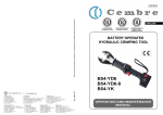
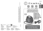
www.cembre.com
Cembre S.p.A.
Via Serenissima, 9
25135 Brescia (Italia)
Telefono: 030 36921
Telefax: 030 3365766
E-mail: [email protected]
www.cembre.it
Cembre España S.L.
Calle Verano, 6 y 8 - P.I. Las Monjas
28850 Torrejón de Ardoz - Madrid (España)
Teléfono: 91 4852580
Telefax: 91 4852581
E-mail: [email protected]
www.cembre.es
Cembre Ltd.
Dunton Park
Kingsbury Road, Curdworth - Sutton Coldfield
West Midlands B76 9EB (Great Britain)
Tel.: 01675 470440 - Fax: 01675 470220
E-mail: [email protected]
www.cembre.co.uk
Cembre AS
Fossnes Senter
N-3160 Stokke (Norway)
Phone: (47) 33361765
Telefax: (47) 33361766
E-mail: [email protected]
www.cembre.no
Cembre S.a.r.l.
22 Avenue Ferdinand de Lesseps
91420 Morangis (France)
Tél.: 01 60 49 11 90 - Fax: 01 60 49 29 10
B.P. 37 - 91421 Morangis Cédex
E-mail: [email protected]
www.cembre.fr
Cembre GmbH
Heidemannstraße 166
80939 München (Deutschland)
Telefon: 089/3580676
Telefax: 089/35806777
E-mail: [email protected]
www.cembre.de
cod. 6261243
This manual is the property of Cembre: any reproduction is forbidden without written permission.
Ce manuel est la proprieté de Cembre: toute reproduction est interdite sauf autorisation écrite.
Der Firma Cembre bleibt das Eigentumsrecht der Bedienungsanleitung vorbehalten.
Ohne vorherige schriftliche Genehmigung darf die Bedienungsanleitung weder vollständig noch teilweise vervielfältigt werden.
Este manual es propriedad de Cembre. Toda reproducción está prohibida sin autorización escrita.
Questo manuale è di proprietà della Cembre: ogni riproduzione é vietata se non autorizzata per scritto.
11 M 057
Cembre Inc.
Raritan Center Business Park
181 Fieldcrest Avenue
Edison, New Jersey 08837 (USA)
Tel.: (732) 225-7415 - Fax: (732) 225-7414
E-mail: [email protected]
www.cembreinc.com
ENGLISH
FRANÇAIS
DEUTSCH
ESPAÑOL
Certified Quality
Management System
Certified Environmental
Management System
Certified Occupational
Health & Safety
Management System
ITALIANO
BATTERY OPERATED HYDRAULIC CRIMPING TOOL
PRESSE HYDRAULIQUE SUR BATTERIE
HYDRAULISCHES AKKU-PRESSWERKZEUG
HERRAMIENTA HIDRAULICA DE COMPRESIÓN A BATERíA
UTENSILE OLEODINAMICO DA COMPRESSIONE A BATTERIA
B131-C
B131-CA
B131-C-KV
OPERATION AND MAINTENANCE MANUAL
NOTICE D’UTILISATION ET ENTRETIEN
BEDIENUNGSANLEITUNG
MANUAL DE USO Y MANTENIMIENTO
MANUALE D’USO E MANUTENZIONE
WARNING LABELS - ETIQUETTES SIGNALETIQUES - WARNSCHILDER ETIQUETAS DE ATENCION - ETICHETTE D’AVVERTENZA
MOD. CB1430H 14,4V - 3,0Ah Ni-MH
See page 37
Voir page 37
Siehe Seite 37
Vease página 37
Vedere pag. 37
Ni-MH
TG0659
Deutsch --------------------------------------------------------------------------------INFORMATION FÜR DEN BENUTZER gemäß der “Richtlinien 2002/95/EG und 2002/96/
EG in Bezug auf den reduzierten Gebrauch von gefährlichen Substanzen in elektrischen
und elektronischen Geräten, sowie auf die Abfallentsorgung”.
TG0356
!
▲
Das durchkreuzte Zeichen auf dem Mülleimer, welches auf dem Gerät oder seiner Verpackung
angebracht ist, zeigt an, dass das Produkt am Ende seiner Lebenszeit getrennt von den anderen
Abfällen entsorgt werden muss. Die getrennte Abfallsammlung des vorliegenden zu entsorgenden
Geräts wird vom Hersteller organisiert und verwaltet. Der Besitzer, der sich des Geräts entledigen
will, muss sich daher mit dem Hersteller in Verbindung setzen und das von ihm angenommene
System für die getrennte Sammlung des zu entsorgenden Geräts befolgen.
Eine angemessene getrennte Sammlung, damit das Gerät für das Recycling, die Behandlung
und die umweltfreundliche Entsorgung vorbereitet werden kann, trägt dazu bei, mögliche negative
Auswirkungen auf die Umwelt und auf den Gesundheitszustand zu vermeiden und begünstigt die
Wiederverwertung und das Recycling der Materialien des Geräts. Bei widerrechtlicher Entsorgung
des Produkts durch den Benutzer werden die vom Gesetz vorgesehen Verwaltungssanktionen
angewandt.
Español --------------------------------------------------------------------------------INFORME PARA LOS USUARIOS en los términos de las Directivas 2002/95/CE y 2002/96/
– Before using the tool, carefully read the instructions in this manual.
– Avant d’utiliser cet outil, lire attentivement les instructions de cette notice.
– Vor Inbetriebnahme unbedingt die Bedienungsanleitung durchlesen.
– Antes de utilizar la herramienta, leer atentamente las instrucciones contenidas en este manual.
– Prima di utilizzare l’utensile, leggere attentamente le istruzioni contenute in questo manuale.
– When operating the tool, keep hands away from the danger zone.
– Au cours du sertissage, tenir les mains éloignées de la zone de travail.
– Während des Verpressens nicht mit den Händen in den Pressbereich gelangen.
– Durante su utilización, mantenga las manos fuera de la zona de peligro.
– Durante l’utilizzo, mantenere le mani fuori dalla zona di pericolo.
–
–
–
–
–
Do not operate when dies are not in place.
Insérer les matrices avant d’actionner l’outil.
Nicht ohne Presseinsatzpaar betätigen.
No poner en presión sin matrices.
Non mandare in pressione l’utensile senza le matrici inserite.
CE, relativas a la reducción en el empleo de sustancias peligrosas en los equipos eléctricos y electrónicos, además de la eliminación de los desechos”.
El símbolo del contenedor de basura cruzado por un aspa que aparece en el equipo o sobre su embalaje indica que, al final de su ciclo de vida útil, el producto debe ser eliminado
independientemente de otros desechos.
La recogida selectiva del presente equipo, llegado al final de su ciclo de vida, es organizada y
manejada por el fabricante. El usuario que desee deshacerse del presente equipo deberá, por
lo tanto, contactar con el fabricante y seguir el sistema adoptado por el mismo para permitir
la recogida por separado del equipo que ha concluido su ciclo de vida. La adecuada recogida
selectiva, para el sucesivo envío del equipo dado de baja al reciclaje, al tratamiento y al saneamiento ambiental compatible, contribuye a evitar posibles efectos negativos sobre el medio ambiente y sobre la salud favoreciendo el reempleo y el reciclaje de los materiales que componen
el equipo. La eliminación abusiva del equipo por parte del propietario implica la aplicación de
las sanciones administrativas prevista por la legislación vigente.
Italiano ---------------------------------------------------------------------------------INFORMAZIONE AGLI UTENTI ai sensi dell’art. 13 del Decreto Legislativo 25 Luglio 2005, n.
151 “Attuazione delle Direttive 2002/95/CE e 2002/96/CE, relative alla riduzione dell’uso di
sostanze pericolose nelle apparecchiature elettriche ed elettroniche, nonché allo smaltimento dei rifiuti”.
– Do not short-circuit the batteries.
– Ne jamais court-circuiter les bornes d’une batterie.
– Schliessen Sie die Kontakte nicht kurz. Brandgefahr!
– No poner en cortocircuito las baterías.
– Mai mettere in corto circuito le batterie.
– Always recycle the batteries.
Do not discard batteries into domestic refuse or waste disposal.
– Recycler toujours les batteries.
Ne pas jeter de batteries dans une poubelle ou autre lieu non prévu à cet effet.
– Verbrauchte Akkus stets dem Recycling zuführen.
Verbrauchte Akkus nicht in den Hausmüll werfen.
– Reutilizar siempre las baterias.
No tirar las baterías al cubo de basura o lugar parecido.
– Riciclate sempre le batterie.
Non buttate le batterie fuori uso nei cestini della spazzatura o luoghi simili.
1
Il simbolo del cassonetto barrato riportato sull’apparecchiatura o sulla sua confezione indica che il
prodotto, alla fine della sua vita utile, deve essere raccolto separatamente dagli altri rifiuti.
La raccolta differenziata della presente apparecchiatura giunta a fine vita è organizzata e gestita
dal produttore. L’utente che vorrà disfarsi della presente apparecchiatura dovrà quindi contattare il
produttore e seguire il sistema che questo ha adottato per consentire la raccolta separata dell’apparecchiatura giunta a fine vita.
L’adeguata raccolta differenziata per l’avvio successivo dell’apparecchiatura dismessa al riciclaggio, al trattamento ed allo smaltimento ambientalmente compatibile contribuisce ad evitare possibili effetti negativi sull’ambiente e sulla salute e favorisce il reimpiego e/ il riciclo dei materiali di cui
è composta l’apparecchiatura.
Lo smaltimento abusivo del prodotto da parte del detentore comporta l’applicazione delle sanzioni
amministrative di cui all’articolo 50 e seguenti del D.Lg. n. 22/1997.
38
– Following information applies in member states of the
European Union:
TIPO
TYPE
– Les informations suivantes sont destinées aux pays
membres de l’Union Européenne:
FORZA
FORCE kN
B131-C
-
Tool type
Outil type
Werkzeug Typ
Herramienta tipo
Tipo di utensile
130
ANNO
YEAR
– Die folgenden Hinweise gelten für Mitglieder der Europäischen Union:
-
Force
Force
Kraft
Fuerza
Forza
-
Year
Année
Jahr
Año
Anno
Made in Italy
– Las siguientes informaciones conciernen a los estados miembros de la Unión Europea:
18
17
– Le seguenti informazioni riguardano gli stati membri
dell’Unione Europea:
16
English ---------------------------------------------------------------------------------USER INFORMATION in accordance with “Directives 2002/95/EC and 2002/96/EC regarding
the reduction of hazardous substances in electrical and electronic equipment, including the
disposal of waste”.
15
11
The ‘Not in the bin’ symbol above when shown on equipment or packaging means that the
equipment must, at the end of its life, be disposed of separately from other waste.
The separate waste collection of such equipment is organised and managed by the manufacturer.
Users wishing to dispose of such equipment must contact the manufacturer and follow the
prescribed guidelines for its separate collection. Appropriate waste separation, collection,
environmentally compatible treatment and disposal is intended to reduce harmful environmental
effects and promote the reuse and recycling of materials contained in the equipment. Unlawful
disposal of such equipment will be subject to the application of administrative sanctions
provided by current legislation.
25
Français --------------------------------------------------------------------------------INFORMATION POUR LES UTILISATEURS Aux termes des “Directives 2002/95/CE et
2002/96/CE relatives à la réduction de l’utilisation de substances dangereuses dans les
appareils électriques et électroniques ainsi qu’à l’élimination des déchets”.
Le symbole “poubelle barrée” apposé sur l’appareil ou sur son emballage indique que le produit,
à la fin de sa vie utile, doit être recueilli séparément des autres déchets.
La collecte sélective du présent appareil en fin de vie est organisée et gérée par le producteur.
L’utilisateur qui voudra se défaire du présent appareil devra par conséquent contacter le producteur
et suivre le système que celui-ci a adopté pour consentir la collecte séparée de l’appareil en fin
de vie.
La collecte sélective adéquate pour l’envoi successif de l’appareil destiné au recyclage, au
traitement et à l’élimination compatible avec l’environnement contribue à éviter les effets négatifs
possibles sur l’environnement et sur la santé et favorise la réutilisation ou le recyclage des matériaux
dont l’appareil est composé.
L’élimination abusive du produit par le détenteur comporte l’application des sanctions
administratives prévues par les lois en vigueur.
37
05
FIG. 1
OVERALL VIEW
VUE D’ENSEMBLE
GESAMTANSICHT
VISTA DEL CONJUNTO
VISTA D’ASSIEME
2
19
22
ENGLISH
BATTERY OPERATED HYDRAULIC CRIMPING TOOL
B131-C ; B131-CA ; B131-C-KV
!
▲
18
IMPORTANT INFORMATION FOR WORKING IN THE
PROXIMITY OF ENERGISED CONDUCTORS
- CERTAIN KV
VERSIONS OF
Cembre
19
20
TOOLS ARE PROVIDED WITH ADDITIONAL
COATINGS TO PROTECT THE OPERATOR AND TOOL AGAINST ACCIDENTAL BRUSH
CONTACT WITH ENERGISED CONDUCTORS.
21
- PROPER TRAINING TECHNIQUES AND PRACTICES SHOULD ALWAYS BE ADHERED TO
WHEN WORKING AROUND ENERGISED CONDUCTORS.
- ALWAYS
22
CONSULT YOUR COMPANY’S WORK RULES AND METHODS TO SELECT
SUITABLE TOOLING, RUBBER INSULATED GLOVES, SHROUDING AND OTHER PROTECTIVE EQUIPMENT.
23
- UNDER NO CIRCUMSTANCES SHOULD OPERATIVES RELY SOLELY ON THE INSULATING
PROPERTIES OF THE TOOLS ALONE WHEN WORKING AROUND ENERGISED CONDUCTORS.
24
- PRIOR TO USE PLEASE ENSURE THE TOOL AND SPECIFICALLY THE INSULATING PROTECTION HAVE NOT BE DAMAGED.
25
This hydraulic tool is powered by a 14.4V battery. The tool is quiet in operation with
minimal vibration, balanced for optimum control, with lightweight construction enabling it
to be held in one hand while positioning the connector with the other.
Operating and release buttons are integrated one in the other and mechanically interlocked
to prevent accidental operation.
Microprocessor control automatically stops the motor at the end of the crimp cycle, saving
energy and extending the life of the battery, whose residual energy level is automatically
displayed after each operation.
26
The part references “B131-C, B131-CA or B131-C-KV” include the following:
– Basic tool complete with battery and shoulder strap
– Spare battery
– Battery charger
– Steel carrying case “VAL P19”
28
3
36
ENGLISH
17
1. GENERAL CHARACTERISTICS
B131-C
TOOL TYPE:
16
B131-C-KV
B131-CA
suitable for installing electrical compression connectors
Application range:
for conductors up to 400 mm2 (800 MCM)
10
11
12
13
14
Crimping force
15
130 (14.6)
Rated operating pressure bar (psi):
Dimensions LxWxH
09
08
mm (inches):
Weight with battery
kg (lbs):
Motor
Volt DC:
Battery
Volt / Ah:
Battery charger supply
Volt / Hz:
External supply:
700 (10,000)
420 x 100 x 250 (16.5 x 3.9 x 9.8)
7,1 (15.6)
Recommended oil:
7,4 (16.3)
14.4
14.4 / 3.0 Li-Ion
14.4 / 3.0 Ni-MH
220 - 240 / 50 - 60
120 / 50 - 60
12 - 14.4 V DC
12 - 14.4 V DC
√
Fully insulated head:
E
07
kN (sh ton):
AGIP ARNICA 32 or SHELL TELLUS TX 32 or equivalent
Recommended oil for “KV” versions: AGIP ITE 360 or ESSO TRANSFORMER P60 or equivalent
Operating speed:
06
the tool has a twin speed operation and automatically
switches from a rapid advancing speed of the
ram to a slower more powerful crimping speed.
E
05
Operating temperature:
04
-15°C to +40°C (+5°F to +104°F)
2. INSTRUCTIONS FOR USE (Ref. to Figs. 1 and 2)
2.1) Preparation
03
02
the tool is equipped with a maximum pressure valve.
Safety:
The tool can be easily carried using either the handle or the shoulder strap (11) attached
to the rings (15 and 18).
With the tool in the rest position proceed as follows:
– Select the appropriate die set for the connector.
– Insert the die (91) into the upper seat of the tool head (05) until it is locked by die/head
retaining pin (06). To ease the die insertion, keep die/head release pin (10) depressed.
– Press the operating button (17) to advance the ram (14) 3÷4 mm and insert the die (90 )
into the seat on the head of ram (14) until it is locked by die/ram retaining pin (02). To
ease this operation, keep die/ram release pin (04) depressed.
– Insert the conductor in the connector.
– Position the connector between the dies and ensure the correct location of the crimp
points.
E-E
01
FIG. 5
LONG
GITUDINAL SECTION
COUPE LONGITUDINALE
SCHN
NITTZEICHNUNG
SECC
CION LONGITUDINAL
SEZIONE LONGITUDINALE
35
NEVER
PRESSURISE THE TOOL WITHOUT INSERTING THE DIES, AS THIS COULD
CAUSE DAMAGE TO THE HEAD AND THE PISTON.
4
ENGLISH
2.2) Die advancement
17
16
B131-C
B131-CA
(Ref. to Figs. 1 and 5)
Press the operating button (17) located on
the top of the pressure release button (16)
to activate the motor-pump and advance the
lower die. To halt the advancement, release
the operating button (17) and the motor will
cut out.
Make sure the dies are exactly positioned on the desired crimp points otherwise
re-open dies following instructions as per § 2.4 and reposition the connector.
2.3) Compression
For ease of operation, the tool head can rotate through 180°, allowing the operator to work
in the most comfortable position.
Warning: Do not attempt to turn the head when the hydraulic circuit is pressurised.
22
23
92
2.5) Head rotation
93
By pressing the pressure release button (16), the ram (14) will retract and open the dies.
12V ÷ 14.4V DC
2.4) Release of dies
19
– By keeping the operating button (17) pressed, the motor runs and the ram advances
until the two dies touch.
– It is recommended to continue pumping until the motor stops automatically.
2.6) Die replacement (Ref. to Fig. 2)
To replace dies proceed as follows:
– Upper die (91)
Take the die off its guide by pushing the die/head release pin (10).
Insert replacement die until secured by the die retaining pin (06).
– Lower die (90)
Take the die off its guide by pushing the die/ram release pin (04).
To facilitate this operation an advancement of the ram (14) by 3÷4 mm is suggested.
Insert replacement die into its guide until secured by the die/ram retaining pin (02).
5
FIG. 4
EXTERNAL SUPPLY (only for B131-C and B131-CA)
ALIMENTATION EXTERIEURE (seulement pour B131-C et B131-CA)
EXT. ENERGIEVERSORGUNG (Nur für B131-C und B131-CA)
ALIMENTACION EXTERNA (solamente para B131-C y B131-CA)
ALIMENTAZIONE ESTERNA (solo per B131-C e B131-CA)
34
ENGLISH
05
91
2.7) Battery status (Ref. to Fig. 1)
After releasing the operating button, the residual battery capacity is automatically displayed
for 5 seconds. The number of LEDs illuminated indicates the residual capacity:
8 leds illuminated: Fully charged
4 leds illuminated: 50 % capacity
1 led illuminated: Minimum charge
10
06
02
90
When replacing the battery press the two points marked with the word “PUSH” at the
same time, remove the flat battery from its housing and insert the new one.
~3
2.8) Power from an external source (only for B131-C/CA)
÷4
mm
14
04
FIG. 2
DIE REPLACEMENT
INSERTION DES MATRICES
EINRASTEN PRESSEINSÄTZE
INSERCION DE LAS MATRICES
INSERIMENTO MATRICI
Using the integral socket (23) the tool can be powered from a external power supply
(min. 20A) or vehicle battery (Ref. to Fig. 4).
Using the special connection cable type ESC 600, available as an optional accessory,
proceed as follows:
– Make sure the supply voltage is between 12 and 14,4 V DC.
– Connect the spring clips to the external supply ensuring correct polarity, red to positive
pole (+), black to negative pole.
– Remove the cap (22) from the socket (23) on the tool and insert connector (93), tightening
the bezel clockwise until it locks.
– When the work is finished, disconnect the cable (93) and replace the protective cap (20).
Should the poles be accidentally reversed, the tool will not be damaged but will operate using only the integral battery (19). For rectification, reverse the polarity of the spring clips.
WHEN USING AN EXTERNAL POWER SUPPLY, NEVER SHORT CIRCUIT THE METAL
VAL P 19
CONTACTS INSIDE THE BATTERY HOUSING. WE ADVISE LEAVING THE BATTERY (19)
IN ITS HOUSING AS IT WILL SUPPLY POWER IN PARALLEL WITH THE EXTERNAL SOURCE.
3. WARNING
THE TOOL IS UNSUITABLE FOR CONTINUOUS USE AND SHOULD BE ALLOWED TO
COOL DOWN FOLLOWING UNINTERRUPTED, SUCCESSIVE OPERATIONS; FOR INSTANCE,
HAVING EXHAUSTED A FULLY CHARGED BATTERY IN ONE SESSION, DELAY BATTERY
REPLACEMENT FOR A FEW MINUTES.
OBSERVE RECOMMENDED REST PERIODS ALSO WHEN USING AN EXTERNAL POWER
SUPPLY.
DO NOT ATTEMPT TO ROTATE THE HEAD WHEN THE HYDRAULIC CIRCUIT IS PRES-
FIG. 3
STORAGE
RANGEMENT
LAGERUNG
ALMACENAMIENTO
CUSTODIA
SURISED.
PROTECT THE TOOL FROM RAIN AND MOISTURE. WATER WILL DAMAGE THE TOOL
AND BATTERY. ELECTRO-HYDRAULIC TOOLS SHOULD NOT BE OPERATED IN POURING
RAIN OR UNDER WATER.
33
6
ITALIANO
ENGLISH
3.1) Using the battery charger
6. LISTA DEI COMPONENTI (Rif. a Fig. 5)
Carefully follow the instructions in the battery charger manual.
N° Codice Part.
3.2) General information on how to use batteries
In order to use the batteries correctly, please follow these rules:
– Use the battery until the automatic residual energy display still has 1-2 LEDs showing:
this means the battery is almost completely discharged and no loss in the life of the
battery has been caused.
– Be particularly careful when charging the new battery the first 2-3 times in order to be
certain of maximising the available energy level.
– Allow the battery to cool down to ambient temperature prior to recharging.
– Rest the battery charger for at least 15 minutes between charges.
4. MAINTENANCE
The tool is robust, completely sealed and requires very little daily maintenance.
Compliance with the following points should help to maintain the optimum performance
of the tool:
6522006
6620320
6760040
6620445
▲
6620440
6340540
6522006
6760160
▲
6000354
6100035
6900211
6620316
01
02
03
04
05
06
07
08
09
10
11
12
13
14
4.2) Storage (Ref. to Fig. 3)
When not in use, the tool should be stored and transported in the plastic case, to prevent
damage. The case is suitable for storing the tool, the accessories and up to 14 sets of dies.
Plastic case: “VAL P19” size: 542x412x197 mm (21.3x16.2x7.7 in.), weight: 3,2 kg (7 lbs).
Q.tà
1
1
1
1
1
1
1
1
1
1
1
1
1
1
N° Codice Part.
6040427
6000383
6000236
6040427
–
6800040
6720075
▲
–
6000310
6232243
–
6232006
15
16
17
18
19
20
21
22
23
24
25
26
28
DESCRIZIONE
Q.tà
ANELLO ATTACCO TRACOLLA
PULSANTE SBLOCCA PRESSIONE
PULSANTE DI COMANDO
ANELLO ATTACCO TRACOLLA
BATTERIA 14.4V
TAPPO SERBATOIO
SERBATOIO
TAPPO CONNETTORE (*)
CONNETTORE ALIM. EXT. (*)
MOTORE
ETICHETTA IND.CARICA (TG. 0443)
ETICHETTA UTENSILE
ETICHETTA AVVERTENZE (TG. 0356)
1
1
1
1
1
1
1
1
1
1
1
1
1
(*) Solo per le versioni B131-C e B131-CA.
4.1) Thorough cleaning
Dust, sand and dirt are a danger for any hydraulic device.
Every day, after use, the tool must be wiped with a clean cloth, taking care to remove any
residue, especially close to pivots and moveable parts.
DESCRIZIONE
MOLLA PISTONCINO
PISTONCINO FERMA MATRICE
SPINA ELASTICA ø 3x8
PISTONCINO SBLOC. MATRICE
GANCIO “C”
PISTONCINO FERMA MATRICE
GRANO M10x8
MOLLA PISTONCINO
SPINA ELASTICA ø 3x28
PISTONCINO SBLOC. MATRICE
TRACOLLA
CHIAVETTA
VITE M5x10
PISTONE
La garanzia decade qualora vengano utilizzate
parti di ricambio non originali Cembre .
▲ N° Codice
Part.
B131-C
B131-CA
05
10
22
6370213
6620460
6000411
B131-C-KV
6370232
6620245
Per ordinare parti di ricambio,specificare sempre
i seguenti punti:
- numero di codice del componente
- denominazione del componente
- tipo dell’utensile
- numero di matricola dell’utensile.
_______________________
4.3) Oil top up
Should it be required, top up the oil as follows (Ref. to Fig. 5):
– Remove the battery (19), place the tool in a vertical position and remove the filler cap
(20) located inside the battery housing, fill the reservoir (21) to the top; Replace the filler
cap (20).
Always use clean recommended oil, see § 1.
Do not use old or recycled oil.
Do not use hydraulic brake fluid.
5. RETURN TO Cembre FOR OVERHAUL
In the case of a breakdown contact our Area Agent who will advise you on the problem
and give you the necessary instructions on how to dispatch the tool to our nearest service
Centre; if possible, attach a copy of the Test Certificate supplied by Cembre together
with the tool or, if no other references are available, indicate the approximate purchase
date and the tool serial number.
7
Rumore Aereo (Direttiva 2006/42/CE, allegato 1, punto 1.7.4.2, lettera u)
– Il livello di pressione acustica continuo equivalente
ponderato A nel posto di lavoro LpA è pari a ................................................. 72,4 dB (A)
– Il valore massimo della pressione acustica istantanea
ponderata C nel posto di lavoro LpCPeak è ................................................... < 130 dB (C)
– Il livello di potenza acustica emessa dalla macchina
LWA è pari a................................................................................................... 83,1 dB (A)
Rischi dovuti alle vibrazioni (Direttiva 2006/42/CE, allegato 1, punto 2.2.1.1)
Rilievi condotti, secondo le indicazioni delle Norme UNI ENV 25349 e UNI EN 28662
parte 1a, in condizioni di utilizzo ampiamente rappresentative rispetto a quelle normalmente riscontrabili, attestano che il valore quadratico medio ponderato, in frequenza,
dell’accelerazione cui sono esposte le membra superiori, per ciascuno degli assi
biodinamici di riferimento, non supera i 2,5 m/sec2.
32
ITALIANO
ENGLISH
3.1) Utilizzo del caricabatterie
6. PARTS LIST (Ref. to Fig. 5)
Seguire attentamente le istruzioni dettagliate sul relativo manuale.
3.2) Informazioni di carattere generale sull’uso delle batterie
Per un uso corretto delle batterie, vi consigliamo di attenervi alle seguenti regole:
– Utilizzare la batteria fino a che la visualizzazione automatica dell’energia residua mostri
1-2 led; ciò corrisponde ad una situazione di scarica quasi completa della batteria, senza
peraltro che ne sia compromessa la durata di vita.
– Fare particolare attenzione alle prime 2 o 3 ricariche quando la batteria è nuova, per
assicurarsi il massimo della capacità disponibile.
– Al momento dell’estrazione dall’utensile, nel caso la batteria manifestasse un moderato
riscaldamento, aspettare che si raffreddi prima della ricarica.
– Lasciare riposare almeno 15 minuti il caricabatteria tra una ricarica e l’altra.
4. MANUTENZIONE
L’utensile è robusto, completamente sigillato e non richiede attenzioni particolari; per
ottenere un corretto funzionamento basterà osservare alcune semplici precauzioni:
Code N°
Item
6522006
6620320
6760040
6620445
▲
6620440
6340540
6522006
6760160
▲
6000354
6100035
6900211
6620316
01
02
03
04
05
06
07
08
09
10
11
12
13
14
4.2) Custodia (Rif. a Fig. 3)
Per proteggere l’utensile da urti accidentali e dalla polvere, quando non viene utilizzato, è
bene custodirlo nell’apposita valigetta in materiale plastico accuratamente chiusa.
Questa valigetta (tipo VAL P19), adatta al contenimento dell’utensile, della batteria di
riserva, del caricabatterie, della tracolla e di 14 coppie di matrici ad innesto semicircolare,
ha dimensioni 542x412x197 mm (21.3x16.2x7.7 in.) e pesa 3,2 kg (7 lbs).
4.3) Rabbocco dell’olio
Nel caso eccezionale in cui fosse necessario, procedere al rabbocco dell’olio nel seguente
modo (Rif. a Fig. 5):
– Togliere la batteria (19), porre l’utensile in posizione verticale, togliere il tappo (20) posto
all’interno del vano batteria, riempire raso il serbatoio (21) quindi rimontare il tappo.
Usare esclusivamente un tipo d’olio consigliato al § 1.
Mai usare olio rigenerato o usato.
E’ necessario che l’olio sia pulito.
5. RESA ALLA Cembre PER REVISIONE
In caso di guasto contattare il nostro Agente di Zona il quale vi consiglierà in merito e fornirà le istruzioni necessarie per l’invio dell’utensile alla nostra Sede; se possibile, allegare
copia del Certificato di Collaudo a suo tempo fornito dalla Cembre con l’utensile oppure,
in mancanza di altri riferimenti, indicare la data approssimativa di acquisto.
31
Qty
Code N°
Item
DESCRIPTION
Qty
1
1
1
1
1
1
1
1
1
1
1
1
1
1
6040427
6000383
6000236
6040427
–
6800040
6720075
▲
–
6000310
6232243
–
6232006
15
16
17
18
19
20
21
22
23
24
25
26
28
STRAP ANCHOR RING
PRESSURE RELEASE BUTTON
OPERATING BUTTON
STRAP ANCHOR RING
14.4V - BATTERY
RESERVOIR CAP
OIL RESERVOIR
SOCKET CAP (*)
SOCKET (*)
MOTOR
(TG. 0443) LABEL
TOOL LABEL
(TG. 0356) WARNING LABEL
1
1
1
1
1
1
1
1
1
1
1
1
1
(*) Only for B131-C and B131-CA.
4.1) Accurata pulizia
Tenere presente che la polvere, la sabbia e lo sporco rappresentano un pericolo per ogni
apparecchiatura oleodinamica. Dopo ogni giorno d’uso si deve ripulire l’utensile con uno
straccio pulito, avendo cura di eliminare lo sporco depositatosi su di esso, specialmente
vicino alle parti mobili.
DESCRIPTION
SPRING
DIE RAM RETAINER PIN
ø 3x8 ELASTIC PIN
DIE RAM RELEASE PIN
“C” HEAD
DIE HEAD RETAINER PIN
M10x8 GRUB SCREW
SPRING
ø 3x28 ELASTIC PIN
DIE HEAD RELEASE PIN
WRISTSTRAP
KEY
M5x10 SCREW
RAM
The guarantee is void if parts used are not
Cembre original ones .
▲ Code N°
Item
B131-C
B131-CA
05
10
22
6370213
6620460
6000411
B131-C-KV
6370232
6620245
When ordering spare parts always specify the following:
- code number of item
- name of item
- type of tool
- tool serial number.
_______________________
Acoustic Noise (Directive 2006/42/EC, annexe 1, point 1.7.4.2 letter u)
– The weighted continuous acoustic pressure level equivalent
A at the work place LpA is equal to ................................................................ 72,4 dB (A)
– The maximum value of the weighted acoustic displacement
pressure C at the work place LpCPeak is ....................................................... < 130 dB (C)
– The acoustic power level emitted by the machine
LWA is equal to .............................................................................................. 83,1 dB (A)
Risks due to vibration (Directive 2006/42/EC, annexe 1, point 2.2.1.1)
Tests carried out in compliance with the indications contained in UNI ENV 25349 and
UNI EN 28662 part 1st Standards, and under operating conditions much more severe than
those normally found, certify that the weighted root mean square in frequency of the
acceleration the upper limbs are exposed to for each biodynamic reference axis
does not exceed 2.5 m/sec2.
8
FRANÇAIS
ITALIANO
2.7) Autonomia della batteria (Rif. a Fig. 1)
Al rilascio del pulsante di comando, il livello di carica della batteria (19) é visualizzato
automaticamente per 5 secondi sull’ indicatore di carica (25), ciò permette di conoscere
immediatamente l’autonomia residua:
PRESSE HYDRAULIQUE SUR BATTERIE
TYPE B131-C ; B131-CA ; B131-C-KV
!
▲
INFORMATIONS IMPORTANTES POUR L’UTILISATION
A PROXIMITE DE CABLES SOUS TENSION
8 led accesi: massima autonomia
4 led accesi: autonomia al 50 %
1 led acceso: minima autonomia
- L‘OUTILS Cembre DE LA VRSION KV SONT EQUIPES D’UN REVETEMENT SUPLEMENTAIRE AFIN DE PROTEGER L’UTILISATEUR CONTRE TOUT CONTACT ACCIDENTEL
AVEC UN CABLE SOUS TENSION.
- LES TECHNIQUES APPROPRIEES ET LES REGLES DE SECURITE DOIVENT TOUJOURS
ETRE STRICTEMENT APPLIQUEES LORS D’UNE OPERATION SOUS TENSION.
- CONSULTER SYSTEMATIQUEMENT LES PROCEDURES DE TRAVAIL DE VOTRE SOCIETE
AFIN DE CHOISIR L’OUTILLAGE APPROPRIE, GANTS ISOLES OU TOUT AUTRES MATERIELS
DE PROTECTIONS.
- LES
UTILISATEURS NE DOIVENT EN AUCUN CAS COMPTER UNIQUEMENT SUR LES
PROPRIETES ISOLANTES DE L’OUTIL LORSQU’ILS TRAVAILLENT PRES DES CONDUCTEURS SOUS TENSION.
- AVANT CHAQUE UTILISATION ASSUREZ-VOUS QUE L’ISOLANT DE L’OUTIL N’EST PAS
ENDOMMAGE.
La presse hydraulique fonctionne sous une alimentation de 14.4V fournie par une batterie.
Il s’agit d’un outil léger, silencieux, dépourvu de vibrations, que l’opérateur peut manier
confortablement d’une seule main pendant tout le cycle de travail; l’autre main étant ainsi
libre de placer correctement le connecteur.
L’équilibrage des masse et le pivotement de la tête à 180° permettent de toujours l’utiliser
dans des conditions confortables. Les boutons d’actionnement et de décompression sont
interbloqués mécaniquement; le premier est intégré au second et est configuré pour éviter les mises en route accidentelles. Le cycle de travail est géré par un microprocesseur
qui coupe automatiquement l’alimentation du moteur en fin de sertissage pour limiter les
consommations d’énergie.
L’affichage du niveau de charge de la batterie, visible à la fin de chaque opération, permet
de connaître l’autonomie disponible.
La référence “B131-C, B131-CA ou B131-C-KV” désigne l’ensemble suivante:
– Outil de base avec batterie et bandoulière
– Batterie de rechange
– Chargeur de batterie
– Coffret de rangement métallique “VAL P19”
Per la sostituzione della batteria esaurita basterà premere contemporaneamente i due
punti indicati dalle scritte “PUSH”, estrarre la batteria scarica dalla sua sede ed inserire
a fondo quella carica.
2.8) Alimentazione da fonte esterna (solo per B131-C/CA)
L’utensile può essere attivato anche con un alimentatore (min. 20A) o batteria esterna
tramite il connettore (23) (Rif. a Fig. 4).
Utilizzando l’apposito cavo di collegamento tipo ESC 600, fornito come accessorio opzionale, procedere nel modo seguente:
– Verificare che la tensione di alimentazione sia compresa fra 12 e 14,4 V DC.
– Collegare il lato intestato con le pinze a molla all’alimentazione esterna rispettando la
polarità: la pinza rossa al polo positivo (+), la nera al polo negativo (–).
– Togliere il tappo (22) e collegare l’altro lato del cavo di collegamento (93) al connettore
(23) dell’utensile; serrare il connettore (92) ruotandone la ghiera in senso orario fino al
suo blocco.
– A lavoro ultimato scollegare il cavo di collegamento (93) e rimettere il tappo di protezione (22).
Nel caso di un inversione di polarità nel collegamento, l’utensile non subirà danni ma
continuerà a funzionare tramite la batteria (19) a bordo utensile, per ottenere il corretto
funzionamento basterà invertire le pinze a molla.
DURANTE L’ALIMENTAZIONE CON FONTE ESTERNA, MAI CORTOCIRCUITARE I CONTATTI METALLICI ALL’INTERNO DEL VANO BATTERIA, CONSIGLIAMO PER QUESTO DI
LASCIARE LA BATTERIA (19) NEL SUO ALLOGGIAMENTO, ESSA FORNIRÀ ENERGIA
IN PARALLELO ALLA FONTE ESTERNA.
3. AVVERTENZE
L’UTENSILE NON È ADATTO AD UN UTILIZZO CONTINUO; DOPO AVER ESEGUITO IL
NUMERO DI OPERAZIONI CONSECUTIVE CONSENTITE DA UNA BATTERIA COMPLETAMENTE CARICA, IN OCCASIONE DEL CAMBIO BATTERIA CONSIGLIAMO UN OPPORTUNO PERIODO DI PAUSA PER PERMETTERE IL RAFFREDDAMENTO DELL’UTENSILE.
OSSERVARE OPPORTUNI PERIODI DI PAUSA ANCHE UTILIZZANDO ALIMENTATORI
ESTERNI.
NON FORZARE LA TESTA TENTANDO DI RUOTARLA QUANDO L’UTENSILE È IN PRESSIONE.
PROTEGGERE L’UTENSILE DALLA PIOGGIA E DALL’UMIDITÀ. L’ACQUA POTREBBE
DANNEGGIARE L’UTENSILE E LA BATTERIA. GLI UTENSILI ELETTRO-OLEODINAMICI
NON DOVREBBERO ESSERE USATI SOTTO LA PIOGGIA O SOTTO ACQUA.
9
30
FRANÇAIS
ITALIANO
2.2) Accostamento delle matrici
(Rif. a Fig. 1 e 5)
Agendo su pulsante di comando (17) ricavato
all’interno del pulsante di rilascio pressione
(16), si avvia il gruppo motore-pompa ed inizia
l’avvicinamento delle matrici al connettore:
rilasciando il pulsante di comando (17) in
qualsiasi momento, si ha l’immediato arresto
sia del motore (24) sia del movimento del
pistone (14).
1. CARACTERISTIQUES GENERALES
17
B131-C
OUTIL TYPE:
16
B131-CA
B131-C-KV
conçue pour le sertissage des connecteurs jusqu’ à
Domaine d’application:
400 mm2 (800 MCM)
kN (sh ton):
Force de sertissage
Pression nominale
bar (psi):
Dimensions LxLxH
mm (inches):
Poids avec batterie
kg (lbs):
Assicurarsi che le matrici si trovino esattamente in corrispondenza con la zona da
comprimere; in caso contrario riaprirle seguendo le istruzioni del § 2.4 e riposizionare il connettore.
Moteur à courant continu
Volt DC:
Batterie
Volt / Ah:
Chargeur de batterie
Volt / Hz:
2.3) Compressione
Alimentation extérieure:
– Mantenendo premuto il pulsante di comando(17) il motore continua a funzionare:
il pistone (14) avanzerà progressivamente fino a portare le matrici in battuta tra loro.
– Consigliamo comunque di azionare il motore fino al suo arresto automatico.
Tête complètement isolée:
2.4) Sblocco delle matrici
Huile recommandée:
Attenzione: non forzare la testa tentando di ruotarla quando l’utensile é in pressione.
2.6) Cambio delle matrici (Rif. a Fig. 2)
Per effettuare il cambio delle matrici operare come segue:
– Matrice superiore (91)
Sfilare la matrice dalle sue guide tenendo premuto il pistoncino di sblocco (10) in modo
da annullare l’azione di ritenuta del pistoncino (06) e inserire la nuova matrice nelle guide
fino al suo bloccaggio.
–Matrice inferiore (90)
Sfilare la matrice dalle sue guide tenendo premuto il pistoncino di sblocco (04) in modo da
annullare l’azione di ritenuta del pistoncino (02) e inserire la nuova matrice nelle guide
fino al suo bloccaggio.
Si consiglia di far avanzare di 3÷4 mm il pistone (14) per facilitare l’operazione.
29
7,1 (15.6)
7,4 (16.3)
14.4
14.4 / 3.0 Li-Ion
14.4 / 3.0 Ni-MH
220 - 240 / 50 - 60
120 / 50 - 60
12 - 14.4 V DC
12 - 14.4 V DC
√
AGIP ARNICA 32 ou SHELL TELLUS TX 32 ou équivalents
d’approche des matrices,
à la vitesse lente de montée en pression.
Sécurité:
La testa dell’utensile può ruotare di 180° rispetto al corpo, permettendo così all’operatore
di eseguire il lavoro nella posizione più agevole.
700 (10,000)
420 x 100 x 250 (16.5 x 3.9 x 9.8)
Huile recommandée pour versions “KV”: AGIP ITE 360 ou ESSO TRANSFORMER P60 ou équivalents
Avance rapide:
l’outil passe automatiquement de la vitesse rapide
Premendo il pulsante di rilascio pressione(16), si otterrà il ritorno del pistone (14) con
conseguente apertura delle matrici.
2.5) Rotazione della testa
130 (14.6)
Température de fonctionnement:
l’outil est équipé d’une valve de surpression.
-15°C à +40°C (+5°F à +104°F)
2. INSTRUCTIONS D’UTILISATION (Voir Fig. 1 et 2)
2.1) Mise en service
L’outil peut être transporté facilement grâce à sa poignée et à la bandoulière (11) accrochée par les anneaux (15 et 18).
Avec l’outil en position repos, procéder de la façon suivante:
– Choisir la matrice en fonction du sertissage à réaliser.
– Insérer la matrice (91) dans le guide supérieur de la tête (05) de l’outil jusqu’à son ver
rouillage par l’axe (06). Cette opération n’est possible qu’en appuyant sur l’axe de dé
blocage (10).
– Insérer la matrice (90) dans le guide du piston (14) de l’outil jusqu’à son verrouillage
par l’axe
(02). Cette opération n’est possible qu’en appuyant sur l’axe de déblocage (04).
– Insérer le conducteur dans le connecteur.
– Positionner ce dernier dans le tête en faisant coïncider la zone de sertissage avec les
empreintes des matrices.
NE JAMAIS METTRE L’OUTIL SOUS PRESSION SANS LES MATRICES INSEREES,
CELA POURRAIT ENDOMMAGER LES SIEGES DE LA TETE ET DU PISTON.
10
FRANÇAIS
ITALIANO
2.2) Avance des matrices
(Voir Fig. 1 et 5)
Appuyer sur le bouton d’actionnement (17)
placé à l’intérieur du bouton de décompression
(16) pour mettre en marche le groupe moteurpompe; les matrices commencent alors à se
rapprocher du connecteur. Le bouton d’actionnement (17) relâché, le moteur et l’avance des
matrices cessent immédiatement.
1. CARATTERISTICHE GENERALI
17
B131-C
UTENSILE TIPO:
16
B131-C-KV
B131-CA
adatto all’installazione di connettori elettrici a compres-
Campo di applicazione:
sione per conduttori in genere fino a 400 mm2 (800 MCM)
kN (sh ton):
Forza sviluppata
130 (14.6)
Pressione nom. di eserciziobar (psi):
Dimensioni LxLxA
mm (inches):
Peso con batteria
kg (lbs):
700 (10,000)
420 x 100 x 250 (16.5 x 3.9 x 9.8)
7,4 (16.3)
7,1 (15.6)
S’assurer que les matrices sont bien positionées sur la zone à sertir. Dans le cas
contraire, les desserrer en suivant les instructions du § 2.4 et repositionner le
connecteur.
Motore
Volt DC:
Batteria
Volt / Ah:
14.4 / 3.0 Li-Ion
14.4 / 3.0 Ni-MH
Alim. caricabatteria
Volt / Hz:
220 - 240 / 50 - 60
120 / 50 - 60
2.3) Sertissage
Alimentazione esterna:
– En maintenant pressé le bouton d’actionnement (17), on maintient la rotation du moteur;
le piston (14) avance progressivement jusqu’à ce que les matrices arrivent en butée
l’une contre l’autre.
– Nous recommandons en tout cas d’actionner le moteur jusqu’à son arrêt automatique.
Testa totalmente isolata:
Olio consigliato:
Olio consigliato per versioni “KV”:
Velocità di avanzamento:
14.4
12 - 14.4 V DC
12 - 14.4 V DC
√
AGIP ARNICA 32 o SHELL TELLUS TX 32 o equivalenti
AGIP ITE 360 o ESSO TRANSFORMER P60 o equivalenti
sono due: una rapida di avvicinamento delle matrici
ed una più lenta di compressione.
2.4) Réouverture des matrices
En appuyant à fond sur le bouton de décompression (16), on provoque le retour du piston
(14) et par conséquent l’ouverture des matrices.
Sicurezza:
2.5) Rotation de la tête
Temperatura di funzionamento:
La tête de l’outil pivote de 180° par rapport au corps, permettant à l’utilisateur de travailler
dans la meilleure position.
Attention: ne pas forcer la rotation de la tête, lorsque le circuit hydraulique est
sous pression.
2.6) Changement des matrices (Voir Fig. 2)
Pour changer les matrices, procéder de la façon suivante;
– Matrice supérieure (91)
Retirer la matrice en poussant l’axe de déblocage matrice (10).
Insérer la nouvelle matrice.
– Matrice inférieure (90)
Retirer la matrice en poussant l’axe de déblocage matrice (04).
Insérer la nouvelle matrice dans ses guides jusqu’à son blocage par l’axe de verrouillage
matrice (02). Cette opération est facilitée par l’avancement de 3-4 mm du piston (14).
La commutazione da una all’altra é automatica.
-15°C a +40°C (+5°F a +104°F)
2. ISTRUZIONI PER L’USO (Rif. a Fig. 1 e 2)
2.1) Preparazione
L’utensile può essere trasportato agevolmente tramite l’impugnatura o la tracolla (11)
fissata agli anelli (15 e 18).
Con l’utensile in posizione di riposo operare come segue:
– Scegliere la coppia di matrici adatta alla connessione da effettuare.
– Inserire la matrice (91) nelle guide superiori della testa (05) dell’utensile fino al suo bloccaggio col pistoncino (06); per facilitare l’inserimento della matrice tenere premuto il pistoncino (10).
– Inserire l’altra matrice (90) nelle guide ricavate sulla testa del pistone (14) fino al suo
bloccaggio col pistoncino (02). Per facilitare l’inserimento della matrice tenere premuto
il pistoncino (04).
– Infilare il conduttore nel connettore.
– Posizionare quest’ultimo fra le due matrici allineando la zona da comprimere con l’impronta delle matrici stesse.
11
l’utensile è munito di valvola di massima pressione.
MAI METTERE IN PRESSIONE L’UTENSILE SENZA LE MATRICI INSERITE, CIÒ POTREBBE
CAUSARE IL DANNEGGIAMENTO DELLE SEDI DELLA TESTA E DEL PISTONE.
28
ITALIANO
FRANÇAIS
UTENSILE OLEODINAMICO DA COMPRESSIONE
A BATTERIA TIPO B131-C ; B131-CA ; B131-C-KV
!
▲
INFORMAZIONI IMPORTANTI PER L’UTILIZZO IN
PROSSIMITÁ DI CONDUTTORI IN TENSIONE
2.7) Autonomie de la batterie (Voir Fig. 1)
Au moment de relâcher le bouton de commande, le niveau de charge de la batterie (19)
s’affiche automatiquement pendant 5 secondes sur l’indicateur de charge (25), ce qui
permet de connaître immédiatement l’autonomie restante:
8 led allumées: autonomie maximale
4 led allumées: autonomie à 50 %
1 led allumée: autonomie minimale
- LE VERSIONI KV DEGLI UTENSILI Cembre SONO PROVVISTE DI UN RIVESTIMENTO
AGGIUNTIVO PER PROTEGGERE L’OPERATORE E L’UTENSILE DA ACCIDENTALI CON
TATTI CON CONDUTTORI IN TENSIONE.
Pour le remplacement de la batterie épuisée, il suffira de presser en même temps les
deux points indiqués par la mention “PUSH”, extraire la batterie déchargée de son siège
et y introduire celle qui est chargée.
2.8) Alimentation à partir d’une source extérieure (seulement pour B131-C/CA)
- QUALORA
SI DOVESSE LAVORARE IN PRESENZA DI CAVI IN TENSIONE BISOGNERÀ
PRIMA SOTTOPORSI AD UN’ADEGUATO ADDESTRAMENTO TECNICO E PRATICO.
- DOVRANNO SEMPRE ESSERE SEGUITE LE REGOLE E LE MODALITÀ PREVISTE DALLA
VOSTRA AZIENDA PER LA SCELTA DI ATTREZZATURA ADEGUATA, DI GUANTI ISOLATI
IN GOMMA, MASCHERE ED ALTRI DISPOSITIVI DI PROTEZIONE.
- IN
NESSUN CASO, L’OPERATORE DOVRÀ AFFIDARSI ESCLUSIVAMENTE ALLE PRO-
PRIETÀ ISOLANTI DEGLI UTENSILI, QUALORA SI TROVI A LAVORARE NELL’AREA DI
CONDUTTORI IN TENSIONE.
- PRIMA
DELL’UTILIZZO É NECESSARIO ACCERTARSI SEMPRE CHE L’UTENSILE E LA
SUA PROTEZIONE ISOLANTE NON SIANO DANNEGGIATI.
L’outil peut être alimenté par une alimentation extérieure (20A mini) raccordée au connecteur (23) (Voir Fig. 4).
En utilisant le câble type ESC 600 de connexion correspondant fourni en option, procéder
de la façon suivante:
– Vérifier que la tension d’alimentation est comprise entre 12 et 14,4 Volt DC.
– Connecter le côté avec les pinces à ressort d’alimentation externe en respectant la
polarité: la pince rouge avec le pôle positif (+), la noire avec le pôle négatif (–).
– Enlever le capuchon (22) et connecter l’autre côté du câble de connexion (93) avec le
connecteur (23) de l’outil; serrer le connecteur (92) en tournant la vis des le sens horaire
jusqu’à son blocage.
– Une fois le travail terminé, déconnecter le câble de connexion (93) et remettre le capuchon de protection (22).
Dans le cas d’une inversion de la polarité dans la connexion, l’outil ne subira pas de dommages mais il continuera à fonctionner au moyen de la batterie (19) qui est placée à bord
de l’outil; pour obtenir le fonctionnement correct, il suffira d’inverser les pinces à ressort.
PENDANT L’ALIMENTATION À PARTIR D’UNE SOURCE EXTÉRIEURE, NE JAMAIS COURT-
CIRCUITER LES CONTACTS METALLIQUES A L’INTÉRIEUR DE L’ESPACE DE LA BATTERIE; NOUS CONSEILLONS DONC DE LAISSER LA BATTERIE (19) DANS SON LOGEMENT, ELLE FOURNIRA DE L’ÉNERGIE PARALLÈLEMENT À LA SOURCE EXTÉRIEURE.
L’utensile oleodinamico é alimentato tramite batteria a 14.4V; si tratta di un utensile leggero, silenzioso, praticamente privo di vibrazioni; grazie all’equilibratura delle masse ed
alla testa ruotabile di 180° risulta estremamente versatile e maneggevole. L’operatore può
agevolmente azionare l’utensile per tutto il ciclo operativo con una sola mano, mentre con
l’altra può mantenere il corretto posizionamento del connettore. I pulsanti di azionamento e
rilascio sono meccanicamente interbloccati; il primo integrato nel secondo e sagomato in
modo da evitare azionamenti accidentali. Il ciclo di lavoro é gestito da un microprocessore
che provvede automaticamente allo spegnimento del motore a fine compressione in modo
da limitare il consumo energetico.
La visualizzazione automatica del livello di carica della batteria dopo ogni operazione,
permette di conoscere immediatamente l’autonomia residua.
Con la sigla “B131-C, B131-CA o B131-C-KV” si identifica l’assieme formato da:
– Utensile base completo di batteria e tracolla
– n° 1 batteria di riserva
– n° 1 caricabatterie
– n° 1 cassetta metallica di contenimento tipo “VAL P19”
27
3. PRECAUTIONS
L’OUTIL N’EST PAS CONÇU POUR UNE UTILISATION EN CONTINU; APRÈS AVOIR
EFFECTUÉ UNE QUANTITÉ D'OPÉRATIONS CONSÉCUTIVES À PARTIR D’UNE BATTERIE
COMPLÈTEMENT CHARGÉE, AU MOMENT DU REMPLACEMENT DE LA BATTERIE, NOUS
SUGGÉRONS D’OBSERVER UNE PÉRIODE D’ARRÊT POUR PERMETTRE LE REFROIDISSEMENT DE L’OUTIL.
LAISSER REPOSER L’OUTIL MÊME EN CAS D’UTILISATION D’UN ALIMENTATEUR DE
RÉSEAU.
NE PAS FORCER LA ROTATION DE LA TÊTE, LORSQUE LE CIRCUIT HYDRAULIQUE
EST SOUS PRESSION.
PROTÉGER L’OUTIL DE LA PLUIE ET DE L’HUMIDITÉ. L’EAU POURRAIT ENDOMMAGER
L’OUTIL ET LA BATTERIE LES OUTILS HYDRO-ELECTRIQUE NE DEVRAIENT PAS ÊTRE
UTILISÉS SOUS LA PLUIEET SOUS L’EAU.
12
ESPAÑOL
FRANÇAIS
3.1) Utilisation du chargeur de batterie
6. LISTA DE COMPONENTES (Ref. Fig. 5)
Suivre attentivement les instructions indiquées sur le manuel.
N° Código Elemento
3.2) Informations de caractère général sur l’utilisation des batteries
Pour un usage normal de la batterie, nous vous conseillons d’observer les règles suivantes:
– Utiliser la batterie jusqu’au moment où l’affichage automatique de l’énergie restante
affiche 1-2 led; cela correspond à une situation de décharge presque complète sans
toutefois compromettre leur durée.
– Faire particulièrement attention aux 2-3 premières recharges quand la batterie est neuve,
pour assurer le maximum de sa capacité disponible.
– Au moment de son extraction de l’outil, si la batterie montre un échauffement modéré,
attendre le refroidissement avant de la recharger.
– Laisser reposer le chargeur de batterie au moins 15 minutes entre les recharges.
4. ENTRETIEN
Cet outil est robuste,complètement scellé et ne nécessite aucune préoccupation ou entretien particulier.
Les recommandations qui suivent sont néanmoins souhaitables pour assurer une longévité
optimum:
6522006
6620320
6760040
6620445
▲
6620440
6340540
6522006
6760160
▲
6000354
6100035
6900211
6620316
01
02
03
04
05
06
07
08
09
10
11
12
13
14
DESCRIPCION
MUELLE
PISTONCILLO FIJA-MATRIZ
PASADOR ø 3x8
PISTONCILLO DESBLOQUEADOR
CABEZA “C”
PISTONCILLO FIJA-MATRIZ
TORNILLO M10X8
MUELLE
PASADOR ø 3x28
PISTONCILLO DESBLOQUEADOR
CORREA DE TRANSPORTE
TOPE
TORNILLO M5X10
PISTON
C.dad N° Código Elemento
DESCRIPCION
C.dad
6040427
6000383
6000236
6040427
–
6800040
6720075
▲
–
6000310
6232243
–
6232006
ANILLO UNIÓN CORREA
PULSADOR DESBLOQUEO PRESIÓN
PULSADOR DE ACCIONAMIENTO
ANILLO UNIÓN CORREA
BATERIA 14.4V
TAPON DEPOSITO DE ACEITE
DEPOSITO DE ACEITE
TAPON CONECTOR (*)
CONECTOR ALIMENT.EXT. (*)
MOTOR
ETIQUETA (TG. 0443)
ETIQUETA HERRAMIENTA
ETIQUETA DE ATENC. (TG. 0356)
1
1
1
1
1
1
1
1
1
1
1
1
1
1
1
1
1
1
1
1
1
1
1
1
1
1
1
15
16
17
18
19
20
21
22
23
24
25
26
28
(*) Solamente para B131-C y B131-CA.
La garantía pierde eficacia si se utilizan piezas de
repuesto distintas de las originales Cembre.
▲ N° Código
4.1) Nettoyage élémentaire
Veiller à protéger l’outil de la poussière, du sable et de la boue qui sont un danger à tout
système hydraulique. Chaque jour après utilisation, l’outil doit être nettoyé à l’aide d’un
chiffon propre, tout particulièrement aux endroits de pièces mobiles.
4.2) Rangement (Voir Fig. 3)
Au repos, pour protéger l’outil des coups accidentels et de la poussière, il convient de le
ranger dans le coffret en plastique. Ce coffret (type VAL P19), adapté pour contenir l’outil,
ses accessoires et 14 paires de matrices semi-circulaire a comme dimensions 542x412x197
mm (21.3x16.2x7.7 in.) et un poids de 3,2 kg (7 lbs).
4.3) Complément d’huile
Dans le cas exceptionnel où cela serait nécessaire de rajouter de l’huile, procéder de la
façon suivante (Voir Fig. 5):
– Enlever la batterie (19), mettre l’outil en position verticale, enlever le bouchon (20) situé
à l’intérieur de l’espace de la batterie, remplir le réservoir (21), remettre le bouchon.
Utiliser exclusivement un type d’huile mentionné au § 1.
Ne jamais utiliser d’huile usagée ou recyclée.
Il est indispensable que l’huile soit neuve.
5. ENVOI EN REVISION A Cembre
En cas de dysfonctionnement de l’appareil, merci de vous adresser à notre Agent Régional
qui vous conseillera et le cas échéant vous donnera les instructions nécessaires pour
envoyer l’outil à notre Centre de Service le plus proche. Dans ce cas, joindre une copie
du Certificat d’Essai livré par Cembre avec l’outil ou, à défaut d’autres éléments de référence, indiquer la date d’achat approximative et numéro de série.
13
Elemento
B131-C
B131-CA
05
10
22
6370213
6620460
6000411
B131-C-KV
6370232
6620245
Al pedir piezas de repuesto, indicar siempre los
elementos siguientes:
- número de código del elemento
- descripción del elemento
- tipo de herramienta
- número de serie de la herramienta
_______________________
Nivel sonoro aéreo (Directiva 2006/42/CE, anexo 1, punto 1.7.4.2, letra u)
– El nivel de presión acústica contínua equivalente
ponderado A en el puesto de trabajo LpA es de ............................................ 72,4 dB (A)
– El nivel máximo de la presión acústica instantánea
ponderada C en el puesto de trabajo LpCPeak es de ....................................< 130 dB (C)
– El nivel de potencia acústica emitida por la máquina
LWA es igual a................................................................................................ 83,1 dB (A)
Riesgos debidos a las vibraciones (Directiva 2006/42/CE, anexo 1, punto 2.2.1.1)
Medidas realizadas según las indicaciones de las Normas UNI ENV 25349 y UNI EN 28662
parte 1a, en condiciones de utilización ampliamente representativas respecto a las que se
encuentran normalmente, atestan que el valor cuadrático medio ponderado en frecuencia, de la aceleración a la que están expuestos los miembros superiores para cada eje
biodinámico de referencia, no supera los 2,5 m/sec2.
26
ESPAÑOL
FRANÇAIS
3.1) Utilización del cargador de batería
6. PIECES DETACHEES (Voir Fig. 5)
Seguir atentamente las instrucciones detalladas en el manual correspondiente.
3.2) Informaciones de carácter general sobre la utilización de las baterías
Para un uso correcto de las baterías, les aconsejamos atenerse a las siguientes reglas:
– Utilizar la batería hasta que la visualización automática de la energía restante muestre
1-2 led; esto corresponde a una situación de descarga casi completa de la batería, sin
que por otra parte la duración de su vida quede comprometida.
– Estar particularmente atento a las 2-3 primeras recargas cuando la batería está nueva,
para asegurarse el máximo de la capacidad disponible.
– En el momento de la extracción de la herramienta, en caso de que la batería manifestase
cierto calentamiento, esperar a que se enfríe antes de la recarga.
– Dejar reposar el cargador de batería por lo menos 15 minutos entre una recarga y otra.
4. MANTENIMIENTO
Esta herramienta es robusta, completamente precintada y no requiere cuidados especiales
para obtener un funcionamiento correcto, bastará tener algunas precauciones sencillas:
N° Code
Pièce
DÉNOMINATION
Q.té
N° Code
Pièce
DÉNOMINATION
Q.té
6522006
6620320
6760040
6620445
▲
6620440
6340540
6522006
6760160
▲
6000354
6100035
6900211
6620316
01
02
03
04
05
06
07
08
09
10
11
12
13
14
RESSORT
AXE DE VERROUILL. MATRICE
FICHE ø 3x8
AXE DE DEBLOQ. MATRICE
CHAPE EN "C"
AXE DE VERROUILL. MATRICE
VIS SANS TETE M10X8
RESSORT
FICHE ø 3x28
AXE DE DEBLOQ. MATRICE
BANDOULIERE
CLAVETTE
VIS M5X10
PISTON
1
1
1
1
1
1
1
1
1
1
1
1
1
1
6040427
6000383
6000236
6040427
–
6800040
6720075
▲
–
6000310
6232243
–
6232006
15
16
17
18
19
20
21
22
23
24
25
26
28
ANNEAU DE FIXAT. BANDOULIERE
BOUTON DE DECOMPRESSION
BOUTON D'ACTIONNEMENT
ANNEAU DE FIXAT. BANDOULIERE
BATTERIE 14.4V
BOUCHON DU RESERVOIR
RESERVOIR
CAPUCHONCONNECTEUR (*)
CONNECTEUR SOURCE EXT. (*)
MOTEUR
ETIQUETTE (TG. 0443)
ETIQUETTE OUTIL
ETIQUETTE SIGNALET. (TG. 0356)
1
1
1
1
1
1
1
1
1
1
1
1
1
(*) Soulement pour B131-C et B131-CA.
4.1) Limpieza adecuada
Tenga presente que el polvo, la arena y la suciedad en general, rapresentan un peligro
para toda herramienta hidráulica. Tras cada día de uso, se debe limpiar la herramienta
con un trapo limpio, teniendo cuidado de eliminar la suciedad depositada, especialmente
junto a las partes móviles.
Pièce
B131-C
B131-CA
05
10
22
6370213
6620460
6000411
4.2) Almacenamiento (Ref. Fig. 3)
Para proteger la herramienta de golpes accidentales y del polvo cuando no se va a utilizar,
es conveniente guardarla cerrada en su estuche de plástico de cierre hermético.
Dicho estuche (tipo VAL P19) de dimensiones 542x412x197 mm (21.3x16.2x7.7 in.),
pesa 3,2 kg (7 lbs).
Es apropriada para almacenar la herramienta, los accesorios, además de 14 juegos de
matrices con canal semicircular.
La garantie perd tout effet en cas d’emploi de
pièces détachées différentes des pièces d’origine
Cembre.
▲ N° Code
B131-C-KV
6370232
6620245
Lors de la commande de pièces détachées, prière
veuillez indiquer toujours les éléments suivants:
- numéro de code article de la pièce
- dénomination de la pièce
- type d’outil
- numéro de série de l’outil
_____________________
4.3) Rellenado de aceite
En el caso excepcional en el cual fuese necesario, rellenar de aceite de la manera siguiente (Ref. Fig. 5):
– Quitar la batería (19), colocar la herramienta en posición vertical, quitar el tapón (20)
situado en el interior del espacio de la batería, llenar raso el depósito (21), entonces
volver a poner el tapón.
Use exclusivamente uno de los tipos de aceite recomendados en el Epig. 1.
No use nunca aceite usado.
Debe ser aceite limpio.
5. DEVOLUCION A Cembre PARA REVISIONES
En caso de fallo de la herramienta, contactar con nuestro Agente de Zona quien les aconsejará y eventualmente les facilitará las instrucciones necesarias para remitir la herramienta
a nuestro centro de servicio más cercano. En tal caso, adjuntar a ser posible una copia
del Certificado de Ensayo entregado en su día por Cembre con la herramienta o a falta de
otro elemento de referencia indicar la fecha de compra aproximada y el número de serie.
25
Pression sonore aérienne (Directive 2006/42/CE, annexe 1, point 1.7.4.2, lettre u)
– Le niveau de pression sonore continue équivalente
pondérée A sur le poste de travail LpA est .................................................... 72,4 dB (A)
– Le niveau de pression sonore instantanée pondérée
C sur le poste de travail LpCPeak est ............................................................. < 130 dB (C)
– Le niveau de puissance acoustique dégagée par la
machine LWA est............................................................................................ 83,1 dB (A)
Risques dérivés des vibrations (Directive 2006/42/CE, annexe 1, point 2.2.1.1)
Des relevés réalisés suivant les indications des Normes UNI ENV 25349 et UNI EN 28662
partie 1a, dans des conditions de service largement représentatives des conditions d’emploi
normales témoignent que la valeur quadratique moyenne pondérée en fréquence de
l’accélération à laquelle sont exposés les membres supérieurs pour chaque axe
biodynamique de référence ne dépasse pas les 2,5 m/sec2.
14
ESPAÑOL
DEUTSCH
2.7) Autonomía de la batería (Ref. Fig. 1)
Al soltar el botón de mando, el nivel de carga de la batería (19) es visualizado automáticamente durante 5 segundos sobre el indicador de carga (25), esto permite conocer
inmediatamente la autonomía restante:
HYDRAULISCHES AKKU-PRESSWERKZEUG
TYP B131-C ; B131-CA ; B131-C-KV
!
▲
WICHTIGE HINWEISE BEI TÄTIGKEITEN IN DER NÄHE
VON UNTER SPANNUNG STEHENDEN TEILEN
8 led encendidos: autonomía máxima
4 led encendidos: autonomía al 50 %
1 led encendido: autonomía mínima
- EINIGE ISOLIERTE Cembre-WERKZEUGE SIND MIT ZUSÄTZLICHEN SCHUTZMASSNAH
MEN VERSEHEN, UM DEN MONTEUR UND DAS WERKZEUG GEGEN UNGEWOLL TES
BERÜHREN GEGEN UNTER SPANNUNG STEHENDEN LEITERN ZU SCHÜTZEN.
Para el reemplazamiento de la batería bastará con pulsar contemporáneamente los dos
puntos indicados por los letreros "PUSH", sacar la batería descargada de su alojamiento
e introducir a fondo la que está cargada.
2.8) Alimentación desde fuente externa (solamente para B 131-C/CA)
- IMMER MIT DEM VERANTWORTLICHEN ENTSCHEIDEN, WELCHES DIE RICHTIGEN
WERKZEUGE SIND, SOWIE DIE ARBEITSMETHODE BESPRECHEN UND WELCHE
SICHERHEITSMASSNAHMEN VORGENOMMEN WERDEN SOLLEN Z.B.
GUMMIHANDSCHUHE, ISOLIERTE ABDECKUNGEN UND ANDERE SCHUTZAUSRÜSTUNGEN.
- DIE ANLAGE MUSS STÄNDIG BEOBACHTET WERDEN, WENN AN UNTER SPANNUNG
STEHENDEN LEITERN GEARBEITET WIRD.
DER MONTEUR DARF SICH NICHT NUR AUF DEN ISOLATIONSSCHUTZ DE WERKZEUGES
VERLASSEN.
- DAS WERKZEUG IST VOR DEM EINSATZ AUF BESCHÄDIGUNGEN ZU KONTROLLIEREN.
DABEI IST AUF DEN ISOLIERSCHUTZ ZU ACHTEN.
Die Akkupresse wird von einem Akku mit 14.4V versorgt. Sowohl die Laufruhe und das
Fehlen jeglicher Vibrationen erlauben dem Anwender das Gerät während des gesamten
Arbeitsganges mit einer Hand zu bedienen. Mit der anderen Hand kann der Verbinder
oder Kabelschuh in der korrekten Position gehalten werden.
Durch die günstige Gewichtsverteilung und den um 180° drehbaren Kopf ist das Gerät
extrem vielseitig und leicht zu handhaben. Der Start- und der Druckablaßhebel sind in
einem Knopf enthalten, lassen sich aber nur getrennt voneinander betätigen. Er ist so
geformt, daß eine ungewollte Betätigung nicht möglich ist. Der Arbeitsvorgang wird von
einem Chip gesteuert, der zur Einschränkung des Energieverbrauchs den Motor nach der
Verpressung automatisch abschaltet.
Die automatische Anzeige des Batterieladezustandes nach jedem Arbeitsgang ermöglicht
außerdem die ständige Kontrolle der verbliebenen Restladung.
La herramienta puede ser activada también con una alimentador (min. 20A) o con una
batería externa por medio del conector (23) (Ref. Fig. 4).
Utilizando el cable de conexión tipo ESC 600, suministrado como accesorio opcional,
proceder de la manera siguiente:
– Verificar que la tensión de alimentación esté comprendida entre 12 y 14,4 Volt DC.
– Conectar el lado marcado con las pinzas de resorte a la alimentación externa respetando
la polaridad: la pinza roja al polo positivo (+), la negra al polo negativo (–).
– Quitar el tapón (22) y conectar el otro lado del cable de conexión (93) al conector (23)
de la herramienta; apretar el conector (92) girando su virola en sentido horario hasta
su bloqueo.
– Terminado el trabajo desconectar el cable de conexión (93) y volver a poner el tapón
de protección (22).
En el caso de una inversión de polaridad en la conexión, la herramienta no sufrirá daños sino
que continuará funcionando por medio de la batería (19) que se encuentra a bordo de la herramienta, para obtener el correcto funcionamiento bastará con invertir las pinzas de resorte.
DURANTE LA ALIMENTACIÓN CON FUENTE EXTERNA, NO CORTOCIRCUITAR NUNCA
LOS CONTACTOS METÁLICOS EN EL INTERIOR DEL ESPACIO DE LA BATERÍA, ACONSEJAMOS PARA ESTO DEJAR LA BATERÍA (19) EN SU ALOJAMIENTO, ÉSTA SUMINISTRARA ENERGÍA EN PARALELO A LA FUENTE EXTERNA.
3. ADVERTENCIAS
LA HERRAMIENTA NO ESTA PREPARADA PARA UN EMPLEO CONTINUO; UNA VEZ
EJECUTADO EL NUMERO DE OPERACIONES MÁXIMO PERMITIDO POR UNA BATERÍA,
A LA HORA DE CAMBIARLA, ACONSEJAMOS UN OPORTUNO PERÍODO DE PAUSA PARA
PERMITIR EL ENFRIAMIENTO DEL LA HERRAMIENTA MISMA.
TAMBIÉN UTILIZANDO ALIMENTADORES DE RED OBSERVAR OPORTUNOS PERÍODOS
DE PAUSA.
NO FUERCE LA CABEZA, INTENTANDO ROTARLA, MIENTRAS EL CIRCUITO HIDRÁULICO
ESTÉ PRESURIZADO.
Die Akkupresse “B131-C, B131-CA oder B131-C-KV” besteht aus:
– Presswerkzeug inkl. Akku und Trageriemen
– Ersatzakku
– Ladegerät
– Metallkoffer “VAL P19”
PROTEGER LA HERRAMIENTA DE LA LLUVIA Y LA HUMEDAD. EL AGUA PODRÍA
DAÑAR LA HERRAMIENTA Y LA BATERÍA. LAS HERRAMIENTAS ELECTROHIDRÁULICAS
NO DEBERÍAN FUNCIONAR BAJO LA LLUVIA O DEBAJO DEL AGUA.
15
24
ESPAÑOL
DEUTSCH
2.2) Aproximación de las matrices
(Ref. Fig. 1 y 5)
Apretando el pulsador de accionamiento (17)
practicado en el interior del pulsador de desbloqueo de la presión (16) se pone en marcha
el grupo motor-bomba y las matrices empiezan
a acercarse al conector; soltando el pulsador
(17) se detienen inmediatamente tanto el motor
como el movimiento de las matrices.
1. ALLGEMEINE EIGENSCHAFTEN
17
B131-C
WERKZEUG TYP:
16
Anwendungsbereich:
B131-C-KV
B131-CA
Eignet sich zum Verpressen von Verbindern und Kabelschuhen
bis zu einem Querschnitt von max. 400 mm2 (800 MCM)
Preßkraft
Arbeitsdruck
kN (sh ton):
bar (psi):
Abmessungen LxBxH mm (inches):
Asegúrese de que las matrices se encuentran exactamente en correspondencia con
la zona a comprimir; en caso contrario, vuélvala a abrir, siguiendo las instrucciones
del punto 2.4 y vuelva a colocar el conector.
Gewicht inkl. Akku
kg (lbs):
Gleichstrommotor
Volt DC:
Akku
Volt / Ah:
Akkuladegerät
Volt / Hz:
2.3) Compresión
Externe Energieversorgung:
– Manteniendo apretado el pulsador de accionamiento (17) el motor continúa girando:
el pistón (14) avanzará progresivamente hasta llevar las matrices a chocarse entre ellas.
– Aconsejamos de todas maneras accionar el motor hasta su parada automática.
Vollisolierter Kopf:
2.4) Desbloqueo de las matrices
Empfohlenes Öl:
130 (14.6)
700 (10,000)
420 x 100 x 250 (16.5 x 3.9 x 9.8)
7,4 (15.4)
7,1 (15.6)
14.4
14.4 / 3.0 Li-Ion
220 - 240 / 50 - 60
12 - 14.4 V DC
14.4 / 3.0 Ni-MH
120 / 50 - 60
12 - 14.4 V DC
√
AGIP ARNICA 32 oder SHELL TELLUS TX 32 oder ähnliches
Empfohlenes Öl für “KV” Ausführung: AGIP ITE 360 oder ESSO TRANSFORMER P60 oder ähnliches
Kolbenvorschub:
Das Werkzeug ist mit einer Doppelkolbenhydraulik
ausgerüstet, die ein schnelles Zusammenfahren der
Apretando a fondo el pulsador de desbloqueo de la presión (16) se obtendrá el retorno
del pistón (14) con la consiguiente apertura de las matrices.
Presseinsätze ermöglicht. Beim Beginn des Pressvorganges wird auf den langsameren Arbeitshub umgeschaltet.
2.5) Rotación de la cabeza
Sicherheit:
La cabeza de la herramienta puede rotar hasta 180° respecto al cuerpo, permitiendo al
operario realizar el trabajo en la posición más adecuada.
Betriebstemperatur:
Atención: no fuerce la cabeza, intentando rotarla, mientras el circuito hidráulico
esté presurizado.
2.6) Cambio de las matrices (Ref. Fig. 2)
Para efectuar el cambio de las matrices, actúe como sigue:
– Matriz superior (91)
Desencaje la matriz de sus guías, manteniendo presionado el pistoncillo desbloqueador
(10), con el fin de anular la acción de retención del pistoncillo fija matrices (06).
Inserte la nueva matriz en sus guías, hasta su bloqueo.
– Matriz inferior (90)
Desencaje la matriz de sus guías, manteniendo presionado el pistoncillo desbloqueador
(04), con el fin de anular la acción de retención del pistoncillo fija matrices (02).
Inserte la nueva matriz en sus guías, hasta su bloqueo.
Es aconsejable avanzar de 3÷4 mm el pistón (14) para facilitar la operación.
23
Das Werkzeug ist mit einem Überdruckventil ausgestattet.
-15°C bis +40°C (+5°F bis +104°F)
2. BEDIENUNGSHINWEISE (Siehe Bild 1-2)
2.1) Vorbereitung
Das Werkzeug kann bequem am Griff oder mit dem an den Ringen (15 und 18) befestigten
Trageriemen (11) transportiert werden.
Wenn das Werkzeug in Ruhestellung ist, sind folgende Schritte notwendig:
– Passenden Presseinsatz auswählen.
– Druckknopf (10) zum Einsetzen des oberen Presseinsatzes (91) auf der Vorderseite des
Presskopfes drücken, da sich damit der Arretierungsstift (06) anhebt und der Presseinsatz
seitlich eingeschoben werden kann.
– Druckknopf (04) zum Einsetzen des unteren Presseinsatzes (90) auf dem Kolben drücken,
da sich damit der Arretierungsstift (02) anhebt und der Presseinsatz seitlich eingeschoben
werden kann.
– Den zu verpressenden Leiter in den Verbinder oder Kabelschuh einlegen.
– Positionieren Sie den Verbinder oder Kabelschuh an der vorgeschriebenen Position am
Presseinsatz.
SETZEN SIE NIEMALS DAS WERKZEUG OHNE DIE PRESSEINSÄTZE UNTER DRUCK.
DIES KÖNNTE ZU BESCHÄDIGUNGEN DES KOPF- UND KOLBENSITZES FÜHREN.
16
DEUTSCH
ESPAÑOL
2.2) Positionierung
(Siehe Bild 1-5)
Durch Drücken des Startknopfes (17) im
Druckablassknopf (16) integriert, beginnt
der Motor zu arbeiten und die Preßeinsätze
nähern sich dem Verbinder oder Kabelschuh. Sobald der Startknopf (17) wieder
losgelassen wird, halten Motor und Kolben
(14) sofort an.
1. CARACTERíSTICAS GENERALES
17
HERRAMIENTA TIPO:
16
Campo de aplicación:
Fuerza desarrollada
B131-C
Die Presseinsätze müssen in die gewünschte Position am Verbinder oder Kabelschuh
gebracht werden. Sollte diese nicht korrekt sein, muss das Werkzeug entsprechend
Punkt 2.4 geöffnet werden und es kann neu positioniert werden.
130 (14.6)
kN (sh ton):
mm (inches):
Peso con batería
kg (lbs):
Motor
Volt DC:
700 (10,000)
– Wird der Startknopf (17) weiter gedrückt, fahren die Presseinsätze langsam aufeinander
zu und die Verpressung wird durchgeführt.
– Wir empfehlen den Startknopf solange zu betätigen, bis die automatische Abschaltung
erfolgt.
420 x 100 x 250 (16.5 x 3.9 x 9.8)
7,1 (15.6)
7,4 (16.3)
14.4
Batería
Volt / Ah:
14.4 / 3.0 Li-Ion
14.4 / 3.0 Ni-MH
Cargador de batería
Volt / Hz:
220 - 240 / 50 - 60
120 / 50 - 60
Alimentación externa:
2.3) Verpressung
B131-CA
para la instalación de conectores eléctricos por compresión
para conductores en general hasta 400 mm2 (800 MCM)
Présion nominal de trabajo bar (psi):
Dimensiones LxAxA
B131-C-KV
12 - 14.4 V DC
Aceite recomendado:
Aceite recomendado para versión“KV”:
Velocidad de avance:
12 - 14.4 V DC
√
Cabeza totalmente aislada:
AGIP ARNICA 32 o SHELL TELLUS TX 32 o equivalentes
AGIP ITE 360 o ESSO TRANSFORMER P60 o equivalentes
son dos: una rápida de aproximación de las
matrices y otra más lenta de compresión.
El paso de una a otra velocidad es automático.
2.4) Öffnen der Preßeinsätze
Durch Drücken des Druckablassknopfes (16) fährt der Kolben (14) zurück und der Verbinder
oder Kabelschuh kann entnommen werden.
Seguridad:
Temperatura de funcionamiento:
la herramienta está provista de válvula de sobrepresión.
-15°C a +40°C (+5°F a +104°F)
2.5) Drehbewegung des Kopfes
2. INSTRUCCIONES DE USO (Ref. Fig. 1 y 2)
Das Werkzeug ist mit einem Kopf ausgerüstet, der um 180° drehbar ist und somit ein
komfortables Arbeiten ermöglicht.
2.1) Preparación
Der Kopf sollte keinesfalls in eine andere Position gedreht werden, während die
Akkupresse unter Druck steht.
2.6) Presseinsätze wechseln (Siehe Bild 2)
Für den Presseinsatzwechsel folgendermassen vorgehen:
– Oberer Presseinsatz (91)
Druckknopf (10) zum Einsetzen des oberen Presseinsatzes auf der Vorderseite des
Presskopfes drücken, da sich damit der Arretierungsstift (06) anhebt und der Presseinsatz
seitlich herausgeschoben werden kann.
– Unterer Presseinsatz (90)
Druckknopf (04) zum Einsetzen des unteren Presseinsatzes auf dem Kolben drücken,
da sich damit der Arretierungsstift (02) anhebt und der Presseinsatz seitlich herausge
schoben werden kann.
Bei dieser Tätigkeit ist es von Vorteil, wenn der Kolben (14) 3-4 mm vorgefahren wird.
17
La herramienta puede ser transportada fácilmente por medio del asidero o la correa de
transporte (11) fijada a los anillos (15 y 18).
Con la herramienta en posición de reposo opere como sigue:
– Seleccione la matriz adecuada para la conexión a efectuar.
– Inserte la matriz (91) en el hueco-guía superior,de la cabeza (05) de la herramienta,
hasta su bloqueo con el pistoncillo fija-matriz (06).
Para facilitar la inserción de la matriz, mantenga presionado el pistoncillo desbloqueador (10).
– Inserte la otra matriz (90) en la guía, localizada sobre la cabeza del pistón (14) hasta
su bloqueo con el pistoncillo fija-matriz (02). Para facilitar la inserción de la matriz, mantenga
presionado el pistoncillo desbloqueador (04).
– Introduca el conductor en el conector.
– Coloque este último entre las dos matrices, alineando la zona a comprimir con la marca
de las matrices.
NO PRESIONE NUNCA LA HERRAMIENTA SIN LAS MATRICES INSERTAS EN SU LUGAR,
EN LA CABEZA, ESTO PODRÍA OCASIONAR DAÑOS A LOS ALOJAMIENTOS DE LA
CABEZA Y DEL PISTÓN.
22
ESPAÑOL
DEUTSCH
HERRAMIENTA HIDRAULICA DE COMPRESIÓN
A BATERíA TIPO B131-C ; B131-CA ; B131-C-KV
!
▲
- LAS
INFORMACION IMPORTANTE PARA TRABAJOS
PRÓXIMOS A CABLES CON TENSIÓN
VERSIONES
KV,
DE LAS HERRAMIENTAS
Cembre
ESTAN PROVISTAS DE
TACTO ACCIDENTAL CON CONDUCTORES CON TENSION.
SE TRABAJA EN PROXIMIDAD DE CONDUCTORES CON TENSION SIEMPRE
DEBE ESTAR PRESENTE UNA FORMACION TECNICA Y PRACTICA ADECUADA.
- SIEMPRE SE DEBE CONSULTAR A LA COMPAÑIA LAS NORMAS Y METODOS DE TRABAJO
PARA UTILIZAR LA HERRAMIENTA ADECUADA, GUANTES DE GOMA AISLADOS, ASI
COMO CUALQUIER OTRO EQUIPO DE PROTECCION.
- BAJO NINGUNA CIRCUNSTANCIA DEBE CONFIARSE SOLAMENTE EN LAS PROPIEDADES
AISLANTES DE LAS HERRAMIENTAS CUANDO SE TRABAJA EN PROXIMIDAD DE CONDUCTORES CON TENSION.
- ANTES
Beim Loslassen des Startknopf wird das Ladeniveau des Akkus (19) automatisch für 5
Sekunden auf der Ladeanzeige (25) angezeigt, wodurch eine sofortige Kontrolle der
restlichen Batteriekapazität möglich ist:
8 LED eingeschaltet: Maximale Ladung
4 LED eingeschaltet: Ladung zu 50 %
1 LED eingeschaltet: Minimale Ladung
UNA CAPA ADICIONAL PARA PROTEGER AL OPERARIO Y LA HERRAMIENTA DE UN CON-
- CUANDO
2.7) Akkuladung (Siehe Bild 1)
DE LA UTILIZACION DEBE ASEGURARSE DE QUE LA HERRAMIENTA Y ESPE-
CIALMENTE EL AISLAMIENTO NO PRESENTA DAÑOS.
Zum Auswechseln des leeren Akku müssen die beiden mit "PUSH" gekennzeichneten
Punkte gleichzeitig gedrückt werden. Anschliessend muss der leere Akku aus seinem Sitz
genommen und der neue Akku eingesetzt werden.
2.8) Speisung mit externer Energiequelle (Nur für B131-C/CA)
Das Werkzeug kann auch mit einem Speisegerät (min. 20A) oder einem externen Akku
über den Anschluss (23) betrieben werden (Siehe Bild 4).
Verwenden Sie das als Zubehör lieferbare Verbindungskabel Typ ESC 600 und gehen
Sie folgendermassen vor:
– Überprüfen Sie, daß die Speisespannung zwischen 12 und 14,4 Volt (Gleichstrom) liegt.
– Schliessen Sie unter Berücksichtigung der Polarität die Federzangen an das externe
Speisegerät an: die rote Zange an den positiven Pol (+), an die schwarze an den negativen
Pol (–).
– Entfernen Sie den Schutzkappe (22) und schließen Sie die andere Seite des Verbindungskabels (93) an den Anschluss (23) des Werkzeugs und klemmen Sie den Anschluss
(92) fest, indem sie die Hutmutter im Uhrzeigersinn bis zum Anschlag drehen.
– Entfernen Sie nach Abschluss der Arbeit das Verbindungskabel (93) und setzen Sie die
Schutzkappe (22) auf.
Bei Vertauschung der Polarität nimmt das Werkzeug keinen Schaden und arbeitet über
den eingebauten Akku (19). Um über die externe Energiequelle zu arbeiten, müssen die
Federzangen nur korrekt angeschlossen werden.
DIE KONTAKTE DES AKKU IM GEHÄUSE DÜRFEN BEIM ARBEITEN MIT EINER EXTERNEN
La herramienta hidráulica funciona con alimentación mediante una batería a 14,4V.
Se trata de una herramienta ligera, silenciosa y libre de vibraciones, que el operador puede
manejar cómodamente durante todo el ciclo de trabajo con una sola mano mientras que
con la otra mantiene el conector en su posición correcta.
Gracias al equilibrado de las masas y al cabezal giratorio de 180º resulta extremadamente versátil y manejable. Los botones de accionamiento y soltado están interbloqueados
mecánicamente; el primero integrado en el segundo y perfilado de manera que se eviten
accionamientos accidentales. El ciclo de trabajo está gestionado por un microprocesador
que se ocupa automáticamente del apagado del motor al final de la compresión de manera
que se limite el consumo energético.
La visualización automática del nivel de carga de la batería al término de cada operación
permite saber inmediatamente cuanta autonomía queda.
Con la sigla “B131-C, B131-CA o B131-C-KV” se identifica el conjunto formado por:
– Herramienta base con batería y correa de transporte
– Batería de reserva
– Cargador de batería
– Cofre metálico de almacenamiento tipo “VAL P19”
21
ENERGIEQUELLE NICHT KURZGESCHLOSSEN WERDEN.
WIR EMPFEHLEN DAHER DEN AKKU (19) IM GEHÄUSE ZU LASSEN, DA ER AUCH
NOCH PARALLEL ZUR EXTERNEN STROMQUELLE ENERGIE LIEFERT.
3. HINWEISE
DIE AKKUWERKZEUGE SIND NICHT FÜR EINEN DAUEREINSATZ GEEIGNET. WENN
EIN VOLL GELADENER AKKU DURCH HINTEREINANDER AUSGEFÜHRTE ARBEITEN
GETAUSCHT WERDEN MUSS, EMPFEHLEN WIR VOR DEM AKKUWECHSEL DAS WERKZEUG EINE ANGEMESSENE ZEIT ABKÜHLEN ZU LASSEN.
DAS SCHALTNETZTEIL IST NICHT FÜR DEN DAUERBETRIEB GEEIGNET!
DER KOPF DARF NIE IN EINE ANDERE POSITION GEDREHT WERDEN, WÄHREND DAS
WERKZEUG UNTER DRUCK STEHT.
DAS WERKZEUG VOR REGEN UND FEUCHTIGKEIT SCHÜTZEN. WASSER KÖNNTE
DAS WERKZEUG UND DEN AKKU BESCHÄDIGEN. ELEKTROHYDRAULISCHE WERKZEUGE SOLLTEN NICHT IM REGEN ODER UNTER FLIESSENDEM WASSER EINGSETZT
WERDEN.
18
DEUTSCH
DEUTSCH
3.1) Verwendung des Ladegerätes
6. ERSATZTEILLISTE (Siehe Bild 5)
Die in der Bedienungsanleitung gegebenen Hinweise sind zu befolgen.
3.2) Allgemeine Informationen über den Gebrauch der Akkus
Wir empfehlen folgende Regel zu befolgen, um die Akkus auf korrekte Weise zu verwenden:
– Die Akkus so lange verwenden, bis bei der automatischen Energieanzeige 1 bis 2 Led
ersichtlich sind. Dies entspricht einem Zustand von fast vollständiger Entladung des
Akkus, ohne das ihre Leistung dadurch gefährdet wird.
– Beachten Sie bitte, das bei neuen Akkus nach den ersten 2-3 Ladezyklen die maximale
Kapazität zur Verfügung steht.
– Sollte die Batterie leicht warm sein, empfiehlt es sich, mit der Wiederaufladung zu warten.
– Das Ladegerät sollte mindestens 15 Minuten zwischen einer Wiederaufladung und der
nächsten ruhen.
4. WARTUNG
Das Werkzeug ist robust und benötigt keine spezielle Pflege oder Instandhaltung.
Zur Erhaltung der Garantieansprüche beachten Sie folgende Hinweise:
Codenr.
Teil
6522006
6620320
6760040
6620445
▲
6620440
6340540
6522006
6760160
▲
6000354
6100035
6900211
6620316
01
02
03
04
05
06
07
08
09
10
11
12
13
14
BESCHREIBUNG
FEDER
ARRETIERUNGSSTIFT
FEDERSTIFT ø 3x8
DRUCKKNOPF
"C" KOPF
ARRETIERUNGSSTIFT
IMBUßSCHRAUBE M10x8
FEDER
FEDERSTIFT ø 3x28
DRUCKKNOPF
TRAGERIEMEN
STÜTZPLÄTCHEN
SCHRAUBE M5x10
KOLBEN
4.2) Lagerung (Siehe Bild 3)
Wenn das Werkzeug nicht benötigt wird, sollte es in der Kunststoffkassette gelagert werden,
und ist somit gegen Beschädigungen wie Stoß und Staub geschützt.
Die Kassette (Typ VAL P19) hat folgende Abmessungen: 542x412x197 mm (21.3x16.2x7.7
in.) und ein Gewicht von 3,2 kg (7 lbs). Sie ist geeignet zur Lagerung von Werkzeug,
Zubehör sowie 14 Paar Presseinsätzen.
Codenr.
Teil
BESCHREIBUNG
Menge
1
1
1
1
1
1
1
1
1
1
1
1
1
1
6040427
6000383
6000236
6040427
–
6800040
6720075
▲
–
6000310
6232243
–
6232006
15
16
17
18
19
20
21
22
23
24
25
26
28
TRAGEGURTRING
DRUCKABLAßKNOPF
STARTKNOPF
TRAGEGURTRING
AKKU 14.4V
ÖLVERSCHLUSSKAPPE
ÖLTANK
SCHUTZKAPPE (*)
EXT.VERSORGUNGSANSCHLUSS (*)
MOTOR
AUFKLEBER (TG. 0443)
WERKZEUGAUFKLEBER
WARNAUFKLEBER (TG. 0356)
1
1
1
1
1
1
1
1
1
1
1
1
1
(*) Nur für B131-C und B131-CA.
4.1) Pflege
Dieses hydraulische Werkzeug sollte vor starker Verschmutzung geschützt werden, da
diese für ein hydraulisches System gefährlich ist. Jeden Tag nach der Arbeit sollte das
Werkzeug mit einem Tuch von Schmutz und Staub gereinigt werden; besonders die
beweglichen Teile.
Menge
▲ Codenr.
Teil
B131-C
B131-CA
05
10
22
6370213
6620460
6000411
B131-C-KV
6370232
6620245
Die Garantie verfällt, wenn nicht Originalteile
aus dem Hause Cembre in das Gerät eingebaut
werden.
Geben Sie bitte bei der Bestellung aller Ersatzteile
folgende Informationen an:
- Codenummer des Ersatzteils
- Beschreibung des Ersatzteils
- Art des Gerätes
- Artikelnummer des Gerätes
–––––––––––––––––––
4.3) Öl Nachfüllen
Sollte es ausnahmsweise erforderlich sein, Öl nachzufüllen, gehen Sie folgendermassen
vor (Siehe Bild 5):
– Entfernen Sie die Akku (19), positionieren Sie das Werkzeug in senkrechter Stel lung,
entfernen Sie den Ölverschlusskappe (20) im Batteriegehäuse, füllen Sie den Öltank
(21) auf und verschliessen Sie anschliessend den Tank.
Zum Nachfüllen stets das unter Pkt.1 angegebene Öl benutzen.
Niemals mit gebrauchtem oder altem Öl nachfüllen.
Das Öl muss stets sauber sein.
Lärmschutzbestimmung (Richtlinie 2006/42/EG, Anhang 1, Nummer 1.7.4.2, Buchstabe u)
– Der konstante Lärmpegel entsprechend
Gewichtung A am Arbeitsplatz LpA entspricht ................................................ 72,4 dB (A)
– Der höchste Lärmpegel entsprechend
Gewichtung C am Arbeitsplatz LpCPeak liegt bei ........................................... < 130 dB (C)
– Die Lärmbelastung des Geräts
LWA entspricht ............................................................................................... 83,1 dB (A)
5. EINSCHICKEN AN Cembre ZUR ÜBERPRÜFUNG
Sollten am Gerät Fehler auftauchen wenden, Sie sich bitte an unsere Gebietsvertretung,
welche Sie gerne beraten und Ihnen alle nötigen Informationen zum Einschicken des
Gerätes an unseren Hauptsitz geben wird. Wenn vorhanden, legen Sie bitte dem Gerät
das von Cembre mitgelieferte Überprüfungszertifikat bei; In Ermangelung dieser Informationen geben Sie bitte an, wann Sie das Gerät erworben haben.
19
Risiken aufgrund von Vibrationen (Richtlinie 2006/42/EG, Anhang 1, Nummer 2.2.1.1)
Messungen entsprechend der Normen UNI ENV 25349 und UNI EN 28662 Teil 1, unter
repräsentativen Bedingungen haben gezeigt, dass der durchschnittlich Messwert an den
oberen Teilen, die den Vibrationen ausgesetzt sind, an den jeweiligen Achsen nicht den
Wert von 2,5 m/sek2 überschreitet.
20