1
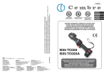
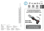
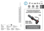
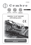
www.cembre.com
Cembre S.p.A.
Via Serenissima, 9
25135 Brescia (Italia)
Telefono: 030 36921
Telefax: 030 3365766
E-mail: [email protected]
www.cembre.it
Cembre España S.L.
Calle Verano, 6 y 8 - P.I. Las Monjas
28850 Torrejón de Ardoz - Madrid (España)
Teléfono: 91 4852580
Telefax: 91 4852581
E-mail: [email protected]
www.cembre.es
Cembre Ltd.
Dunton Park
Kingsbury Road, Curdworth - Sutton Coldfield
West Midlands B76 9EB (Great Britain)
Tel.: 01675 470440 - Fax: 01675 470220
E-mail: [email protected]
www.cembre.co.uk
Cembre AS
Fossnes Senter
N-3160 Stokke (Norway)
Phone: (47) 33361765
Telefax: (47) 33361766
E-mail: [email protected]
www.cembre.no
Cembre S.a.r.l.
22 Avenue Ferdinand de Lesseps
91420 Morangis (France)
Tél.: 01 60 49 11 90 - Fax: 01 60 49 29 10
B.P. 37 - 91421 Morangis Cédex
E-mail: [email protected]
www.cembre.fr
Cembre GmbH
Heidemannstraße 166
80939 München (Deutschland)
Telefon: 089/3580676
Telefax: 089/35806777
E-mail: [email protected]
www.cembre.de
cod. 6261104
This manual is the property of Cembre: any reproduction is forbidden without written permission.
12 M 025 U
Cembre Inc.
Raritan Center Business Park
181 Fieldcrest Avenue
Edison, New Jersey 08837 (USA)
Tel.: (732) 225-7415 - Fax: (732) 225-7414
E-mail: [email protected]
www.cembreinc.com
ENGLISH
Certified Quality
Management System
Certified Environmental
Management System
Certified Occupational
Health & Safety
Management System
BATTERY OPERATED
HYDRAULIC CRIMPING TOOL
B54-YD6
B54-YD6-8
B54-YK
OPERATION AND MAINTENANCE
MANUAL
WARNING
5
1
TG.0704
MOD. CB9630H 9,6V - 3,0Ah Ni-MH
6
3
1
2
Ni-MH
TG0702
4
5
3
2
Before using the tool, carefully read the instructions in this manual.
When operating the tool, keep hands away from the danger zone.
CDD6-8 jaw
6
3
See page 9.
5
2
1
Do not short circuit the batteries.
6
7
1
7
Always recycle the batteries.
Ni-MH
4
5
3
Do not discard batteries into domestic refuse or waste disposal.
2
CDK jaw
1
18
6
TABLE 3 (JAW)
Code N°
6000630
6600022
6520404
6520630
6180171
6760085
-
Item
6000630
6600022
6520404
6520630
6180171
6760085
-
6000631
6600022
6520404
6520630
6180171
6760085
6240007
CDD6 CDD6-8
1
2
3
4
5
6
7
Qty
DESCRIPTION
RUBBER COVER
DIE RETAINER PIN
SPRING
SPRING
M3 AUTOLOCK NUT
Ø 3x12 ELASTIC PIN
DIE RETAINER
2
2
2
1
2
2
2
with D3 groove to accept
all "W" style crimping dies
+ "BG" fixed groove
CDK
5
B54-YD6-8
-YD6-8
1
3
1
B54-YD6
6
with D3 groove to accept
all "W" style
tyle crimping dies
+ "O" fixed
ed groove
2
4
5
3
2
CDD6 jaw
B54-YK
4-YK
with groove
oove to accept all "O"
style Kearny
earny crimping dies.
Adapter to accept all "W"
mping dies available
style crimping
st
on request
6
17
2
BATTERY OPERATED HYDRAULIC CRIMPING TOOL
TABLE 2 (ITEM 10)
4
19
1. GENERAL CHARACTERISTICS
100
18
B54-YD6
TOOL TYPE:
B54-YD6-8
10
B54-YK
1
Application range:
suitable for installing electrical compression connectors
for conductors up to 150 mm2 (300 MCM)
Crimping force
kN (sh ton):
54 (6)
Rated operating pressure bar (psi):
Dimensions LxWxH
mm (inches):
340 (4,900)
kg (lbs):
2,9 (6.4)
Motor
Volt DC:
9.6
Battery type CB9630H
Volt / Ah:
9.6 / 3.0 Ni-MH
Battery charger supply
Volt / Hz:
120 / 50-60
7
AGIP ARNICA 22 or ESSO INVAROL EP22 or equivalent.
Safety:
the tool is equipped with a maximum pressure valve.
CDD 6
with D3 groove
to accept all "W"
style crimping
dies + "BG" fixed
groove
CDD 6-8
with D3 groove
to accept all "W"
style crimping
dies + "O" fixed
groove
210
8
Recommended oil:
(see table A page 9 for compatibility)
250
450 x 119 x 66 (17.7 x 4.7 x 2.6)
Weight with battery
Types of jaw supplied:
9
11
8
6
CDK
with groove to accept all "O"
style Kearny
crimping dies
20
11
15
220
220
57
17
21
Acoustic Noise (Directive 2006/42/EC, annexe 1, point 1.7.4.2 letter u)
– The weighted continuous acoustic pressure level equivalent
A at the work place LpA is equal to .............................................................................. 66,8 dB (A)
– The maximum value of the weighted acoustic displacement
pressure C at the work place LpCPeak is ......................................................................< 130 dB (C)
– The acoustic power level emitted by the machine
LWA is equal to ................................................................................................................ 75 dB (A)
500
400
Risks due to vibration (Directive 2006/42/EC, annexe 1, point 2.2.1.1)
Tests carried out in compliance with the indications contained in UNI ENV 25349 and UNI EN 28662
part 1st Standards, and under operating conditions much more severe than those normally found,
certify that the weighted root mean square in frequency of the acceleration the upper limbs
are exposed to for each biodynamic reference axis does not exceed 2.5 m/sec2.
15
300
7
3
16
9
14
16
*
TIGHTENING TORQUE
COUPLE DE SERRAGE
DREHMOMENT
PAR DE TORSION
COPPIA DI SERRAGGIO
8 Nm (5.9 lbf ft)
2. INSTRUCTIONS FOR USE
1
320
10
69
11
24
68
3
26
4
31
2
67
18
1
65
67
64
16
19
75
17
310
350
360
62
71
70
63
3
45
2
12
4
8
17
77
With the tool in the rest position (the ram fully retracted) proceed as follows:
– Select the appropriate groove or die set for the connector to be crimped.
– Insert the dies into the jaws of the tool (see § 2.8).
– Insert the conductor into the connector.
2.2) Die advancement (Ref. to Fig. 1)
Grip the tool firmly and comfortably.
– Position the connector in the groove
dies and ensure the correct location
of the crimp.
– Press operating button (3) to activate
the motor-pump group for the advancement of the ram. To halt the
advancement, release the operating
button and the motor will cut out.
Make sure the dies are exactly positioned on the desired crimp point
otherwise re-open dies following
instructions as per § 2.5 and reposition the connector.
13
6
30
*
66
65
11
2.1) Preparation
27
72
The tool is equipped with automatic return of the dies once the crimping operation is
completed.
The interchangeable crimping jaws have thermoplastic rubber covers on outside edges.
Residual battery capacity level is automatically displayed after every cycle.
The part reference “B54...” includes the following:
– Basic tool complete with battery
– Spare battery
– Battery charger complete with CBA96-144 adapter
– Canvas bag.
3
8
3
FIG. 1
9
5
16
15
600
15
4
2.3) Compression
TABLE 2 (ITEM 10 IN TABLE 1)
Insert the conductor in to the connector and press the operating button (3): the ram will
gradually move forward until the two dies touch. It is recommended to keep operating
until the maximum pressure valve is activated and a "click" is heard, after which the dies
will automatically re-open until the ram is fully retracted. It is always possible to interrupt
automatic retraction of the ram by a short push on the operating button (3).
2.4) Head rotation
For ease of operation the tool head can rotate through 180°, allowing the operator to work
in the most comfortable position.
Warning: do not attempt to rotate the head when the hydraulic circuit is pressurised.
2.5) Release of dies (Ref. to Fig. 1)
Press the pressure release button (8), the ram will retract and open the dies.
2.6) Battery status (Ref. to Fig. 2)
Inserting the battery into the tool or releasing
the operating button causes the residual battery capacity to be automatically displayed for
5 seconds on the indicator.
The number of LEDs illuminated indicates the
residual capacity.
6 LEDs illuminated: fully charged
FIG. 2
3 LEDs illuminated: 50 % capacity
1 LED illuminated: minimum charge
FIG. 3
2.7) Insertion/replacement of battery
To insert the battery, slide it into its seat until
it locks (Ref. to Fig. 3).
To replace an exhausted battery, press both
lateral red buttons simultaneously and slide
it forward.
5
Item
Code N°
6520200
6740120
3041735
6640205
6900052
6000602
6900054
6360022
6360125
6641020
6160081
6000697
6520240
6000318
6900021
6000849
6000608
6000596
6000588
6000601
6900602
6000620
6000621
6000632
6560200
6000622
6000623
6040564
6000624
6000633
6700051
6900013
6520030
6520601
6760420
6900180
14
300
300
300
300
300
300
300
300
300
300
300
300
300
300
300
300
300
300
300
300
300
600
600
600
600
600
600
600
600
600
600
600
600
600
600
600
DESCRIPTION
65
SPRING
66
7/32" BALL
67
TIE
68
D. 4 SCHNORR WASHER
69
M4x6 SCREW
70
LEVER SPRING
71
M4x6 SCREW
72
O-RING
75
O-RING
77
Ø 6 CU WASHER
310
BODY
320
RELEASE GROUP
320 1 SPRING
320 2 SPRING GUIDE
320 3 SCREW
320 4 D. 3 SCHNORR WASHER
320 65 SPRING SUPPORT
350
RESERVOIR CAP
360
COMPLETE LEVER SUPPORT
400
COMPLETE MEMBRANE
500
COMPLETE SUCTION SCREW
COMPLETE JAW SUPPORT
2
SUPPORT
3
ROLL
4
PIN ROLL
5
JAWS SUPPORT
6
SPRING
7
RAM GUIDE RING
8
PIN GRIP
9
JAW LOCKING PIN
12
Ø 10 CIRCLIP
13
M3x4 SCREW
14
RAM RETURN SPRING
15
SPRING
16
CYLINDRICAL PIN
17
M4x10 SCREW
Qty
1
1
2
1
1
1
1
1
1
1
1
1
1
1
1
1
1
1
1
1
1
1
1
2
2
1
1
1
1
1
1
1
1
1
1
1
2.8) Crimping die assembles
TABLE 2 (ITEM 10 IN TABLE 1)
Item
Code N°
6000625
6000233
6000357
6000358
6760004
6900008
6000849
6740020
6000363
6402009
6402006
6000328
6760012
6000315
6000231
6000229
6000227
6700080
6650136
6000232
6000595
6000619
6620122
6040240
6360300
6000560
6720072
6300027
6000561
6520232
6620378
6000563
6000575
6000565
6641027
6000567
6000603
6000570
6740100
6520160
6340590
11
100
100
100
100
100
100
100
100
100
100
100
100
100
100
100
100
100
100
100
100
300
300
300
300
300
300
300
300
300
300
300
300
300
300
300
300
300
300
300
300
DESCRIPTION
1
4
8
9
10
11
15
16
17
18
19
20
210
6
7
8
9
220
250
1
10
11
15
16
17
18
19
21
24
26
27
30
31
45
57
62
63
64
RUBBER GRIP
ACTUATING MECHANICAL GROUP
HOUSING
GEAR
Ø 2X8 CYLINDRICAL PIN
M3x6 SCREW
Ø 3 SCHNORR WASHER
1/4" BALL
GEAR
BEARING
WASHER
WASHER
CYLINDRICAL PIN
SPACER
COMPLETE DISC
DISC
BALLS SUPPORT
Ø 6 CIRCLIP
WASHER
COMPLETE CAM
COMPLETE MOTOR
COMPLETE HYDRAULIC GROUP
RAM
BACK-UP RING
O-RING
MEMBRANE RING
OIL RESERVOIR
VALVE PISTON
GRUB SCREW
VALVE SPRING
PUMPING RAM
VALVE ROD
SPRING SUPPORT
TEST PRESSURE CAP
WASHER
SETTING VALVE LOCKNUT
PRESSURE RELEASE LEVER
PUMPING RAM RETURN SPRING
5/32" BALL
SPRING
GRUB SCREW
Qty
1
1
1
1
3
2
2
2
3
1
1
1
2
3
1
1
1
1
1
1
1
1
1
1
1
1
1
1
1
1
1
1
1
1
1
1
1
1
1
1
1
2.8.1) Use of ”W” style crimping dies (B54-YD6, B54-YD6-8 tools)
– Press pins (2) and insert “W” dies into their seats (see Fig. 4A).
– To disassemble them simply press the pins and to slip them from the jaws.
2.8.2) Use of ”O” style Kearney crimping dies (B54-YK tool)
– Insert “O” dies into their seats, the two dies will be held by the retainers (7) (see Fig. 4B).
– To disassemble them simply slip them from the jaws.
Note: it is possible to use “W” style crimping dies with B54-YK by means of the AU55-B
adapter, available as an accessory.
IT IS RECOMMENDED TO USE THE TOOL ONLY WITH DIES INSERTED.
"W" style crimping dies
7
2
2
FIG. 4A
B54-YD6, B54-YD6-8 tools
13
"O" style crimping dies
6
7
2
2
FIG. 4B
B54-YK tool
2.9) Jaw replacement
Each tool is supplied with relevant jaws (see § 1).
Jaws can also be supplied separately, for replacement proceed as follows:
– Push and turn clockwise the locking pin (9) so
that the jaws are released.
– Slide the jaws out of the top of the tool and insert
the new ones (see Fig. 5).
– Fully insert the locking pin (9) into the tool and
lock it by turning clockwise until the red lines are
aligned.
16
3
9
red lines
8
5
FIG. 5
9
6
13
1
2.10) Using the battery charger
FIG. 6
Carefully follow the instructions in the
battery charger manual.
The tool is supplied with a battery
charger complete with adapter type
CBA96-144 required for 9,6V batteries (eg. CB9630H) (see Fig. 6).
With the adaptor removed, the same
charger may be used with the 14,4V
batteries (eg. CB1430H) common to
the other Cembre battery operated
tools.
7
11
XXXXXX
4
45
Serial number of tool
Adapter CBA96-144
7
12
2
3. WARNING
TABLE 1
Before starting work on electrical equipment, please ensure that either there are no live parts in
the immediate working area or that precautions are taken for working near live parts in
accordance with EN50110-1.
See TABLE 2
10
DO NOT USE THIS TOOL ON OR NEAR ENERGISED CONDUCTORS WITHOUT PROPER
PERSONAL PROTECTIVE EQUIPMENT. FAILURE TO OBSERVE THIS WARNING COULD
RESULT IN SEVERE INJURY OR DEATH.
THE TOOL IS UNSUITABLE FOR CONTINUOUS USE AND SHOULD BE ALLOWED TO
COOL DOWN FOLLOWING UNINTERRUPTED, SUCCESSIVE CRIMPING OPERATIONS;
FOR INSTANCE, HAVING EXHAUSTED A FULLY CHARGED BATTERY IN ONE SESSION,
DELAY BATTERY REPLACEMENT FOR A FEW MINUTES.
OBSERVE RECOMMENDED REST PERIODS ALSO WHEN USING AN EXTERNAL POWER
SUPPLY.
PROTECT
THE TOOL FROM RAIN AND MOISTURE. WATER WILL DAMAGE THE TOOL
AND BATTERY. ELECTRO-HYDRAULIC TOOLS SHOULD NOT BE OPERATED IN POURING
RAIN OR UNDER WATER.
3.1) General information on how to use batteries
In order to maximise battery life, please follow these rules:
– Use the battery until the automatic residual energy display still has 1-2 red LEDs showing:
this means the battery is almost completely discharged and no loss in the life of the
battery has been caused.
– Be particularly careful when charging a new battery the first 2-3 times in order to be
certain of maximising the available energy level.
– Allow the battery to cool down to ambient temperature prior to recharging.
– Rest the battery charger for at least 15 minutes between charges.
17
4. MAINTENANCE
The tool is robust, completely sealed, and requires very little daily maintenance.
Compliance with the following points, should help to maintain the optimum performance
of the tool:
12
4.1) Thorough cleaning
Dust, sand and dirt are a danger for any hydraulic device.
Every day, after use, the tool must be wiped with a clean cloth taking care to remove any
residue, especially close to moveable parts.
4.2) Storage
When not in use, the tool and accesories should be stored and transported in the relevant
canvas bag to prevent damage.
11
8
TABLE A
5. RETURN TO Cembre FOR OVERHAUL
INTERCHANGEABLE CRIMPING JAWS
JAW TYPE
GROOVES
CDD6
“D3” TO ACCEPT ALL “W” STYLE
CRIMPING DIES + “BG” FIXED
GROOVE
CDD6-8
“D3” TO ACCEPT ALL “W” STYLE
CRIMPING DIES + “O” FIXED
GROOVE
GROOVE TO ACCEPT ALL “O”
STYLE KEARNEY CRIMPING DIES;
CDK
AU55-B ADAPTER TO ACCEPT
ALL “W” STYLE CRIMPING DIES
AVAILABLE AS AN ACCESSORY
CRIMPING DIE COMPATIBILITY
In the case of a breakdown contact our Area Agent who will advise you on the problem
and give you the necessary instructions on how to dispatch the tool to our nearest service
Centre; if possible, attach a copy of the Test Certificate supplied by Cembre together
with the tool or, if no other references are available, indicate the approximate purchase
date and the tool serial number.
FCI Burndy
W, X Series
Greenlee
KD6 Series
Ilsco
ND Series
Huskie
HT-58 Series
Panduit
CD-2001 series
The guarantee is void if parts used are not Cembre original spares.
FCI Burndy
W, X Series
Greenlee
KD6 Series
Ilsco
ND Series
Huskie
HT-58 Series
When ordering spare parts always specify the following:
- code number of item
- name of item
- type of tool
- serial number of tool
Panduit
CD-2001 Series
Kearney
O Series
Blackburn
6 tons
SPARE PARTS LIST
TABLE 1
Item
Code N°
- Following information applies in member states of the European Union:
USER INFORMATION in accordance with “Directives 2002/95/EC and
2002/96/EC regarding the reduction of hazardous substances in electrical and electronic equipment, including the disposal of waste”.
The 'Not in the bin' symbol above when shown on equipment or packaging means that the equipment must, at the end of its life, be disposed of
separately from other waste.
The separate waste collection of such equipment is organised and managed by the manufacturer.
Users wishing to dispose of such equipment must contact the manufacturer and follow the prescribed guidelines for its separate collection.
Appropriate waste separation, collection, environmentally compatible
treatment and disposal is intended to reduce harmful environmental effects and promote the reuse and recycling of materials contained in the
equipment.
Unlawful disposal of such equipment will be subject to the application of
administrative sanctions provided by current legislation.
9
DESCRIPTION
Qty
6000577
2598504
6000579
6000584
6000591
6000593
6000580
6000581
6000582
6000618
6000586
6900650
6000589
6232518
6232500
1
2
3
4
5
6
7
8
9
10
11
12
13
16
17
RIGHT + LEFT SHELL
CB9630H BATTERY
OPERATING BUTTON
PROTECTION
ROD
SPRING
CONTACT SUPPORT
PRESSURE RELEASE BUTTON
BUTTON REINFORCEMENT
MECHANICAL GROUP (see table 2)
COMPLETE ELECTRICAL CIRCUIT
3,5X16 SCREW
WRIST STRAP
TG.0729 LABEL
TG.0704 LABEL
1
1
1
1
1
1
1
1
1
1
1
6
1
1
1
6232654
45
TG.0891 LABEL
1
10