1
M
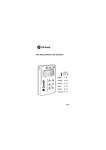
M5097
Multimeter
User Guide
Guide de l’utilisateur
Bedienungsanleitung
SAFETY WARNINGS
✱ Measurements beyond the maximum selected range must not be attempted.
✱ Extreme care must be taken when measuring above 50 V, especially on live bus-bars.
✱ To measure voltage, the instrument must not be switched to a current or resistance range, or to the diode check position.
✱ Circuits must be de-energised and isolated before carrying out resistance tests.
✱ The rotary selector switch must only be turned after removing test connections.
✱ All external voltages must be disconnected from the instrument before removing the battery.
✱ Test leads, prods and crocodile clips must be in good order; clean, and with no broken or cracked insulation.
✱ UK Safety Authorities recommend the use of fused test leads when measuring voltage on high energy systems.
✱ Replacement fuses must be of the correct type and rating.
✱ The instrument must not be used if any part of it is damaged.
✱ Warnings and precautions must be read and understood before an instrument is used. They must be observed during
NOTE
THE INSTRUMENT MUST ONLY BE USED BY SUITABLY TRAINED AND COMPETENT PERSONS.
2
User Guide - Contents
Guide de Utilisateur - p. 13
Safety Warnings
2
Display Features
4
Gebrauchsanleitung - s. 24
Symbols used on instrument
Caution: risk of electric shock
Operation
Resistance measurement
Continuity beeper
Diode test
Votage measurement
Current measurement
Battery replacement
Fuse replacement
5
5
5
5
5
6
6
Specification
7
Accessories
11
Repair and Warranty
12
Caution: refer to acompanying notes
Equipment protected throughout by Double
Insulation (Class II)
Equipment complies with relevant EU Directives
Note
Users of this equipment and/or their employers are reminded that
Health and Safety Legislation require them to carry out valid risk
assessments of all electrical work so as to identify potential sources of
electrical danger and risk of electrical injury such as from inadvertent
short circuits. Where the assessments show that the risk is significant
then the use of fused test leads constructed in accordance with the
HSE guidance note GS38 ‘Electrical Test Equipment for use by
Electricians’ should be used.
3
Display Features
Hold
Manual
ranging
On
Beeper
Diode
Low
Battery
Press to select ‘Manual Ranging‘.
is displayed.
RANGE
DELAY
HOLD
RESET
H
H
Press to select ‘Hold‘ after a 6 secs
delay period.
Beep sounds and
Press to toggle between ranges.
Push and hold for 2 secs to reset
to ‘AutoRanging‘.
4
HOLD
is displayed.
H
Press to select ‘Hold‘.
Beep sounds and
HOLD
is displayed.
Press ‘HOLD‘ switch to cancel.
Press ‘HOLD‘ switch to cancel.
Beep sounds when cancelling.
Beep sounds when cancelling.
Press to toggle between
Current
options. The selected option icon is
displayed.
Press to toggle between the
and
features.
The selected option icon is displayed.
Operation
Refer to Safety Warnings before using the instrument
4.
Resistance measurement
1.
Set the selector switch to the desired Ω range position.
2.
Connect the Red test lead to the +VΩ
terminal socket and the
Black test lead to the
terminal socket.
3.
Ensure that the device under test contains no voltage. Connect the
test prods across the device.
4.
5.
symbol together
If required, press the HOLD button. The HOLD
with the value are held on the display. To cancel, press HOLD again.
Read the measurement directly from the display which will include
the test lead resistance. Test lead resistance can be subtracted from
the displayed result to give more accurate measurement of the
device under test.
Continuity Beeper
1.
Set the selector switch to
2.
3.
4.
5.
5.
to the
terminal socket and the junction cathode.
For a reverse bias test, connect the connect the Red test lead to the
+VΩ
terminal terminal socket and the junction cathode. Connect
terminal socket and the junction anode.
the Black test lead to the
Read the measurement directly from the display. A good diode will
show a forward voltage drop of between 400 mV and 900 mV. If the
diode is short circuit the display will show
or if open circuit
.
Voltage measurement
1.
Set the selector switch to V or V
position.
terminal socket and the
2.
Connect the Red test lead to the +VΩ
Black test lead to the
terminal socket.
3.
Connect the test prods across of the circuit to be measured.
4.
5.
If required, press the HOLD button. The HOLD
symbol together
with the value are held on the display. To cancel, press HOLD again.
Read the measurement directly from the display.
.
Toggle the
button and ensure the
symbol is displayed.
Connect the Red test lead to the +VΩ
terminal socket and the
Black test lead to the
terminal socket.
Ensure that the device under test contains no voltage. Connect the
test prods across the device.
The beeper sounds continuously when the resistance < 50 Ω.
Current measurement
Switch off the circuit when making or breaking connections
1.
2.
Diode Test
1.
Set the selector switch to
2.
3.
Toggle the
button and ensure the
symbol is displayed.
For a forward bias test, connect the Red test lead to the +VΩ
terminal socket and the junction anode. Connect the Black test lead
.
3.
4.
Set the selector switch to A
; mA
or µA
position as
appropriate.
Connect the Red test lead to the µA / mA terminal socket, or the A
terminal socket for the 10 Amp range. Connect the Black test lead to the
terminal socket. Note:- The instrument will beep if test leads are
connected to a current input terminal but the rotary switch is not on the
corresponding position.
Toggle the
button and ensure the AC or DC symbol is
displayed, as required.
Connect the test prods in series in the circuit to be measured.
5
Operation
5.
6.
If required, press the HOLD button. The HOLD
symbol together
with the value are held on the display. To cancel, press HOLD again.
Read the measurement directly from the display.
6.
7.
Battery Replacement
Select OFF and disconnect the test leads from the terminals
1.
2
3.
4.
5.
6.
7.
8.
Remove the holster and place the instrument face downwards.
Remove the 3 screws securing the back of the case.
Lifting the rear half of the case, gently separate the 2 halves of the
case
Lift out the battery holder. Note the polarity of, and remove the cells
Observing correct polarity, replace the cells with new 1,5 V IEC LR03
type.
Replace the battery holder in the case.
Replace the rear half of the case, ensuring that the connector wires
will not be pinched when the case is re-assembled, and that the
sealing gasket is properly seated.
Replace the 3 securing screws.
Fuse Replacement
Select OFF and disconnect the test leads from the terminals
1.
2
3.
4.
5.
6
Remove the holster and place the instrument face downwards.
Remove the 3 screws securing the back of the case.
Lifting the rear half of the case, gently separate the 2 halves of the
case
Gently ease the PCB assembly out of the front half of the case, and
turn it so that the display is uppermost. Do not remove any screws
from the PCB itself as these hold the PCB assembly together.
The fuse is clipped to the bottom of the assembly, adjacent to the
terminal sockets.
8.
9.
Carefully prise out the old fuse and replace it with a fuse of the
correct type and rating. See Specification.
Ensure that both halves of the rotary switch are aligned, and carefully
replace the PCB assembly in the front half of the case. The switch
will
be aligned if it has not been moved.
Replace the rear half of the case, ensuring that the connector wires
will not be pinched when the case is re-assembled, and that the
sealing gasket is properly seated.
Replace and tighten the 3 securing screws.
Specification
AC Volts
Range
Resolution
3V
30V
300 V
750 V
1 mV
10 mV
100 mV
1V
Frequency Response:
Input impedance:
40 Hz - 300 Hz for 3 V range.
10 MΩ // l <100 pF.
*AC Conversion Type:
Average sensing RMS. indication.
*** Crest Factor:
1.4 to 2.0, add 0,5% to accuracy.
2.0 to 2.5, add 2% to accuracy.
2.5 to 3.0, add 4% to accuracy.
Accuracy
± (1,3%
± (1,3%
± (1,3%
± (1,3%
rdg
rdg
rdg
rdg
+
+
+
+
5
5
5
5
Overvoltage protection
digits)*
digits)
digits)
digits)
1100
1100
1100
1100
V
V
V
V
p-p
p-p
p-p
p-p
DC Volts
Range
Resolution
300 mV
30 V
300 V
1000 V
100µV
1 mV
100 mV
1V
Input impedance:
Accuracy
± (0,5%
± (0,5%
± (0,5%
± (0,5%
+
+
+
+
2
2
2
2
Overvoltage protection
digits)
digits)
digits)
digits)
1100
1100
1100
1100
V
V
V
V
d.c.
d.c.
d.c.
d.c.
10 MΩ
AC Current
Range
300 µA
3 mA
30 mA
300 mA
10 A continuous
20 A for 30 sec.
Resolution
0.1 A
1 µA
10 µA
0.1 mA
10 mA
10 mA
Accuracy
± (1,5%
± (1,5%
± (1,5%
± (2,0%
± (2,5%
± (2,5%
rdg
rdg
rdg
rdg
rdg
rdg
+
+
+
+
+
+
3
3
3
3
5
5
Voltage Burden
digits)
digits)
digits)
digits)
digits)
digits)
200 mV max.
2 V max.
200 mV max.
2 V max.
2 V max.
2 V max.
7
Specification
Frequency Response:
Overload protection:
40 Hz - 500 Hz
1 A (500 V) fast blow fuse for µA / mA input. 10 A (500 V) for A input
DC Current
Range
Resolution
300 µA
3 mA
30 mA
300 mA
10 A continuous
20 A for 30 sec.
Accuracy
0.1 A
1 µA
10 µA
10 µA
10 mA
10 mA
Overload protection:
± (1,0%
± (1,2%
± (1,0%
± (1,2%
± (2,0%
± (2,0%
rdg
rdg
rdg
rdg
rdg
rdg
Voltage Burden
+ 2 digits)
+2 digits)
+ 2 digits)
+2 digits)
+ 3 digits)
+ 3 digits)
200 mV max.
2 V max.
200 mV max.
2 V max.
2 V max.
2 V max.
1 A (500 V) fast blow fuse for µA / mA input. 10 A (500 V) for A input
Resistance
Range
Resolution
300 Ω
3 kΩ
30 kΩ
300 kΩ
3 MΩ
30 MΩ
0,1 Ω
1Ω
10 Ω
100 Ω
1 kΩ
10 kΩ
Open Circuit Voltage:
1,3 V approx.
Overload protection:
600 V DC / AC RMS max.
Accuracy
± (1,0%
± (0,8%
± (0,8%
± (0,8%
± (1,2%
± (2,5%
rdg
rdg
rdg
rdg
rdg
rdg
+
+
+
+
+
+
4
2
2
2
3
5
Overvoltage protection
digits)
digits)
digits)
digits)
digits)
digits)
600
600
600
600
600
600
V
V
V
V
V
V
d.c.
d.c.
d.c.
d.c.
d.c.
d.c.
or
or
or
or
or
or
600
600
600
600
600
600
V
V
V
V
V
V
rms
rms
rms
rms
rms
rms
Diode Check and Continuity
Range
Resolution
1 mV
8
Accuracy
±(1,5% rdg+ 5 digits)
Max. Test current
1,5 mA (for 0.4 V - 0.8 V)
Max. Open Circuit voltage
3,3 V
Temperature Range:
Operating:
Storage:
0˚C to + 50˚C
- 20˚C to + 60˚C (Battery removed).
Temperature Coefficient:
0,15 x specified accuracy/˚C. < 18˚C or > 28˚C.
Safety:
The instrument meets the requirements for double insulation to IEC 1010-1 (1995) EN 61010-1 (1995) to:
Terminal V/R:
Installation Category III***, 300 V phase to earth, and 500 V phase to phase.
Installation Category II**, 600 V phase to earth, 750 V a.c. and 1 kV d.c. phase to phase.
Installation Category I*, 750 V a.c. and 1 kV d.c.
Terminal mA/µA:
Installation Category III***, 500 Volts d.c
Installation Category II**, 250 Volts d.c.
Terminal A:
Installation Category III***, 500 Volts a.c.
Installation Category II**, 250 Volts d.c.
*** Relates to transient overvoltage likely to be found in fixed installation wiring.
** Relates to transient overvoltage likely to be found in portable equipment and appliances.
* Relates to transient overvoltage likely to be found in special equipment or parts of equipment, telecommunication, electronic etc.
Humidity Range: Operating:
Storage:
0 to 80% RH at 0˚C to + 50˚C.
0 to 80% RH at -20˚C to + 60˚C (Battery removed).
AC Conversion Type:
Average sensing, RMS. indication
Display:
Sample Rate:
3200 count LCD with 65 segment analogue bar graph, auto indication and Over-range indication
2 per second for digital. 12 per second for Analogue Bargraph.
Battery Type:
2 x 1,5 V Alkaline cells IEC LR03 type
9
Specification
Battery Life:
Alkaline - Typically 1000 hours of use.
Auto power Off:
After 10 minutes of inactivity by the instrument. To restore operation after Auto-shut Off, press RESET button.
Low Battery indication:
- +
displayed when battery voltage drops below operating value.
Fuses:
1 A, 500 V (F) HBC ceramic type
10A, (F) HBC ceramic type
EMC:
Meets EN 50081-1 and EN 50082-1 (1992)
Dimensions:
84 mm x 175 mm x 31 mm, without holster
95 mm x 192 mm x 50 mm, with holster
Weight:
345g (3⁄4lb. approx)
Cleaning:
Wipe disconnected instrument with a clean cloth damped with soapy water or Isopropyl Alcohol (IPA)
10
Accessories
Supplied
User Guide
Part Number
6172-246
Holster
8101-059
Test leads set with prods
6220-437
Optional
Fused Test lead set FPK8
400 A Current Transducer
111-218
DCM2031
11
Repair and Warranty
The instrument circuit contains static sensitive devices, and care must be
taken in handling the printed circuit board. If the protection of an instrument
has been impaired it should not be used, and be sent for repair by suitably
trained and qualified personnel. The protection is likely to be impaired if, for
example, the instrument shows visible damage, fails to perform the intended
measurements, has been subjected to prolonged storage under
unfavourable conditions, or has been exposed to severe transport stresses.
New Instruments are Guaranteed for 1 Year from the Date of
Purchase by the User.
Note:
Any unauthorized prior repair or adjustment will automatically
invalidate the Warranty.
Instrument Repair and Spare Parts
For service requirements for MEGGER® Instruments contact:
AVO INTERNATIONAL
or
Archcliffe Road
Dover
Kent, CT17 9EN.
England.
U.K.
Tel: +44 (0) 1304 502243
Fax: +44 (0) 1304 207342
AVO INTERNATIONAL
Valley Forge
Corporate Center
2621 Van Buren Avenue
Norristown, PA 19403
U.S.A.
Tel: +1 (610) 676-8579
Fax: +1 (610) 643-8625
or an approved repair company.
Approved Repair Companies
A number of independent instrument repair companies have been approved
for repair work on most MEGGER® instruments, using genuine
12
MEGGER® spare parts. Consult the Appointed Distributor / Agent
regarding spare parts, repair facilities and advice on the best course of
action to take
Returning an Instrument for Repair
If returning an instrument to the manufacturer for repair, it should be sent
freight pre -paid to the appropriate address. A copy of the Invoice and of the
packing note should be sent simultaneously by airmail to expedite clearance
through Customs. A repair estimate showing freight return and other charges
will be submitted to the sender, if required, before work on the instrument
commences.
AVERTISSEMENTS RELATIFS A LA SECURITE
✱ Ne jamais essayer de prendre des mesures au-delà du maximum de la gamme sélectionnée.
✱ Des soins particuliers doivent être pris pour les mesures de plus de 50 V, en particulier sur les barres omnibus sous tension.
✱ Pour mesurer les tensions, l’instrument ne doit pas être réglé sur une gamme de courant ou de résistance, ni sur la position
d’essai de diode.
✱ Les circuits doivent être désexcités et isolés avant d’effectuer des essais de résistance.
✱ Le commutateur rotatif ne doit être tourné qu’après avoir débranché les câbles d’essai.
✱ Toutes les tensions externes doivent être déconnectée de l’instrument avant de retirer la pile.
✱ Les câbles d’essai, les pointes et les pinces crocodiles doivent être en bon état, propres et leur isolement ne doit être ni
fissuré ni cassé.
✱ Les Services de sécurité britanniques recommandent l’utilisation de câbles d’essai équipés de fusibles pour la mesure de la
tension des systèmes à haute énergie.
✱· Les fusibles de remplacement doivent être du type, de la taille et de la puissance corrects.
✱ L’instrument ne doit pas être utilisé si l’une quelconque de ces parties est endommagée.
✱ Les avertissements relatifs à la sécurité doivent être lus et compris avant d’utiliser l’instrument. Ils doivent être observés
endant
NOTE
LES INSTRUMENTS NE DOIVENT ETRE UTILISES QUE PAR DES PERSONNES COMPETENTES AYANT RECU LA FORMATION APPROPRIEE.
13
Guide de Utilisateur - Contenu
User Guide - p.2
Avertissements relatifs à sécurité
13
Caracteristiques de l’affichage
15
Gebrauchsanleitung - s.24
Symboles utilisés sur l’ instrument
Attention: risque d’electrocution
Fonctionnement
Mesure de résistance
Avertisseur de continuité
Essai de diode
Mesure de tension
Mesure de courant
Remplacement des piles
Remplacement du fusible
16
16
16
16
16
17
17
Specification
18
Accessoires
22
Reparations et Garantie
23
Attention: consulter les notes accompagnatrices
Equipement totalement protegé par un double
isolement (Categorié II)
L’equipement est conforme aux Directives EU
applicables.
Note
Il est rappelé aux utilisateurs de cet instrument et/ou à leurs
employeurs que la législation relative à la santé et à la sécurité stipule
qu’ils doivent évaluer les risques de tous les travaux électriques de
manière à identifier les sources possibles de danger électrique et les
risques de blessure tels que ceux des courts-circuits involontaires.
Lorsque ces évaluations indiquent des risques importants, des câbles
d’essai équipés de fusibles et réalisés conformément au guide du HSE
GS28 “Equipements d’essai électrique pour électriciens”, doivent être
utilisés.
14
Caracteristiqes de l’affichage
Maintien
Plage
manuelle
activée
Avertisseur
sonore
Diode
Pile
déchargée
RANGE
DELAY
HOLD
RESET
H
H
Appuyer pour sélectionner ‘Plage
manuelle’.
Appuyer pour sélectionner ‘Maintien’
après un délai de 6 secondes.
est affiché.
Appuyer pour faire défiler les
gammes
L’avertisseur retentit et
affiché.
Appuyer pendant 2 secondes pour
revenir à ‘Plage automatique’‘
HOLD
H
Appuyer pour sélectionner ‘Maintien’.
L’avertisseur retentit et
affiché.
HOLD
est
est
Appuyer sur la touche ‘HOLD’ pour
annuler. L’avertisseur retentit lors de
l’annulation.
Appuyer sur la touche ‘HOLD’ pour
annuler
Appuyer pour faire défiler les options
Courant.
L’icône de l’option choisie est affichée.
Appuyer pour passer entre les fonctions
et
L’icône de l’option choisie est
affichée.
L’avertisseur retentit lors de
l’annulation.
15
Fonctionnement
Consultez les avertissements relatifs à la sécurité
avant d’utiliser l’instrument
Mesure de résistance
1.
Placer le sélecteur à la position de gamme Ω requise.
et le câble
2.
Connecter le câble d’essai Rouge à la borne +VΩ
d’essai Noir à la borne .
3.
Vérifier que le dispositif à tester ne contient aucune tension.
Appliquer les pointes d’essai sur le dispositif.
4.
5.
Si nécessaire, appuyer sur le bouton HOLD. Le symbole HOLD et la
valeur de la résistance reste affichés sur l’écran. Appuyer de
nouveau sur HOLD pour les annuler.
Lire la mesure directement sur l’affichage, qui comprendra la
résistance des câbles d’essai. La résistance des câbles d’essai peut
être déduite du résultat affiché pour donner une mesure plus précise
du dispositif testé.
Avertisseur de continuité
1.
Placer le sélecteur à la position
2.
3.
4.
5.
.
16
4.
5.
5.
Si nécessaire, appuyer sur le bouton HOLD. Le symbole HOLD et la
valeur de la tension reste affichés sur l’écran. Appuyer de nouveau
sur HOLD pour les annuler.
Lire la mesure directement sur l’affichage.
Mesure de courant
Couper le circuit pendant la connexion et la déconnexion
1.
2.
est
affiché.
Pour un essai de polarisation directe, connecter le câble d’essai
Rouge à la borne +VΩ
et à l’anode de jonction. Connecter le
et à la cathode de jonction.
câble d’essai Noir à la borne
Pour un essai de polarisation inverse, connecter le câble d’essai
Rouge à la borne +VΩ
et à la cathode de jonction. Connecter le
câble d’essai Noir à la borne ¡ et à l’anode de jonction.
Lire le résultat directement sur l’affichage. Une bonne diode aura une
chute de tension directe comprise entre 400 et 900 mV. Si la diode
est en court-circuit, l’affichage indiquera
; si elle est en circuit
ouvert, l’affichage
.
Mesure de tension
1.
Placer le sélecteur à la position V
ou à la position V .
2.
Connecter le câble d’essai Rouge à la borne +VΩ
et le câble
d’essai Noir à la borne .
3.
Appliquer les pointes d’essai sur le circuit à mesurer.
4.
Appuyer sur le bouton
et vérifier que le symbole
est
affiché.
Connecter le câble d’essai Rouge à la borne +VΩ
et le câble
d’essai Noir à la borne .
Vérifier que le dispositif à tester ne contient aucune tension.
Appliquer les pointes d’essai sur le dispositif.
L’avertisseur émet une tonalité continue lorsque la résistance est <
50Ω.
Essai de diode
1.
Placer le sélecteur à la position
.
2.
Appuyer sur le bouton
et vérifier que le symbole
3.
Placer le sélecteur à la position A
ou à la position mA
selon
le cas.
Connecter le câble d’essai Rouge à la borne mA/mA, ou à la borne
A pour la gamme de 10A. Connecter le câble d’essai Noir à la borne
. Note: L’instrument émettra un bip sonore si les câbles d’essai
sont connectés à une borne d’entrée de courant qui ne correspond
pas à la position du sélecteur.
3.
4.
5.
6.
3.
4.
Appuyer sur le bouton
et vérifier que le symbole AC ou DC
est affiché selon le cas.
Connecter les pointes d’essai en série avec le circuit à mesurer.
Si nécessaire, appuyer sur le bouton HOLD. Le symbole HOLD et la
valeur du courant reste affichés sur l’écran. Appuyer de nouveau sur
HOLD pour les annuler.
Lire la mesure directement sur l’affichage.
Remplacement des piles
5.
6.
7.
Sélectionner OFF et déconnecter les câbles d’essai des bornes
1.
2.
3.
4.
5.
6.
7.
8.
Retirer l’étui et placer l’instrument face vers le bas.
Déposer les trois vis de fixation de l’arrière du boîtier.
Soulever la moitié arrière du boîtier, séparer soigneusement les deux
moitiés du boîtier.
Soulever le porte-piles, noter la polarité et déposer les piles
Remplacer les piles par des piles neuves de 1,5V du type IEC LR03.
Remonter le porte-piles dans le boîtier.
Remonter la moitié arrière du boîtier en prenant soin de ne pas
pincer les fils du connecteur, et en vérifiant que le joint est bien en
place.
Remonter les trois vis de fixation.
8.
9.
Soulever la moitié arrière du boîtier, séparer soigneusement les deux
moitiés du boîtier.
Retirer soigneusement la carte de circuits imprimé en la tirant par la
moitié avant du boîtier et en la tournant de manière à amener
l’affichage vers le haut. Ne déposer aucune vis de la carte ellemême, car elles assurent la fixation de l’ensemble de carte de
circuits imprimés.
Le fusible est agrafé sur le dessous de l’ensemble, à côté des bornes
femelles.
Déposer soigneusement le vieux fusible, et le remplacer par un
fusible du type et de la puissance nominale corrects. Voir
Spécifications.
Vérifier que les deux moitiés du commutateur rotatif sont bien
alignées, et remonter soigneusement la carte de circuits imprimés
dans la moitié avant du boîtier. Le commutateur sera aligné s’il n’a
pas été déplacé.
Remonter la moitié arrière du boîtier, en prenant soin de ne pas
pincer les fils du connecteur, et en vérifiant que le joint est bien en
place.
Remonter et serrer les trois vis de fixation.
Remplacement du fusible
Sélectionner OFF et déconnecter les câbles d’essai des bornes
1.
2.
Retirer l’étui et placer l’instrument face vers le bas.
Déposer les trois vis de fixation de l’arrière du boîtier.
17
Specifications
Tension CA
Gamme
3V
30V
300 V
750 V
*Reponse en fréquence:
Impedance d’entrée:
Type de conversion CA:
*** Facteur de créte:
Résolution
1 mV
10 mV
100 mV
1V
40 Hz - 300 Hz for 3 V range.
10 MΩ // l <100 pF.
Précision
± (1,3%
± (1,3%
± (1,3%
± (1,3%
lecture
lecture
lecture
lecture
Protection de surtension
+
+
+
+
5
5
5
5
chiffres)*
chiffres)
chiffres)
chiffres)
1100
1100
1100
1100
V
V
V
V
créte
créte
créte
créte
à
à
à
à
créte
créte
créte
créte
Détection moyenne indication efficace
1,4 à 2,0 ajouter 0,5% à la précision
2,0 à 2,5 ajouter 2% à la précision
2,5 à 3,0 ajouter 4% à la précision
Tension CC
Gamme
Résolution
300 mV
30 V
300 V
1000 V
100µV
1 mV
100 mV
1V
Impédance d’entrée:
Précision
±(0,5%
±(0,5%
±(0,5%
±(0,5%
± 2 chiffres)
± 2 chiffres)
+ 2 chiffres)
+ 2 chiffres)
Protection de surtension
1100
1100
1100
1100
V
V
V
V
c.c.
c.c.
c.c.
c.c.
10 MΩ
Courant CA
Gamme
300 µA
3 mA
30 mA
300 mA
10 A continu
20 A pour 30 s
18
Résolution
0.1 A
1 µA
10 µA
0.1 mA
10 mA
10 mA
Précision
± (1,5% lecture + 3 chiffres)
± 1,5% lecture + 3 chiffres)
± (1,5% lecture + 3 chiffres)
± (2,0% lecture + 3 chiffres)
± (2,5% lecture + 5 chiffres)
± (2,5% lecture + 5 chiffres)
Tension de charge
200 mV maxi.
2 V maxi.
200 mV maxi.
2 V maxi.
2 V maxi.
2 V maxi.
Réponse en fréquence:
40 Hz - 500 Hz
Protection de surcharge:
Fusible 1 A(500 V) à fusion rapide pour entrée µA / mA.
10 A (500 V) pour entrée A
Courant CC
Gamme
Résolution
300 µA
3 mA
30 mA
300 mA
10 A continuous
20 A for 30 sec.
Précision
0.1 A
1 µA
10 µA
10 µA
10 mA
10 mA
Protection de surcharge:
± (1,0%
± (1,2%
± (1,0%
± (1,2%
± (2,0%
± (2,0%
lecture
lecture
lecture
lecture
lecture
lecture
Tension de charge
+ 2 chiffres)
+2 chiffres)
+ 2 chiffres)
+ 2 chiffres)
+ 3 chiffres)
+ 3 chiffres)
200 mV maxi.
2 V maxi.
200 mV maxi.
2 V maxi.
2 V maxi.
2 V maxi.
Fusible 1A (500 V) à fusion rapide pour entrée µA/mA. Fusible 10 A (500 V) pour entrée A
Résistance
Gamme
Résolution
300 Ω
3 kΩ
30 kΩ
300 kΩ
3 MΩ
30 MΩ
0,1 Ω
1Ω
10 Ω
100 Ω
1 kΩ
10 kΩ
Précision
± (1,0%
± (0,8%
± (0,8%
± (0,8%
± (1,2%
± (2,5%
Tension de circuit ouvert:
1,3 V approx.
Protection de surcharge:
600 V CC / CA efficace maximum.
Gamme
Résolution
lecture
lecture
lecture
lecture
lecture
lecture
+
+
+
+
+
+
4
2
2
2
3
5
chiffres)
chiffres)
chiffres)
chiffres)
chiffres)
chiffres)
Verification de diode et continuité
Courant d’essai
Précision
maximum
Protection de surtension
600
600
600
600
600
600
V
V
V
V
V
V
c.c.
c.c.
c.c.
c.c.
c.c.
c.c.
ou
ou
ou
ou
ou
ou
600
600
600
600
600
600
V
V
V
V
V
V
eff.
eff.
eff.
eff.
eff.
eff.
Tension de circuit
ouvert maximum
19
Specifications
1 mV
Plage de température:
Exploitation:
Stockage:
±(1,5% lecture + 5 chiffres)
1,5 mA (Pour 0.4 V - 0.8 V)
3,3 V
0˚C à + 50˚C
- 20˚C à + 60˚C (Pile déposée).
Safety: L’ instrument répond aux exigences d’isolement double des normes IEC 1010-1 (1995) EN 61010-1 (1995) comme suite:
***
**
*
Borne V/R:
Catégorie d’Installation III***, 300V phase à masse, et 500 V entre phase.
Catégorie d’Installation II**, 600 V phase à masse, et 750 V c.a. et 1 kV c.c. entre phase.
Catégorie d’Installation I*, 750 V c.a.. et 1 kV c.c.
Borne mA/µA:
Catégorie d’Installation III***, 500 V c.a.
Catégorie d’Installation II**, 250 V c.c.
Borne A:
Catégorie d’Installation III***, 500 V c.a.
Catégorie d’Installation II**, 250 V c.c.
Concerne une surtension transitoire pouvant éventuellement être rencontrée dans les installations fixes.
Concerne une surtension transitoire pouvant éventuellement être rencontrée dans les équipements et appareils portables.
Concerne une surtension transitoire pouvant éventuellement être rencontrée dans les équipements spéciaux ou des parties d’équipements, dans
les télécommunications, l’électronique, etc.
Type de conversion CA: Détection moyenne, indication efficace
Affichage:
LCD 3200 comptage avec diagrammes à barres analogue à 65 segments, indication auto et indication de dépassement de
gamme
Echantillage:
2 par seconde pour numerique. 12 par seconde pour diagrammes à barres analogue.
Coefficient de T˚:
Plage d’humidité:
Exploitation:
Stockage:
0,15 x précision spécifiée /˚C. < 18˚C ou > 28˚C.
20
0 à 80% RH at 0˚C et + 50˚C.
0 à 80% RH at -20˚C et + 60˚C (pile déposée).
Type de pile:
2 piles alcalines 1,5 V type IEC LR03
Durée des piles
Alcaline - 1000 heures d’utilisation environ
Arret automatique:
Aprés 10 minutes d’inactivité de l’instrument. Pour rependre l’exploitation aprés un arret automatique, appuyer
sur le bouton RESET.
Indication de piledéchargé:
Le symbole
Fusible:
1 A, 500 V (F) type HBC ceramique
10A, (F) type HBC ceramique
Repond à EN 50081-1 et EN 50082-1 (1992)
Compatabilitéélectromagnetique:
- +
est affiché lorsque la tension des piles tombe en dessous de la valeur de fonctionnment.
Dimensions:
84 mm x 175 mm x 31 mm, sans étui
95 mm x 192 mm x 50 mm, sans étui
Poids:
345g environ
Nettoyage:
Essuyer l’instrument déconnecté avec un chiffre propre imbibé d’eau savonneuse ou d’alcool Isopropylique (IPA)
21
Accessoires
Fournis
Guide de l’utilisateur
Etui
8101-059
Câble de essai avec pointes
6220-437
Optionnels
Jue de câbles avec fusible FPK8
6111-218
Transducteur de courant 400 A
22
Numero de référence
6172-246
DCM2031
Reparations et Garantie
Les circuits de l’instrument contiennent des éléments sensibles à l’electricite
statique et il y a lieu de prendre des précautions en manipulant la carte de
circuits imprimes. Si la protection d’un instrument s’est trouvee affectée de
quelque maniére il ne doit pas être utilisé et doit être expeedié pour
réparation par du personnel convenablement formé et qualifié. La protection
de l’appareil peut s’être trouvée endommagée si par exemple l’instrument
apparaît visiblement abîmee, ne donne pas les performances attendues,
s’est trouvé entreposé de façon prolongée dans des conditions défavorables
ou a été exposé a des contraintes extrêmes durant son transport.
Les nouveaux instruments sont garantis pendant une période d’un an
à partir de la date de leur achat par l’utilisateur.
Note: Le fait d’ouvrir le boîtier annule automatique-ment la garantie
couvrant l’instrument à moins que l’opération ne soit faite par un
organisme de réparation agréé.
Societés d’entretien agréées
Un certain nombre de sociétés indépendantes de reparation d’instruments
ont êté agréées pour faire des opérations de réparation sur la plupart des
instruments MEGGER® utilisant des pièces d’origine MEGGER®. Consultez
le distributeur désigné/agent officiel concernant la fourniture de pièces de
rechange, les installations de réparation et pour être conseillé concernant
les meilleures mesures à prendre.
Renvoi D’un Instrument Pour le faire Réparer
Si un instrument est réexpédiê au fabricant pour être reparé il doit être
envoyé port payé a l’adresse appropriée. Un exemplaire de la facture et la
note d’envoi doivent être envoyé par avion au même moment afin de hâter
les formalités de douane. Un devis estimé des réparations indiquant les frais
de réexpedition et autres frais sera si nécessaire adressé a l’expéditeur
avant que les opérations de réparation ne soient enterprises.
Réparation d’instruments et pièces de rechange
Pour le service des instruments MEGGER® prendre contact soit:
AVO INTERNATIONAL
or
Archcliffe Road
Dover
Kent, CT17 9EN.
England.
U.K.
Tel: +44 (0) 1304 502243
Fax: +44 (0) 1304 207342
AVO INTERNATIONAL
Valley Forge
Corporate Center
2621 Van Buren Avenue
Norristown, PA 19403
U.S.A.
Tel: +1 (610) 676-8579
Fax: +1 (610) 643-8625
ou avec une societe d’entretien agréée.
23
SICHERHEITSHINWEISE
✱ Oberhalb des gewählten maximalen Meßbereiches dürfen keine Messungen vorgenommen werden.
✱ Beim Messen von Spannungen über 50 V muß insbesondere bei stromführenden Leiterschienen besonders vorsichtig
verfahren werden.
✱ Zur Spannungsmessung darf das Gerät nicht auf einen Bereich zur Prüfung von Stromstärke, Widerstand oder Dioden
geschaltet werden.
✱ Vor allen Widerstandsprüfungen müssen die Stromkreise entladen und isoliert werden.
✱ Der Drehschalter darf erst nach Entfernen der Prüfanschlüsse gedreht werden.
✱ Vor Entfernen der Batterie müssen alle externen Spannungsanschlüsse vom Gerät getrennt werden.
✱ Die Prüfkabel, Prüfspitzen und Krokodilklemmen müssen sich in einem guten Zustand befinden und sauber sein. Die
Isolierung
darf keine Bruchstellen oder Risse aufweisen.
✱ Die britischen Sicherheitsbehörden empfehlen zur Spannungsmessung bei Starkstromanlagen den Einsatz von Prüfkabeln mit
Sicherungen.
✱ Beim Austausch von Sicherungen muß die richtige Klasse und Sorte verwendet werden.
✱ Das Gerät darf nicht verwendet werden, wenn ein Teil beschädigt ist.
✱ Die Sicherheitshinweise und Warnungen müssen vor Gebrauch des Instruments gelesen und verstanden und beim Gebrauch
beachtet werden.
HINWEIS
DIE GERÄTE DÜRFEN NUR VON AUSGEBILDETEM FACHPERSONAL BEDIENTWERDEN
24
Gebrauchsanleitung Inhalt
User Guide - p.2
Sicherheitshinweise
24
Funktionen des Displays
26
Guide de Utilisateur - p.13
Auf dem Gerät verwendete Symbole
Betrieb
Messen des Widerstands
Signalton für Durchgängigkeit
Diodenprüfung
Spannungsmessung
Stromstärenmessungen
Batteriewechsel
Wechsel der Sicherung
27
27
27
28
28
28
29
Technische Daten
30
Zubehör
33
Reparatur und Garantie
34
Vorsicht - Stromschlaggefahr
Vorsicht - In Bedienungsanleitung nachsehen
Gerät geschützt mit durchgängiger
Doppelisolierung (Klasse II)
Gerät entspricht gültigen EU-Richtlinien
Hinweis
Die Benutzer dieses Geräts bzw. ihre Arbeitgeber werden darauf
hingewiesen, daß gemäß den Bestimmungen zur Arbeitssicherheit bei
allen elektrischen Arbeiten eine Gefahrenprüfung stattfinden muß, um
potentielle Gefahren oder Verletzungsrisiken durch Strom (z. B. bei
unbeabsichtigten Kurzschlüssen) zu vermeiden. Wenn sich bei der
Prüfung herausstellt, daß ein bedeutendes Risiko vorliegt, müssen die in
den HSA-Hinweisen GS38 “Elektrische Prüfgeräte zur Verwendung
durch Elektriker” empfohlenen Prüfkabel mit Sicherungen verwendet
25
Funktionen Des Displays
Daueranzeige
Manuelle
Bereichswahl
Signalton
Diode
Batteriewarnung
Durch Drücken dieser Taste wird die
manuelle Bereichswahl aktiviert.
Auf dem Display erscheint
.
Um einen der Bereiche
auszuwählen, drücken Sie die Taste
erneut.
Um zur automatischen
Bereichswahl zurückzukehren,
drücken Sie die Taste zwei
Sekunden lang.
26
RANGE
DELAY
HOLD
RESET
H
H
Durch Drücken dieser Taste wird
nach einer Verzögerung von 6
Sekunden die Daueranzeige (’Hold’)
aktiviert. Die Funktion wird durch
einen Signalton und mit dem Symbol
HOLD
H
Durch Drücken dieser Taste wird die
Daueranzeige (’Hold’) aktiviert.
Die Funktion wird durch einen
Signalton und mit dem Symbol
dargestellt.
HOLD
dargestellt.
Um die Funktion zu deaktivieren,
drücken Sie auf die Taste “HOLD”.
Beim Deaktivieren ertönt ein
Signalton.
Durch Drücken dieser Taste wird eine der
Optionen für Stromstärke
gewählt
und das entsprechende Symbol angezeigt.
Um die Funktion zu deaktivieren,
drücken Sie auf die Taste ’HOLD’.
Beim Deaktivieren ertönt ein
Signalton.
Um zwischen den Funktionen
und
hin- und herzuschalten,
drücken Sie die Taste erneut.
Für die gewählte Funktion wird ein Symbol
angezeigt.
Betrieb
Bitte lesen Sie vor Gebrauch des Geräts die
Sicherheitshinweise.
3.
Messen des Widerstands
1.
Stellen Sie den Wählschalter auf den gewünschten Ω-Bereich.
2.
Schließen Sie das rote Prüfkabel an die Anschlußbuchse +VΩ
und das schwarze Prüfkabel an die Anschlußbuchse
an.
3.
Prüfen Sie, daß das getestete Gerät nicht unter Spannung steht, und
schließen Sie die Prüfkabel am Gerät an.
4.
Wenn gewünscht, drücken Sie die Taste ‘HOLD’. Auf dem Display
erschient das Symbol HOLD , und die Werte werden als Daueranzeige
dargestellt. Um die Funktion zu deaktivieren, drücken Sie die Taste
‘HOLD’ erneut.
5.
Die Meßwerte, die den Widerstand des Prüfkabels beinhalten,
werden direkt auf dem Display angezeigt. Um einen genaueren Wert
zu erhalten, wird der Widerstand des Prüfkabels vom angezeigten
Ergebnis abgezogen.
Signalton für Durchgängigkeit
1.
Stellen Sie den Wählschalter auf
.
2.
Drücken Sie die Taste
so oft, bis das Symbol
angezeigt
wird.
3.
Schließen Sie das rote Prüfkabel an die Anschlußbuchse +VΩ
und
das schwarze Prüfkabel an die Anschlußbuchse
an.
4.
Prüfen Sie, daß das getestete Gerät nicht unter Spannung steht, und
schließen Sie die Prüfkabel am Gerät an.
5.
Wenn der Widerstand weniger als < 50 Ω beträgt, ertönt ein Signal.
Diodenprüfung
1.
Stellen Sie den Wählschalter auf
.
2.
Drücken Sie die Taste
so oft, bis das Symbol
wird.
4.
5.
Zur Prüfung der Vorwärtsfunktion schließen Sie das rote Prüfkabel
und den Anschluß der Anode
an die Buchse von Anschluß +VΩ
an. Das schwarze Prüfkabel wird an die Buchse von Anschluß
und den Anschluß der Kathode angeschlossen.
Zur Prüfung der Rückwärtsfunktion schließen Sie das rote Prüfkabel
und den Anschluß der Kathode
an die Buchse von Anschluß +VΩ
an. Das schwarze Prüfkabel wird an die Buchse von Anschluß
und den Anschluß der Anode angeschlossen.
Die Meßwerte können nun direkt vom Display abgelesen werden. Der
Spannungsabfall in Vorwärtsrichtung beträgt bei einer guten Diode in
der Regel zwischen 400 und 900 mV. Bei einem Kurzschluß der
Diode wird
angezeigt, bei Leerlaufspannung
.
Spannungsmessung
1.
Stellen Sie den Wählschalter auf den gewünschten V
oder V Bereich.
2.
Schließen Sie das rote Prüfkabel an die Anschlußbuchse +VΩ
und das schwarze Prüfkabel an die Anschlußbuchse
an.
3.
Schließen Sie die Prüfkabel am Stromkreis an, der gemessen
werden soll.
4.
Wenn gewünscht, drücken Sie die Taste ‘HOLD’. Auf dem Display
erscheint das Symobl HOLD , und die Werte werden als Daueranzeige
dargestellt. Um die Funktion zu deaktivieren, drücken Sie die Taste
’HOLD’ erneut.
5.
Die Meßwerte können direkt vom Display abgelesen werden.
Stromstärkenmessungen
Beim Vornehmen oder Trennen von Verbindungen
muß das Gerät ausgeschaltet werden.
angezeigt
1.
2.
Stellen Sie den Wählschalter auf die gewünschte Stellung A
,
mA
oder µA
.
Schließen Sie das rote Prüfkabel an die Anschlußbuchse µA / mA bzw.
27
Betrieb
für den Bereich von 10 A an die Anschlußbuchse A an. Schließen Sie
das schwarze Prüfkabel an die Anschlußbuchse
an.
Hinweis: Wenn die Prüfkabel mit einem Eingangsanschluß
verbunden werden, der nicht der Schalterstellung entspricht, ertönt
ein Signalton.
3.
Drücken Sie die Taste
so oft, bis das gewünschte Symbol
Wechsel der Sicherung
Schalten Sie das Gerät aus (’OFF’) und trennen Sie die
Prüfkabel von den Anschlüssen.
AC
5.
bzw. DC angezeigt wird.
Schließen Sie die Prüfkabel hintereinander am Stromkreis an, der
gemessen werden soll.
Wenn gewünscht, drücken Sie die Taste ‘HOLD’. Auf dem Display
6.
erscheint das Symbol HOLD , und die Werte werden als Daueranzeige
dargestellt. Um die Funktion zu deaktivieren, drücken Sie die Taste
’HOLD’ erneut.
Die Meßwerte können direkt vom Display abgelesen werden.
4.
8.
1.
2.
3.
4.
Batteriewechsel
Schalten Sie das Gerät aus (’OFF’) und trennen Sie die
Prüfkabel von den Anschlüssen.
1.
2.
3.
4.
5.
6.
7.
28
Entfernen Sie das Etui und legen Sie das Gerät mit der Vorderseite
nach unten hin.
Entfernen Sie die drei Schrauben an der Hinterseite des Gehäuses.
Heben Sie die hintere Gehäusehälfte ab und trennen Sie vorsichtig
beide Hälften des Geräts.
Heben Sie die Batterienhalterung heraus und entfernen Sie unter
Beachtung der Polarität die Zellen.
Setzen Sie unter Beachtung der Polarität neue 1,5 V IEC LR03Batterien ein.
Setzen Sie die Batterienhalterung wieder in das Gehäuse ein.
Setzen Sie die hintere Gehäusehälfte wieder ein. Achten Sie darauf,
daß die Batteriekabel beim Schließen nicht eingeklemmt werden und
sich die Dichtung wieder an ihrem Platz befindet.
Setzen Sie die 3 Schrauben wieder ein.
5.
6.
7.
8.
9.
Entfernen Sie das Etui und legen Sie das Gerät mit der Vorderseite
nach unten hin.
Entfernen Sie die drei Schrauben an der Hinterseite des Gehäuses.
Heben Sie die hintere Gehäusehälfte ab und trennen Sie vorsichtig
beide Hälften des Geräts.
Nehmen Sie die Flachbaugruppe vorsichtig aus der vorderen Hälfte
des Gehäuses heraus und drehen Sie sie so, daß das Display nach
oben zeigt. Entfernen Sie keine Schrauben an der Flachbaugruppe
selber, da die Baugruppe durch diese zusammengehalten wird.
Die Sicherung ist mit einem Bügel an der Unterseite der Baugruppe
neben den Anschlußbuchsen befestigt.
Heben Sie die alte Sicherung vorsichtig heraus und ersetzen Sie sie
mit einer der richtigen Klasse und Stärke (siehe ’Technische
Daten’).
Achten Sie darauf, daß beide Hälften des Drehschalters richtig
anliegen, und setzen Sie die Flachbaugruppe vorsichtig wieder in die
vordere Gehäusehälfte ein. Wenn sich der Schalter nicht bewegt hat,
läßt er sich problemlos anpassen.
Setzen Sie die hintere Gehäusehälfte wieder ein. Achten Sie darauf,
daß die Batteriekabel beim Schließen nicht eingeklemmt werden und
sich die Dichtung wieder an ihrem Platz befindet.
Setzen Sie die 3 Schrauben wieder ein und ziehen Sie sie fest.
Technische Daten
Bereich
Auflösung
AC-Spannung
Präzision
3V
30 V
300 V
750 V
1 mV
10 mV
100 mV
1V
± (1,3
± (1,3
± (1,3
± (1,3
%
%
%
%
des
des
des
des
Meßwerts
Meßwerts
Meßwerts
Meßwerts
• Frequenzempfindlichkeit:
Eingangsimpedanz:
AC-Umwandlung:
***Scheitelfaktor:
40 Hz - 300 Hz für Bereich 3 V.
10 MΩ // I < 100 pF
Umwandlung in effektive Durchschnittsmeßwerte
1,4 bis 2,0: Präzision um 0,5 % erhöhen.
2,0 bis 2,5: Präzision um 2 % erhöhen.
2,5 bis 3,0: Präzision um 4 % erhöhen.
Überspannungsschutz
+
+
+
+
5
5
5
5
Stellen)*
Stellen)
Stellen)
Stellen)
1100
1100
1100
1100
V
V
V
V
S.-S.-Wert
S.-S.-Wert
S.-S.-Wert
S.-S.-Wert
DC-Spannung
Bereich
Auflösung
300 mV
30 V
300 V
1000 V
100 µV
1 mV
100 mV
1V
Eingangsimpedanz:
10 MΩ
Bereich
Auflösung
300 µA
3 mA
30 mA
300 mA
10 A durchgängig
20 A für 30 s
0,1 A
1 µA
10 µA
0,1 mA
10 mA
10 mA
Frequenzempfindlichkeit:
40 Hz - 500 Hz
Präzision
± (0,5
± (0,5
± (0,5
± (0,5
%
%
%
%
+
+
+
+
2
2
2
2
Überspannungsschutz
Stellen)
Stellen)
Stellen)
Stellen)
1100
1100
1100
1100
AC-Stromstärke
Präzision
± (1,5
± (1,5
± (1,5
± (2,0
± (2,5
± (2,5
%
%
%
%
%
%
des
des
des
des
des
des
Meßwerts
Meßwerts
Meßwerts
Meßwerts
Meßwerts
Meßwerts
V
V
V
V
DC
DC
DC
DC
Belastungsspannung
+
+
+
+
+
+
3
3
3
3
5
5
Stellen)
Stellen)
Stellen)
Stellen)
Stellen)
Stellen)
max.
max.
max.
max.
max.
max.
200 mV
2V
200 mV
2V
2V
2V
29
Technische Daten
Überlastschutz:
1 A (500 V) flinke Sicherung für Eingang µA / mA
10 A (500 V) für Eingang A
DC-Stromstärke
Bereich
Auflösung
Präzision
0,1 A
1 µA
10 µA
10 µA
10 mA
10 mA
Überlastschutz:
1 A (500 V) flinke Sicherung für Eingang µA / mA
10 A (500 V) für Eingang A
Bereich
± (1,0
± (1,2
± (1,0
± (1,2
± (2,0
± (2,0
%
%
%
%
%
%
des
des
des
des
des
des
Belastungsspannung
300 µA
3 mA
30 mA
300 mA
10 A durchgängig
20 A für 30 s
Meßwerts
Meßwerts
Meßwerts
Meßwerts
Meßwerts
Meßwerts
+
+
+
+
+
+
2
2
2
2
3
3
Stellen)
Stellen)
Stellen)
Stellen)
Stellen)
Stellen)
max.
max.
max.
max.
max.
max.
Widerstand
Präzision
Auflösung
200 mV
2V
200 mV
2V
2V
2V
Überspannungsschutz
300 Ω
3kΩ
30 kΩ
300 kΩ
3 MΩ
30 MΩ
0,1 Ω
1Ω
10 Ω
100 Ω
1 kΩ
10 kΩ
Leerlaufspannung:
ca. 1,3 V
Überlastschutz:
max. 600 V DC / AC effektiver Mittelwert
AC-Umwandlungsart:
Anzeige mit Durchschnittsempfindlichkeit und effektivem Mittelwert
Display:
LCD-Display mit 3200 Einheiten, Balkendiagramm mit 65 Segmenten, automatische Anzeige und Anzeige der
Bereichsüberschreitung.
30
± (1,0
± (0,8
± (0,8
± (0,8
± (1,2
± (2,5
%
%
%
%
%
%
des
des
des
des
des
des
Meßwerts
Meßwerts
Meßwerts
Meßwerts
Meßwerts
Meßwerts
+
+
+
+
+
+
4
2
2
2
3
5
Stellen)
Stellen)
Stellen)
Stellen)
Stellen)
Stellen)
600
600
600
600
600
600
V
V
V
V
V
V
DC
DC
DC
DC
DC
DC
oder
oder
oder
oder
oder
oder
600
600
600
600
600
600
V
V
V
V
V
V
effektiver
effektiver
effektiver
effektiver
effektiver
effektiver
Mittelwert
Mittelwert
Mittelwert
Mittelwert
Mittelwert
Mittelwert
Probenrate:
2 pro Sekunde bei Digitalanzeige, 12 pro Sekunde bei analogem Balkendiagramm.
Dioden- und Durchgängigkeitsprüfung
Bereich
Auflösung
Präzision
Max. Prüfstrom
1 mV
± (1,5 % Anzeige± 5 Stellen)
1,5 mA*
Max. Leerlaufspannung
3,3 V
*bei 0,4 V - 0,8 V
Temperatur:
Betrieb:
Lagerung:
0 °C bis + 50 °C
- 20 °C bis + 60 °C (bei herausgenommener Batterie)
Temperaturkoeffizient:
0,15 x angegebene Präzision / °C < 18 °C oder > 28 °C
Sicherheit:
Das Gerät erfüllt die Vorschriften über doppelte Isolierung nach IEC 1010-1 (1995), EN 61010-1 (1995) wie folgt:
Anschluß V/R:
Anschluß mA/µA:
Anschluß A:
Installationskategorie
Installationskategorie
Installationskategorie
Installationskategorie
Installationskategorie
III***, 300 V Phase an Erde und 500 Volt Phase an Phase.
II**, 600 V Phase an Erde, 750 Volt AC und 1 kV DC Phase an Phase.
I*, 750 Volt AC und 1 kV DC.
III***, 500 Volt AC
II**, 250 Volt DC
Installationskategorie III***, 500 Volt AC
Installationskategorie II**, 250 Volt DC
*** bezieht sich auf eine Stoßspannung, die bei der Verkabelung von fest installierten Geräten auftreten kann
** bezieht sich auf eine Stoßspannung, die bei tragbaren Geräten und Anlagen auftreten kann
* bezieht sich auf eine Stoßspannung, die bei Spezialgeräten, Geräteteilen, Fernmelde- oder elektronischen Anlagen usw. auftreten kann
Luftfeuchtigkeit:
Betrieb:
Lagerung:
0 bis 80 % rel. Luftfeuchtigkeit bei 0 °C bis + 50 °C
0 bis 80 % rel. Luftfeuchtigkeit bei - 20 °C bis + 60 °C (bei herausgenommener Batterie)
31
Technische Daten
Art der Batterie:
2 x 1,5 V-Alkalizellen IEC LR03
Haltbarkeit der Batterie:
Bei Alkali i. d. R. 1000 Stunden Betrieb
Automatische
Abschaltfunktion:
Schaltet das Gerät automatisch ab, wenn es 10 Minuten lang nicht benutzt wird. Um nach einer automatischen
Abschaltung den Betrieb wieder aufzunehmen, drücken Sie die Taste RESET.
- +
Batteriewarnung:
Bei Batteriespannung unter Betriebswert erscheint
Sicherungen:
1 A, 500 V (F) Keramik HBC 10 A, (F) Keramik HBC
Elektromagnetische
Störfreiheit:
Erfüllt die Vorschriften von EN 50081-1 und EN 50082-1 (1992)
Maße:
84 mm x 175 mm x 31 mm, ohne Etui
95 mm x 192 mm x 50 mm, mit Etui
Gewicht:
345 g
Reinigung:
Wischen Sie das vom Netz getrennte Instrument mit einem sauberen, mit Seifenwasser oder Isopropylalkohol (IPA)
befeuchteten Tuch ab.
Zubehör
Mitgeliefert
Gebrauchsanleitung
Teilnr.
6172-246
Etui
8101-059
Prüfkabel mit Prüfspitzen
6220-437
Sonderausstattung
Prüfkabelsatz FPK8 mit Sicherungen
Teilnr.
6111-218
Strommeßwandler 400 A
DCM2031
33
Reparaturen und Garantie
Das Instrument enthält statisch empfindliche Bauteile, weshalb die
gedruckte Schaltung sorgfältig behandelt werden muß. Falls die
Schutzvorrichtungen eines Instruments beschädigt worden sind, sollte es
nicht verwendet, sondern an eine geeignete Reparaturwerkstatt geschickt
werden. Die Schutzvorrichtungen sind wahrscheinlich beschädigt, wenn
folgende Bedingungen vorliegen: sichtbare Beschädigung, fehlende
Anzeige der erwarteten Meßergebnisse; längere Lagerung unter widrigen
Bedingungen oder starke Transportbelastung.
Neue instrumente unterliegen einer Garantie von 1 Jahr ab dem datum
des kaufs durch den Benutzer.
Hinweis: Das Gehäuse darf nur von entsprechend autorisierten
Reparaturfirmen geöffnet werden, da sonst die Garantie für dieses
Instrument automatisch erlischt.
Reparaturarbeiten und Ersatzteile
Wenden Sie sich zwecks Wartungsarbeiten an MEGGER®-lnstrumenten
entweder an:
AVO INTERNATIONAL
or
AVO INTERNATIONAL
Archcliffe Road
Valley Forge
Dover
Corporate Center
Kent, CT17 9EN.
2621 Van Buren Avenue
England.
Norristown, PA 19403
U.K.
U.S.A.
Tel: +44 (0) 1304 502243
Tel: +1 (610) 676-8579
Fax: +44 (0) 1304 207342
Fax: +1 (610) 643-8625
oder an eine autorisierte Reparaturfirma.
34
Autorisierte Reparaturfirmen
Eine Reihe von Firmen sind für die Reparatur der meisten MEGGER®lnstrumente unter Verwendung von Original MEGGER®-Ersatzteilen
autorisiert. Wenden Sie sich wegen Ersatzteilen, Reparaturwerkstatten und
Beratung über die jeweils bestgeeigneten Maßnahmen an eine autorisierte
Auslieferung bzw. Vertretung.
Einsenden Eines Instruments Zur Reparatur
Wenn ein Instrument zwecks Reparatur zurück geschickt werden muß,
sollte es mit vorbezahiter Fracht an die angebrachte Anschrift gesandt
werden. Gleichzeitig sollte zur Erledigung der britischen Zollformalitäten per
Luftpost eine Kopie der Rechnung zusammen mit dem Packzettel
eingesandt werden. Auf Wunsch wird dem Absender vor Ausführung
irgendwelcher Arbeiten am Instrument ein Kostenvoranschlag unter
Berücksichtigung der Frachtkosten und anderer Gebühren zugesandt.
#
M
Megger Limited
Archcliffe Road, Dover
Kent CT17 9EN England
T +44 (0)1 304 502101
F +44 (0)1 304 207342
Megger
4271 Bronze Way, Dallas,
Texas 75237-1019 USA
T +1 800 723 2861 (USA ONLY)
T +1 214 333 3201
F +1 214 331 7399
Megger
Z.A. Du Buisson de la Couldre
23 rue Eugène Henaff
78190 TRAPPES France
T +33 (0)1 30.16.08.90
F +33 (0)1 34.61.23.77
OTHER TECHNICAL SALES OFFICES
Toronto CANADA, Sydney AUSTRALIA, Mumbai INDIA, Madrid SPAIN and the Kingdom of BAHRAIN.
Megger products are distributed in 146 countries worldwide.
The company reserves the right to change the specification or design without prior notice.
Megger is a registered trademark
M5097_UG_en_fr_de_V01
www.megger.com