1
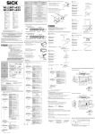
Modell WLL180T-P/N432 M8 4-polig WLL180T-P/N434 Stromverbrauch Die Schaltschwellenanzeige blinkt und das Display zeigt die Grundanzeige. Die Schaltschwellenanzeige blinkt kurz und das Display zeigt die Grundanzeige. Einstellung externer Eingang (Teach-in/Test/Sync) Umgebungstemperatur/Lager +10% Schaltschwelle –25 ... +55 °C/35 ... 85 % RF (kein Frost, keine Kondensation) 2) Umgebungstemperatur/Betrieb Stellt die Schaltschwelle mit +10 % entsprechend dem empfangenen Licht ein. –40 ... +70 °C/35 ... 85 % RF (kein Frost, keine Kondensation) Taster (WT): Auf den Hintergrund ohne und mit Objekt einstellen. 10 ... 55 Hz Doppelamplitude 1,5 mm 2 Std. in jede Richtung x, y, z Schockfestigkeit IP 50 3) Schutzart Gehäusematerial PC Gewicht 3) 1 2 3 0,1 ms–9999 ms Einstellung Eingang 2) S t o P 1 2 3 OFF-Delay, ON-Delay, One-Shot, ON/OFF-Delay, ON-Shot-Delay Ein-/Ausschaltverzögerung 1) Ende: Teach-in-Taste drücken. Infrarot LED Teach-in/Manuelle Einstellung Zeitstufe • Sensor bei abgeschalteter Versorgungsspannung anschließen • Verwenden Sie den Sensor nicht ohne Schutzabdeckung. • Ein Betrieb in folgenden Umgebungen kann zu Fehlfunktionen führen: 1. staubige oder feuchte Umgebung. 2. Bereiche mit korrosiven Gasen. 3. Bereiche mit spritzendem Wasser oder Öl. 4. Bereiche mit stark bewegtem Untergrund. • Verwenden Sie den Sensor nicht im Freien. • Keine Verwendung im Umfeld von Feuer, explosiven Gasen oder brennbaren Flüssigkeiten. • Nicht im Wasser verwenden. • Sensor nicht zerlegen, reparieren oder umbauen. Dieses kann zu Feuer und Elektroschock führen. • Nur im vorgeschriebenen Bereich anwenden. • Verpackung aufbewahren. • Kein Sicherheitsbauteil gemäß EU-Maschinenrichtlinie. S t r t 2-Punkt-Teach-in Leitungstyp: 71 g, M8-Typ: 25 g Zonen-Teach-in Taster 1. Bei vorhandenem Objekt einstellen. Teach-in-Taste für 3 s drücken. 12 ... 24 V DC ± 10 %, Klasse 2 Spannungsversorgung Max. Umgebungstemperatur: +55 °C UL Gehäusetyp 1 Teach-in-Taste für 3 s drücken. Zonen-Teach-in wählen. 2-Punkt-Teach-in wählen. Funktionstasten der Auswerteeinheit Ausgangsanzeige (orange) 2 P t Z o n E 1 P t Teach-in-Taste drücken. 1. Punkt: Teach-in-Taste drücken. Auswahl-Taste 2 P t Verriegelung Lichtleiter 1 P t 2. Auf den Hintergrund ohne Objekt einstellen. 2. Punkt: Teach-in-Taste drücken. 2 P t Anzeige Mode-Taste Z o n E Z o n E g o o d Schwellwert 10% Untere Grenze Fern 2 P t Teach-in-Taste Stellt die Zone mit ±10% entsprechend dem empfangenen Licht ein. 1 2 3 Die Schaltschwellenanzeige blinkt und das Display zeigt die Grundanzeige. Installation der Auswerteeinheit Die Schaltschwellenanzeige blinkt und das Display zeigt die Grundanzeige. Anbringung auf/Entfernen von der Montageschiene Schaltschwelle 2. Legt die Schaltschwelle zwischen 1. und 2. Punkt fest. 2 1 Teach-in transparenter Objekte Entfernen des Sensors: Den Sensor in Richtung schieben, an der Anschlussseite für die Lichtleiter nach oben kippen und Sensor entfernen Schaltkreis Load Anschlussschema NPN 1 Schwarz 4 Weiß 2 Blau 3 Braun 1 Schaltausgang Externer Eingang 4 0V 12~24 V DC Schaltausgang 1 2 3 4 Anschluss-Schema Weiß 2 Blau 3 Externer Eingang 3 Teach-in-Taste drücken. Lichtleiter-Verriegelung öffnen Lichtleiter in vorgesehene Öffnungen bis zum Anschlag einführen Lichtleiter (Ca. 15 mm) Manuelle Einstellung Der Schwellwert wird auf 90% des empfangenen Lichts eingestellt. g L A S 1 g L A S 2 Einwegsystem: Teach-in ohne Objekt durchführen. g o o d Anzeige Sender/Empfänger Bitte beachten Bei koaxialem Lichtleiter, Kern-Lichtleiter oder mit weißer Linie gekennzeichneten Lichtleiter beim Sender einsetzen. Außenliegende Faserbündel/Lichtleiter beim Empfänger einsetzen. Der Schwellwert wird auf 90% des empfangenen Lichts eingestellt. Die Schaltschwellenanzeige blinkt und das Display zeigt die Grundanzeige an. 0V 12 24 V DC Externer Eingang 0V Schaltausgang Diffus: Teach-in ohne Objekt durchführen. Reflektor verwenden. Reflektor g L A S Verbindung der Lichtleiter Lichtleiter-Verriegelung schließen Load Schaltkreis Schwarz Teach-in-Taste für 3 s drücken. 12~24 V DC Schutzkreis Schutzkreis PNP Braun Falls kein Objekt vorhanden, Einstellung in ähnlicher Weise auf Hintergrund 1. Anbringung des Sensors: Den Sensor in die Montageschiene einhaken. Zum Arretieren von oben drücken. Dieser Sensor darf nicht als Sicherheitsgerät verwendet werden, um den menschlichen Körper zu schützen. Nah Obere Grenze 10% Zone ACHTUNG 1 P t Ausgangsanzeige: Orange (Q1) 2 x 4-stellige 7-Segment-Anzeige Empfindlichkeitseinstellung A u t o A u t o rote LED Betriebsanzeige/ Display S t r t Start: Teach-in-Taste drücken. Einwegsystem: Bei vorhandenem Objekt einzustellen. erhalten Lichtquelle Sicherheitshinweise Auto-Teach-in wählen. A u t o Teach-in-Taste drücken. Light on/dark on (hell-/dunkelschaltend) Kurzschlussschutz Taster/Einwegsystem Start und Ende: Automatisches Einstellen im laufenden Prozess. 1-Punkt-Teach-in wählen. 1 P t NPN/PNP Open Collector 100 mA/ ≤ 30 V DC resistiv Laststrom: ≤ 100 mA Restspannung: ≤ 1,8 V Ausgang Vor Inbetriebnahme die Bedienungsanleitung lesen. Warnhinweise sollen Sie vor Gefahren schützen oder helfen Ihnen, eine Beschädigung des Sensors oder der Anlage zu vermeiden. Wenden Sie keine andere Installations- oder Bedienungsprozedur wie hier beschrieben an. Taster: Auf den Hintergrund ohne Objekt einstellen. ≤ 50 mA/24 V Schaltausgang Irrtümer und Änderungen vorbehalten Teach-in-Taste für 3 s drücken. Teach-in-Taste für 3 s drücken. 16 μs/70 μs/250 μs/2 ms/8 ms (schnellste/schnelle/Standard-Einstellung/hohe/superhohe Reichweite) Ansprechzeit WLL180T Auto-Teach-in 1-Punkt-Teach-in WLL180T-P/N474 12 ... 24 V DC inkl. Restwelligkeit 1) Versorgungsspannung 2011-01 GO GO Einstellung Standard Leitungstyp Einsatz von Lichtleitern mit schlanken Endhülsen Lichtleiter mit schlanker Endhülse Adapterstück vollständig gegen den Uhrzeigersinn drehen und Lichtleiter einführen. Verschluss durch Drehung in Uhrzeigersinn. Trennposition Abtrennen des überschüssigen Lichtleiters Drücken Sie eine der Auswahltasten: Die Schaltschwellenanzeige blinkt. Einstellung ist nun möglich. Anpassung über die Auswahltasten. Anpasskappe Normal C A Technische Zeichnung B WLL180T 3 5 0 Fehlerausgabe während des Teach-in Eine Fehlermeldung wird bei fehlerhafter Eingabe während der Einstellung ausgegeben. Siehe nachfolgende Tabelle. E r r 1 Empfangswert ist zu niedrig E r r 2 Empfangswert ist in der Sättigung E r r 3 Differenz zwischen zwei Empfangswerten ist zu klein 4.3 Eco-Modus E c o L o n TOP TOP d 2. Einstellung der Ansprechzeit r E S P L o n g TOP 3. Zeitstufen-Einstellung d E L y TOP o n o n o n 4.4 Anzeige drehen ON - hellschaltend.1) t u r n H i g h Schnellste Einstellung 16 μs F A S t Schnelle Einstellung 70 μs S t n d Standard-Einstellung 250 μs1) L o n g Hohe Reichweite 2 ms S u P r Superhohe Reichweite 8 ms 4.5 Hysterese-Einstellung H y S ON-Delay One-Shot o n o F ON/OFF-Delay o n S h ON-Shot-Delay A S c r S E t n o n o y E S 6. Beenden der Einstellung E n d Zurück zur normalen Anzeige Initialisierung Ext. Teach-in1) t E S t Test-Eingang S y n c Synchronisation o n C Keine Initialisierung 1) r t c h o F F B 7,7 10,5 68,9 3 offener Winkel ca. 180° Sättigung des empfangenen Lichts vermeiden Art der Tastensperre L 1 TOP einstellen. wählen und Die Anzeige kehrt zum Lock-Level-TopMenü zurück. Alle Eingabe-Funktionen L1 gesperrt Alle Eingabe-Funktionen gesperrt außer externer L2 Eingang 2 – Ø 2, 3 18,8 27,8 10 Ø 3,8 4 Adern 2 m 7 Ø 4.10 Ende der Detaileinstellungen (Expert-Modus) E n d 3,55 55,4 4,2 E P r t Kehrt zum Detaileinstellungs-Top-Menü zurück. 3,55 Hinweise zur Funktionseinstellung Stecker M8, 4-polig • 1) bedeutet Werkseinstellung • Nicht verfügbare Einstellungen werden nicht automatisch angezeigt. Dies stellt keine Fehlfunktion dar. • Einstelltaste ca. 0,3 s drücken, falls nichts anderes genannt wird. • Die Hauptanzeige blinkt, wenn die Einstellungs-Auswahl verfügbar ist. • Das Nebendisplay blinkt, wenn die Auswahl verfügbar ist. Optionen Endstück Rückkehr zur Normaleinstellung mit einer Taste Die Taste für zwei Sekunden oder länger gedrückt halten, um zur Normaleinstellung (Betriebsmodus) zurückzukehren ohne den Menüpunkt End zu verwenden. BEF-EB01-W190 5 Einstellen ASC (Automatic Sensitivity Control) wählen und einstellen. Die Anzeige kehrt zum ASC-Einstellmodus zurück. o F F TOP Weiter zur Detaileinstellung. TOP Einstellung geringe Stärke Sperren der Bedienelemente Sperrt alle Eingabe-Funktionen wie in 4.9 ausgewählt (Manipulationsschutz). Beide Tasten im RUN-Mode gleichzeitig zwei Sekunden oder länger drücken. Zum Entsperren analog verfahren (Manipulationsschutz). Sperrung L o c Entsperrung 3 0 0 u n L c 3 0 0 SAM Circuit (ASC = Automatic Sensitivity Control) 4.7 ASC-Einstellung TIPP Rücksetzen aller Einstellungen. wählen und einstellen. Die Anzeige kehrt zum Initialisierungs-TopMenü zurück. Hysterese-Einstellung wählen. wählen und einstellen. Einstellung mittlere Stärke ¦¦ Die Anzeige kehrt zum Extern-Eingangsfunktion-Top-Menü zurück. 0 0 0 1 A Anzeige „auf dem Kopf“ Auswahl: Funktion des ext. Eingangs einstellen. wählen und Eingang I n P t 4. Detaileinstellungen (Expertenmodus) TOP Anzeige normal o n gilt für Zahlenwechsel und ist zur Einstellung. Die Anzeige kehrt zum Hysterese-Top-Menü zurück. 4.6 Eingangs-Einstellung ist für Zeitstufenwechsel und ist zur Einstellung. Danach kehrt die Anzeige zum ZeitstufenTop-Menü zurück. E P r t 1) o f f TOP Zeitstufen von 0,1–9999 (0,1 ms–9999 ms) wählbar o F d y Stromsparmodus aktiviert P OFF-Delay S h o t Stromsparmodus deaktiviert1) Zahlenbereich 1 … 40% vom Sollwert. Keine Zeitstufe aktiviert1) o n d y P 5 TOP Zeitstufe wählen. wählen und einstellen. OFF wechselt zur Ausgangsanzeige zurück. o F F Prozentuale Anzeige Display-Anzeige wird gedreht. wählen und einstellen. Die Anzeige kehrt zum Turn-Top-Menü zurück. o f f TOP ON - dunkelschaltend. 4.9 Lock-Level L o c L Display wird nach 20 s abgeschaltet. Aktivieren durch Drücken einer beliebigen Taste. Die Ansprechzeit wählen. wählen und einstellen. Die Anzeige kehrt zum Ansprechzeit-TopMenü zurück. o F d y 5. Reset Balken-Anzeige o f f Den Betriebsmodus auswählen. wählen und einstellen. Die Anzeige kehrt zum BetriebseinstellungsTop-Menü zurück. L Numerische Anzeige1) TIPP Stromsparmodus aktivieren. wählen und einstellen. Die Anzeige kehrt zum Eco-Top-Menü zurück. o f f Die Mode-Taste für 3 s drücken. L – – d d I g b A r P c t Funktionseinstellung 1. Betriebseinstellung Eine Darstellung der Display-Einstellungen wählen. wählen und einstellen. Die Anzeige kehrt zum Display-Top-Menü zurück. Einstellung Standard1) ¦¦¦¦ Ø 8,6 TOP ¦¦¦¦¦¦ (Maßeinheit: mm) 16,1 d I g TOP Nullwert- Einstellung einschalten. 37,3 10,4 d I S P 12,2 wählen und einstellen. Die Anzeige kehrt zum Nullwert-Top-Menü. Ø 8,6 4.2 Display-Einstellungen Nullwert- Einstellung ausschalten.1) Beleuchtungsstärke kann in drei Stufen gewählt werden. 33,2 o n ¦¦¦¦¦¦ S P o r 34,6 o F F 4.8 Einstellung der Stärke der Sende-LED 4,3 TOP 8 o F S t Kehrt automatisch in die Normaldarstellung nach 5 Sekunden nach Beendigung der Einstellung zurück (kein Betrieb). Anzeigewert der Hauptanzeige auf „0“ stellen. wählen und einstellen. Die Anzeige kehrt zum Nullwert-Top-Menü zurück. 8 4.1 Displaywert auf Null setzen. 5,7 3 0 0 ASC ausschalten1) Schwellwert automatisch an Umgebung anpassen. Schwellwert-Einstellung vorzugsweise nach Reinigung. Schwellenwert wird automatisch zurückgesetzt, während der Sensor laufend das empfangene Licht prüft. Ein plötzlicher Wechsel der Lichtmenge wie z. B. die Reinigung der Linse, stellt den Schwellenwert zurück. Externer Teach-in Der Teach-in-Eingang (ET) muss für > 200 ms aktiviert werden um einen Teach-in-Vorgang durchzuführen (ET an > 10 V ... < UV für PNP-Geräte; ET an 0 V für NPN-Geräte). Änderungen vorbehalten. Für weitergehende Informationen bzgl. Konfigurationsmenü und Teach-inFunktionen siehe Anwenderhandbuch oder www.sick.com. Model WLL180T-P/N432 M8 4-pin WLL180T-P/N434 Consumption current NPN/PNP open collector 100 mA/ ≤ 30 V DC resistive Load current: ≤ 100 mA Residual voltage ≤ 1.8 V 1 P t Control output Light on/Dark on Switching type in the function 1 P t Red LED Sensitivity setting CAUTION +10% Threshold Set the threshold to +10 % adjust the amount of received light. –25 ... +55 °C/35 ... 85 % RF (No freezing and no condensation) 2) Store temperature/humidity –40 ... +70 °C/35 ... 85 % RF (No freezing and no condensation) 10 ... 55 Hz amplitude 1.5 mm 2 hours for each direction x, y, z Reflection type: Perform adjustment with background without object or when there is an object. Zone Teach-in IP 50 3) 2-Point Teach-in Material PC Weight Cable type: 71 g, M8 Connector type: 25 g 3) S t o P The threshold flashes and the display returns to normal. The threshold flashes and the display returns to normal. External input setting (Teach-in/Test/Sync) Operating temperature/humidity 2) End: Press the Teach-in button. 1 2 3 0, 1 ms–9999 ms Setting input 1) S t r t 1 2 3 Off delay, On delay, One shot, On/Off delay, On shot delay Timer time Shock resistance • It is dangerous to wire or attach/remove the connector with the power on. Make sure to turn off the power before operation. • Make sure to use the product with the protective cover attached and closed. • Installing in the following places may result in malfunction: 1. A dusty or steamy place. 2. A place generating corrosive gas. 3. A place directly receiving scattering water or oil. 4. A place suffered from heavy vibration or impact. • The product is not designed for outdoor use. • This product is not an explosion-proof construction. Do not use the product under flammable, explosive gas or liquid environment. • Do not use the product in water. • Do not disassemble, repair, or convert the product. Failure to do this may cause failure, fire, or electric shock. • Operate within the rated range. • Keep the packing box carefully. • No safety component in accordance with EU machine guidelines. A u t o A u t o IR LED Protective category Press the Teach-in button. Teach-in/Manual adjustment Timer function Safety Precautions Start: Press the Teach-in button. Through beam type: Perform adjustment when there is an object. Output indicator light: Orange (Q1) 7-segment 8-digit display Indicator light/ Display Carefully read and understand the safety precautions before operation. The important information is provided to protect your health and property. Do not apply any other installing or operating procedure other than that described in these operating instructions. S t r t Select the 1-Point Teach-in. Incorporated Light source Through beam type/Reflection type Start and End: Perform adjustment while the object is passing. Select the auto Teach-in. A u t o Response time Short-circuit protection Subject to change without notice Reflection type: Perform adjustment when the background without object. ≤ 50 mA/24 V 16 μs/70 μs/250 μs/2 ms/8 ms (fastest/fast/standard setting/high accuracy/super long range) Output method WLL180T Press Teach-in button for 3 sec. Reflection type 1st: Perform adjustment when there is an object. Press Teach-in button for 3 sec. 12 ... 24 V DC ± 10 %, class 2 power supply Max. ambient temperature: +55 °C UL enclosure Type 1 Press Teach-in button for 3 sec. Select the zone Teach-in. Z o n E Select the 2-Point Teach-in. 2 P t 1 P t Each Part Press the Teach-in button. 1. Point: Press the Teach-in button. Output Indicator (Orange) 2 P t Select Button Lock Lever Z o n E 1 P t 2nd: Perform adjustment background without object. 2. Point: Press the Teach-in button. 2 P t Z o n E Near Upper limit 10% Threshold Sensing Level Threshold g o o d 10% Lower Far 2 P t Zone 2011-01 GO GO Press Teach-in button for 3 sec. 1-Point Teach-in WLL180T-P/N474 12 ... 24 V DC including a ripple 1) Power source, voltag Auto-Teach-in Adjustment Standard type Cable type Set the zone (detection range) to ±10%. Display Mode Button Teach-in Button 1 2 3 Through beam type/Reflection type: Execute Teach-in without objekt. The threshold flashes and the display returns to normal. Installation of Amplifier The threshold flashes and the display returns to normal. 1st Threshold Attaching and removing to/from DIN rail 2nd Attachment of sensor unit: Hook the claw on the connecting side of fiber cable to the DIN rail. Then press down the hook until it locks. Set the threshold at the center between the 1st and 2nd points. Diffuse type: Execute Teach-in without objekt. Use reflector. Reflector Press Teach-in button for 3 sec. Removal of sensor unit: Pushing the unit to the direction of, hold up the connecting side of fiber cable and remove the unit. This product must not be used as a safety device to protect human body. Teach-in transparent object 2 1 g L A S 3 Press the Teach-in button. How to connect the fiber cables Input/Output Schematic Main circuit Load Brown 4 2 Blue 3 Brown 1 Black 4 White 2 Blue 3 Control output Open fiber lock lever. Insert fiber into holes to stop. g L A S Return fiber lock lever until it stops. Insertion sign of Fiber cable External input Fine fiber Turn adapter cap anticlockwise completely, then appropriately insert the fiber. Be locked by turning adapter cap clockwise. Cut the excess fiber with fiber cutter. Cut position Adapter cap C o F F o n 3 5 0 Turn off Zero reset.1) 4.8 Floodlight power setting ¦¦¦¦¦¦ S P o r Light intensitiy can be chosen from the three levels. TOP ¦¦¦¦¦¦ Turn on Zero reset. ¦¦¦¦ Select a display method of normal main sub monitor. and fix by . Select by using The screen returns to the top of display setting. 4.2 Display setting Automatically returns to the normal display 5 seconds after completion of the setting (no operation). d I S P d I g TOP 4.3 Eco mode Error display in Teach-in E c o An error message is displayed in the event of error during adjustment. Refer to the table below for readjustment. E r r 2 Sensing level is saturated E r r 3 Difference of sensing level between two points is too small 4.4 Reverse display t u r n TOP 2. Response speed setting r E S P L o n g TOP Select an operation mode. Select by using and fix by . The screen returns to the top of operation setting. L o n ON when light comes in.1) d o n ON when light is blocked. Fastest setting 16 μs F A S t Fast setting 70 μs S t n d Standard setting 250 μs 1) L o n g High accuracy 2 ms S u P r 3. Timer setting d E L y TOP 4.5 Hysteresis setting H y S Select a response speed. and fix by . Select by using The screen returns to the top of response speed setting. H i g h Off delay On delay 4.6 Input setting t E S t Test input S y n c Synchronization o n n o y E S TOP TIPP 6. End of setting E n d Returns to the normal display. Initialize L2 2 All inputs locked – Ø 2. 3 All inputs locked, except external input 18.8 10 Ø 3.8 4 core 2 m 7 Ø 4.10 End of Detail Setting (Expert mode) 55.4 4.2 E P r t Returns to the top of detail setting (Expert mode). 3.55 Precautions for function setting M8 4-pin connector C B Options Returning to normal display with one button Pressing the button for 2 seconds or more in setting a function returns to normal display (RUN mode) without using the menue point End. . Hold down the buttons for 2 seconds or more simultaneously in the RUN mode. Operate in the same way to cancel as well. In locking L o c When cancelled 3 0 0 u n L c Non-use of ASC 1) Automatically adjust threshold along with the surroundings Automatically set threshold even after sensors are cleaned. BEF-EB01-W190 Specifications and equipment are subject to change without any obligations on the part of manufacture. For further information regarding configuration menue and Teach-in function please take note of the application manual or www.sick.com. Key lock Locks all inputs according to the selected level in 4.11. Useful to prevent accidental operation. 3 0 0 Threshold value will be automatically reset as the sensor continuously monitors returned light. Sudden change of returned light, like cleaning of lens, will trigger reset of the best threshold computed in the circuit (SAM circuit). External Teach-in The external teach-input must be activated for > 200 ms to perform a teach-in (ET to > 10 V ... < UV for PNP devices; ET to 0 V for NPN devices). 0 0 0 1 Not initialize 1) . Set up ASC (Automatic Sensitivity Control). and fix by . Select by using Return to the top of ASC setting. o F F o F F Reset all settings to the factory default. and fix by . Select by using The screen returns to the top of initialization setting. Open angle approx. 180° Select by using and fix by . Return to the top of lock level setting. L1 E n d 3.55 Key-lock level L 1 SAM Circuit (ASC = Automatic Sensitivity Control) 4.7 ASC setting On shot delay Moves to the detailed setting menu. 68.9 3 Avoid saturation of the amount of light received. The screen returns to the top of extern input function setting. o n S h A 10.5 Set in the low power • 1) means factory default setting • Unavailable settings are not indicated automatically These are not any troubles and failures. • Hold down the operation button for approx. 0.3 seconds if not especially specified. • The sub monitor starts flashing when each setting selection becomes available. 5 Ext. Teach-in 1) On/Off delay Settings are only for tuning on (ON) or turning off (OFF). Set in the middle power End Unit and fix by r t c h One shot E P r t n o Display upside-down o n o F TOP r S E t Normal display 1) o n S h o t o F d y TOP o f f Selection of input function. and fix by Select by using Input I n P t TOP Timer time setting 0, 1–9999 (0,1 ms–9999 ms) is for time changing and is to fix. Then the screen returns to timer setting top. 5. Initialization setting (Initial reset) Activate energy saving mode P A S c 4. Detailed setting (Expert mode) o n Hysteresis 1 … 40% of nominal value. Timer off 1) o n d y Set on standard 1) 27.8 Deactivate energy saving mode1) is for value change, and is to fix. The screen returns to the top of hysteresis setting. Select a timer and the time. and fix by . Select by using OFF moves to the top of timer setting and others move to the timer setting. o F F L o c L . o f f Select hysteresis. Select by using P 5 TOP Super long range 8 ms o F d y Displayed in percent (%) display. 4.9 Lock Level TOP Display is reversed. and fix by . Select by using The screen returns to the top of reverse display setting. o f f TOP o n P c t TIPP (Unit: mm) Display is switched off after 20 sec. To activate press any button. Press the mode button for 3 sec. L Displayed in bar display. Activate energy saving mode. and fix by Select by using The screen returns to the top of eco mode setting o f f TOP Function Setting L – – d Displayed in numeric display.1) ¦¦ 37.3 10.4 Sensing level is too low d I g b A r 12.2 and fix by . Select by using Return to the of floodlight power setting. Ø 8.6 TOP 16.1 o F S t Normal WLL180T Ø 8.6 4.1 Zero-reset setting Dimensional Drawing B 7.7 Set the displayed value on the main monitor to „0.“ and fix by . Select by using The screen returns to the top of zero reset setting. 33.2 A 34.6 Manual adjustment E r r 1 Threshold is set at 90% of returned light level. How to use fine fiber External input 0V The threshold flashes and the display returns to normal. 4.3 12~24 V DC Control output With Coaxial reflection fiber, set single core fiber or white-lined fiber to the emitter. Then set Multi wick fiber to the receiver. 8 12 24 V DC External Input 0V Control output CAUTION 0V Pressing the select button flashes the threshold. It indicates that adjustment is possible. Adjust to any value using the select buttons. 1. Operation setting Through beam type/Reflection type: Execute Teach-in without objekt. g o o d 2 8 Load Main circuit 1 2 3 4 Pin layout 3 0 0 1 Fiber cable (Approximately 15 mm) Protection Circuit Protection Circuit PNP Black White 12~24 V DC 5.7 NPN 1 Threshold is set at 90% of returned light level. g L A S