1
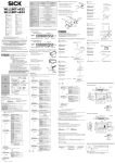
Model WLL180T-P/N432 M8 4-pin WLL180T-P/N434 Consumption current NPN/PNP open collector 100 mA/ ≤ 30 V DC resistive Load current: ≤ 100 mA Residual voltage ≤ 1.8 V 1 P t Control output Light on/Dark on Switching type in the function 1 P t Red LED Sensitivity setting CAUTION +10% Threshold Set the threshold to +10 % adjust the amount of received light. –25 ... +55 °C/35 ... 85 % RF (No freezing and no condensation) 2) Store temperature/humidity –40 ... +70 °C/35 ... 85 % RF (No freezing and no condensation) 10 ... 55 Hz amplitude 1.5 mm 2 hours for each direction x, y, z Reflection type: Perform adjustment with background without object or when there is an object. Zone Teach-in IP 50 3) 2-Point Teach-in Material PC Weight Cable type: 71 g, M8 Connector type: 25 g 3) S t o P The threshold flashes and the display returns to normal. The threshold flashes and the display returns to normal. External input setting (Teach-in/Test/Sync) Operating temperature/humidity 2) End: Press the Teach-in button. 1 2 3 0, 1 ms–9999 ms Setting input 1) S t r t 1 2 3 Off delay, On delay, One shot, On/Off delay, On shot delay Timer time Shock resistance • It is dangerous to wire or attach/remove the connector with the power on. Make sure to turn off the power before operation. • Make sure to use the product with the protective cover attached and closed. • Installing in the following places may result in malfunction: 1. A dusty or steamy place. 2. A place generating corrosive gas. 3. A place directly receiving scattering water or oil. 4. A place suffered from heavy vibration or impact. • The product is not designed for outdoor use. • This product is not an explosion-proof construction. Do not use the product under flammable, explosive gas or liquid environment. • Do not use the product in water. • Do not disassemble, repair, or convert the product. Failure to do this may cause failure, fire, or electric shock. • Operate within the rated range. • Keep the packing box carefully. • No safety component in accordance with EU machine guidelines. A u t o A u t o IR LED Protective category Press the Teach-in button. Teach-in/Manual adjustment Timer function Safety Precautions Start: Press the Teach-in button. Through beam type: Perform adjustment when there is an object. Output indicator light: Orange (Q1) 7-segment 8-digit display Indicator light/ Display Carefully read and understand the safety precautions before operation. The important information is provided to protect your health and property. Do not apply any other installing or operating procedure other than that described in these operating instructions. S t r t Select the 1-Point Teach-in. Incorporated Light source Through beam type/Reflection type Start and End: Perform adjustment while the object is passing. Select the auto Teach-in. A u t o Response time Short-circuit protection Subject to change without notice Reflection type: Perform adjustment when the background without object. ≤ 50 mA/24 V 16 μs/70 μs/250 μs/2 ms/8 ms (fastest/fast/standard setting/high accuracy/super long range) Output method WLL180T Press Teach-in button for 3 sec. Reflection type 1st: Perform adjustment when there is an object. Press Teach-in button for 3 sec. 12 ... 24 V DC ± 10 %, class 2 power supply Max. ambient temperature: +55 °C UL enclosure Type 1 Press Teach-in button for 3 sec. Select the zone Teach-in. Z o n E Select the 2-Point Teach-in. 2 P t 1 P t Each Part Press the Teach-in button. 1. Point: Press the Teach-in button. Output Indicator (Orange) 2 P t Select Button Lock Lever Z o n E 1 P t 2nd: Perform adjustment background without object. 2. Point: Press the Teach-in button. 2 P t Z o n E Near Upper limit 10% Threshold Sensing Level Threshold g o o d 10% Lower Far 2 P t Zone 2011-01 GO GO Press Teach-in button for 3 sec. 1-Point Teach-in WLL180T-P/N474 12 ... 24 V DC including a ripple 1) Power source, voltag Auto-Teach-in Adjustment Standard type Cable type Set the zone (detection range) to ±10%. Display Mode Button Teach-in Button 1 2 3 Through beam type/Reflection type: Execute Teach-in without objekt. The threshold flashes and the display returns to normal. Installation of Amplifier The threshold flashes and the display returns to normal. 1st Threshold Attaching and removing to/from DIN rail 2nd Attachment of sensor unit: Hook the claw on the connecting side of fiber cable to the DIN rail. Then press down the hook until it locks. Set the threshold at the center between the 1st and 2nd points. Diffuse type: Execute Teach-in without objekt. Use reflector. Reflector Press Teach-in button for 3 sec. Removal of sensor unit: Pushing the unit to the direction of, hold up the connecting side of fiber cable and remove the unit. This product must not be used as a safety device to protect human body. Teach-in transparent object 2 1 g L A S 3 Press the Teach-in button. How to connect the fiber cables Input/Output Schematic Main circuit Load Brown 4 2 Blue 3 Brown 1 Black 4 White 2 Blue 3 Control output Open fiber lock lever. Insert fiber into holes to stop. g L A S Return fiber lock lever until it stops. Insertion sign of Fiber cable External input Fine fiber Turn adapter cap anticlockwise completely, then appropriately insert the fiber. Be locked by turning adapter cap clockwise. Cut the excess fiber with fiber cutter. Cut position Adapter cap C o F F o n 3 5 0 Turn off Zero reset.1) 4.8 Floodlight power setting ¦¦¦¦¦¦ S P o r Light intensitiy can be chosen from the three levels. TOP ¦¦¦¦¦¦ Turn on Zero reset. ¦¦¦¦ Select a display method of normal main sub monitor. and fix by . Select by using The screen returns to the top of display setting. 4.2 Display setting Automatically returns to the normal display 5 seconds after completion of the setting (no operation). d I S P d I g TOP 4.3 Eco mode Error display in Teach-in E c o An error message is displayed in the event of error during adjustment. Refer to the table below for readjustment. E r r 2 Sensing level is saturated E r r 3 Difference of sensing level between two points is too small 4.4 Reverse display t u r n TOP 2. Response speed setting r E S P L o n g TOP Select an operation mode. Select by using and fix by . The screen returns to the top of operation setting. L o n ON when light comes in.1) d o n ON when light is blocked. Fastest setting 16 μs F A S t Fast setting 70 μs S t n d Standard setting 250 μs 1) L o n g High accuracy 2 ms S u P r 3. Timer setting d E L y TOP 4.5 Hysteresis setting H y S Select a response speed. and fix by . Select by using The screen returns to the top of response speed setting. H i g h Off delay On delay 4.6 Input setting t E S t Test input S y n c Synchronization o n n o y E S TOP TIPP 6. End of setting E n d Returns to the normal display. Initialize L2 2 All inputs locked – Ø 2. 3 All inputs locked, except external input 18.8 10 Ø 3.8 4 core 2 m 7 Ø 4.10 End of Detail Setting (Expert mode) 55.4 4.2 E P r t Returns to the top of detail setting (Expert mode). 3.55 Precautions for function setting M8 4-pin connector C B Options Returning to normal display with one button Pressing the button for 2 seconds or more in setting a function returns to normal display (RUN mode) without using the menue point End. . Hold down the buttons for 2 seconds or more simultaneously in the RUN mode. Operate in the same way to cancel as well. In locking L o c When cancelled 3 0 0 u n L c Non-use of ASC 1) Automatically adjust threshold along with the surroundings Automatically set threshold even after sensors are cleaned. BEF-EB01-W190 Specifications and equipment are subject to change without any obligations on the part of manufacture. For further information regarding configuration menue and Teach-in function please take note of the application manual or www.sick.com. Key lock Locks all inputs according to the selected level in 4.11. Useful to prevent accidental operation. 3 0 0 Threshold value will be automatically reset as the sensor continuously monitors returned light. Sudden change of returned light, like cleaning of lens, will trigger reset of the best threshold computed in the circuit (SAM circuit). External Teach-in The external teach-input must be activated for > 200 ms to perform a teach-in (ET to > 10 V ... < UV for PNP devices; ET to 0 V for NPN devices). 0 0 0 1 Not initialize 1) . Set up ASC (Automatic Sensitivity Control). and fix by . Select by using Return to the top of ASC setting. o F F o F F Reset all settings to the factory default. and fix by . Select by using The screen returns to the top of initialization setting. Open angle approx. 180° Select by using and fix by . Return to the top of lock level setting. L1 E n d 3.55 Key-lock level L 1 SAM Circuit (ASC = Automatic Sensitivity Control) 4.7 ASC setting On shot delay Moves to the detailed setting menu. 68.9 3 Avoid saturation of the amount of light received. The screen returns to the top of extern input function setting. o n S h A 10.5 Set in the low power • 1) means factory default setting • Unavailable settings are not indicated automatically These are not any troubles and failures. • Hold down the operation button for approx. 0.3 seconds if not especially specified. • The sub monitor starts flashing when each setting selection becomes available. 5 Ext. Teach-in 1) On/Off delay Settings are only for tuning on (ON) or turning off (OFF). Set in the middle power End Unit and fix by r t c h One shot E P r t n o Display upside-down o n o F TOP r S E t Normal display 1) o n S h o t o F d y TOP o f f Selection of input function. and fix by Select by using Input I n P t TOP Timer time setting 0, 1–9999 (0,1 ms–9999 ms) is for time changing and is to fix. Then the screen returns to timer setting top. 5. Initialization setting (Initial reset) Activate energy saving mode P A S c 4. Detailed setting (Expert mode) o n Hysteresis 1 … 40% of nominal value. Timer off 1) o n d y Set on standard 1) 27.8 Deactivate energy saving mode1) is for value change, and is to fix. The screen returns to the top of hysteresis setting. Select a timer and the time. and fix by . Select by using OFF moves to the top of timer setting and others move to the timer setting. o F F L o c L . o f f Select hysteresis. Select by using P 5 TOP Super long range 8 ms o F d y Displayed in percent (%) display. 4.9 Lock Level TOP Display is reversed. and fix by . Select by using The screen returns to the top of reverse display setting. o f f TOP o n P c t TIPP (Unit: mm) Display is switched off after 20 sec. To activate press any button. Press the mode button for 3 sec. L Displayed in bar display. Activate energy saving mode. and fix by Select by using The screen returns to the top of eco mode setting o f f TOP Function Setting L – – d Displayed in numeric display.1) ¦¦ 37.3 10.4 Sensing level is too low d I g b A r 12.2 and fix by . Select by using Return to the of floodlight power setting. Ø 8.6 TOP 16.1 o F S t Normal WLL180T Ø 8.6 4.1 Zero-reset setting Dimensional Drawing B 7.7 Set the displayed value on the main monitor to „0.“ and fix by . Select by using The screen returns to the top of zero reset setting. 33.2 A 34.6 Manual adjustment E r r 1 Threshold is set at 90% of returned light level. How to use fine fiber External input 0V The threshold flashes and the display returns to normal. 4.3 12~24 V DC Control output With Coaxial reflection fiber, set single core fiber or white-lined fiber to the emitter. Then set Multi wick fiber to the receiver. 8 12 24 V DC External Input 0V Control output CAUTION 0V Pressing the select button flashes the threshold. It indicates that adjustment is possible. Adjust to any value using the select buttons. 1. Operation setting Through beam type/Reflection type: Execute Teach-in without objekt. g o o d 2 8 Load Main circuit 1 2 3 4 Pin layout 3 0 0 1 Fiber cable (Approximately 15 mm) Protection Circuit Protection Circuit PNP Black White 12~24 V DC 5.7 NPN 1 Threshold is set at 90% of returned light level. g L A S