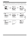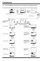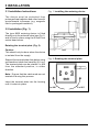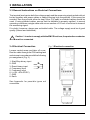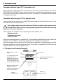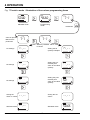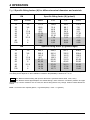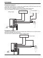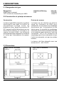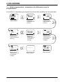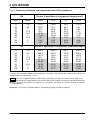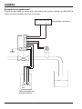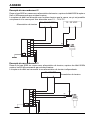
1
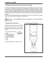
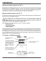
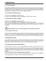
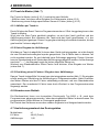
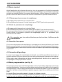
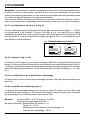
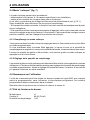
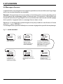
8600
BEDIENUNGSANLEITUNG IN DEUTSCH ................................................................... 2
INSTRUCTION MANUAL IN ENGLISH ....................................................................... 10
NOTICE D'UTILISATION EN FRANCAIS ................................................................... 18
Beratung und Service ................................................................................................ 26
Advice and service ..................................................................................................... 26
Conseil et service après-vente ................................................................................. 26
*****
©BÜRKERT 1996 TR419573U-607-1-RM
Technische Änderungen vorbehalten
We reserve the right to make technical changes without notice
Sous réserve de modifications techniques
8600
-1-
INHALTSVERZEICHNIS
1
1.1
1.2
1.3
1.4
EINFÜHRUNG ....................................................................................................... 3
Auspacken und Kontrolle ...................................................................................... 3
Allgemeine Hinweise ............................................................................................. 3
Sicherheitshinweise ............................................................................................... 3
Elektromagnetische Verträglichkeit ....................................................................... 3
2
2.1
2.2
2.3
2.4
BESCHREIBUNG.................................................................................................. 4
Typenbezeichnung ................................................................................................ 4
Aufbau und Messprinzip ........................................................................................ 4
Abmessungen ........................................................................................................ 4
Technische Daten .................................................................................................. 5
3
3.1
3.2
3.3
3.4
INSTALLATION .................................................................................................... 6
Allgemeine Hinweise zum Einbau ......................................................................... 6
Einbau .................................................................................................................... 6
Allgemeine Hinweise zum elektrischen Anschluss ............................................... 7
Elektrischer Anschluss .......................................................................................... 7
4
4.1
4.2
BEDIENUNG ......................................................................................................... 8
Anzeige- und Bedienelemente .............................................................................. 8
Standardmodus ..................................................................................................... 9
4.2.1 Starten des Abfüllvorgangs .......................................................................... 9
4.2.2 Stoppen des Abfüllvorgangs ........................................................................ 9
4.2.3 Einlegen einer Pause ................................................................................... 9
Nachlaufkorrektur .................................................................................................. 9
Programmiermodus ............................................................................................... 9
4.4.1 Der Multiplikator des K-Faktors.................................................................. 10
4.4.2 Der K-Faktor ............................................................................................... 10
4.4.3 Der Multiplikator der Abfüllmenge .............................................................. 10
4.4.4 Die Abfüllmenge ......................................................................................... 10
Teach-In-Modus .................................................................................................. 10
4.5.1 Abfüllen per Teach-In ................................................................................. 11
4.5.2 Keine Eingabe der Abfüllmenge ................................................................ 11
4.5.3 Ermittlung eines K-Faktors / Eingabe der Abfüllmenge............................. 11
Hinweise zum Betrieb .......................................................................................... 11
Auslieferungszustand des Dosiergerätes ........................................................... 11
Fehlermeldungen ................................................................................................. 12
4.3
4.4
4.5
4.6
4.7
4.8
ANHANG: Anschlussmöglichkeiten ......................................................................... 16
8600
-2-
1 EINFÜHRUNG
Sehr geehrter Kunde,
1.3 Sicherheitshinweise
wir beglückwünschen Sie zum Kauf unseres
kompakten Dosiergerätes 8600. Sie haben
eine gute Wahl getroffen. Um die vielfältigen
Vorteile, die Ihnen das Produkt bietet, voll
nutzen zu können, befolgen Sie bitte
unbedingt unseren Rat und
Bürkert stellt verschiedene Dosiergeräte
her. Jedes kann in einer Vielfalt von
Applikationen eingesetzt werden. Gerne
beraten wir Sie hierzu. Es liegt jedoch in der
Verantwortung des Kunden, das zu seiner
Applikation optimal passende Gerät zu
wählen, es korrekt zu installieren und
instandzuhalten.
LESEN SIE DIESE BEDIENUNGSANLEITUNG GRÜNDLICH, BEVOR SIE
DAS GERÄT MONTIEREN UND IN
BETRIEB NEHMEN.
Dieses Symbol erscheint in der
Bedienungsanleitung jedesmal
wenn besondere Vorsicht
geboten ist, um eine einwandfreie
Installation, Funktion und Betriebssicherheit
des Gerätes zu gewährleisten.
!
1.1 Auspacken und Kontrolle
Bitte überprüfen Sie die Lieferung auf
Vollständigkeit und Transportschäden. Zur
Standardlieferung gehören:
1.4 Elektromagnetische
Verträglichkeit
-1Stück Dosiergerät Typ 8600
-1Stück Bedienungsanleitung
Hiermit wird bestätigt, dass dieses Produkt
den wesentlichen Schutzanforderungen
entspricht, die in der Richtlinie des Rates
zur Angleichung der Rechtsvorschrifften der
Mitgliedstaaten über elektromagnetische
Verträglichkeit (89/336/EWG) festgelegt
sind.
Bei Verlust oder Schäden wenden Sie sich
an Ihre Bürkert Niederlassung.
1.2 Allgemeine Hinweise
Diese Druckschrift enthält keine
Garantiezusagen. Wir verweisen hierzu auf
unsere allgemeinen Verkaufs- und Lieferbedingungen.
Einbau und/oder Reparatur dürfen nur durch
eingewiesenes Personal erfolgen. Sollten
bei der Installation oder der Inbetriebnahme
Schwierigkeiten auftreten, setzen Sie sich
bitte sofort mit unserer nächsten
Niederlassung in Verbindung.
8600
-3-
2 BESCHREIBUNG
2.1 Typenbezeichnung
Bezeichnung
8600 Kompaktes Dosiergerät
1077-4 Bedieneinheit für 8600
Kabeldurchführung
PG9
Ident Nr.
130429W
130447Y
2.2 Aufbau und Messprinzip
Aufbau
Messprinzip
Das Dosiergerät Typ 8600 besteht aus einer
Elektronik in einem spritzwassergeschützten Kunststoffgehäuse, Schutzart
IP65. Das Gerät wird direkt auf ein Bürkert
Magnetventil gesteckt und an einen
Durchfluss-Sensor 8020 angeschlossen.
Die verschiedenen Anschlüsse erfolgen auf
einer 7-poligen Anschlussklemme über eine
PG 9-Kabeldurchführung.
Das Dosiergerät ist eine Schnittstelle die
das Frequenzsignal des 8020 verwendet
um ein Abfüllvorgang direkt über ein
Magnetventil zu steuern. Die Abfüllmenge
und der K-Faktor (abhängig von
Rohrdurchmesser und Material) werden
mittels der Bedieneinheit 1077-4
eingegeben. Die Steuerung eines
Abfüllvorgangs kann entweder über die
Bedieneinheit oder über die Binäreingänge
erfolgen.
Das Dosiergerät benötigt zum Betrieb eine
Spannungsversorgung von 24...48 V
AC/DC.
2.3 Abmessungen
Ohne Bedieneinheit 1077-4
8600
Mit Bedieneinheit 1077-4
-4-
3 INSTALLATION
2.4 Technische Daten
Umgebungstemperatur
Lagertemperatur
Relative Luftfeuchtigkeit
Schutzart
-10 bis 60°C (14 bis 140°F)
-10 bis 80°C (14 bis 176°F)
80 %
IP 65
Signaleingang
Signalart
Genauigkeit
Eingangswiderstand
Binäreingänge: Schaltzeit
Frequenzeingang 1...500 Hz
Sinus/Rechteck/Dreieck (>300 mVss)
+/- 1 Impuls
>10 kΩ
ca. 0,5 - 1 Sek.
Anschluss
7-polige Klemmleiste + PE
Drahtquerschnitt max. 0,5 mm2
Spannungsversorgung
24...48 V AC/DC
!
Achtung!: Die Anschluss-Spannung und die Stromart muss immer gleich den
Anschlusswerten des Magnetventils sein.
Gehäuse Werkstoff
PA
Gewicht
ca. 50 g
8600
-5-
3 INSTALLATION
3.1 Hinweise zum Einbau
Abb.1 Einbau Dosiergerät
Das Gerät ist vor Dauerwärmestrahlung und
anderen störenden Umwelteinflüssen zu
schützen (z.B. Magnetfelder oder Dauersonnenbestrahlung).
3.2 Einbau (Abb. 1)
Das Dosiergerät Typ 8600 wird direkt auf
das Magnetventil gesteckt (siehe Abb.1) und
durch die Zylinderschraube M 3x45 mm,
festgeschraubt.
Drehen der Anschlussplatte (Abb. 2)
Achtung:
Nur im spannungsfreien Zustand!
Mit der Schraubendreherklinge unterfassen
und die Anschlussplatte vorsichtig
aushebeln. Die Anschlussplatte ist um 2 x
90°, von der Standardposition ab, in jede
Richtung drehbar.
Abb. 2 Drehen der Anschlussplatte
Hinweis: Die Kabelenden dabei nicht
abdrehen!
Die Anschlussplatte ins Gehäuse einsetzen
bis sie einrastet.
2 x 90°
8600
-6-
2 x 90°
3 INSTALLATION
3.3 Allgemeine Hinweise zum elektrischen Anschluss
Die Anschlussleitung führt die Spannungsversorgung und das Mess-Signal und darf nicht
zusammen mit Starkstromleitungen oder Hochfrequenz führenden Leitungen verlegt
werden. Ist eine Zusammenverlegung unvermeidlich, so ist ein Mindestabstand von 30 cm
(1 ft) einzuhalten oder abgeschirmte Leitung zu verwenden. Bei abgeschirmten Leitungen
ist darauf zu achten, dass die Abschirmung einwandfrei geerdet ist. Bei normalen Betriebsbedingungen genügt einfaches Kabel mit Querschnitt 0,5 mm2 zur Übertragung des MessSignales.
Im Zweifelsfall jedoch stets abgeschirmtes Kabel verwenden. Die Spannungsversorgung
muss von guter Qualität sein (gefiltert und stabilisiert).
!
Achtung!: Um die EMV-Richtlinien einzuhalten ist der Schutzleiter
anzuschliessen.
3.4 Elektrischer Anschluss
Abb. 3 Elektrischer Anschluss
Zentralschraube lösen und Deckel
abnehmen. Das Kabel durch die PG 9Verschraubung führen und gemäss
folgender Anschlussbelegung beschalten
(Abb. 3):
1: Binäreingang Start/Stop
2: GND
3: Binäreingang Reset
4: Frequenzeingang
5: Frequenzeingang
6: L+(24...48V AC/DC)
7: GND
8: Erde
Anschlussmöglichkeiten: siehe Anhang
8600
-7-
4 BEDIENUNG
Betrieb ohne Bedieneinheit Typ 1077-4
Beim Betrieb ohne Bedieneinheit Typ 1077-4 kann das Gerät über die beiden Binäreingänge
START/STOP und RESET bedient werden. Es können allerdings keine Werte
umprogrammiert werden, so dass immer nur die gleiche Menge abgefüllt werden kann.
Um Werte zu verändern wird die Bedieneinheit Typ 1077-4 benötigt.
Betrieb mit Bedieneinheit Typ 1077-4
Die Bedieneinheit wird anstelle des Gerätedeckels auf das Dosiergerät Typ 8600 gesteckt.
Sie kann um je 180° gedreht werden.
Bei Aufstecken der Bedieneinheit muss die Spannungsversorgung
abgeschaltet sein, da sonst eine Umprogrammierung und somit ein
Funktionsverlust des Dosiergeräts erfolgen kann.
!
Beim Betrieb mit der Bedieneinheit sind drei Zustände möglich:
Standardmodus
Programmiermodus
Teach-In-Modus
Das Dosiergerät speichert beim Ausschalten die zuletzt eingestellten Daten. Bei Aufstecken
der Bedieneinheit werden alle benötigten Daten an diese übertragen und gespeichert.
Nach Beenden des Programmier- oder Teach-In-Modus werden alle eingestellten Daten
von der Bedieneinheit an den Batch Controller übertragen. Danach kann der 8600 ohne
Bedieneinheit 1077-4 betrieben werden.
4.1 Anzeige- und Bedienelemente
Ventilzustand geöffnet/
geschlossen
4 1/2-Stellige Anzeige für
Abfüllmenge. Die Anzeige
-.- deutet darauf hin, dass
nach einer Eingabe im
Teach-In-Verfahren keine
Abfüllmenge eingegeben
wurde.
Nicht benutzt
x1
x10
188.:88
zeigt den Programmier- und
Teach-In-Modus an
Bargraph: Darstellung der
bisher abgefüllten Menge
in Teilen der Abfüllmenge
Reset-Taste
Werte bestätigen
Start-Taste
Werte verändern
8600
-8-
4 BEDIENUNG
4.2 Standardmodus
Nach dem Einschalten der Betriebsspannung leuchten zunächst für ca. 2 Sek. alle Segmente
der Bedieneinheit auf (Anzeigetest). Anschliessend wird die aktuelle Abfüllmenge angezeigt.
Mit den beiden Tasten der Bedieneinheit oder mit den Binäreingängen kann das Gerät
jetzt gestartet, gestoppt oder eine Pause eingelegt werden.
4.2.1 Starten des Abfüllvorgangs
a) Durch kurzes Betätigen der Start-Taste
b) Durch kurzes Betätigen des Binäreingangs für START (über Taster)
4.2.2 Stoppen des Abfüllvorgangs
a) Durch kurzes Betätigen der Reset-Taste
b) Durch kurzes Betätigen des Binäreingangs für RESET (über Taster)
Das Ventil wird hierbei geschlossen und der Abfüllvorgang abgebrochen, d. h. es erscheint
jetzt wieder die volle Abfüllmenge auf dem Display und der Abfüllvorgang kann von Neuem
beginnen.
!
Binäreingänge nur über Taster schalten, keine Schalter verwenden.
4.2.3 Einlegen einer Pause
Wird während eines Abfüllvorgangs die Start-Taste bzw. der entsprechende Binäreingang
gedrückt, so wird das Ventil geschlossen und der Abfüllvorgang angehalten. Wird die
Taste erneut gedrückt, so wird das Ventil wieder geöffnet und der Abfüllvorgang fortgesetzt.
4.3 Nachlaufkorrektur
Ist der Abfüllvorgang beendet, wird das Schaufelrad des Sensors 8020 auf eventuelles
Nachlaufen nach dem Schliessen des Ventils überprüft. Bei jedem weiteren Vorgang wird
dann dieser ermittelte Wert automatisch von der Abfüllmenge abgezogen.
4.4 Programmiermodus (siehe Abb.6 )
Wird die Reset-Taste ca. 2 Sek. lang gedrückt, so schaltet sich das Gerät in den
Programmiermodus. Nacheinander können jetzt K-Faktor und Abfüllmenge eingestellt
werden. Jede Stelle wird für sich einzeln in der Reihenfolge der nachfolgenden Kapitel
eingestellt. Der aktuell einstellbare Wert blinkt und kann mit der Start-Taste verändert
werden.
Mit der Reset-Taste wird zur nächsten Stelle gewechselt.
Ist der letzte Wert erreicht und die Reset-Taste gedrückt, so werden alle einstellbaren
Werte gespeichert und wieder zum Standardmodus gewechselt.
8600
-9-
4 BEDIENUNG
Hinweis: Da sich nur die Bedieneinheit im Programmiermodus befinden kann, arbeitet
das Dosiergerät weiter, d. h. er kann während des Programmiermodus mit den
Binäreingängen bedient werden. Es werden allerdings neu eingestellte Werte erst
berücksichtigt, wenn der Programmiermodus verlassen wurde.
Dabei werden die neu eingestellten Werte gespeichert und ein Reset durchgeführt, d. h.
ein eventuell noch laufender Abfüllvorgang würde abgebrochen werden.
4.4.1 Der Multiplikator des K-Faktors (Abb. 4)
Da die Anzeige nur gestattet, Werte im Bereich 0...199,99 einzustellen, wurde ein
Multiplikator eingeführt. Wird dieser auf x10 gestellt, so bedeutet dies, dass der einstellbare
Wert intern mit 10 multipliziert wird, d. h. wenn z. B. 10,45 als K-Faktor eingestellt ist, so
ist der tatsächlich eingestellte Wert 104,5. Im Standardmodus wird der Multiplikator nicht
angezeigt.
Abb. 4 Multiplikator des K-Faktors
x1 x10
x1 x10
120.00
120.00
4.4.2 Der K-Faktor (Abb. 6 und Abb. 8)
Der K-Faktor dient zur Einstellung des Schaufelrades des Sensors 8020 auf die Elektronik
des Dosiergerätes. Der K-Faktor beschreibt, wieviele Impulse das Schaufelrad pro
durchgeflossenem Volumen abgibt. Die Volumeneinheit für die Abfüllmenge wird durch
den K-Faktor bestimmt und muss daher nicht extra angegeben werden. Somit ist jede
gewünschte Einheit möglich (ml, l, m 3, gal, usw.)(siehe auch Beispiel in §4.4.4).
4.4.3 Der Mutilplikator der Abfüllmenge
Der Mutiplikator der Abfüllmenge kann analog zu dem des K-Faktors eingestellt werden.
4.4.4 Die Abfüllmenge (Abb. 6)
Die Abfüllmenge bestimmt, wieviel abgefüllt bzw. dosiert werden soll. Ihre Einheit wird
durch den K-Faktor bestimmt. Wird der K-Faktor in Impulse pro Liter aufgefasst, so ist die
Abfüllmenge automatisch in Litern zu verstehen.
Beispiel:
Rohrleitung DN25 in PVC (K-Faktor 46,60)
Abfüllmenge 300 Liter
Es wird eingestellt: Multiplikator des K-Faktors: x1
K-Faktor: 46,60 [Impuls/l] d. h. Einheit Liter
Multiplikator der Abfüllmenge: x10
Abfüllmenge: 30,00
8600
-10-
4 BEDIENUNG
4.5 Teach-In-Modus (Abb. 7)
Der Teach-In-Modus (siehe § 4.5.1) ermöglicht zwei Abläufe:
- Abfüllen eines Volumens ohne Eingabe von Zahlenwerte (siehe 4.5.2)
- Bestimmung eines Anlage spezifischen Sensor K-Faktor (siehe § 4.5.3).
4.5.1 Abfüllen per Teach-In
Durch Drücken der Reset-Taste im Programmiermodus ca. 2 Sek. lang gelangt man in den
Teach-In-Modus.
Wird jetzt die Start-Taste gedrückt gehalten, so wird das Ventil geöffnet und der
Abfüllvorgang startet. Bei Loslassen der Taste wird das Ventil geschlossen, d. h. der
Abfüllvorgang wird gestoppt. Dieser Vorgang kann beliebig oft wiederholt werden, bis das
gewünschte Volumen abgefüllt ist.
4.5.2 Keine Eingabe der Abfüllmenge
Wird das per Teach-In abgefüllte Volumen dem Gerät nicht eingegeben, so ist die Anzahl
der vom Schaufelrad erzeugten Impulse gespeichert. Der K-Faktor kann in diesem Fall
nicht errechnet werden. Es wird deshalb keine Sollmenge angezeigt. Dieses Volumen
kann im Standardmodus mit Starten des Abfüllvorgangs abgefüllt werden. Auf der Anzeige
erscheint "--.--", der Bargraph zeigt die bisher abgefüllte Menge an.
Wechsel zum Standardmodus: Reset-Taste 4 mal drücken, ohne Eingabe von Werten
(siehe Abb. 7).
4.5.3 Ermittlung eines K-Faktors / Eingabe einer Abfüllmenge
Das per Teach-In abgefüllte Volumen kann jetzt eingegeben werden (Abb. 7). Die eingabe
erfolgt analog zur Einstellung der Abfüllmenge im Programmiermodus. Nach Einstellen
des letzten Wertes wird der K-Faktor selbständig errechnet, und zum Standardmodus
gewechselt. Der errechnete K-Faktor kann durch Wechsel in den Programmiermodus
angezeigt werden.
4.6 Hinweise zum Betrieb
Die Bedieneinheit kann vom kompakten Dosiergerät Typ 8600, z. B. nach dem
Programmieren, abgezogen werden - ohne den eingestellten Ablauf zu beeinflussen. Die
programmierten Werte bleiben im Dosiergerät gespeichert.
Der Deckel des Gehäuses muss dann wieder aufgesetzt und festgeschraubt werden.
4.7 Auslieferungszustand des Dosiergerätes
Multiplikator:
K-Faktor:
Abfüllmenge:
8600
x1
46,60 (Puls/l)
1,00
-11-
4 BEDIENUNG
4.8 Fehlermeldungen
Das Gerät gibt eine Fehlermeldung aus, wenn die abzufüllende Menge kleiner ist als das
vorher ermittelte Nachlaufen des Schaufelrades.
Beispiel: Als Nachlaufwert wurden 20 Impulse des Schaufelrades ermittelt, bei einer
eingestellten Abfüllmenge, die aber nur 10 Impulse des Schaufelrades benötigt. Dies
bedeutet, dass durch das Nachlaufen des Schaufelrades mehr abgefüllt würde, als durch
die Einstellung der Menge selbst. In diesem Fall gibt das Gerät eine Fehlermeldung aus.
Reaktionen: Das Abfüllen der eingestellten Menge ist im Fehlerfalle nicht mehr möglich
und auf dem Display wird E - 1, für ERROR-1 angezeigt.
Die Fehlermeldung kann durch eine Neueinstellung der Abfüllmenge gelöscht werden.
Abb. 5 Standardmodus
50.00
Standardmodus
50.00
Sollmenge ist
abgefüllt, Ventil
noch offen
8600
00.00
Nach Drücken der
Start/Stop-Taste
beginnt der
Abfüllvorgang
50.00
Ventil geschlossen,
Test des Nachlaufens
des Schaufelrades
-12-
25.34
Es wird der bisher
abgefüllte Wert angezeigt.
Auf der Bargraphanzeige
erscheint dieser Wert in %
der Sollmenge
50.00
Menge abgefüllt,
Programm befindet
sich wieder im
Ausgangszustand
4 BEDIENUNG
Abb. 6 Programmiermodus: Darstellung der verschiedenen Programmierstellen
Die grauen Zahlen oder Zeichen blinken und können durch die Start-Taste verändert
werden.
50.00
46.60
46.60
2 sec.
Standardmodus
74 .60
Einstellen des
Nachkommawertes
des K-Faktors
35 .00
Einstellen des
Nachkommawertes
der Sollmenge
8600
Einstellen des
Multiplikators
für den K-Faktor
50.00
Einstellen des
Multiplikators
für die Sollmenge
Einstellen des
Vorkommawertes
des K-Faktors
00.00
Einstellen des
Vorkommawertes
der Sollmenge
- - .- -
35 .00
Speichern der
eingestellten
Werte
Standarmodus
-13-
4 BEDIENUNG
Abb. 7 Teach-In-Modus: Darstellung der verschiedenen Programmierstellen
Die grauen Zeichen blinken und können durch die Start-Taste verändert werden
50.00
2 sec.
Standardmodus
7-1
46.60
2 sec.
Programmiermodus
gedrückt halten
Ventil ist geöffnet.
Es wird manuell
abgefüllt
Keine Eingabe
7-1
- - .- -
7-1
Start-Taste losgelassen
Ventil ist geschlossen
Einstellen des
Multiplikators
für die Abfüllmenge
- - .- -
- - .- -
Einstellen des
Vorkommawertes
der abgefüllten
Menge
- - .- -
Keine Eingabe
- - .- -
Einstellen des
Nachkommawertes
der abgefüllten
Menge
50.- -
Speichern der
Teach-In Werte
- - .- -
Speichern der
eingestellten
Werte
- - .- -
Standarmodus
- - .- -
Standarmodus
50.65
Keine Eingabe
8600
-14-
4 BEDIENUNG
Abb. 8 Spezifische Fitting-Faktoren nach DN und Werkstoff
DN
Spezifischer Fitting-Faktor K [Puls/l]
mm
Zoll
Metall
PVC
PP
PVDF
15
20
25
32
40
50
65
80
100
1/2
3/4
1
1 1/4
1 1/2
2
2 1/2
3
4
117,6
68,8
42,7
25,4
17,73
11,46
7,01
5,04
2,85
139,8
74,4
46,6
28,6
17,61
10,18
7,30
4,56
2,83
155,1
88,1
50,6
34,8
19,60
12,00
7,43
4,64
2,88
131,6
79,1
49,2
31,1
17,30
9,76
6,75
4,48
2,80
DN
15
20
25
32
40
50
65
80
100
Spezifischer Fitting-Faktor K [Puls/USgal]
1/2
3/4
1
1 1/4
1 1/2
2
2 1/2
3
4
445,2
260,4
161,6
96,1
67,11
43,38
26,54
19,08
10,79
529,2
281,6
176,4
108,3
66,66
38,54
27,63
17,26
10,71
587,1
335,5
191,5
131,7
74,19
45,42
28,13
17,56
10,90
498,2
299,4
186,2
117,7
65,49
36,95
25,55
16,96
10,60
Der K-Faktor (spezifischer Fitting-Faktor) wurde mit Wasser bei 20°C und mit einer Strömungsgeschwindigkeit
von 2 m/s auf einer zugelassenen Kalibrieranlage gemessen.
Dieser K-Faktor ist von den Einbaubedingungen abhängig. Die Wiederholbarkeit ist besser als ±0,4%.
mit Bürkert standard Fitting mit spezifischen Abmessungen (Siehe Datenblätter 8025, 1500, 1501).
mit Bürkert Schweiss-Stutzen und Saddle-Fittinge unter Referenz Bedingungen (Medium und
Rohrabmessungen). Bei Abweichungen von diesen Bedingungen können sich die obigen K-Faktoren ändern.
Bitte Beratung bei Bürkert anfordern.
Hinweis: Umrechnung in Imperial Gallons: K[Puls/Impgal] = 4,55 x K [Puls/l]
8600
-15-
APPENDIX
Connection example 1
Type 8600 metering device on valve with voltage supply, 8020 flow sensor with coil and
remote operation via binary inputs
24...48 V AC/DC
-
+
8600
7
6
5
4
3
2
8 1
8020
Valve
START
/
STOP
RESET
Remote operation
via binary inputs
8600
-16-
Voltage supply
APPENDIX
Connection example 2
Type 8600 metering device on valve with voltage supply, 8020 flow sensor with Hall
sensor and remote operation via binary inputs.
The flow sensor is supplied from the same voltage supply as the valve.
This is only possible if the valve can be supplied with 12...30 VDC.
24...48 V AC/DC
Voltage supply
-
12...30 VDC
+
-
+
8600
7
6
5
4
3
2
8 1
(1)
(3)
(2)
8020
Connection example 3
Type 8600 metering device on vavle with voltage supply, 8020 flow sensor with Hall sensor
and remote operation via binary inputs.
The flow sensor is operated with a separate voltage supply.
12...30 VDC
-
+
Voltage supply
8600
7
6
5
4
3
2
8 1
8600
(1)
(3)
(2)
-17-
8020
CONTENTS
1
1.1
1.2
1.3
1.4
INTRODUCTION ................................................................................................. 19
Unpacking and Checks ....................................................................................... 19
General Instructions ............................................................................................ 19
Safety Instructions ............................................................................................... 19
Electromagnetic Compatibility ............................................................................. 19
2
2.1
2.2
2.3
2.4
DESCRIPTION .................................................................................................... 20
Type Designation ................................................................................................. 20
Structure and Measuring Principle ...................................................................... 20
Dimensions .......................................................................................................... 20
Technical Data ..................................................................................................... 21
3
3.1
3.2
3.3
3.4
INSTALLATION .................................................................................................. 22
General Installation Instructions ......................................................................... 22
Installation............................................................................................................ 22
General Instructions on Electrical Connections .................................................. 23
Electrical Connection ........................................................................................... 23
4
4.1
4.2
OPERATION ....................................................................................................... 24
Display and Control Elements ............................................................................. 24
Standard Mode .................................................................................................... 25
4.2.1 Starting the Fill Process ............................................................................. 25
4.2.2 Stopping the Fill Process ........................................................................... 25
4.2.3 Inserting a Pause ....................................................................................... 25
Afterrun Correction .............................................................................................. 25
Programming Mode ............................................................................................. 25
4.4.1 The Fitting Factor Multiplier ....................................................................... 26
4.4.2 The Fitting Factor ....................................................................................... 26
4.4.3 The Fill Quantity Multiplier ......................................................................... 26
4.4.4 The Fill Quantity ......................................................................................... 26
Teach-in-Mode .................................................................................................... 26
4.5.1 Filing with Teach-In .................................................................................... 27
4.5.2 Setting the Fill Quantity .............................................................................. 27
Instructions on Operation .................................................................................... 27
Metering Devices Settings on Delivery ............................................................... 27
Error Messages ................................................................................................... 28
4.3
4.4
4.5
4.6
4.7
4.8
APPENDIX : Possible Connections .......................................................................... 32
8600
-18-
1 INTRODUCTION
Dear Customer,
1.3 Safety Instructions
Congratulations on buying our compact
8600 metering device. You have made a
good choice. To make full use of the varous
advantages that the product can offer you,
we advise you to
Bürkert manufactures different types of
metering devices. Each one can be used in
a variety of applications. We would be
pleased to advise you. Howerver it is the
customer's responsability to choose
equipment which is optimally suited to his
application, to install it correctly and to
maintain it properly.
READ
THESE
OPERATING
INSTRUCTIONS CAREFULLY BEFORE
INSTALLING AND USING THE
EQUIPEMENT
This symbol appears in the
Operating Instructions wherever
particular care is required to
ensure that the equipment is
installed correctly and that it operates
properly and safely.
!
1.1 Unpacking and Checks
Please check that all items have been
supplied and that they have not been
damaged during transport. The standard
package contains :
1.4 Electromagnetic Compatibility
-1 x Type 8600 metering device
-1 x Operating Instructions
This confirms that this product meets the
main protection requirements as laid down
in the Council Directive on the approximation
of the laws of the Member States relating to
electromagnetic compatibility (89/336/EEC)
If any items is missing or damaged please
contact your Bürkert dealer.
1.2 General Instructions
This booklet is not an undertaking of
guarantee. Please refer to our general sale
and supply conditions.
Installation and/or repair may only be carried
out by trained personnel. If you encounter
any difficulties when installing or
commissioning the equipment, please
contact our nearest branch immediately.
8600
-19-
2 DESCRIPTION
2.1 Type Designation
Designation
8600 Compact Metering Device
1077-4 Operator unit for 8600
Cable gland Identification Number
PG9
130429W
130447Y
2.2 Structure and Measuring Principle
Structure
Measuring Principle
The type 8600 metering device comprises
an electronic unit in a plastic, splash-proof
casing. Degree of protection : IP65. The
device is mounted directly onto a Bürkert
solenoid valve and connected to a Bürkert
8020 flow sensor (design 8020 with coil).
The various connections are made by
means of a 7-pin terminal connected through
a PG 9 cable gland.
The metering device is an interface which
uses the frequency signal from the 8020 to
directly control the fill process via a solenoid
valve. The fill quantity and fitting factor (K)
(dependent on pipe diameter and material)
are input by means of the 1077-4 operator
unit. The fill process can be controlled either
via the operator unit or via binary inputs.
The metering devicerequires a voltage
supply of 24...48 V AC/CD to perate.
2.3 Dimensions
Without 1077-4 operator
unit
8600
With 1077-4 operator unit
-20-
3 INSTALLATION
2.4 Technical Data
Ambient temperature
Storage temperature
Relative humidity
Degreee of protection
-10 bis 60°C (14 bis 140°F)
-10 bis 80°C (14 bis 176°F)
80 %
IP 65
Signal input
Type of signal
Accuracy
Input resistance
Binary inputs : switching
time
1...500 Hz frequency input
sinusoidal/rectangular/triangular (>300 mVss)
+/- 1 pulse
>10 kΩ
Connection
7-pin terminal strip + PE
wire cross section max. 0,5mm2
Voltage supply
24...48 V AC/DC
!
approx. 0,5 - 1 sec
Caution : The supply voltage and the type of current must always be the same
as the connected load the solenoid valve.
Housing material
PA
Weight
approx. 50 g
8600
-21-
3 INSTALLATION
3.1 Installation Instructions
Fig. 1 Installing the metering device
The device must be protected from
prolonged heat radiation and other harmful
environmental influences (e.g. magnetic
field or prolonged insolation).
3.2 Installation (Fig. 1)
The type 8600 metering device is fitted
directly on to the solenoid valve (see Fig. 1)
and is fixed in place using the M 3x45 mm
socket head screw.
Rotating the terminal plate (Fig. 2)
Caution :
This should only be done when the device
is isolated from the supply.
Fig. 2 Rotating the terminal plate
Support the terminal plate from below using
a screwdriver blade and carefully lift it out.
The terminal plate can be rotated 2 x 900
from the standard position, in either
direction.
Note : Ensure that the cable ends are not
twisted off during this process.
Insert the terminal plate into the housing
until it locks into place.
2 x 90°
8600
-22-
2 x 90°
3 INSTALLATION
3.3 General Instructions on Electrical Connections
The terminal lead carries both the voltage supply and the measuring signal and should not
be laid together with power cables or cables carrying high frequencies. If this cannot be
avoided, then they should either be kept 30cm (1ft) apart or shielded cables should be
used. If using shielded cables, ensure that the shielded is properly earthed. In normal
operating conditions a single cable with a cross section of 0.5 mm2 is sufficient to transmit
the measuring signal.
If in doubt, howerver, always use a shielded cable. The voltage supply must be of good
quality (filtered and stabilised).
!
Caution ! : In order to comply with the EMC Directives, the protective conductor
must be connected
3.4 Electrical Connection
Fig. 3 Electrical connection
Loosen central screw and take off cover.
Run the cable through the PG9 cable gland
and wire up in accordance with the following
pin assignment (Fig. 3) :
1: Start/Stop binary input
2: GND
3: Reset binary input
4: Frequency input
5: Frequency input
6: L+(24...48V AC/DC)
7: GND
8: Earth
See Appendix for possible types onf
connection.
8600
-23-
4 OPERATION
Operation without type 1077-4 operator unit
When used without the type 1077-4 operator unit, the device can be operated via the two
START/STOP and RESET binary inputs. Howerver, no values can be reporgrammed, so
that only the same quantity can be filled each time. The type 1077-4 operator unit is needed
to change any values.
Operation with the type 1077-4 operator unit
The operator unit is fixed onto the type 8600 metering device in place of the cover. It can
be rotated 1800 in each direction.
The voltage supply must be switched off before installing the operator unit.
Otherwise this can result in a re-programming and thereby cause the metering
device to lose some functions.
!
Three modes are possible when operating with the operator unit :
Standard mode
Programming mode
Teach-In mode
When the metering device is switched off, it sotres the last data that were set. When the
operator unit is installed, all necessary data are transmitted to it and stored.
When the programming or teach-in mode has been completed, all set data are transmitted
from the operator unit to the batch controller. When this is completed, the 8600 can be
operated without he 1077-4 operator unit.
4.1 Display and Control Elements
State of valve - open or
closed
4 1/2 digit display for fill
quantity. Wen -.- is
displayed, this indicates
that the fill quantity was
not entered following an
input in the teach-in mode
Not used
x1
x10
188.:88
Indicates programming and
teach-in modes
Bargraph showing, as a
proportion of the fill
quantity, the quantity that
has so far been filled.
Reset key
Verify values
Strt key
Amend values
8600
-24-
4 OPERATION
4.2 Standard Mode
After the operating voltage has been switched on , all segments on the operator unit light
up for approx. 2 secs (display test). Then the current fill quantity is displayed. The device
can now be stared, stopped or paused by using the two keys on the operator unit or via
binary inputs.
4.2.1 Starting the Fill Process
a) By briefly pressing the Start key
b) By briefly actuating the binary input for START (via push-button)
4.2.2 Stopping the Fill Process
a) By briefly pressing the Reset key
b) By briefly actuating the binary input for RESET (via push-button)
These actions will close the valve and stop the filling process, i.e. the full fill quantity is
displayed once again and the filling process can be restarted from new.
!
Binary inputs are to be actuated only by means of push-buttons ; do not use
switches.
4.2.3 Inserting a Pause
If the Start key or its associated binary input is pressed during a fill process, the valve is
closed and the fill process is halted. If the key is pressed again, the valve re-opens and
the fill process continues.
4.3 Afterrun Correction
When the fill process is completed, the blade wheel of the 8020 sensor is to be checked
to see if any afterrun has occurred after the valve has shut. The calculated quantity is
automatically deducted from the fill quantity in the noexte process.
4.4 Programming Mode (see Fig. 6)
Pressing the Reset key for approx. 2 secs will switch the device into programming mode.
The fitting factor and the fill quantity can now be set in turn. Each item is set individually
in the sequence described in the following chapter. The value flashes when it can be set.
The Start key is used to change the value.
Use the Reset key to move to the next item.
If the last item has been rached and the Reset key has been pressed, all adjustable values
will be stored and the device will return to standard mode.
8600
-25-
4 OPERATION
Note : When the system is in programming mode, the metering device will continue to
operate with the previously set values, i.e. it can still be operated with the binary inputs
whilst in programming mode. However, the reset values are only taken into consideration
when the programming mode has been quit.
To do this, the reset values are sotred and a Reset function is performed, i. e. if a fill process
is currently in operation, it would be interrupted.
4.4.1 The Fitting Factor Multiplier (Fig. 4)
Since the display only permits values to be set between 0 and 199.99, a multiplier is
introduced. If this is set to x10, this means that the adjustable value is multiplied internally
by 10. If, for example, the fitting factor has been set at 10.45 , the value set is actually 104.5.
The multiplier is not display in standard mode.
Fig. 4 The fitting factor multiplier
x1 x10
x1 x10
120.00
120.00
4.4.2 The Fitting Factor (Fig. 6 and Fig. 8)
The fitting factor (K) adjusts the 8020 sensor's blade wheel to the electronic system of the
metering unit. The fitting factor indicates how many pulses the blade wheel emits per
volume flow. The volume unit for the fill quantity is determined by the fitting factor and does
not therefore have to be given in addition. Any unit can be used (ml, l, m3, gal, etc.).
4.4.3 The Fill Quantity Multiplier
The fill quantity multiplier can be set in the same way as the one for the fitting factor.
4.4.4 The Fill Quantity (Fig. 6)
The fill quantity determines the quantity to be filled or metered. Its unit is determined by
the fitting factor. If the fitting factor is recorded in pulses per lotre, then the fill quantity is
automatically expressed in litres.
Example :
Pipeline of nominal diameter of 25, made from PVC (fitting factor 46.60)
Fill quantity : 300 litres
The following values are set :
Fitting factor multiplier : x1
Fitting factor : 46,60
Fill quantity multiplier : x10
Fill quantity : 30,00
8600
-26-
4 OPERATION
4.5 Teach-in-Mode (Fig. 7)
The teach-in mode allows two procedures to be carried out :
- the determination of the sensor fitting factor for a specific installation
- the input of a reference quantity without inputting a numerical value
For this, am etering process must be performed manually (see §4.5.1)
There are two possibilities after the fill process is completed :
- If the filled quantity is input hte fitting factor is automatically calculated from these data.
- If the fill quantity is not input into the device, this is retained as the reference quantity, but
not fitting factor is calculated. This reference quantity cannot be changed unless a new
teach-in process is performed.
4.5.1 Filling with Teach-In
Pressing the Reset key for 2 seconds whilst in programming mode will switch the device
to teach-in mode.
If the Start key is now held down, the valve is opened and the fill quantity is registered.
Releasing the key will close the valve again. If the required quantity has been filled, the
teach-in mode can be quit by pressing the Reset key.
4.5.2 Setting the Fill Quantity
The quantity set during teach-in may now be input (not obligatory). Input is done in the
same way as setting the fill quantity in programming mode. After the last value has been
set, the fitting factor is calculated and the device returns to standard mode.
4.6 Instructions on Operation
The operator unit can be removed from the type 8600 metering device, e.g. after
programming has been completed, without affecting the set process. The programmed
values remain stored in the metering device.
The cover must then be placed back on the device and screwed in place.
4.7 Metering Device Settings on Delivery
Multiplier :
Fitting factor:
Fill quantity:
8600
x1
46,60 (pulse/l)
1,00
-27-
4 OPERATION
4.8 Error Messages
The device gives out an error message if the quantity to be filled is less that the previously
calculated quantity resulting from blade wheel afterrun.
Example : The afterrrun of the blade wheel was calculated as 20 pulses at a set quantity
which requires only 10 blade wheel pulses. This means that the fill quantity resulting from
blade wheel afterrun is actually more than the set quantity. In this case, the device would
produce an error message.
Responses : In this case, filling to the set quantity is no longer possible and the message
"E-1", standing for ERROR 1 will be displayed.
The error message can be cancelled by resetting the fill quantity.
Fig. 5 Standard mode
50.00
Standard mode
50.00
Reference quantity
has been reached.
Valve still open
8600
00.00
After the Start-Sop
key has been
pressed, the fill
process begins
50.00
Valve closed. Check
for blade wheel
afterrun
-28-
25.34
The amount filled so far is
displayed. The bar graph
shows this value as a % of
the reference quantity.
50.00
Quantity has been
filled. Program returns
to start state.
4 OPERATION
Fig. 6 Programming mode : Illustration of the various programming items
The grey numbers or symbols are the ones that are falshing and can be changed by using
the Start key.
50.00
46.60
46.60
2 sec.
Standard mode
74 .60
Setting the postdecimal point
value for the fitting
factor
35 .00
Setting the postdecimal point
value for the
reference quantity
8600
Setting the fitting
factor multiplier
50.00
Setting the
multiplier for the
reference
quantity
Setting the predecimal point
value for the fiting
factor
00.00
Setting the predecimal point
value for the
reference quantity
- - .- -
35 .00
Saving the set
values
Standard mode
-29-
4 OPERATION
Fig. 7 Teach-in mode : Illustration of the various programming items
50.00
2 sec.
Standard mode
Valve is opened.
Manual fill is
performed.
7-1
7-1
46.60
2 sec.
Programming
mode
Hold down
7-1
Start key released. Valve
is closed
Setting the fill
quantity multiplier
- - .- -
- - .- -
Setting the predecimal point
value for the filled
quantity
- - .- -
No settings
- - .- -
Setting the postdecimal point
value for the filled
quantity
50.- -
Saving the
Teach-In values
- - .- -
Saving the set
values
- - .- -
Standard mode
- - .- -
Standard mode
50.65
No settings
No settings
8600
- - .- -
-30-
4 OPERATION
Fig. 8 Specific fitting factors (K) for different nominal diameters and materials
DN
Specific fitting factor (K) (pulse/l)
mm
Inches
Metal
PVC
PP
PVDF
15
20
25
32
40
50
65
80
100
1/2
3/4
1
1 1/4
1 1/2
2
2 1/2
3
4
117,6
68,8
42,7
25,4
17,73
11,46
7,01
5,04
2,85
139,8
74,4
46,6
28,6
17,61
10,18
7,30
4,56
2,83
155,1
88,1
50,6
34,8
19,60
12,00
7,43
4,64
2,88
131,6
79,1
49,2
31,1
17,30
9,76
6,75
4,48
2,80
DN
15
20
25
32
40
50
65
80
100
Specific fitting factor (K) (pulse/USgal)
1/2
3/4
1
1 1/4
1 1/2
2
2 1/2
3
4
445,2
260,4
161,6
96,1
67,11
43,38
26,54
19,08
10,79
529,2
281,6
176,4
108,3
66,66
38,54
27,63
17,26
10,71
587,1
335,5
191,5
131,7
74,19
45,42
28,13
17,56
10,90
498,2
299,4
186,2
117,7
65,49
36,95
25,55
16,96
10,60
The specific fitting factor was measured with water at 20°C at a flow rate of 2 m/s on an approved calibration system.
This fitting factor depends on the installation conditions. Repeatability is better than ± 0,4%
with Bürkert standard fitting with specific dimensions (see data sheets 8025, 1500, 1501)
with Bürkert welded pipe adapters and saddle fittings, under reference conditions (medium and pipe
dimensions). If these conditions are not used, the above fitting factors may change. Please contact Bürkert for
advice.
Note : Conversion into imperial gallons ; K (pulse/ImpGal) = 4.55 x K (pulse/l)
8600
-31-
APPENDIX
Connection example 1
Type 8600 metering device on valve with voltage supply, 8020 flow sensor with coil and
remote operation via binary inputs
24...48 V AC/DC
-
+
8600
7
6
5
4
3
2
8 1
8020
Valve
START
/
STOP
RESET
Remote operation
via binary inputs
8600
-32-
Voltage supply
APPENDIX
Connection example 2
Type 8600 metering device on valve with voltage supply, 8020 flow sensor with Hall
sensor and remote operation via binary inputs.
The flow sensor is supplied from the same voltage supply as the valve.
This is only possible if the valve can be supplied with 12...30 VDC.
24...48 V AC/DC
Voltage supply
-
12...30 VDC
+
-
+
8600
7
6
5
4
3
2
8 1
(1)
(3)
(2)
8020
Connection example 3
Type 8600 metering device on vavle with voltage supply, 8020 flow sensor with Hall sensor
and remote operation via binary inputs.
The flow sensor is operated with a separate voltage supply.
12...30 VDC
-
+
Voltage supply
8600
7
6
5
4
3
2
8 1
8600
(1)
(3)
(2)
-33-
8020
SOMMAIRE
1
1.1
1.2
1.3
1.4
INTRODUCTION ................................................................................................. 35
Déballage et contrôle .......................................................................................... 35
Remarques générales ......................................................................................... 35
Consignes de sécurité ......................................................................................... 35
Compatibilité électromagnétique ......................................................................... 35
2
2.1
2.2
2.3
2.4
DESCRIPTION .................................................................................................... 36
Désignation du type ............................................................................................. 36
Construction et principe de mesure .................................................................... 36
Dimensions .......................................................................................................... 36
Caractéristiques techniques ................................................................................ 37
3
3.1
3.2
3.3
3.4
INSTALLATION .................................................................................................. 38
Remarque générale sur le montage.................................................................... 38
Montage ............................................................................................................... 38
Remarques générales sur le raccordement électrique ....................................... 39
Elektrischer Anschluss ........................................................................................ 39
4
4.1
4.2
UTILISATION ...................................................................................................... 40
Eléments d'affichage et de commande ............................................................... 40
Mode standard ..................................................................................................... 41
4.2.1 Démarrage du processus de remplissage ................................................. 41
4.2.2 Arrêt du processus de remplissage ........................................................... 41
4.2.3 Insertion d'une pause ................................................................................. 41
Correction d'égouttage ........................................................................................ 41
Mode programmation .......................................................................................... 41
4.4.1 Le multiplicateur du facteur K .................................................................... 42
4.4.2 Le facteur K ................................................................................................ 42
4.4.3 Le multiplicateur de la quantité de remplissage ........................................ 42
4.4.4 La quantité de remplissage ........................................................................ 42
Mode colloque ..................................................................................................... 42
4.5.1 Remplissage en mode colloque ................................................................. 43
4.5.2 Insertion de la quantité de remplissage ..................................................... 43
Remarques sur l'utilisation .................................................................................. 43
Etat de livraison du transmetteur de débit .......................................................... 43
Messages d'erreurs ............................................................................................. 44
4.3
4.4
4.5
4.6
4.7
4.8
ANNEXE : Possibilités de raccordement ................................................................. 48
8600
-34-
1 INTRODUCTION
Cher client,
1.3 Consignes de sécurité
Nous vous félicitons d'avoir acheté notre
doseur compact 8600. Vous avez fait le bon
choix. Afin d'exploiter pleinement les
nombreux avantages que vous offre cet
apparil, suivez absolument nos consiels et
Bürkert fabrique différents doseurs. Chacun
d'eux peut être utilisé dans une multitude
d'applications. Nous vous conseillerons
volontiers. Il est cependant de la
responsabilité du client, de choisir l'appareil
le mieux adapté à son application, de
l'installer et de l'entretenir dans les règles.
LISEZ
ATTENTIVEMENT
CES
INSTRUCTIONS D'UTILISATION AVANT
DE MONTER ET DE METTRE CET
APPAREIL EN SERVICE.
Ce symbole apparaît dans la
notice de l'utilisateur chaque fois
que des précautions particulières
s'imposent pour assurer une
installation, un fonctionnement et une
fiabilité parfaits de l'appareil.
!
1.1 Déballage et contrôle
Vérifiez si la livraison est complète et qu'elle
n'a pas subi de dommages de transport. La
livraison standard comprend :
1.4 Compatibilité
électromagnétique
Nous confirmons par la présente que ce
produit respecte les spécifications
essentielles de protection définies dans la
directive du Conseil sur l'harmonisation des
dispositions légales des états membres en
matière de compatibilité électromagnétique
(89/336/CEE)
-1 doseur type 8600
-1 notice d'utilisation
En cas de perte ou de dommages, adressezvous à votre agence Bürkert.
1.2 Remarques générales
Ce document ne contient pas d'engagement
de garantie. Nous renvoyons à nos
conditions générales de vente et de
livraison.
Le montage et/ou les réparations doivent
être exclusivement effectués par un
personnel formé. Si vous deviez rencontrer
des difficultés lors de l'installation ou de la
mise en service, veuillez prendre
immédiatement contact avec notre agence
la plus proche.
8600
-35-
2 DESCRIPTION
2.1 Désignation du type
Désignation
8600 Doseur compact
1077-4 Unité de commande pour 8600
Kabeldurchführung
PG9
Ident Nr.
130429W
130447Y
2.2 Construction et principe de mesure
Construction
Principe de mesure
Le doseur type 8600 comprend un système
électronique logé dans un boîtier en
polycarbonate protégé contre les
projections d'eau, degré de protection IP
65. L'appareil est fiché directement sur une
électrovanne Bürkert et raccordé à un
capteur de débit 8020. Les différents
raccordements sont réalisés sur une borne
à 7 pôles par l'intermédiaire d'un passecâble.
Le doseur est une interface qui utilise le
signal de fréquence du 8020 pour
commander un processus de remplisage
directement par l'intermédiaire d'une
électrovanne. La quantité de remplissage
et le facteur K (fonction du diamètre du tube
et du matériau) sont entrés par l'unité de
commande 1077-4.Un processus de
remplissage peut être commandé soit par
l'unité de commande, soit par les entrées
binaires.
Le doseur doit être alimenté avec une
tension de 24 ...48 V CA/CC
2.3 Dimensions
Sans unité de commande
1077-4
8600
Avec unité de commande
1077-4
-36-
3 INSTALLATION
2.4 Caractéristiques techniques
Température ambiante
Température de stockage
humidité relative de l'air
Degré de protection
-10 à 60°C (14 à 140°F)
-10 à 80°C (14 à 176°F)
80 %
IP 65
Entrée du signal
Entrée de fréquence 1...500 Hz
Type de signal
Sinus/carré/triangle (>300 mVss)
Précision
+/- 1 impulsion
Résistance d'entrée
>10 kΩ
Entrées binaires : temps de commutation ca. 0,5 - 1 seconde
Raccordement
Barrette de bornes à 7 pôles + PE
Section de fil maxi. 0,5 mm2
Alimentation de tension
24...48 V AC/DC
!
Attention : la tension de raccordement et le type de courant doivent toujours
être identiques aux valeurs de raccordement de l'électrovanne.
Matériau du boîtier
PA
Poids
environ 50 g
8600
-37-
3 INSTALLATION
3.1 Remarques sur le montage
Fig. 1 Montage du doseur
L'appareil doit être protégé d'un
rayonnement de chaleur permanent et
d'autres influences perturbatrices de
l'environnement (par exemple champs
magnétiques ou rayonnement permanent
du soleil).
3.2 Montage (fig. 1)
Le doseur de type 8600 est directement fiché
sur l'électrovanne (voir fig. 1) et fixé à l'aide
de la vis à tête cylindrique M 3x45 mm.
Rotation de la plaque de raccordement
(fig. 2)
Attention :
Uniquement sur l'appareil hors tension !
Fig. 2 Rotation de la plaque de
raccordement
Engagez la lame du tournevis sous la plaque
de raccordement et soulevez-la avec
précaution. La plaque de raccordement peut
être tournée de 2 x 90° dans chaque sens
à partir de la position standard.
Remarque : veillez à ne pas dévisser les
extrémités des câbles !
Engagez la plaque de raccordement dans
le boîtier jusqu'à ce qu'elle encliquette.
2 x 90°
8600
-38-
2 x 90°
3 INSTALLATION
3.3 Remarques générales sur le raccordement électrique
Le câble de raccordement conduit l'alimentation de tension et le signal de mesure et ne
doit pas être posé avec des conduites de courant fort ou à haute fréquence. Si une pose
commune est inévitable, respectez une distance minimale de 30 cm (1 pied) ou utilisez
une conduite blindée. Dans ce dernier cas, il faut veiller à ce que le blindage soit parfaitement
mis à la terre. Dans des conditions d'utilisation normales, un câble simple à section de 0,5
mm2 est suffisant pour la transmission du signal de mesure.
En cas de doute, utilisez cependant toujours un câble blindé. L'alimentation de tension doit
être de bonne qualité (filtrée et stabilisée).
!
Attention ! : le conducteur de terre doit être raccordé afin de respecter les
directives sur la compatibilité électromagnétique.
3.4 Raccordement électrique
Fig. 3 Raccordement électrique
Desserez la vis centrale et enlevez le
couvercle. Passez le câble par le raccord
PG 9 et connectez-le selon l'affectation
suivante (fig. 3) :
1: Entrée binaire marche/arrêt
2: GND
3: Enrée binaire remise à zéro
(Reset)
4: Entrée de fréquence
5: Entrée de fréquence
6: L+(24...48V AC/DC)
7: GND
8: Terre
Possibilités de raccordement : voir annexe
8600
-39-
4 UTILISATION
Utilisation sans unité de commande de type 1077-4
En cas d'utilisation sans unité de commande de type 1077-4, l'appareil peut être commandé
via les deux entrées binaires START/STOP (MARCHE/ARRET) et RESET (REMISE A
ZERO). Aucune valeur ne peut être modifiée, de sorte que c'est toujoursle même volume
qui est soutiré. L'unité de commande type 8600 est nécessaire pour modifier des valeurs.
Utilisation avec unité de commande de type 1077-4
L'unité de commande est fichée sur le doseur type 8600 à la place du couvercle de
l'appareil. Elle peut être tournée de 180°.
!
Lors de l'enfichage de l'unité de commande, l'alimentation de tension doit
être coupée, car une inversion de programmation pourrait se produire et
entraîner la perte des fonctions du doseur.
Trois modes de fonctionnement sont possibles si l'appareil est utilisé avec l'unité de
commande :
Mode standard
Mode programmation
Mode colloque
Lorsqu'il est coupé, le doseur mémorise les dernières données réglées. Quand vous
enfichez l'unité de commande, toutes les données nécessaires lui sont transmises et
mémorisées. A la fin du mode programmation ou colloque, toutes les données réglées
sont transmises par l'unité de commande au contrôleur de lot. Vous pouvez utiliser ensuite
le doseur 8600 sans l'unité de commande 1077-4.
4.1 Eléments de signalisation et de commande
Etat de la vanne ouverte/
fermée
Affichage à 4 1/2
caractères de la quantité
de remplissage.
L'affichage -,- indique
qu'aucune quantité de
remplissage n'a été
entrée après une entrée
en mode colloque.
Non utilisé
x1
x10
188.:88
Indique les modes
programmation et colloque
Graphique à barre :
affichage de la quantité
soutirée jusqu'à cet instant,
proportionnellement à la
quantité de remplissage
Touche Rest
Confirmation des
valeurs
Touche Start
Modification des
valeurs
8600
-40-
4 UTILISATION
4.2 Mode standard
Après l'application de la tension de service, tous les segments de l'unité de commande
s'allument d'abord pendant environ 2 secondes (test d'affichage). La quantité de remplissage
actuelle est ensuite affichée. Vous puvez alors démarrer, arrêter l'appareil, introduire une
pause à l'aide des deux touches de l'unité de commande ou par les entrées binaires.
4.2.1 Démarrage du processus de remplissage
a) En appuyant brièvement sur la touche Start
b) En actionnant brièvement l'entrée binaire pour START (par bouton-poussoir)
4.2.2 Arrêt du processus de remplissage
a) En appuyant brièvement sur la touche Reset
b) En actionnant brièvement l'entrée binaire pour RESET (par bouton-poussoir)
La vanne est alors fermée et le processus de remplissage interrompu, c'est-à-dire que
l'écran affiche à nouveau la quantité de remplissage totale et le processus peut
recommencer du début.
!
Ne commutez pas les entrées binaires par des touches, n'utilisez pas de
commutateurs.
4.2.3 Insertion d'une pause
Si, en cours de processus de remplissage, vous appuyez sur la touche Start ou sur l'entrée
binaire correspondante, la vanne se ferme et le processus de remplissage est interrompu.
Si vous réappuyez sur la touche, la vanne s'ouvre à nouveau et le processus de remplissage
se poursuit.
4.3 Correction d'égouttage
Lorsque le processus de remplissage est achevé, un contrôle est effectué sur la roue à
aube du capteur 8020 pour mesurer un éventuel égouttage après la fermeture de la vanne.
Cette valeur ainsi déterminée est alors automatiquement déduite de la quantité de
remplissage à chaque processus suivant.
4.4 Mode programmation (voir fig. 6)
Si vous appuyez sur la touche Reset pendant environ 2 secondes, l'appareil commute en
mode programmation. Vous pouvez alors régler consécutivement le facteur K et la quantité
de remplissage. Chaque réglage est effectué individuellement dans l'ordre des chapitres
suivants. La valeur momentanément réglable clignote et peut être modifiée par la touche
Start.
La touche Reset permet de passer à la zone de réglage suivante.
Lorsque la dernière zone de réglage est atteinte et que vous appuyez sur la touche Rest,
toutes les valeurs réglées sont mémorisées et l'appareil revient en mode standard.
8600
-41-
4 UTILISATION
Remarque : comme seule l'unité de commande peut se trouver en mode programmation,
le dosuer continue à fonctionner, c'est-à-dire qu'il peut être commandé par les entrée
binaires en mode programmation. Les nouvelles valeurs réglées ne sont cependant prises
en compte qu'après l'abondon du mode programmation.
Les nouvelles valeurs sont alors mémorisées et une remise à zéro est effectuée, c'est-àdire qu'un processus de remplissage éventuellement encore en cours serait interrompu.
4.4.1 Le multiplicateur du facteur K (fig. 4)
Comme l'affichage permet uniquement de régler des valeurs dans la plage 0 ... 199,99,
un multiplicateur a été introduit. Si celui-ci est réglé à x10, cela signifie que la valeur
réglable est multipliée par 10 de manière interne, c'est-à-dire que si vous choisissez 10,45
comme facteur K, la valeur effectivement réglée est égale à 104,5. Le multiplicateur n'est
pas affiché en mode standard.
Fig. 4 Multiplicateur du facteur K
x1 x10
x1 x10
120.00
120.00
4.4.2 Le facteur k (fig. 6 et 8)
Le facteur K sert à régler la roue à aube du capteur 8020 sur le système électronique du
doseur. Il indique le nombre d'impulsions que la roue à aube transmet par volume écoulé.
L'unité de volume de la quantité de remplissage est déterminée par le facteur K et n'a donc
pas à être indiquée spécialement. Toute unité souhaitée est donc utilisable (ml, l, m3, gal,
etc.).
4.4.3 Le multiplicateur de la quantité de remplissage
Le multiplicateur de la quantité de remplissage peut être réglé de manière analogue au
facteur K.
4.4.4 La quantité de remplissage (fig. 6)
La quantité de remplissage détermine le volume qui doit être soutiré ou dosé. Son unité
est déterminée par le facteur K. Si le facteur K est réglé en impulsions par litre, la quantité
de remplissage est automatiquement exprimée en litres
Beispiel:
Conduite DN25 en PVC (Facteur K 46,60)
Quantité de remplissage 300 litres
Réglage à effecteur :Multiplicateur du facteur K :x1
Facteur K : 46,60
Multiplicateur de la quantité de remplissage : x1
Quantité de remplissage : 30,00
8600
-42-
4 UTILISATION
4.5 Mode "colloque" (fig. 7)
Le mode colloque permet deux procédures :
- détermination d'un facteur K de capteur spécifique à une installation,
- entrée d'une quantité de consigne sans valeur numérique.
A cet effet, un processus de dosage doit être exécuté manuellement (voir § 4.5.1).
Deux possibilités sont offertes en fin de cycle de remplissage :
- Si la quantité soutirée est entrée, le facteur K est alors calculé automatiquement à partir
de ces indications.
- Si la quantité soutirée n'est pas communiquée à l'appareil, celle-ci est conservée comme
valeur de consigne mais aucun facteur K n'est calculé. Cette quantité de consigne ne peut
pas être modifiée, sauf en relançant la procédure de colloque.
4.5.1 Remplissage en mode colloque
Vous parvenez dans le mode colloque en appuyant environ 2 secondes sur la touche Rest
en mode programmation.
Si vous maintenez alors la touche Start appuyée, la vanne s'ouvre et la quantité de
remplissage est enregistrée. Lorsque vous relâchez la touche, la vanne se ferme à nouveau.
Lorsque la quantité souhaitée a été soutirée, vous pouvez quitter le mode colloque en
appuyant sur la touche Reset.
4.5.2 Réglage de la quantité de remplissage
La quantité réglée en mode colloque peut désormais être entrée (cette opération n'est pas
obligatoire). L'entrée se fait de manière analogue au réglage de la quantité de remplissage
en mode programmation. Après le réglage de la dernière valeur, le facteur K est calculé
et l'appareil commute en mode standard.
4.6 Remarques sur l'utilisation
L'unité de commande peut être retirée du doseur compact de type 8600, par exemple
après la programmation, sans influencer le déroulement programmé. Les valeurs
programmées restent mémorisées dans le doseur.
Remettre alors le couvercle sur le boîtier du doseur et vissez-le.
4.7 Etat de livraison du doseur
Multiplicateur :
Facteur K :
Quantité de remplissage :
8600
x1
46,60 (Puls/l)
1,00
-43-
4 UTILISATION
4.8 Messages d'erreurs
L'appareil édite un message d'erreur lorsque la quantité à soutirer est inférieure à l'égouttage
de la roue à aube déterminé au préalable.
Exemple : 20 impulsions de la roue à aubes ont été déterminées comme égouttage alors
que la quantité de remplissage réglée ne nécessite que 10 impulsions. Cela signifie que
la quantité soutirée par l'égouttage de la roue à aubes serait supérieure à celle du réglage
de la quantité. L'appareil édite un message d'erreur dans ce cas.
Réactions : le soutirage de la quantité réglée n'est plus possible en cas d'erreur et l'écran
affiche E -1, pour ERROR-1.
Le message d'erreur peut être effacé par un nouveau réglage de la quantité de remplissage.
fig. 5 : mode standard
50.00
Mode standard
50.00
La quantité de
consigne est
soutirée, la vanne
est encore ouverte
8600
00.00
Le processus
démarre après
actionnement de la
touche Star/Stop
50.00
Vanne fermée, test de
l'égouttage de la roue à
aube
-44-
25.34
La valeur soutirée jusqu'à
cet instant est affichée. Le
graphique à barre visualise
cette valeur en % de la
quantité de consigne
50.00
Quantité soutirée, le
programme se
retrouve à l'état initial
4 UTILISATION
Fig. 6 Mode programmation : présentation des différentes zones de
programmation
Les chiffres ou caractères gris clignotent et peuvent être modifiés par la touche Start.
50.00
46.60
46.60
2 sec.
Mode standard
74 .60
Réglage de la
valeur décimale du
facteur K
35 .00
Réglage de la
valeur décimale de
la quantité de
consigne
8600
Réglage du
multiplicateur du
facteur K
50.00
Réglage du
multiplicateur de
la quantité de
consigne
- - .- Mémorisation des
valeurs réglées
-45-
Réglage de la
valeur entière du
facteur K
00.00
Réglage de la
valeur enitère de
la quantité de
consigne
35 .00
Mode standard
4 UTILISATION
Fig. 7 Mode colloque : présentation des différentes zones de programmation
50.00
2 sec.
Mode standard
Vanne ouverte,
soutirage manuel
Pas d'entrée
7-1
- - .- -
7-1
46.60
2 sec.
Mode
programmation
maintenir appuyé
7-1
Touche Start relâchée,
vanne fermée
Réglage du
multiplicateur de la
quantité de
remplissage
- - .- -
- - .- -
réglage de la
valeur entière de
la quantité
soutirée
- - .- -
Pas d'entrée
- - .- -
Réglage de la
valeur décimale de
la quantité soutiré
50.- -
Mémorisation
des valeurs du
Teach-In
- - .- -
Mémorisation des
valeurs réglées
- - .- -
Mode standard
- - .- -
Mode standard
50.65
Pas d'entrée
8600
-46-
4 UTILISATION
Fig. 8 Facteurs spécifiques aux tuyauteries selon DIN et matériaux
DN
Facteur K spécifique à la tuyauterie (impulsions/l)
mm
pouce
métal
PVC
PP
PVDF
15
20
25
32
40
50
65
80
100
1/2
3/4
1
1 1/4
1 1/2
2
2 1/2
3
4
117,6
68,8
42,7
25,4
17,73
11,46
7,01
5,04
2,85
139,8
74,4
46,6
28,6
17,61
10,18
7,30
4,56
2,83
155,1
88,1
50,6
34,8
19,60
12,00
7,43
4,64
2,88
131,6
79,1
49,2
31,1
17,30
9,76
6,75
4,48
2,80
DN
15
20
25
32
40
50
65
80
100
Facteur K spécifique à la tuyauterie (impulsion/USgal)
1/2
3/4
1
1 1/4
1 1/2
2
2 1/2
3
4
445,2
260,4
161,6
96,1
67,11
43,38
26,54
19,08
10,79
529,2
281,6
176,4
108,3
66,66
38,54
27,63
17,26
10,71
587,1
335,5
191,5
131,7
74,19
45,42
28,13
17,56
10,90
498,2
299,4
186,2
117,7
65,49
36,95
25,55
16,96
10,60
Le facteur K (facteur spécifique à la tuyauterie) a été mesuré avec de l'eau à 20°C et une vitesse découlement de
2 m/s sur une installation détalonnage homologuée. Ce facteur K est fonction des conditions de montage. La
reproductibilité est supérieure à ± 0,4 %
avec raccord Bürkert standard à dimensions spécifiques (voir fiches techniques 8025, 1500, 1501)
avec tubulure à souder Bürkert et raccords mobiles sous conditions de référence (fluide et dimensions
de tube). En cas de divergences par rapport à ces conditions, les facteur K ci-dessus peuvent se modifier.
Consultez Bürkert.
Remarque : conversion en Imperial Gallons : K(impulsions/Impgal)=4,55xK (impulsion/l)
8600
-47-
ANNEXE
Exemple de raccordement 1
Doseur de type 8600 sur vanne avec alimentation de tension, capteur de débit 8020 à
bobine et télécommande par entrées binaires.
24...48 V AC/DC
-
+
8600
7
6
5
4
3
2
8 1
8020
Vanne
START
/
STOP
RESET
Télécommande par
entrées binaires
8600
-48-
Alimentation de tension
ANNEXE
Exemple de raccordement 2
Doseur type 8600 sur vanne avec alimentation de tension, capteur de débit 8020 à capteur
Hall et télécommande par entrées binaires
Le capteur de débit est alimenté avec la même tension que la vanne, ce qui est possible
uniquement si la vanne peut être alimentée avec 12 ... 30 V CC.
24...48 V AC/DC
Alimentation de tension
-
12...30 VDC
+
-
+
8600
7
6
5
4
3
2
8 1
(1)
(3)
(2)
8020
Exemple de raccordement 3
Doseur de type 8600 sur vanne avec alimentation de tension, capteur de débit 8020à
capteur hall et télécommande par entrées binaires.
Le capteur de débit est connecté à une alimentation de tension indépendante.
12...30 VDC
-
+
Alimentation de tension
8600
7
6
5
4
3
2
8 1
8600
(1)
(3)
(2)
-49-
8020
BERATUNG UND SERVICE
ADVICE AND SERVICE
BUNDESREPUBLIK DEUTSCHLAND
Ingelfingen
Bürkert Steuer- und Regeltechnik,
Christian-Bürkert-Straße 13-17,
D-74653 Ingelfingen,
Tel. (07940)10-0,
Fax (07940)10 204
Dortmund
Bürkert Büro Dortmund,
Holzener Str. 70,
D-58708 Menden 1,
Tel. (0 23 73) 63 081,
Fax (0 23 73) 63 008
Frankfurt
Bürkert Büro Frankfurt,
Am Flugplatz 27,
D-63329 Egelsbach,
Tel. (0 61 03) 94 14-0,
Fax (0 61 03) 94 14 66
München
Bürkert Büro München,
Paul-Gerhardt-Allee 24, 2.OG.,
D-81245 München 60,
Tel. (089) 82 92 28 0,
Fax (089) 82 92 28 50
Berlin
Bürkert Büro Berlin,
Bruno-Taut-Str. 4,
D-12524 Berlin,
Tel. (030) 67 991 340,
Fax (030) 67 991 341
Dresden
Bürkert Büro Dresden
Christian Bürkert Straße
D-01900 Großröhrsdorf
Tel. (0359) 523 63 00,
Fax (0359) 523 65 51
Hannover
Bürkert Büro Hannover,
Jathostraße 8,
D-30916 Isernhagen 1,
Tel. (05 11) 61 706,
Fax (05 11) 61 12 76
Stuttgart
Bürkert Büro Stuttgart,
Schönbergstraße 23,
D-73760 Ostfildern 4 (Kemnat),
Tel. (07 11) 45 50 18/19,
Fax (07 11) 45 52 74
INTERNATIONAL
Japan
Bürkert Ltd.,
3-39-8 Shoan,
Suginami-ku,
J-Tokyo 167
Tel. (03) 32 47 3411
Fax (03) 3247 3472
Australia
Burkert Contromatic Pty. Ltd.,
Unit 1 No.2, Welder Road,
Seven Hills NSW 2147, Australia,
Tel. (02) 674 61 66,
Fax (02) 674 61 67
Finland
Bürkert Oy,
Atomitie 5,
SF-00370 Helsinki,
Tel. (0) 503 12 77,
Fax (0) 503 12 75
Austria
Bürkert Contromatic GmbH,
Central and Eastern Europe,
Diefenbachgasse 1-3,
Postfach 89,
A-1153 Wien,
Tel. (01) 894 13 33,
Fax (01) 894 13 00
France
Bürkert Contromatic S.A.R.L.,
13/15 Rue Eugène Hénaff,
Z.I. Les Vignes
F-93012 Bobigny Cedex
Tel. (01) 48 10 31 30,
Fax (01) 48 91 90 93
Belgium
Bürkert Contromatic N.V.,
Middelmolenlaan 100,
B-2100 Deurne,
Tel. (03) 325 89 00,
Fax (03) 325 61 61
Brasil
Conterval Ind. E. Com. Ltda.,
Rua Pinheiros 358,
Caixa Postal 11167,
05422 San Paulo,
Tel. (011) 852 93 77,
Fax.(011) 852 95 61
Canada
Bürkert Contromatic Inc.,
760 Pacific Road, Unit 3
Oakville, Ontario,
Canada L6L 6M5,
Tel. (905) 847 55 66,
Fax (905) 847 90 06
Chile
Termodinamica Ltd.
Av. Bulnes 195, Cas. 118,
Santiago de Chile,
Tel. (02) 635 39 50,
Fax (02) 635 39 47
Denmark
Bürkert-Contromatic A/S,
Hørkær 24, DK-2730 Herlev,
Tel. 42 91 72 33,
Fax 44 92 10 17
8600
Greece
Tevex E.E
3 Xirogianni Straße
Zografos Athen
Tel. 1- 7 71 50 97
Fax 1- 7 75 12 26
Great Britain
Burkert Contromatic Ltd.,
Brimscombe Port Business Park,
Brimscombe, Stroud, Glos.,
GL5 2QF,
Tel. (04 53) 73 13 53,
Fax (04 53) 73 13 43
Hong Kong
Burkert Contromatic (China/HK) Ltd.
2811, Tower 2, Metro Plaza,
223 Hing Fong Road
Kwai Fong N. T.,
Hong Kong
Tel. 852-2480 1202
Fax 852-2418 1945
Indonesia
P.T. Fulkosindo
JLKH Hasyim Ashari No. 38-A
Jakarta 10140
Tel. u. Fax 62 21 386 24 85
Italy
Bürkert Contromatic Italiana S.p.A.,
Via Michelangelo Buonarroti 1,
I-20093 Cologno Monzese (Milano),
Tel. (02) 25 35 741,
Fax (02) 25 39 17 22
-50-
Korea
Dong Hoo Industrial Co. Ltd.
Dong Hoo B/D. 394-41
Shindorim-Dong
Guro-Gu
Seoul / Korea
C.P.O. Box 4449
Tel. (00 822) 657 93 81/2/3
Fax (00 822) 675 93 64
Malaysia
Hitech Automation
-Penang- (North)
Tel. (00 604) 87 64 49
Fax (00 604) 87 21 06
Fluid Design Sdn Bhd
-Petaling Jaya- (Central)
Tel. (00 603) 717 70 25/26
Fax (00 603) 717 71 94
Robomatics Sdn Bhd
-Malacca- (South)
Tel. (00 606) 24 81 48
Fax (00 606) 24 81 55
New Zealand
Burkert Contromatic Ltd,
Unit 5, 23 Hannigan drive,
Mt Welligton
NZ-Auckland
Tel. (09) 570 2539,
Fax (09) 570 2573
Netherlands
Bürkert Contromatic BV,
Computerweg 9,
NL-3606 AV Maarssen,
Tel. (03465) 95 311,
Fax (03465) 63 717
CONSEIL ET SERVICE APRES-VENTE
Norway
Bürkert Contromatic A/S,
Hvamstubben 17,
P.O. Box 243
N-2013 Skjetten,
Tel. (063) 84 44 10,
Fax (063) 84 44 55
Singapore
Burkert Contromatic Singapore
Pte.Ltd.,
No.41 Kallang Pudding Road,
02-03 Golden Wheel Building,
Singapore 1334,
Tel. (65) 748 38 00,
Fax (65) 744 47 37
Philippines
Delrene EB Controls Center
2461 Uradaneta St. Guadelupe
Nuevo Makati Metro Manila 3116
Philippines
Tel. (00 632) 819 05 36,
Fax (00 632) 819 05 47
Spain
Bürkert Contromatic Española S.A.,
San Gabriel 40-44,
E-08950 Esplugues de Llobregat,
Tel. (03) 371 08 58,
Fax (03) 371 77 44
Portugal
Soc. Com. Mattos Tavares S. A.,
Alto do Cotao - Armazem I/J,
P-2735 Cacem,
Tel. (01) 426 13 94/5/6,
Fax (01) 426 14 00
South Africa
Burkert Contromatic Pty.Ltd.,
P.O.Box 26260, East Rand, 1452
Republic of South Africa,
Tel. (011) 823 1340,
Fax (011) 823 39 66
Sweden
Bürkert Contromatic AB,
Havsörnstorget 21,
Box 1002,
S-12324 Farsta,
Tel. (08) 724 0120,
Fax (08) 724 6022
Taiwan
Bürkert Contromatic Taiwan Ltd.,
32, Chien KUO N. Road,
Sec 2 Chung shan Distr.
RC-Taipei City
Tel. (02) 516 61 37,
Fax.(02) 516 59 55
Bürkert Contromatic AB,
Skeppsbron 13 B, 5 tr,
S-21120 Malmö
Tel. (040) 30 25 80,
Fax (040) 12 20 07
Thailand
Alpha Contromatic Co. Ltd.
259/13 Sukhumvit 22
Bangkok 10110
Thailand
Tel. (00 662) 258 22 79
Fax (00 662) 258 33 73
Switzerland
Bürkert-Contromatic AG Schweiz
Bösch 65
CH-6331 Hünenberg /ZG,
Tel. (042) 38 11 22,
Fax (042) 38 11 33
Turkey
Bürkert Contromatic Akiskan,
Kontrol Sistemleri Ticaret A.S.,
1203/8 Sok. No 2-E
Yenisehir
TR-Izmir
Tel. (0232) 459 5395,
Fax (0232) 459 7694
USA
Burkert Contromatic Corp.,
2602 Mc Gaw Avenue,
Irvine, CA 92714, USA,
Tel. (714) 223 3100,
Fax (714) 223 3198
8600
-51-