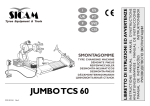
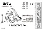
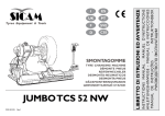
1
Tyr es Equipment & Tools yres F D SMONTAGOMME TYRE CHANGING MACHINE DÉMONTE PNEUS REIFENWECHSLER DESMONTA-NEUMATICOS ØÈÍÎÌÎÍÒÀÆÍÛÉ ÑÒÀÍÎÊ GRIFONE SL516 e versioni speciali and special versions - et versions spéciales - und Sonderausführungen y versiones especiales - È ÌÎÄÈÔÈÊÀÖÈÈ IT - S - ITS COD.102730 Rev.3 ES CSI INSTRUCTIONS MANUAL - MANUEL D’INSTRUCTIONS ANLEITUNGSHINWEISE - MANUAL DE INSTRUCCIONES ÐÓÊÎÂÎÄÑÒÂÎ ÏÎ ÝÊÑÏËÓÀÒÀÖÈÈ UK LIBRETTO DI ISTRUZIONI ED AVVERTENZE I ITALIANO ENGLISH FRANÇAIS AVVERTENZE WARNINGS AVERTISSEMENTS Il presente libretto di istruzioni costituisce parte integrante del prodotto. Leggere attentamente le avvertenze e le istruzioni in esso contenute in quanto forniscono importanti indicazioni riguardanti la sicurezza d’ uso e manutenzione. Conservare con cura questo libretto per ogni ulteriore consultazione. The present instructions booklet is an integral part of the product. Carefully study the warnings and instructions contained in it. This information is important for safe use and maintenance. Conserve this booklet carefully for further consultation. Ce manuel d’instructions fait partie intégrante du produit. Lire attentivement les avertissements et les instructions données car elles fournissent d’importantes indications concernant la sécurité d’emploi et d’entretien. Conserver avec soin pour toute consultation. GRIFONE SL516 IS AN AUTOMATIC TYRE CHANGING MACHINE DESIGNED AND CONSTRUCTED TO BE USED FOR THE MOUNTING AND DEMOUNTING OF TYRES FOR CARS AND MOTORCYCLES. GRIFONE SL516 EST UN DEMONTE PNEUS AUTOMATIQUE PROJETE ET CONSTRUIT POUR ETRE EMPLOYE EN TANT QU’EQUIPEMENT POUR LE DEMONTAGE ET LE MONTAGE DES PNEUS SUR LES JANTES DES ROUES DE VEHICULES ET MOTOCYCLETTES. THE MACHINE HAS BEEN DESIGNED TO OPERATE WITHIN THE LIMITS DESCRIBED IN THIS BOOKLET AND IN ACCORDANCE WITH THE MAKER’S INSTRUCTIONS. LA MACHINE A ÉTÉ PRÉVUE POUR FONCTIONNER DANS LES LIMITES INDIQUÉES DANS CE MANUEL ET SELON LES INSTRUCTIONS DU FABRICANT. The machine must be used only for the purpose for which it was expressly designed. Any other use is considered wrong and therefore unacceptable. The manufacturer cannot be held responsible for damage resulting from improper, erroneous, or unacceptable use of the machine. Elle ne devra être destinée qu’à l’emploi pour lequel elle a été conçue Tout autre emploi doit être considéré abusif et donc inadmissible. Le fabricant ne pourra être considéré responsable des éventuels dommages causés à la suite d’emplois abusifs, erronés et inadmissibles. This symbol is used in the present manual to warn the operator of particular risks associated with the use of the machine. Ce symbole est utilisé dans ce manuel pour attirer l’attention de l’opérateur sur des risques particuliers dérivant de l’utilisation de la machine. GRIFONE SL516 E’ UNO SMONTAGOMME AUTOMATICO PROGETTATO E COSTRUITO PER ESSERE UTILIZZATO QUALE ATTREZZATURA PER LO SMONTAGGIO ED IL MONTAGGIO DEI PNEUMATICI SU CERCHI DI RUOTE DI AUTOVEICOLI E MOTOCICLI. LA MACCHINA E’ STATA PREVISTA PER FUNZIONARE ENTRO I LIMITI INDICATI NEL PRESENTE LIBRETTO ED IN ACCORDO ALLE ISTRUZIONI DEL COSTRUTTORE. La macchina dovrà essere destinata solo all’uso per il quale è stata espressamente concepita. Ogni altro uso è da considerarsi improprio e quindi irragionevole. Il costruttore non può essere considerato responsabile per eventuali danni causati da usi impropri, erronei ed irragionevoli. Questo simbolo viene utilizzato nel presente manuale quando si vuole attirare l’attenzione dell’operatore su particolari rischi connessi con l’uso della macchina. INDICE CONTENTS INDEX AVVERTENZE ............................................................................................................................... 2 GENERAL WARNING .................................................................................................................... 2 AVERTISSEMENTS ...................................................................................................................... 2 CARATTERISTICHE TECNICHE ................................................................................................. 4 TECHNICAL CHARACTERISTICS .............................................................................................. 4 CARACTERISTIQUES TECHNIQUES ........................................................................................ 5 PARTI COMPONENTI ................................................................................................................... 6 COMPONENT PARTS .................................................................................................................. 6 COMPOSANTS ............................................................................................................................. 7 PARTI ACCESSORIE - Accessori in dotazione ............................................................................................................... 8 - Accessori a richiesta ................................................................................................................ 10 ACCESSORIES - Accessories provided .................................................................................................................. 8 - Accessories on request ............................................................................................................ 10 PARTIES ACCESSOIRES - accessoires en dotation .............................................................................................................. 9 - accessoires sur demande .......................................................................................................... 11 DISIMBALLO E COLLOCAMENTO ......................................................................................... 12 UNPACKING E LOCATION ......................................................................................................... 12 DEBALLAGE ET MISE EN PLACE ........................................................................................... 13 INSTALLAZIONE - Operazioni di assemblaggio ..................................................................................................... 14 - Collegamenti e prove di funzionamento .................................................................................. 16 - Malfunzionamenti, loro cause e possibili rimedi .................................................................... 18 INSTALLATION - Assembly procedures ................................................................................................................ 14 - Pneumatic and electrical connection ...................................................................................... 16 - Malfunctions: causes and possible remedies ......................................................................... 18 INSTALLATION - Opérations d’assemblage ......................................................................................................... 15 - Raccordements et essais de fonctionnement ......................................................................... 17 - Anomalies, leur causes et remédes possibles ....................................................................... 19 ISTRUZIONI PER L’USO - Operazioni di stallonamento e smontaggio del pneumatico .................................................. 20 - Operazioni di montaggio e gonfiaggio del pneumatico .......................................................... 22 INSTRUCTIONS FOR USE - Tyre bead breaking and unmounting operations ..................................................................... 20 - Mounting and inflation operations ............................................................................................ 22 INSTRUCTIONS D’UTILISATION - Opérations de détalonnement et de démontage du pneu ....................................................... 21 - Opérations de montage et de gonflage du pneu ..................................................................... 23 VERSIONI SPECIALI .................................................................................................................. 24 SPECIAL VERSIONS ................................................................................................................. 24 VERSIONS SPECIALES ............................................................................................................ 24 MANUTENZIONE ORDINARIA .................................................................................................. 34 ROUTINE MAINTENANCE ......................................................................................................... 34 ENTRETIEN COURANT ............................................................................................................. 35 MOVIMENTAZIONE E ACCANTONAMENTO .......................................................................... 34 MOVEMENT AND STORAGE ................................................................................................... 34 MANUTENTION ET MISE DE COTE ........................................................................................ 35 ASSISTENZA TECNICA E PARTI DI RICAMBIO ..................................................................... 36 TECHNICAL ASSISTANCE AND SPARE PARTS ..................................................................... 36 ASSISTANCE TECHNIQUE ET PIECES DETACHEES ........................................................... 36 COD. 102730 Rev.3 2 DEUTSCH ESPAÑOL ÐÓÑÑÊÈÉ HINWEISE ADVERTENCIAS ÐÅÊÎÌÅÍÄÀÖÈÈ Das vorliegende Anleitungsheft stellt einen Teil des Produkts dar. Lesen Sie aufmerksam die darin enthaltenen Hinweise und Anleitungen, da diese wichtige Angaben bezüglich der Sicherheit, der Anwendung und der Wartung enthalten. Dieses Heft für weiteres Nachschlagen sorgfältig aufbewahren. El presente manual de instrucciones forma parte integrante del producto. Leer atentamente las advertencias y las instrucciones que se señalan en el mismo, ya que suministran indicaciones importantes referentes a la seguridad del uso y mantenimiento. Conservar con cuidado este manual para ulteriores consultas. Íàñòîÿùàÿ èíñòðóêöèÿ ïî ýêñïëóàòàöèè ÿâëÿåòñÿ íåîòúåìëåìîé ÷àñòüþ ñòàíêà. Íåîáõîäèìî òùàòåëüíî èçó÷èòü ñîäåðæàùèåñÿ â íåé ðåêîìåíäàöèè è èíñòðóêöèè, òàê êàê îíè ïðåäîñòàâëÿþò âàæíóþ èíôîðìàöèþ, êàñàþùóþñÿ áåçîïàñíîñòè ýêñïëóàòàöèè è òåõîáñëóæèâàíèÿ. Äàííàÿ èíñòðóêöèÿ äîëæíà ñîõðàíÿòüñÿ äëÿ åå äàëüíåéøåãî èñïîëüçîâàíèÿ. GRIFONE SL516 IST EIN AUTOMATISCHER REIFENWECHSLER UND WURDE FÜR DEN EINSATZ BEIM REIFENABNEHMEN UND AUFZIEHEN AUF RADFELGEN VON PERSONENKRAFTWAGEN UND MOTORRÄDERN ENTWORFEN UND HERGESTELLT. GRIFONE SL516 ES UN DESMONTA-NEUMATICOS AUTOMATICO PROYECTADO Y CONSTRUIDO PARA SER UTILIZADO COMO HERRAMIENTA PARA EL DESMONTAJE Y EL MONTAJE DE LOS NEUMATICOS SOBRE LLANTAS DE RUEDAS DE TURISMOS Y DE MOTOCICLETAS. GRIFONE SL516 ÝÒÎ ÀÂÒÎÌÀÒÈ×ÅÑÊÈÉ ÄÅÌÎÍÒÀÆÍÛÉ ÑÒÀÍÎÊ ÄËß ØÈÍ, ÐÀÇÐÀÁÎÒÀÍÍÛÉ ÄËß ÏÐÈÌÅÍÅÍÈß Â ÊÀ×ÅÑÒÂÅ ÎÁÎÐÓÄÎÂÀÍÈß ÄËß ÄÅÌÎÍÒÀÆÀ È ÌÎÍÒÀÆÀ ØÈÍ ÍÀ ÊÎËÅÑÀÕ ËÅÃÊÎÂÛÕ ÌÀØÈÍ È ÌÎÒÎÖÈÊËÎÂ. LA MAQUINA HA SIDO IDEADA PARA FUNCIONAR DENTRO DE LOS LIMITES INDICADOS EN EL PRESENTE MANUAL DE USO Y EN CONFORMIDAD A LAS INSTRUCCIONES DEL CONSTRUCTOR. ÑÒÀÍÎÊ ÁÛË ÐÀÇÐÀÁÎÒÀÍ ÄËß ÝÊÑÏËÓÀÒÀÖÈÈ Â ÐÀÁÎ×ÈÕ ÓÑËÎÂÈßÕ, ÓÊÀÇÀÍÍÛÕ Â ÍÀÑÒÎßÙÅÌ ÐÓÊÎÂÎÄÑÒÂÅ, È Â ÑÎÎÒÂÅÒÑÒÂÈÈ Ñ ÓÊÀÇÀÍÈßÌÈ ÈÇÃÎÒÎÂÈÒÅËß. La máquina debe contemplar un uso adecuado únicamente a su ideación. Cualquier otro tipo de uso está considerado como impropio y por lo tanto irrazonable. No se ha de considerar responsable al constructor si la máquina sufrirá daños causados por un uso inadecuado y erróneo. Ñòàíîê äîëæåí ïðèìåíÿòüñÿ äëÿ âûïîëíåíèÿ òîëüêî òåõ îïåðàöèé, äëÿ êîòîðûõ îí áûë ñïåöèàëüíî ðàçðàáîòàí. Ëþáîå äðóãîå åãî ïðèìåíåíèå äîëæíî ñ÷èòàòüñÿ íåïðàâèëüíûì è íå ïî íàçíà÷åíèþ. Èçãîòîâèòåëü íå ìîæåò áûòü ïðèâëå÷åí ê îòâåòñòâåííîñòè çà ïîâðåæäåíèÿ, âûòåêàþùèå èç íåïðàâèëüíîãî èëè îøèáî÷íîãî ïðèìåíåíèÿ, è èñïîëüçîâàíèÿ íå ïî íàçíà÷åíèþ. DIE MASCHINE WURDE FÜR DEN BETRIEB INNERHALB DER IM VORLIEGENDEN HEFT ANGEGEBENEN GRENZEN UND IN ÜBEREINSTIMMUNG MIT DEN HERSTELLERANGABEN VORGESEHEN.. Die Maschine ist nur für den Gebrauch bestimmt, für den sie ausdrücklich geschaffen wurde. Jede andere Anwendung ist als zweckentfremdet und somit unsinnig anzusehen. Der Hersteller kann nicht als haftend gelten, für eventuelle Schäden, die durch uneigenen, falschen und unsinnigen Gebrauch bedingt sind.. Dieses Symbol wird im vorliegenden Handbuch verwendet, wenn die Aufmerksamkeit des Bedieners auf besondere Risiken im Zusammenhang mit dem Gebrauch der Maschine gelenkt werden soll. INHALT Este símbolo se utiliza en el presente manual cuando se desea llamar la atención del operador sobre particulares riesgos relacionados con el uso de la máquina. ÍNDICE Ýòîò ñèìâîë èñïîëüçóåòñÿ â íàñòîÿùåì ðóêîâîäñòâå â òîì ñëó÷àå, êîãäà õîòÿò îáðàòèòü âíèìàíèå îáñëóæèâàþùåãî ïåðñîíàëà íà îñîáûå ðèñêè ñâÿçàííûå ñ ýêñïëóàòàöèåé ñòàíêà. ÑÎÄÅÐÆÀÍÈÅ HINWEISE ...................................................................................................................................... 3 ADVERTENCIAS GENERALES ................................................................................................... 3 ÏÐÅÄÓÏÐÅÆÄÅÍÈß ........................................................................................................................... 3 TECHNISCHE MERKMALE .......................................................................................................... 5 CARACTERISTICAS TECNICAS ................................................................................................. 5 ÒÅÕÍÈ×ÅÑÊÈÅ ÕÀÐÀÊÒÅÐÈÑÒÈÊÈ .............................................................................................. 5 EINZELTEILE ................................................................................................................................ 7 DESCRIPCION DE LA MAQUINA ................................................................................................ 7 ÎÏÈÑÀÍÈÅ ÑÒÀÍÊÀ ............................................................................................................................ 7 ZUBEHÖR - Standardzubehör .......................................................................................................................... 9 - Zusätzliches Zubehör auf Wunsch .......................................................................................... 11 DESCRIPCION DE LAS PIEZAS COMPONENTES - Accesorios de equipo .................................................................................................................. 9 - Accesorios opcionales .............................................................................................................. 11 ÏÐÈÍÀÄËÅÆÍÎÑÒÈ - âõîäÿùèå â êîìïëåêò ..................................................................................................................... 9 - ïîñòàâëÿåìûå ïî çàïðîñó .......................................................................................................... 1 1 AUSPACKEN UND AUFSTELLEN ............................................................................................ 13 DESEMBALAJE Y COLOCACION ............................................................................................ 13 ÐÀÑÏÀÊÎÂÊÀ È ÐÀÇÌÅÙÅÍÈÅ INSTALLATION . - Montagearbeiten ........................................................................................................................ 15 - Anschlüsse und Funktionsproben ........................................................................................... 17 - Funktionsstörungen, Ursachen u. Abhilfemöglichkeiten Bedienungsanleitung ................... 19 INSTALACION - Operaciones de montaje ........................................................................................................... 15 - Conexión neumatica y eléctrica .............................................................................................. 17 - Mal funcionamiento, su causa y posible remedio .................................................................. 19 ÓÑÒÀÍÎÂÊÀ - Îïåðàöèè ïî ñáîðêå è óñòàíîâêå ............................................................................................ 15 - Ïîäñîåäèíåíèå è ïðîâåðêà ðàáîòû ....................................................................................... 17 - Íåèñïðàâíîñòè, èõ ïðè÷èíû è âîçìîæíûå ñïîñîáû óñòðàíåíèÿ ................................. 19 BEDIENUNGSANLEITUNG - Abdrücken und Abmontieren des Reifens ............................................................................... 21 - Montage und Aufpumpen des Reifens ..................................................................................... 23 INSTRUCCIONES PARA EL USO - Operaciones de destalonamiento y desmontaje del neumático ............................................ 21 - Operaciones de montaje y de hinchamiento del neumático .................................................. 23 ÏÐÀÂÈËÀ ÝÊÑÏËÓÀÒÀÖÈÈ - Îïåðàöèè ïî ðàçáîðòîâêå è äåìîíòàæó øèí .................................................................... 21 - Îïåðàöèè ïî ìîíòàæó è íàêà÷èâàíèþ øèí .......................................................................... 23 SONDERAUSFÜHRUNGEN ........................................................................................................ 25 VERSIONES ESPECIALES ....................................................................................................... 25 ÑÏÅÖÈÔÈÊÀÖÈß ÌÎÄÈÔÈÊÀÖÈÉ ............................................................................................ 25 STANDARDWARTUNG ............................................................................................................... 35 MANTENIMIENTO RUTINARIO ................................................................................................. 35 ÏËÀÍÎÂÎÅ ÒÅÕÍÈ×ÅÑÊÎÅ ÎÁÑËÓÆÈÂÀÍÈÅ ....................................................................... 35 STANDORTWECHSEL UND STILLEGUNG ............................................................................. 35 INSTRUCCIONES PARA MOVER Y ARRINCONAMIENTO ................................................... 35 ÏÅÐÅÌÅÙÅÍÈÅ, ÕÐÀÍÅÍÈÅ È ÓÒÈËÈÇÀÖÈß ....................................................................... 35 TECHNISCHE WARTUNG UND ERSATZTEILE ...................................................................... 37 ASISTENCIA TECNICA Y PIEZAS DE REPUESTO ............................................................... 37 ÒÅÕÍÈ×ÅÑÊÎÅ ÎÁÑËÓÆÈÂÀÍÈÅ È ÇÀÏÀÑÍÛÅ ×ÀÑÒÈ .................................................... 37 COD. 102730 Rev.3 3 ITALIANO ENGLISH CARATTERISTICHE TECNICHE TECHNICAL CHARACTERISTICS DATI TECNICI TECHNICAL DATA GRIFONE SL516 DIMENSIONI Altezza Max ......................................................................... 1830 mm. Profondità .............................................................................. 950 mm. Larghezza ............................................................................... 760 mm. DIMENSIONS Max. height .......................................................................... 1830 mm. Depth ..................................................................................... 950 mm. Width ...................................................................................... 760 mm. PESO Peso Netto ................................................................................. 198 kg Peso Lordo ................................................................................ 226 kg WEIGHT Net weight ................................................................................. 198 kg Gross weight ............................................................................. 226 kg MOTORE ELETTRICO (2 velocità) Potenza .................................................................................... 0.75 Hp Fasi ................................................................................................... 3 ~ Alimentazione ...................................................................... 230-400V Forza Stallonatore ................................................................. 2.500 kg ELECTRIC MOTOR Power ....................................................................................... 0.75 Hp Phases ............................................................................................. 3 ~ Voltage ................................................................................. 230-400V Bead breaker force ................................................................. 2.500 kg RUMOROSITA’ ........................................................................... 75 db NOISE LEVEL ............................................................................ 75 db ALIMENTAZIONE PNEUMATICA Pressione d’es. min / max ........................... 800-1200 kPa (8-12 bar) PNEUMATIC SUPPLY Min./max. operating pressure ...................... 800-1200 kPa (8-12 bar) GAMMA DI APPLICAZIONI RANGE OF APPLICATIONS GRIFONE SL516 può operare su ruote e cerchi aventi le seguenti dimensioni minime e massime: GRIFONE SL516 can operate on wheels having the following minimum and maximum dimensions: RUOTE AUTOVETTURA min/max Larghezza ruota ......................................................................... 3"-12" Diametro max ruota .............................................................. 1000 mm Diametro cerchio.(bloccaggio interno ................................... 12"-22" Diametro cerchio (bloccaggio.esterno .................................... 10"-20" VEHICLE WHEEL min/max Wheel width ............................................................................... 3"-12" Max. wheel diameter ............................................................ 1000 mm Rim diameter (locked internally .............................................. 12"-22" Rim diameter (locked externally ............................................ 10"-20" RUOTE MOTOCICLO * min/max Larghezza Ruota ....................................................................... 3"-10" Diametro max. ruota ............................................................. 1000 mm Diametro cerchio .................................................................... 15"-”25" MOTORCYCLE WHEEL * min/max Wheel width ............................................................................... 3"-10" Max. wheel diameter ............................................................ 1000 mm Rim diameter ......................................................................... 15"-”25"* * Per operare su ruote motociclo è necessario installare il dispositivo attacchi moto, disponibile su richiesta (v.pag.10) In order to work on motorcycle wheels it is necessary to install the motorcycle attachments, available on request (see pg.10). DATI DI TARGA REGISTRATION PLATE DATA I DATI DELLA MACCHINA SONO CONTENUTI IN APPOSITA ETICHETTA INDELEBILE POSTA SUL RETRO DELLA MACCHINA STESSA. THE MACHINE DATA IS ON A SPECIAL INDELIBLE LABEL ON THE BACK OF THE MACHINE. In essa vengono riportati i dati tecnici, la marcatura CE, l’anno di costruzione ed il numero di matricola. This contains the specifications, the CE mark, the year of construction and the serial number. Il Numero di matricola deve essere citato nelle comunicazioni con l’assistenza tecnica. The Serial number must be quoted in the communications with technical assistance. COD. 102730 Rev.3 DATI DI TARGA REGISTRATION PLATE DATA DONNEES DE PLAQUE ANGABEN AUF DEM MATRIKELSCHILD DATOS DE CHAPA ÄÀÍÍÛÅ ÒÀÁËÈ÷ÊÈ 4 FRANÇAIS DEUTSCH ESPAÑOL ÐÓÑÑÊÈÉ CARACTERISTIQUES TECHNIQUES TECHNISCHE MERKMALE CARACTERISTICAS TECNICAS ÒÅÕÍÈ÷ÅÑÊÈÅ ÄÀÍÍÛÅ DONNÉES TECHNIQUES TECHNISCHE DATEN DATOS TECNICOS ÒÅÕÍÈ÷ÅÑÊÈÅ ÄÀÍÍÛÅ DIMENSIONS Hauteur maxi ........................................................................ 1830 mm. Profondeur ............................................................................. 950 mm. Largeur .................................................................................... 760 mm. MAßE Maximale Höhe ................................................................... 1830 mm. Tiefe ...................................................................................... 950 mm. Breite ...................................................................................... 760 mm. DIMENSIONES Altura máx ............................................................................ 1830 mm. Profundidad ........................................................................... 950 mm. Anchura .................................................................................. 760 mm. ÐÀÇÌÅÐÛ Ìàêñ. âûñîòà .......................................................................... 1830 ìì. Øèðèíà ....................................................................................... 950 ìì. Ìàêñ. äëèíà ................................................................................ 760 ìì. POIDS Poids net ................................................................................... 198 kg Poids brut .................................................................................. 226 kg GEWICHT Nettogewicht ............................................................................. 198 kg Bruttogewicht ............................................................................ 226 kg PESO Peso Neto .................................................................................. 198 kg Peso Bruto ................................................................................. 226 kg ÂÅÑ Âåñ íåòòî ........................................................................................ 198 êã Âåñ áðóòòî ..................................................................................... 226 êã MOTEUR ELECTRIQUE Puissance ................................................................................ 0.75 Hp Phases ............................................................................................. 3 ~ Alimentation ......................................................................... 230-400V Force détalonneur .................................................................. 2.500 kg ELEKTROMOTOR Leistung .................................................................................... 0.75 Hp Phasen ............................................................................................. 3 ~ Spannung ............................................................................. 230-400V Abdrückvermögen .................................................................. 2.500 kg MOTOR ELECTRICO (2vel) Potencia ................................................................................... 0.75 Hp Fases ............................................................................................... 3 ~ Alimentación ........................................................................ 230-400V Fuerza Destalonador ............................................................. 2.500 kg ÝËÅÊÒÐÎÄÂÈÃÀÒÅËÜ (2 ñêîðîñòè) Ì î ù í î ñ ò ü .................................................................................... 0.75 ëñ Ôàçû .................................................................................................... 3 ~ Ïèòàíèå .................................................................................... 230-400 Óñèëèå ðàçáîðòîâî÷íîãî óñòðîéñòâà ........................... 2.500 êã NIVEAU DE BRUIT ..................................................................... 75 db GERÄUSCHERZEUGUNG .......................................................... 75 db RUIDOSIDAD .............................................................................. 75 db ÓÐÎÂÅÍÜ ØÓÌÀ .......................................................................... 75 äÁ ALIMENTATION PNEUMATIQUE Pression de service mini/maxi .................... 800-1200 kPa (8-12 bar) LUFTZUFUHR Geringster/größter Betriebsdruck mind/max 800-1200 kPa (8-12 bar) ALIMENTACION NEUMATICA Presión de trabajo mín/máx ......................... 800-1200 kPa (8-12 bar) ÏÈÒÀÍÈÅ ÑÆÀÒÛÌ ÂÎÇÄÓÕÎÌ Ðàáî÷åå äàâëëåíèå ìèí/ìàêñ ............. 800-1200 êÏà (8-12 áàð) CHAMPS D’APPLICATION ANWENDUNGSBEREICH GAMA DE APLICACIONES ÎÁËÀÑÒÜ ÏÐÈÌÅÍÅÍÈß GRIFONE SL516 peut agir sur roues et jantes ayant les suivantes dimensions mini et maxi GRIFONE SL516 kann bei Rädern und Reifenfelgen mit den folgenden Mindest- und Höchstmaßen eingesetzt werden: GRIFONE SL516 puede obrar sobre ruedas y llantas con las dimensiones mínimas y máximas siguientes.: GRIFONE SL516 ïðåäíàçíà÷åí äëÿ ðàáîòû ñ êîëåñàìè è äèñêàìè ñî ñëåäóþùèìè ìèíèìàëüíûìè è ìàêñèìàëüíûìè ðàçìåðàìè: ROUES mini/maxi Largeur roue ................................................................................ 3"-12" Diamètre maxi roue .............................................................. 1000 mm Diamètre jante (bl. int.) ........................................................... 12"-22" Diamètre jante (bl. ext.) .......................................................... 10"-20" REIFEN PERSONENKRAFTWAGEN mind/max Reifenbreite ................................................................................ 3"-12" Raddurchmesser ................................................................... 1000 mm Felgendurchmesser (Innenblockierung ................................. 12"-22" Felgendurchmesser (Außenblockierung ............................... 10"-20" RUEDAS AUTOMOVILES mín/máx Anchura rueda ........................................................................... 3"-12" Diámetro máx. rueda ............................................................ 1000 mm Diámetro llanta (bloqueo int .................................................... 12"-22" Diámetro llanta (bloqueo ext ................................................... 10"-20" ÊÎËÅÑÀ ËÅÃÊÎÂÛÕ ÀÂÒÎÌÎÁÈËÅÉ ìèí/ìàêñ. Øèðèíà êîëåñà .............................................................................. 3"-12" Ìàêñ. äèàìåòð êîëåñà .......................................................... 1000 ìì Äèàìåòð äèñêà (âíóòðåííÿÿ áëîêèðîâêà) ....................... 12"-22" Äèàìåòð äèñêà (âíåøíÿÿ áëîêèðîâêà) ............................. 10"-20" ROUES MOTOCYCLETTE* mini/maxi Largeur roue ................................................................................ 3"-10" Diamètre maxi roue .............................................................. 1000 mm Diamètre jante .......................................................................... 15"-25" MOTORRADRÄDER* mind/max Reifenbreite ................................................................................ 3"-10" Raddurchmesser ................................................................... 1000 mm Felgendurchmesser ............................................................... 15"-”25" RUEDAS MOTOCICLETAS mín/máx Anchura rueda ............................................................................ 3"-10" Diámetro máx. rueda ............................................................ 1000 mm Diámetro llanta ....................................................................... 15"-”25" ÌÎÒÎÖÈÊËÅÒÍÛÅ ÊÎËÅÑÀ * ìèí/ìàêñ. Øèðèíà êîëåñà .............................................................................. 3"-10" Ìàêñ. äèàìåòð êîëåñà .......................................................... 1000 ìì Äèàìåòð äèñêà ............................................................................ 15"-25" * Pour opérer sur les roues de moto il faut installer le dispositif de fixation moto, disponible sur demande (voir page 11). * Um das Gerät bei Motorrädern einsetzen zu können, ist der Einbau der entsprechenden Vorrichtung für den Anschluß an Motorräder notwendig, die Ihnen auf Wunsch geliefert wird (siehe Seite 11). * Para obrar sobre ruedas de motocicletas es necesario instalar el dispositivo “conexión motocicletas”, disponible a pedido (v.pág.11) Äëÿ ðàáîòû ñ ìîòîöèêëåòíûìè êîëåñàìè íåîáõîäèìî óñòàíîâèòü óñòðîéñòâî ñ ìîòîöèêëåòíûìè êðåïëåíèÿìè, ïîñòàâëÿþùèìèñÿ ïî îòäåëüíîìó çàêàçó (ñì. ñòð. 11). DONNEES DE PLAQUE ANGABEN AUF DEM MATRIKELSCHILD DATOS DE CHAPA ÄÀÍÍÛÅ ÒÀÁËÈ×ÊÈ LES DONNEES DE LA MACHINE SONT INDIQUEES SUR UNE ETIQUETTE SPECIALE INDELEBILE PLACEE SUR L’ARRIERE DE LA MACHINE. DIE MASCHINENDATEN BEFINDEN SICH AUF DEM PERMANENTEN ETIKETT AUF DER RÜCKSEITE DER MASCHINE. LOS DATOS DE LA MÁQUINA SE ENCUENTRAN EN LA ETIQUETA INDELEBLE SITUADA EN LA PARTE TRASERA DE LA MÁQUINA. ÄÀÍÍÛÅ ÑÒÀÍÊÀ ÓÊÀÇÀÍÛ ÍÀ ÑÏÅÖÈÀËÜÍÎÉ ÍÅÑÌÛÂÀÅÌÎÉ ÝÒÈÊÅÒÊÅ ÐÀÑÏÎËÎÆÅÍÍÎÉ ÍÀ ÇÀÄÍÅÉ ÑÒÎÐÎÍÅ ÑÀÌÎÃÎ ÑÒÀÍÊÀ. Es enthält die technischen Daten, die CE-Markierung, das Baujahr und die Matrikelnummer. En la misma se señalan los datos técnicos, la marca CE, el año de construcción y el número de matrícula. Die Matrikelnummer ist bei der Korrespondenz mit dem Kundendienst zu nennen. El Número de matrícula debe ser citado en las comunicaciones con la asistencia técnica Les données techniques, le marquage CE, l’année de fabrication et le numéro de série sont reportés sur cette étiquette. Le numéro de série doit être mentionné sur toutes les communications au service après-vente. COD. 102730 Rev.3  íåé óêàçàíû òåõíè÷åñêèå äàííûå, ìàðêèðîâêà ÅÑ, ãîä èçãîòîâëåíèÿ è çàâîäñêîé íîìåð.  çàïðîñàõ íà òåõíè÷åñêîå îáñëóæèâàíèå íåîáõîäèìî âñåãäà óêàçûâàòü çàâîäñêîé íîìåð. 5 ITALIANO ENGLISH GRIFONE SL516 DESCRIZIONE DELLA MACCHINA DESCRIPTION OF THE MACHINE con illustrazione delle parti componenti rilevanti ai fini dell’uso with illustrations of the component parts relevant for use PEDALIERA (fig.1) (1) Comprende i pedali di comando della macchina: » Il pedale comando invertitore (1-A), presente su entrambe i lati della macchina, per far ruotare il piatto autocentrante nel senso desiderato; » Il pedale comando stallonatore (1-B) per azionare il braccio stallonatore (2-F) » Il pedale comando apertura (1-C) per aprire le griffe dell’autocentrante (4-P) » Il pedale comando chiusura (1-D) per chiudere le griffe dell’autocentrante (4-P). PEDAL CONTROLS (fig. 1)(1) The machine control pedals include: » Invertor control pedal (1-A) is on both sides of the machine and rotates the chuck plate in the direction desired; » Bead breaking control pedal (1-B) to activate the bead breaking arm (2-F) » Open control pedal (1-C) for opening and closing the chuck jaws (4P) » Close control pedal (1-D) for closing the chuck jaws (4-P) STALLONATORE (fig.1) (2) Lo Stallonatore è il dispositivo per stallonare il pneumatico dal cerchio e si compone di: » Braccio Stallonatore (2-F) azionato pneumaticamente da un cilindro a doppio effetto; » Paletta (2-E) per lo stallonamento del pneumatico; » Appoggi antiabrasivi (2-G) per l’appoggio del cerchio durante la fase di stallonamento. GRUPPO PALO (Fig.1) (3) Il Gruppo Palo è composto da un Palo fisso che supporta i componenti necessari per smontare il pneumatico dal cerchio (e per rimontarlo): » Il Braccio mobile a bandiera (3-H) per il posizionamento della Torretta. » Il Volantino (3M) per la regolazione della posizione orizzontale del braccio. » La Leva di bloccaggio (3-L) per la regolazione della posizione verticale dell’asta » La Torretta (3-I) per togliere (e rimontare) il pneumatico dal cerchio con l’ausilio della leva alzatalloni (vedere accessori in dotazione). » Il Rullino di scorrimento (3-N), inserito nella linguetta della torretta, permette di operare sui pneumatici senza rovinare cerchio e tallone. AUTOCENTRANTE (Fig.1) (4) L’autocentrante è il dispositivo per il bloccaggio e la rotazione del cerchio; è azionato pneumaticamente da 2 cilindri “autocentranti ed è composto da: » 4 corsie mobili (4-P) con cunei di bloccaggio (4-O) per il bloccaggio interno od esterno del cerchio; » un piatto autocentrante (4-Q) per ruotare il cerchio nei due sensi senza sbloccarlo. LEGENDA 1 BEAD BREAKER (fig. 1) (2) The bead breaker is a mechanism for unbeading tyres from rims and is composed of: » Bead breaking arm (2-F) activated pneumatically by a double action cylinder » Plate (2-E) for tyre bead breaking » Anti-abrasion supports (2-G) for support during the bead breaking phase. COLUMN UNIT (Fig.1) (3) The column unit is composed of a fixed column which can be tilted back and which carries the components necessary for unmoun-ting the tyre from the rim (and for re-mounting) » the swinging arm (3-H) for positioning the head. » the handwheel (3M) for the adjustment of the horizontal position of the arm: » locking lever (3-L) for regulating the vertical position of the rod » the head (3-I) for removing (and refitting) the tyre from the rim with the help of the bead lifting lever (see accessories provided). » the sliding roller (3-N), inserted inside the tongue of the head, avoids any damage to the rim or bead. SELF-CENTERING CHUCK (Fig.1) (4) The chuck is the device for locking and rotating the rim. It is driven pneumatically two self-centring cylinders and is composed of: » 4 slide tracks (4-P) with 4 locking wedges (4-O) for the internal and external locking of the rim » A self-centring plate (4-Q) for rotating the rim in both directions without unlocking it. KEY 1) PEDALIERA A: Pedale Invertitore B: Pedale Stallonatore C: Pedale Apertura D: Pedale Chiusura 3) PALO H: Braccio a Bandiera I: Torretta L: Leva di Bloccaggio verticale N: Rullino di scorrimento 1) PEDALS A: Invertor pedal B: Bead-breaker pedal C: Open pedal D: Close pedal 3) COLUMN H: Swinging arm I: Head L: Locking lever N: Sliding roller 2) STALLONATORE E: Paletta Stallonatore F: Braccio Stallonatore G: Appoggi antiabrasivi 4) AUTOCENTRANTE O: Cunei di bloccaggio P: Corsie mobili Q: Piatto Autocentrante 2) BEAD-BREAKER E: Bead-breaking plate F: Bead-breaking arm G: Anti-abrasion supports 4) SELF-C.CHUCK O: Locking wedges P: Slide tracks Q: Self-centring plates COD. 102730 Rev.3 6 FRANÇAIS DEUTSCH ESPAÑOL ÐÓÑÑÊÈÉ DESCRIPTION DE L’APPAREIL GERÄTEBESCHREIBUNG DESCRIPCION DE LA MAQUINA ÎÏÈÑÀÍÈÅ ÑÒÀÍÊÀ avec illustration des parties composantes relatives à l’emploi mit Zeichenerklärung der Einzelteile con ilustraciones de las piezas componentes importantes para el uso ñ èëëþñòðàöèåé ñîñòàâëÿþùèõ ÷àñòåé, èìåþùèõ âàæíîå çíà÷åíèå äëÿ ðàáîòû ñòàíêà PEDALIER (fig.1) ( 1) Ice sont les pédales de commande de la machine: » la pédale de commande de l’inverseur (1-A), présente sur les deux côtés de la machine, afin de faire tourner le plateau autocentreur dans le sens souhaité; » La pédale de commande du détalonneur (1-B) pour actionner le bras détalonneur (2-F) » La pédale de commande de l’ouverture (1-C) pour ouvrir les griffes de l’autocentreur (4-P) » La pédale de commande de fermeture (1-D) pour fermer les griffes de l’autocentreur (4-P). FUßSCHALTUNG (Abb. 1) (1) Enthält die Kommandopedale des Geräts: » Umkehrpedal (1-A) zur Drehung der Selbstzentriererplatte in der gewünschten Richtung; » Abdrückpedal (1-B) zur Ingangsetzung der Abdrückkralle (2-F); » Öffnungspedal (1-C) zum Öffnen der Greifer des Selbstzentrierers (4-P); » Schließpedal (1-D) zum Schließen der Greifer des Selbstzentrierers (4-P); JUEGO DE PEDALES (fig.1) (1) Incluye los pedales de mando de la máquina: » Pedal mando invertidor (1-A) presente en los dos lados de la máquina, para hacer girar el plato autocentrado en el sentido deseado. » Pedal mando destalonador (1-B) para accionar el brazo destalonador (2-F). » Pedal mando abertura (1-C) para abrir y cerrar las mordazas del Autocentrado (4-P) » Pedal mando cierre (1-D) para cerrar las mordazas del Autocentrado (4-P). ÏÅÄÀËÈ (ðèñ.1) (1) Ïåäàëè óïðàâëåíèÿ ñòàíêà: » Ïåäàëü óïðàâëåíèÿ èíâåðòîðîì íàïðàâëåíèÿ âðàùåíèÿ (1-A), íàõîäèòñÿ íà îáåèõ ñòîðîíàõ ñòàíêà, ñëóæèò äëÿ âðàùåíèÿ ñàìîöåíòðèðóþùåãîñÿ ñòîëà â íåîáõîäèìîì íàïðàâëåíèè; » Ïåäàëü ðàçáîðòîâêè ïîêðûøêè (1-B) äëÿ ïðèâåäåíèÿ â äåéñòâèå ðû÷àãà ðàçáîðòîâêè ïîêðûøêè (2-F) » Ïåäàëü óïðàâëåíèÿ îòêðûòèÿ (1-C) äëÿ îòêðûòèÿ çàæèìîâ ñàìîöåíòðèðóþùåãîñÿ ñòîëà (4-P) » Ïåäàëü óïðàâëåíèÿ çàêðûòèÿ (1-D) äëÿ çàêðûòèÿ çàæèìîâ ñàìîöåíòðèðóþùåãîñÿ ñòîëà (4-P). DÉTALONNEUR (fig.1-2) Le détalonneur est le dispositif pour détalonner le pneu de la jante et il est formé: » du bras détalonneur (2-F) actionné pneumatiquement par un vérin à double effet; » d’un outil (2-E) pour le détalonnement du pneu; » d’appuis antiabrasifs (2-G) pour l’appui de la jante pendant la phase de détalonnement. GROUPE DE LA POTENCE (Fig.1) (3) Le Groupe de la Potence est formé d’une Potence fixe qui soutient les composants nécessaires à démonter le pneu de la jante (aussi bien que pour le monter à nouveau): » le Bras mobile en drapeau (3-H) pour le positionnement de la Tourelle. » le Petit Volant (3M) pour le réglage de la position horizontale du bras. » le Levier de blocage (3-L) pour le réglage de la position verticale de la tige » la Tourelle (3-I) pour sortir et remonter le pneu de la jante à l’aide du levier lève-talons (voir accessoires en dotation). Le petit Rouleau de glissement (3-N), dans la languette de la tourelle, permet de travailler sur les pneus sans abîmer la jante et le talon. AUTOCENTREUR (fig.1) (4) L’autocentreur est le dispositif pour le blocage et la rotation de la jante; il est actionné pneumatiquement par 2 vérins “autocentreurs” et il est formé: » de 4 voies mobiles (4-P) avec coins de blocage (4-O) pour le blocage intérieur ou extérieur de la jante; » d’un plateau autocentreur (4-Q) pour faire tourner la jante dans les deux sens sans la débloquer. ABDRÜCKER (Abb.1) (2) Vorrichtung für das Abdrücken des Reifens vom Reifenfelgen, besteht aus: » Abdrückkralle (2-F), wird von einem Doppelzylinder pneumatisch in Gang gesetzt; » Schaufel (2-E) für das Abdrücken des Reifens; » Kratzsichere Halterungen (2-G) zum Anlehnen des Reifenfelgens während des Abdrückvorgangs TRAGSÄULENGRUPPE (Abb.1) (3) besteht aus einem kippbaren Mast, der die für das Abmontieren des Reifens vom Felgen (und für die Neumontage) notwendigen Einzelteile trägt. » Schwenkbarer Laufarm (3-H) für die Positionierung des Drehkopfs; » Handrad (3-M) für die Horizontaleinstel-lung des Laufarms; » Sperrhebel (3-L) für die Regulierung der Senkrechtstellung des Stabs; » Drehkopf (3-I) für die Ab- und Aufmontage des Reifens vom und auf den Reifenfelgen mit Hilfe des Wulstheberhebels (siehe Grundausrüstung). Die Gleitrolle (3-N), im Drehkopfkeil eingebaut, ermöglicht die Arbeit am Reifen ohne Beschädigung des Rad-felgens und des Wulstes. SELBSTZENTRIERER (Abb.1) (4) Vorrichtung für die Blockierung und Drehung des Reifenfelgens; sie wird von zwei selbstzentrierenden Zylindern pneumatisch in Gang gesetzt und besteht aus » 4 beweglichen Schienen (4-P) mit Blockierungsrillen (4-O) für die Innen- und Außenblockierung des Reifenfelgens; » Selbstzentriererplatte (4-Q) zur Drehung des Felgens in beide Richtungen, ohne ihn zu entblocken.. ZEICHENERKLÄRUNG LEGENDE DESTALONADOR (fig.1) (2) El Destalonador es el dispositivo para destalonar el neumático de la llanta e incluye: » Brazo Destalonador (2-F) accionado neumá-ticamente por un cilindro de doble efecto. » Paleta (2-E) para el destalonamiento del neumático. » Apoyos antiabrasivos (2-G) para apoyar la llanta durante la fase de destalonamiento. UNIDAD COLUMNA (fig.1) (3) La Unidad Columna se compone de una Columna fija que soporta los componentes necesarios para desmontar el neumático de la llanta (y para montarlo nuevamente): » el brazo oscilante (3-H) para la colocación de la Torre; » la manivela (3M) para el arreglo de la posición horizontal del brazo; » la palanca de bloqueo (3-L) para ajustar la posición vertical de la barra. » la torre (3- I) para quitar el neumático de la llanta (y para montarlo nueva-mente) con el auxilio de la palanca levanta-talones (vea accesorios de equipo); » el rodillo de deslizamiento (3-N) insertado en la lengüeta de la Torre, permite actuar sobre el neumático sin dañar llanta y talón. AUTOCENTRADO (fig.1) (4) El Autocentrado es el dispositivo para el bloqueo y la rotación de la llanta; se acciona neumáticamente gracias a dos cilindros autocentrados y se compone de: » 4 recorridos móviles (4-P) con cuñas de bloqueo (4-O) para el bloqueo interior y exterior de la llanta. » un plato autocentrado (4-Q) para girar la llanta en los dos sentidos sin desbloquearla.. EXPLICACION 1) ENSEMBLE DES PEDALES A: Pédale inverseur B: Pédale détalonneur C: Pédalie ouverture D: Pédale fermeture 3) POTENCE H: Bras en drapeau I: Tourelle L: Levier de Blocage vertical N: Rouleau de coulissement 1) FUßSCHALTUNG A: Umkehrpedal B: Abdrückpedal C: Öffnungspedal D: Schließpedal 3) TRAGSÄULE H: Schwenkbarer Gleitarm I: Drehkopf L: Sperrhebel senkrecht N: Gleitrolle 1) JUEGO DE PEDALES A: Pedal Invertidor B: Pedal Destalonador C: Pedal Abertura D: Pedal Cierre 3) COLUMNA H: Brazo oscilante I: Torre L : Palanca de Bloqueo N: Rodillo de deslizamiento 2) DETALONNEUR E: Outil Détalonneur F: Bras détalonneur G: Appuis antiabrasifs 4) AUTOCENTREUR O: Coins de blocage P: Voies mobiles Q: Plateau autocentreur 2) ABDRÜCKER E: Abdrückklaue F: Abdrückkralle G: Kratzsichere Halterungen 4) SELBSTZENTRIERER O: Blockierrillen P: Bewegliche Schienen Q: Selbstzentriererplatte 2) DESTALONADOR E: Paleta Destalonador F: Brazo Destalonador G: Apoyos antiabrasivos 4) AUTOCENTRADO O: Cuñas de Bloqueo P: Recorridos móviles Q: Plato Autocentrado COD. 102730 Rev.3 ÐÀÇÁÎÐÒÎÂÎ×ÍÎÅ ÓÑÒÐÎÉÑÒÂÎ (ðèñ.1) (2) Ðàçáîðòîâî÷íîå óñòðîéñòâî - ýòî ïðèñïîñîáëåíèå äëÿ ðàçáîðòîâêè ïîêðûøêè ñ äèñêà, êîòîðîå ñîñòîèò èç: » ðàçáîðòîâî÷íîãî ðû÷àãà (2-F), ïðèâîäèìîãî â äâèæåíèå öèëèíäðîì ñ äâîéíûì ýôôåêòîì; » ëîïàòêè (2-E) äëÿ ðàçáîðòîâêè øèíû; » àíòèàáðàçèâíûõ îïîð (2-G) äëÿ óñòàíîâêè íà íèõ äèñêà âî âðåìÿ ðàçáîðòîâêè. ÁËÎÊ ÑÒÎÉÊÈ (ðèñ.1) (3) Áëîê ñòîéêè ñîñòîèò èç ôèêñèðîâàííîé ñòîéêè, íà êîòîðóþ êðåïÿòñÿ äåòàëè, íåîáõîäèìûå äëÿ äåìîíòàæà ïîêðûøêè ñ äèñêà (è ìîíòàæà), òàêèå êàê: » Ïîäâèæíûé îòêèäíîé ðû÷àã (3-H) äëÿ óñòàíîâêè ðàáî÷åé ñòîéêè; » Ìàõîâè÷îê (3M) äëÿ ðåãóëèðîâêè ãîðèçîíòàëüíîãî ïîëîæåíèÿ ðû÷àãà; » Ðóêîÿòêà áëîêèðîâêè (3-L) äëÿ ðåãóëèðîâêè âåðòèêàëüíîãî ïîëîæåíèÿ øòàíãè; » Ãîëîâêà ðàáî÷åé ñòîéêè (3-I) äëÿ ñíÿòèÿ (è óñòàíîâêè) ïîêðûøêè ñ äèñêà ïðè ïîìîùè ðû÷àãà-îòäåëèòåëÿ (ñì. ïðèíàäëåæíîñòè). Õîäîâîé âàëèê (3-N), âñòàâëåííûé â ðû÷àã ãîëîâêè, ïîçâîëÿþùèé ïðîèçâîäèòü îïåðàöèè ñ ïîêðûøêîé, íå ïîâðåæäàÿ äèñê è áîðò. ÑÀÌÎÖÅÍÒÐÈÐÓÞÙÅÅ ÓÑÒÐÎÉÑÒÂÎ (ðèñ.1) (4) Ñàìîöåíòðèðóþùåå óñòðîéñòâî - ýòî óñòðîéñòâî äëÿ áëîêèðîâêè è âðàùåíèÿ äèñêà. Îí ïðèâîäèòñÿ â äâèæåíèå äâóìÿ ïíåâìàòè÷åñêèìè “ñàìîöåíòðèðóþùèìèñÿ“ öèëèíäðàìè è ñîñòîèò èç: » 4 ïîäâèæíûõ íàïðàâëÿþùèõ (4-P) ñ áëîêèðîâî÷íûìè ñòîïîðàìè (4-O) äëÿ âíåøíåé è âíóòðåííåé áëîêèðîâêè äèñêà; » ñàìîöåíòðèðóþùåãîñÿ ñòîëà (4-Q) äëÿ ïîâîðîòà äèñêà â îáîèõ íàïðàâëåíèÿõ áåç åãî ðàçáëîêèðîâêè. ÎÁÎÇÍÀ×ÅÍÈß 1)ÏÅÄÀËÈ A: Ïåäàëü èíâåðòîðà B: Ïåäàëü ðàçáîðòîâêè C: Îòêðûâàþùàÿ ïåäàëü D: Çàêðûâàþùàÿ ïåäàëü 3)ÑÒÎÉÊÀ H: Îòêèäíîé ðû÷àã I: Ãîëîâêà ðàáî÷åé ñòîéêè L: Ðóêîÿòêà âåðòèêàëüíîé áëîêèðîâêè N: Õîäîâîé âàëèê 2)ÐÀÇÁÎÐÒÎÂÎ×ÍÎÅÓÑÒÐÎÉÑÒÂÎ 4)ÑÀÌÎÖÅÍÒÐÈÐÓÞÙÅÅÓÑÒÐÎÉÑÒÂÎ E: Ëîïàòêà ðàçáîðòîâêè F: Ðû÷àã ðàçáîðòîâêè G: Àíòèàáðàçèâíûå îïîðû O: Áëîêèðîâî÷íûå ñòîïîðû P: Ïîäâèæíûå íàïðàâëÿþùèå Q: Ñàìîöåíòðèðóþùèéñÿ ñòîë 7 ITALIANO ENGLISH GRIFONE SL516 ACCESSORI IN DOTAZIONE ACCESSORIES PROVIDED LEVA ALZATALLONE (fig.2) è un utensile necessario per sollevare il tallone del pneumatico e portarlo sulla torretta durante le fasi di smontaggio (ved.fig.2 e le istruzioni a pag.20 e 22). Consente poi di guidare “l’incanalamento” del tallone stesso in fase di montaggio del pneumatico. La leva alzatalloni, una volta installata la macchina, va posizionata nell’asola dell’appoggio stallonatore, a lato della macchina BEAD LIFTING LEVER (fig.2) This is a tool required for lifting the tyre bead onto the head during the demounting stage (see fig. 2 and illustrations on pg. 20 and 22). It is also used to guide the channelling of the bead during tyre mounting. Once the machine has been installed the lever is kept in the ring in the bead-breaker support, on the side of the machine. ANELLO PORTABARATTOLO (fig.3) Serve per supportare il barattolo del grasso da utilizzare nelle fasi di montaggio dei pneumatici. Una volta installata la macchina, l’anello portabarattolo va fissato al palo come da fig.3. Viene inoltre fornito un pennello per ingrassare il tallone del pneumatico. 2 3 LUBRICATION TIN RING (fig.3) This ring holds the lubrication tin used during mounting and demounting of tyres. Once the machine has been installed the lubrication tin is fitted in the position indicated in fig. 3. A brush is also provided for lubricating the bead. The box containing the accessories supplied (fig. 4) is contained in the machine packing (see unpacking instructions pg. 12). La scatola contenente gli accessori in dotazione (Fig.4 ) è inserita nell’imballo della macchina (ved. istruzioni per disimballo a pag.12). 4 Always pay careful attention to the WARNING SIGNS shown on adhesives applied to the machine (fig.5). Prestare sempre particolare attenzione ai SEGNALI DI SICUREZZA rappresentati da appositi adesivi applicati sulla macchina (fig.5). If one or more of the warning signs disappears or shows signs of deterioration, you are requested to order a replacement from SICAM’s “Spare Parts” service, making use of the relevant code number: Nel caso di smarrimento o deterioramento di una o più delle etichette adesive poste sulla macchina, si prega di richiedere l’etichetta mancante, attraverso il relativo numero di codice, al servzio “parti di ricambio” SICAM: 5 (a) -”head” adhesive (code no. 100982 ) (b) - “electrical tension” adhesive (code no. 100789) (a) - etichetta “torretta” (cod. n. 100982 ) (c) - “bead-breaker” adhesive (code no.100983) (b) - etichetta “tensione” (cod. n. 100789) (d) -”tilting column” adhesive (Code no.100776) (c) - etichetta “stallonatore” (cod.n.100983) (d) - etichetta “palo ribaltabile” (Cod.n.100776) COD. 102730 Rev.3 8 FRANÇAIS DEUTSCH ESPAÑOL ÐÓÑÑÊÈÉ ACCESSOIRES EN DOTATION STANDARDZUBEHÖR ACCESORIOS DE EQUIPO ÏÎÑÒÀÂËßÅÌÎÅ ÎÁÎÐÓÄÎÂÀÍÈÅ LEVIER LÈVE-TALON (fig.2) Outil nécessaire pour lever le talon du pneu et pour l’amener sur la tourelle pendant l’opération de démontage (voir fig. 2 et les instructions aux pages 21 et 23). Il permet de guider l’acheminement du talon pendant l’opération de montage du pneu. Le levier lève-talon, une fois que l’appareil est installé, doit être positionné dans l’ouverture de l’appui du détalonneur, à côté de l’appareil. Mit der WULSTHEBERSTANGE (Abb. 2) kann der Reifenwulst angehoben und während des Abmontiervorgangs auf den Drehkopf gehoben werden (Siehe Abb. 2 und die Anleitungen auf Seite 21 u. 23). Dieses Werkzeug ermöglicht die Lenkung der ‘Kanalisierung’ des Wulstes bei der Reifenmontage. Die Wulstheberstange wird nach der Installation des Geräts in den Schlitz des Wulstheberhalters seitlich vom Gerät gesteckt. PALANCA LEVANTA-TALONES (fig.2) Es una herramienta necesaria para levantar el talón del neumático y llevarlo sobre la torre durante las fases de desmontaje (véase fig. 2 e instrucciones de pág. 21 y 23). Consiente luego de guiar el “encauzamiento” del talón mismo en la fase de montaje del neumático. La palanca levanta-talones, una vez instalada la máquina, debe colocarse en la ranura de apoyo del destalonador, al lado de la máquina. ÌÎÍÒÈÐÎÂÊÀ (ðèñ.2) Ýòî èíñòðóìåíò, íåîáõîäèìûé äëÿ ïîäíÿòèÿ áîðòà øèíû è âûâåäåíèÿ åãî íà áàøìàê âî âðåìÿ îïåðàöèé ïî äåìîíòàæó(ñì.ôèã.2 è èíñòðóêöèè íà ñòð.21 è 23). Ïîçâîëÿåò íàïðàâëÿòü “çàïðàâêó“ áîðòà âî âðåìÿ ìîíòàæà ïîêðûøêè. Ïîñëå óñòàíîâêè ñòàíêà ìîíòèðîâêà äîëæíà âñòàâëÿòüñÿ â îòâåðñòèå ðàçáîðòîâî÷íîãî óñòðîéñòâà ñî ñòîðîíû ñòàíêà. COLLIER PORTE-BOÎTE (fig.3) Il sert à soutenir la boîte de graisse à utiliser pendant les opérations de montage des pneus. Une fois que l’appareil est installé, le collier porteboîte doit être fixé à la colonne selon la fig. 3. Un pinceau est en outre fourni pour graisser le talon du pneu. Der DOSENHALTERRING (Abb. 3) hält die Dose des Schmierfetts, das während des Reifenmontiervorgangs verwendet werden sollte. Nach Instal-la-tion des Geräts wird der Dosenhalterring an der Tragsäule befestigt (Abb. 3). Zusätzlich wird ein Pinsel zum Ein-schmie-ren des Reifenwulstes geliefert. ANILLO PORTA-TARRO (fig.3) Sirve de soporte al tarro de la grasa que se debe utilizar durante la fase de montaje de los neumáticos. Después de la instalación de la máquina, el anillo debe fijarse a la columna como muestra la fig. 3. Además, está suministrado un pincel para engrasar el talón del neumático. ÊÎËÜÖÎ ÄËß ÁÀÍÎÊ (ðèñ.3) Ñëóæèò äëÿ óñòàíîâêè áàíêè ñ ìîíòàæíîé ñìàçêîé, êîòîðóþ èñïîëüçóþò ïðè ìîíòàæå øèí. Ïîñëå óñòàíîâêè ñòàíêà êîëüöî êîëüöî äîëæíî áûòü ïðèêðåïëåíî ê ñòîéêå, êàê ïîêàçàíî íà ðèñ.3. Ê íåìó ïðèëàãàåòñÿ òàêæå êèñòî÷êà äëÿ ñìàçêè áîðòà øèíû. La boîte contenant les accessoires en dotation (fig.4) est à l’intérieur de l’emballage de l’appareil (voir instructions pour le déballage à la page 13). Diese Schachtel enthält das Standardzubehör (Abb. 4) und steckt in der Verpackung des Geräts (siehe Anleitungen für das Auspacken auf Seite 13). La caja que contiene los accesorios de equipo (fig. 4) está en el embalaje de la máquina (véase instrucciones para desembalar en la pág. 13). Êîðîáêà, â êîòîðîé íàõîäÿòñÿ ïîñòàâëÿåìûå ïðèíàäëåæíîñòè (ðèñ.4), âêëþ÷åíà â óïàêîâêó ñòàíêà (ñìîòðè èíñòðóêöèè ïî ðàñïàêîâêå íà ñòð. 13). Faire toujours très attention aux INDICATIONS DE SÉCURITÉ représentées par des adhésifs appliqués sur l’appareil (fig.5). En cas d’égarement ou de détérioration d’une ou plusieurs étiquettes adhésives placées sur l’appareil, prière de demander leur substitution à travers leur relatif numéro de code au Service Pièces Détachées SICAM: Beachten Sie bitte: immer genauestens die WARNUNGSZEICHEN die in Form von Aufklebern auf dem Gerät angebracht sind (Abb. 5) Tenga siempre mucho cuidado con las SEÑALES DE SEGURIDAD representadas con adhesivos adecuados y aplicados en la máquina (fig. 5). (a) - étiquette “tourelle” (N° de code 100982) Sollte sich einer oder mehrere der Aufkleber vom Gerät gelöst haben oder beschädigt sein, fordern Sie bitte die jeweiligen Aufkleber vermittels eines entsprechenden Kodes bei unserem Ersatzteildienst SICAM an: En caso de pérdida o deterioro de una o más etiquetas adhesivas aplicadas en la máquina, dirígase inmedia-ta-mente al servicio”piezas de repuesto” SICAM para requerirla/las indicando el número de código relativo: (b) - étiquette “tension” (N° de code. 100789) (a) - Aufkleber “Drehkopf” (Kode Nr. 100982 ) (a) - etiqueta “torre” (cód. n. 100982) (c) - étiquette “détalonneur” (N° de code 100983) (b) - Aufkleber “Spannung” (Kode Nr. 100789) (b) - etiqueta “tensión” (cód. n. 100789) (d) - étiquette “colonne culbuteur” (N° de code 100776) (c) - Aufkleber “Wulstheber “ (Kode Nr.100983) (c) - etiqueta “destalonador” (cód.n.100983) (d) - Aufkleber “kippbare Tragsäule” (Kode Nr.100776) (d) - etiqueta “columna volcable” (cód.n.100776) Óäåëÿòü âñåãäà âíèìàíèå ÏÐÅÄÓÏÐÅÄÈÒÅËÜÍÛÌ ÇÍÀÊÀÌ íàêëååííûì íà ñòàíîê â âèäå ñàìîêëåþùèõñÿ ýòèêåòîê (ðèñ.5).  ñëó÷àå óòåðè èëè èçíîñà îäíîé èëè íåñêîëüêèõ íàêëååííûõ íà ñòàíîê ýòèêåòîê, ïðîñüáà îáðàùàòüñÿ çà íåäîñòàþùèìè ýòèêåòêàìè â ñëóæáó “çàï÷àñòåé“ ôèðìû SICAM, óêàçûâàÿ ñîîòâåòñòâóþùèé íîìåð êîäà: (a) - ýòèêåòêà “ãîëîâêà ðàáî÷åé ñòîéêè“ (êîä N 100982 ) (b) - ýòèêåòêà “íàïðÿæåíèå“ (êîä N 100789) (c) - ýòèêåòêà “ðàçáîðòîâî÷íîå óñòðîéñòâî“ (êîä N 100983) (d) - ýòèêåòêà “îòêèäíàÿ ñòîéêà“ (êîä N 100776) COD. 102730 Rev.3 9 ITALIANO ENGLISH GRIFONE SL516 ACCESSORI A RICHIESTA ACCESSORIES ON REQUEST GRUPPO FILTRO FR + L (fig.6) E’ composto da un Filtro per eliminare eventuali impurità ed eccessiva umidità presente nell’aria, un Riduttore di pressione per regolare la corretta pressione di utilizzo ed un Lubrificatore per nebulizzare olio nell’impianto pneumatico. FILTER UNIT FR + L (fig.6) This unit is composed of a filter for the elimination of impurities or excessive humidity in the air, a pressure reducer for maintaining the correct operating air pressure, and a lubricator for atomizing oil into the pneumatic system. PROTEZIONI PER CERCHI IN LEGA Sono speciali protezioni predisposte per operare su cerchi in lega leggera: - Protez. Corsia per cunei da 19" (fig.7a) - 4p. - Protez. Linguetta della torretta (fig.7b) - 1p. ALLOY RIM PROTECTORS These are special protectors suitable for working on light alloy: - Track protectors for the 19" jaws (fig. 7a). 4 parts. - Head tongue protector (fig. 7b). 1 part.. PISTOLA DI GONFIAGGIO A richiesta, la macchina può essere dotata di una pistola con manometro per il gonfiaggio dei pneumatici. Pressione d’utilizzo consi-gliata: 10 bar (1000 kPa) La pistola di gonfiaggio va agganciata all’apposito gancio posto sul palo della macchina (fig.8a). Viene fornito anche il tubo di connessione completo di raccorderia (fig.8b) per collegare la pistola di gonfiaggio al sistema di alimentazione pneumatico. E’ disponibile inoltre una pistola di gonfiaggio con scala di misura da 0.7 a 12 bar (fig.9). (Precisione secondo le tolleranze imposte dalla Direttiva Cee 86/217). INFLATION GUN On request, the machine can be fitted with an inflation gun and manometer for inflating tyres. Recommended operating pressure : 10 bar (1000 kPa). The inflation pistol is hung on the special hook located on the machine column (fig. 8a). A connection hose with connectors is also supplied (fig. 8b) for connecting the pistol to the pneumatic supply. A pistol with an inflation scale of 0.7 to 12 bar (fig. 9) is also available. (Accurate according to the tolerance imposed by EEC directive 86/217). N.B. Al fine di proteggere l’operatore dai potenziali pericoli derivanti dal gonfiaggio del pneumatico sul piatto dell’autocentrante, la macchina é stata dotata di una valvola limitatrice della pressione di esercizio tarata a 3,5 bar e di una valvola di massima pressione tarata a 4 bar. Il gonfiaggio del pneumatico è un’operazione potenzialmente pericolosa ! Per gonfiare il pneumatico sul piatto dell’autocentrante in condizioni di “massima sicurezza” si consiglia di richiedere, installare ed utilizzare le apposite CINTURE DI SICUREZZA (ved. fig. 10 e le pagine 22 e 28) DISPOSITIVO “ATTACCHI 8” (4 p.): permettono lo smontaggio di pneumatici di ridotte dimensioni (es.: pneumatici di cariole, di attrezzature per giardino, di mezzi mobili per golf, etc. (fig. 11). DISPOSITIVO “ATTACCHI SPECIALI 17-21” (4 p.): servono per operare su particolari cerchi da 17 a 21" con flangia esterna più spor-gente rispetto al bordo del cerchio (. fig.12). 6 7a 8a 7b 9 N.B. The machine is fitted with a pressure limiting valve set at 3.5 bar and a maximum pressure valve set at 4 bar. These are designed to protect the operator from potential danger resulting from the inflation of tyres on the chuck plate. 8b The inflation of tyres is a potentially dangerous operation! For the inflation of tyres on the chuck plate in conditions of maximum safety, it is advisable to order, fit and use the special SAFETY BELTS. (see fig. 10 and pg. 22 and 28) 10 “8 LOCKING” DEVICE (4 parts): These allow the demounting of particularly small tyres (eg. wheelbarrow tyres, garden equipment, golf buggies etc.) (fig. 11). “17-21 SPECIAL LOCKING” DEVICE (4 parts): These allow work on special from 17" - 21" rims with outside rim flanges that extend beyond the edge of the rim (see fig. 12). “MOTORCYCLE LOCKING” DEVICE: This is a device that allows the demounting and mounting of tyres on motorcycle wheels 24" (fig. 13). A polyurethane coating protects rims from marking. The motorcycle locking devices (4 parts) are easily mounted. They are simply inserted and screwed onto the sliding tracks. 13 12 11 DISPOSITIVO “ATTACCHI MOTO”: è’ un dispositivo che permette lo smontaggio ed il montaggio dei pneumatici di ruote motociclo da 24" (fig.13). Un rivestimento di poliuretano protegge il cerchione da segnature. Gli “attacchi moto” (serie di 4 p.) si montano facilmente: basta inserirli sulle corsie dell’autocentrante e bloccarli con le apposite viti. COD. 102730 Rev.3 10 FRANÇAIS DEUTSCH ESPAÑOL ACCESSOIRES SUR DEMANDE ZUSÄTZLICHES ZUBEHÖR ACCESORIOS OPCIONALES GROUPE FILTRE FR+L (fig. 6) Il se compose d’un filtre pour éliminer des éventuelles impuretés et l’excès d’humidité présent dans l’air, d’un réducteur de pression pour régler la juste pression de service et d’un graisseur pour nébuliser l’huile dans le système pneumatique. FILTERGRUPPE FR + L (Abb. 6) Sie besteht aus einem Filter zur Beseitigung möglicher Unreinheiten und übermäßiger Luftfeuchtigkeit, aus einem Druckvermin-derer zur Regulierung des richtigen Bedie-nungs-drucks und aus einem Schmierer, der Öl in die Luftdruckanlage sprüht UNIDAD FILTRO FR + L (fig. 6) La Unidad se compone de un Filtro para eliminar las eventuales contaminaciones y la excesiva humedad presente en el aire, de un Reductor de presión para el correcto ajuste de la presión de trabajo y de un Lubrificador para pulverizar aceite en la instalación neumática. PROTECTION POUR JANTES EN ALLIAGE (fig.7) Ce sont des protections spéciales prédisposées pour opérer sur les jantes en alliage léger: - protection bande à coins de 19" (fig. 7a)-4p. - protection languette de la tourelle (fig.7b)-1p. SCHUTZVORRICHTUNGEN FÜR LEGIERTE REIFENFELGEN Es handelt sich hierbei um spezielle Schutz-vorrichtungen, die auf Reifenfelgen in Leicht-le-gierung anzubringen: - Schutz für Rinnenschiene 19" (Abb. 7a) -vierteilig. - Schutz für Drehkopfkeil (Abb. 7b) -einteilig. PROTECCIONES PARA LLANTAS DE ALEACION Son especiales protecciones predispuestas para actuar sobre llantas de aleación ligera: - Protecciones Recorridos para cuñas de 19" (fig. 7a) - 4p - Protección Lengüeta de la torre (fig. 7b) - 1p PISTOLET DE GONFLAGE Sur demande, l’appareil peut être équipé d’un pistolet avec manomètre pour le gonflage des pneus. Pression de service conseillée: 10 bar (1000kPa). Le pistolet de gonflage doit être accroché au crochet prévu sur la colonne de l’appareil (fig.8a). Le tuyau de conjonction est également fourni, complet de raccords (fig. 8b) pour lier le pistolet de gonflage au système d’alimentation pneumatique. Un pistolet de gonflage avec échelle des dimension de 0.7 à 12 (fig. 9) est aussi disponible. (Précision selon les normes imposées par la Directive CEE 86/217). AUFPUMPPISTOLE Auf Wunsch kann das Gerät mit einer Pistole einschließlich Druckmesser für das Aufpum-pen der Reifen ausgestattet werden. Wir raten zu einem Arbeitsdruck von 10 bar (1000 kPa). Die Aufpumppistole wird in einen entspre-chenden Haken an der Tragsäule gehängt (Abb. 8a). Zusätzlich wird auch der Ver-bindungs-schlauch mit Anschlußstück (Abb. 8b) für den Anschluß der Pistole an das Luftzufuhrsystem geliefert. Außerdem ist eine Aufpumppistole mit einer Meßskala von 0.7 bis 12 bar erhältlich (Abb. 9). (Gemäß EG-Norm 86/217). PISTOLA DI GONFIAGGIO A pedido, se puede equipar la máquina con una pistola con manómetro para el hinchamiento de los neumáticos. Presión de trabajo aconsejada: 10 bar (1000 kPa). La pistola de hinchamiento debe engan-charse al correspondiente gancho colocado sobre la columna de la máquina (fig. 8a). Además, está suministrado el tubo de conexión completo de empalmes (fig. 8b) para conectar la pistola de hinchamiento con el sistema de alimentación del neumático. Está disponible también una pistola de hinchamiento con escala de medida de 0,7 a 12 bar (fig. 9). (Precisión según las toleran-cias establecidas por la Directiva Cee 86/217). N.B. Afin de protéger l’opérateur de possibles périls dérivant du gonflage du pneu sur le plateau de l’autocentreur, la machine a été munie d’une soupape de limitation de pression calée à 3.5 bar et d’une soupape de pression maxi calée à 4 bar. Le gonflage du pneu est une opération qui peut être dangereuse. Pour gonfler le pneu sur le plateau de l’autocentreur dans des conditions de sécurité il est obligatoire d’utiliser les CEINTURES PRÉVUES. (fig. 10 et pages 23 et 29) DISPOSITIF “FIXATIONS 8” (4p) Ils permettent le démontage de pneus de dimensions réduites (par exemple des pneus de chariots, d’équipements à jardin, de véhicules mobiles pour le golf, etc (fig.11). DISPOSITIF “FIXATIONS SPÉCIALES 17-21” (4 p) Elles servent à opérer sur des jantes particulières de 17 à 21" avec flasque externe plus saillante par rapport au bord de la jante (voir fig.12). DISPOSITIF “FIXATION MOTO” C’est un dispositif qui permet le démontage et le montage des pneus des roues de cyclomoteur de 24" (fig.13). Un revêtement en polyuréthanne protège la jante des égratignures. Les dispositifs de “fixation moto” (série de 4 p ) se montent facilement; il suffit de les insérer sur les voies de l’autocentreur et de les bloquer au moyen des vis prévues. Beachten Sie bitte: Um den Bediener des Geräts beim Aufpumpen des Reifens auf der Selbstzentriererplatte vor potentiellen Gefahren zu schützen, verfügt das Gerät über eine Druckbeschränkungsdüse bei 3,5 bar und über eine Höchstdruckdüse, die bis 4 bar reicht Das Aufpumpen des Reifens ist potentiell gefährlich! Um den Reifen auf der Selbstzentriererplatte unter bestmöglichen Sicherheits-bedingungen aufzupumpen, raten wir Ihnen, die entsprechenden SICHERHEITSGURTE anzufordern, einzubauen und auch zu verwenden (Siehe Abb. 10 und Seiten 23-29) N.B. Para proteger al operador de los peligros que podrían proceder del hincha-miento del neumático sobre el plato del autocentrado, la máquina está dotada de una válvula limitadora de la presión de trabajo ajustada a 3,5 bar y de una válvula de presión máxima ajustada a 4 bar. VORRICHTUNG “ANSCHLÜSSE FÜR KRAFTRÄDER”: damit kann man Reifen von Motorrädern von 24" ab- und auf-montieren (Abb. 13). Eine Polyurethan-verkleidung schützt den Felgen vor Kratzern. Die “Anschlüsse für Krafträder” (vierteilige Serie) sind einfach anzubringen, es genügt, sie auf die Schienen der Selbst-zen-trierer-platte zu setzen und mit den entsprechenden Schrauben festzuschrauben. ÎÁÎÐÓÄÎÂÀÍÈÅ, ÏÎÑÒÀÂËßÅÌÎÅ ÏÎ ÎÒÄÅËÜÍÎÌÓ ÇÀÊÀÇÓ ÁËÎÊ ÔÈËÜÒÐÀ FR + L (ðèñ.6) Ñîñòîèò èç Ôèëüòðà, êîòîðûé ïðîèçâîäèò î÷èñòêó âîçäóõà îò âîçìîæíûõ çàãðÿçíåíèé è èçëèøíåé âëàæíîñòè, Ðåäóêòîðà äàâëåíèÿ, äëÿ êîððåêòèðîâêè äàâëåíèÿ èñïîëüçóåìîãî ñæàòîãî âîçäóõà è Ñìàçî÷íîãî ïðèáîðà, êîòîðûé ðàñïûëÿåò ìàñëî â ïíåâìàòè÷åñêîé ñèñòåìå. ÇÀÙÈÒÍÛÅ ÍÀÊËÀÄÊÈ ÄËß ÎÁÎÄΠÈÇ ÑÏËÀÂÀ Ñïåöèàëüíûå çàùèòíûå íàêëàäêè ñëóæàùèå äëÿ ðàáîòû ñ îáîäàìè èç ëåãêîãî ñïëàâà: - Çàùèòà íàïðàâëÿþùèõ äëÿ ñòîïîðîâ 19" (ðèñ.7a) - 4 øò. - Çàùèòà ÿçû÷êà ãîëîâêè ðàáî÷åé ñòîéêè (ðèñ.7b) - 1 øò. ÍÀÑÎÑÍÛÉ ÏÈÑÒÎËÅÒ Ïî çàêàçó ïðèáîð ìîæåò áûòü ñíàáæåí ïèñòîëåòîì ñ ìàíîìåòðîì äëÿ íàêà÷èâàíèÿ øèí. Ðåêîìåíäóåìîå äàâëåíèå: 10 áàð (1000 êÏà). Íàñîñíûé ïèñòîëåò íàâåøèâàåòñÿ íà ñïåöèàëüíûé êðþ÷îê íà ñòîéêå ñòàíêà (ðèñ 8à). Ïðèëàãàåòñÿ òàêæå ñîåäèíèòåëüíûé øëàíã ñ áûñòðîðàçúåìíûìè ñîåäèíåíèÿìè (ðèñ 8b) äëÿ ïîäñîåäèíåíèÿ íàñîñíîãî ïèñòîëåòà ê ïíåâìàòè÷åñêîé ñèñòåìå ïèòàíèÿ. Âîçìîæíî çàêàçàòü íàñîñíûé ïèñòîëåò ñ èçìåðèòåëüíîé øêàëîé îò 0,7 äî 12 áàð (ðèñ 9). (Òî÷íîñòü ñ äîïóñêàìè òðåáóåìûìè Äèðåêòèâîé ÅÝÑ 86/217). N.B.  öåëÿõ áåçîïàñíîñòè îïåðàòîðà, ïðîèçâîäÿùåãî íàêà÷êó øèíû íà ñàìîöåíòðèðóþùåì ñòîëå, ñòàíîê ñíàáæåí êëàïàíîì îãðàíè÷åíèÿ ðàáî÷åãî äàâëåíèÿ, êàëèáðîâàííûì íà 3,5 áàð è êëàïàíîì ìàêñèìàëüíîãî äàâëåíèÿ êàëèáðîâàííûì íà 4 áàð. El hinchamiento del neumatico es una operacion potencialmente peligrosa! Para hinchar el neumatico sobre el plato del autocentrado en condiciones de seguridad es obligatorio utilizar los apropiados CINTURONES DE SEGURIDAD (fig. 10 y pag. 23 y 29) Íàêà÷èâàíèå øèí - ïîòåíöèàëüíî îïàñíàÿ îïåðàöèÿ! Äëÿ íàêà÷èâàíèÿ øèí íà ñàìîöåíòðèðóþùåì ñòîëå â óñëîâèÿõ *ìàêñèìàëüíîé áåçîïàñíîñòè* ðåêîìåíäóåòñÿ çàêàçàòü, óñòàíîâèòü è èñïîëüçîâàòü ñïåöèàëüíûå ÐÅÌÍÈ ÁÅÇÎÏÀÑÍÎÑÒÈ (ñì. ðèñ.10 è ñòð.23-29) DISPOSITIVO “CONEXIONES 8” (4 p.): permite el desmontaje de los neumáticos de pequeñas dimensiones como por ejemplo los neumáticos de carretillas, de herramientas para el jardín, de medios móviles para el golf, etc...(fig.11). ÓÑÒÐÎÉÑÒÂÎ “ÊÐÅÏËÅÍÈß 8“ (4 øò.): ïîçâîëÿåò ðàçáîðêó ïîêðûøåê ìàëûõ ðàçìåðîâ (íàïðèìåð: ïîêðûøåê òåëåæåê, ñàäîâûõ ìåõàíèçìîâ, òðàíñïîðòíûõ ñðåäñòâ äëÿ ãîëüô-êëóáîâ è ò.ä. (ðèñ. 11). DISPOSITIVO “CONEXIONES ESPECIALES 17-21” (4 p.): sirve para obrar sobre llantas particulares de 17" a 21" con brida exterior más saliente con respecto al borde de la llanta (fig. 12). ÓÑÒÐÎÉÑÒÂÎ “ÑÏÅÖÈÀËÜÍÛÅ ÊÐÅÏËÅÍÈß 17,5 (4 øò.): íåîáõîäèìû äëÿ ðàáîòû ñî ñïåöèàëüíûìè îáîäàìè 17“ äî 21“ ñ âíåøíèì ôëàíöåì âûñòóïàþùèì çà êðàé, îáîäà (ðèñ.12). DISPOSITIVO “CONEXIONES MOTOS”: es un dispositivo que consiente desmontar y montar los neumáticos de las ruedas de motocicletas de 24" (fig. 13). Una capa de poliuretano protege de posibles rayas la llanta misma. Las “conexiones motos” (serie de 4 p.) se montan con facilidad: basta con introducirlas en los recorridos del autocentrado y bloquearlas con los tornillos apropiados. ÓÑÒÐÎÉÑÒÂÎ “ÊÐÅÏËÅÍÈß ÊÎËÅÑ ÌÎÒÎÖÈÊËÀ“ äàåò âîçìîæíîñòü ìîíòèðîâàòü è äåìîíòèðîâàòü êîëåñà ìîòîöèêëà ðàçìåðîì îò 24“ (ðèñ. 13). Ïîëèóðåòàíîâîå ïîêðûòèå çàùèùàåò îáîä îò öàðàïèí. “Êðåïëåíèÿ êîëåñ ìîòîöèêëà“ (êîìïëåêò èç 4 øòóê) ëåãêî óñòàíàâëèâàþòñÿ: äîñòàòî÷íî ââåñòè èõ â íàïðàâëÿþùèå ñòîëà è áëîêèðîâàòü ïðè ïîìîùè ñïåöèàëüíûõ âèíòîâ. VORRICHTUNG “ANSCHLÜSSE 8” (vier-teilig): damit können Sie kleinere Reifen abmontieren (z.B. Reifen von Schubkarren, Gartengeräten, beweglichen Golfgeräten usw. (Abb. 11) VORRICHTUNG “SPEZIALANSCHLÜSSE 17-21” (vierteilig): diese braucht man, um auf besonderen Reifenfelgen von 17" bis 21" mit einem über den Felgenrand übertretenden Außen-flansch zu operieren (Abb. 12). ÐÓÑÑÊÈÉ COD. 102730 Rev.3 11 ITALIANO ENGLISH GRIFONE SL516 DISIMBALLO UNPACKING Al ricevimento della macchina imballata togliere le reggette (facendo attenzione al distacco delle stesse), i sigilli ed il cartone come da fig.14. Dopo avere tolto l’imballaggio assicurarsi dell’integrità della macchina, controllando che non vi siano parti visibilmente danneggiate. In caso di dubbio non utilizzare la macchina e rivolgersi a personale professionalmente qualificato e/o al proprio rivenditore. On receipt of the packed machine, remove the straps (taking care when cutting them) and packing as in fig. 14. After removing the packing check the machine for missing or damaged parts. If in doubt do not use the machine and refer to professionally qualified personnel and/or to the seller. Gli elementi dell’imballaggio (chiodi, sacchetti di plastica, pluriball, polietilene, graffette, legni, ecc.) non devono essere lasciati alla portata dei bambini in quanto potenziali fonti di pericolo. Riporre i suddetti materiali negli appositi luoghi di raccolta, se inquinanti o non biodegradabili. 14 The packing materials (timber, plastic bags, pluriball, polythene, nails, staples, etc.) must not be left within reach of children since they are potentially dangerous. Deposit the above mentioned materials at the relevant collection points if they are pollutants or are non biodegradable. COLLOCAMENTO LOCATION DIMENSIONI D’INGOMBRO: 1830 x 1460 x 760 OVERALL DIMENSIONS: 1830 x 1460 x 760 DISTANZE DI SICUREZZA Per un utilizzo sicuro ed ergonomico della macchina è consigliabile collocarla ad una distanza minima di mm. 500 dalle pareti circostanti. SAFE DISTANCE For the safe and ergonomic use of the machine, it is advisable to locate it a minimum of 500 mm from the surrounding walls. PRESCRIZIONI DI FISSAGGIO La macchina è munita di speciali tappi in gomma per lo smorzamento di eventuali vibrazioni. FIXING REQUIREMENTS The machine is fitted with special rubber feet for the muffling of possible vibrations. Per poter gonfiare il pneumatico sul piatto dell’autocentrante è obbligatorio provvedere al fissaggio della macchina a terra. Per tale operazione utilizzare gli stessi fori predisposti per fissare la macchina al pallet. (fig. 20 pag. 14) To inflate tyres on the chuck plate it is obligatory to fix the machine to the ground. For this purpose use the same holes provided for fixing the machine to the pallet (fig. 20, pg. 14). LA MACCHINA NON PUO’ ESSERE COLLOCATA IN AMBIENTE ESPLOSIVO. THE MACHINE MUST NOT BE LOCATED IN AN EXPLOSIVE ENVIRONMENT. +/- 230 Kg COD. 102730 Rev.3 15 12 FRANÇAIS DEUTSCH ESPAÑOL ÐÓÑÑÊÈÉ DEBALLAGE AUSPACKEN DESEMBALAJE ÐÀÑÏÀÊÎÂÊÀ À la réception de l’appareil ôter les feuillards (faisant attention au détachement de celles-ci), les cachets et le carton selon la fig. 21. Après avoir ôté l’emballage s’assurer de l’intégrité de l’appareil en contrôlant qu’il n’y ait pas de pièces visiblement endommagées. En cas de doute, ne pas utiliser l’appareil et s’adresser à du personnel qualifié ou à son propre revendeur. Zum Auspacken des verpackten Geräts entfernen Sie als erstes den Bandstahl (achten Sie bitte auf das Ablösen desselben), dann die Siegel und den Verpackungskarton wie nach Abb. 14. Haben Sie das Gerät ausgepackt, versi-chern Sie sich bitte von dessen einwand-freiem Zustand und kontrollieren Sie, ob es irgendwelche sichtbar beschä-digten Teile aufweist. Im Zweifelsfalle sehen Sie bitte von der Inbetriebnahme des Geräts ab und wenden sich an qualifizier-tes Fachpersonal und/oder an ihre Ver-kaufs-stelle. Al recibir la máquina embalada, quite los flejes, (poniendo mucho cuidado con quitarlos), los sellos y el cartón como muestra la fig.14. Después de haber quitado el embalaje, asegúrese de que la máquina esté íntegra controlando si hay algún daño en sus piezas componentes. En caso de duda no utilice la máquina, sino dirígase inmediatamente al personal profesionalmente cualificado y/o a su mismo revendedor. Ïðè ïîëó÷åíèè óïàêîâàííîãî ñòàíêà íåîáõîäèìî ñíÿòü áàíäàæíûå ïîëîñû (áóäüòå îñòîðîæíû ïðè èõ óäàëåíèè), ïëîìáû è êàðòîííóþ êîðîáêó (ðèñ. 14). Ïîñëå ðàñïàêîâêè íåîáõîäèìî óáåäèòüñÿ â ñîõðàííîñòè ñòàíêà, âèçóàëüíî ïðîâåðèâ îòñóòñòâèå ïîâðåæäåííûõ ÷àñòåé.  ñëó÷àå ñîìíåíèÿ íå èñïîëüçî-âàòü ñòàíîê è îáðàòèòüñÿ ê êâàëèôèöèðîâàííîìó ïåðñîíàëó è/èëè ê ïðîäàâöó. Los elementos del embalaje (cartón, sellos y flejes) no deben estar al alcance de los niños porque son fuentes de potencial peligro. Ponga dicho material, si contaminador y no biodegradable, en los apropiados sitios de recogida. Óïàêîâêà (ïîëèýòèëåíîâûå ïàêåòû, ïåíîïëàñòîâûé çàïîëíèòåëü, ïëåíêà, ãâîçäè, ñêðåïêè, äåðåâÿííûå äåòàëè è ò.ä.) íå äîëæíû íàõîäèòüñÿ â ïðåäåëàõ äîñÿãàåìîñòè äåòåé, òàê êàê îíè ÿâëÿþòñÿ èñòî÷íèêàìè îïàñíîñòè. Ïîìåñòèòü âûøåóêàçàííûå ìàòåðèàëû â ñîîòâåòñòâóþùèå ìåñòà ñáîðà, åñëè îíè çàãðÿçíÿþò îêðóæàþùóþ ñðåäó èëè íå ÿâëÿþòñÿ áèîðàçëàãàþùèìèñÿ. Les éléments de l’emballage (clous, sachets en plastique, pluriball, polyéthylène, agrafes, bois etc.) doivent être gardés à l’écart des enfants pour les dangers qu’ils pourraient causer. Déposer les susdits matériaux dans les endroits prévus, si polluants ou non dégradables. Die einzelnen Verpackungsteile (Nägel, Plastiktüten, Pluriball, Polyäthylen, Klammern, Holzstücke usw.) dürfen keines-falls in Reichweite von Kindern bleiben, da sie für diese eine große Gefahrenquelle darstellen. Das genannte Material zu den entsprechenden Sammel-stellen bringen, falls es umweltgefährdend oder nicht biologisch abbaubar ist. PLACEMENT AUFSTELLEN COLOCACION ÐÀÇÌÅÙÅÍÈÅ DIMENSIONS D’ENCOMBREMENT: 1830 x 1530 x 760 AUßENMAßE: 1830 x 1530 x 760 DIMENSIONES MAXIMAS EXTREMAS: 1830 x 1530 x 760 ÃÀÁÀÐÈÒÍÛÅ ÐÀÇÌÅÐÛ: 1830 x 1530 x 760 DISTANCES DE SÉCURITÉ Pour un emploi en sûreté et ergonomique de l’appareil il est conseillable de le placer à une distance minimum de 500mm des murs environnants. SICHERHEITSABSTÄNDE Für einen sicheren und arbeitsplatz-freundli-chen Einsatz des Geräts raten wir, es in einem Abstand von mindestens 500 mm von der nächsten Wand aufzustellen DISTANCIAS DE SEGURIDAD Para una utilización segura y ergonómica de la máquina se aconseja colocarla a una distancia mínima de mm 500 de las paredes cercanas. ÁÅÇÎÏÀÑÍÎÅ ÐÀÑÑÒÎßÍÈÅ Äëÿ áåçîïàñíîé è ýðãîíîìè÷íîé ýêñïëóàòàöèè ñòàíêà ðåêîìåíäóåòñÿ ðàçìåùàòü åãî íà ðàññòîÿíèè íå ìåíåå 500 ìì îò ñòåí. PRÉSCRIPTIONS DE FIXATION L’appareil est muni de bouchons spéciaux en caoutchouc pour l’amortis-se-ment d’éventuelles vibrations. Pour pouvoir gonfler le pneu sur le plateau de l’autocentreur il est obligatoire de fixer l’appareil au sol. Pour cette opération l’appareil présente des trous appropriés (fig. 20 pag. 14). VORSCHRIFTEN FÜR DIE BEFESTIGUNG Das Gerät verfügt über spezielle Gummi-propfen zum Dämpfen eventuell auf-tretender Vibrationen. Für das Aufpumpen des Reifens auf der Selbstzentriererplatte muß das Gerät am Boden verankert werden. Dabei bediene man sich der gleichen Löcher, wie sie für die Befestigung des Geräts auf der Holzpalette vorgesehen sind (Abb. 20, Seite 14) L’APPAREIL NE PEUT PAS ÊTRE PLACÉ DANS UN MILIEU EXPLOSIF! PRESCRIPCIONES DE FIJACION La máquina está equipada con especiales tapones de goma para amortiguar las vibraciones. Para poder hinchar el neumático sobre el plato del autocentrado es obligatorio fijar en tierra la máquina. Para esta operación utilice los mismos orificios utilizados para fijar la máquina sobre el palet. (fig. 20 pag. 14) ÐÅÊÎÌÅÍÄÀÖÈÈ ÏÎ ÀÍÊÅÐÎÂÊÅ Ñòàíîê îáîðóäîâàí ñïåöèàëüíûìè ðåçèíîâûìè ïðîáêàìè äëÿ àìîðòèçàöèè âèáðàöèè. Äëÿ íàêà÷èâàíèÿ ïîêðûøåê íà ñàìîöåíòðèðóþùåìñÿ ñòîëå íåîáõîäèìî ïðèêðåïèòü ñòàíîê ê ïîëó. Äëÿ ýòîé îïåðàöèè èñïîëüçîâàòü òå æå îòâåðñòèÿ êîòîðûå áûëè ïðåäíàçíà÷åíû äëÿ êðåïëåíèÿ ñòàíêà ê ïîääîíó. (ðèñ 20à ñòð. 14) NUNCA COLOCAR LA MAQUINA EN AMBIENTE EXPLOSIVO. DAS GERÄT DARF NICHT IN EXPLOSIONSGEFÄHRDETEN RÄUMEN AUFGESTELLT WERDEN. COD. 102730 Rev.3 ÇÀÏÐÅÙÀÅÒÑß ÓÑÒÀÍÎÂÊÀ ÂÇÐÛÂÎÎÏÀÑÍÛÕ ÏÎÌÅÙÅÍÈßÕ. ÑÒÀÍÊÀ ÂÎ 13 ITALIANO ENGLISH GRIFONE SL516 INSTALLAZIONE INSTALLATION Operazioni di assemblaggio e posizionamento della macchina Assembly operations and locating the machine SMONTAGGIO DEL PERNO-FULCRO » Smontare la vite perno-fulcro palo con chiave a brugola di 6 (fig 16a); » sfilare il perno come da fig.(16b) REMOVING THE PIVOT-PIN » Unscrew the column pivot-pin bolt with a 6 mm hex key (fig. 16a); » remove the pin as shown in fig. (16b) SOLLEVAMENTO DEL PALO » Dotarsi di una fascia di sollevamento di mt.1 modello DR 50 -fattore di sicurezza 6:1. Avvolgere la fascia attorno al braccio ribaltabile (fig.17) » Aprire il braccio stallonatore come da fig.17 (1) e sollevare il palo con un paranco (2). » Appoggiare il palo sul cassone. RAISING THE COLUMN » Make use of a 1 m hoisting strap model DR 50 - safety factor 6:1. » Wrap the strap around the movable arm (fig. 17) » Open the bead breaking arm as shown in fig. 17 (1) and raise the column with a hoist (2). » Rest the column on the machine body. FISSAGGIO DEL PALO » Fissare il palo al cassone (fig.18) infilando il perno con un martello; » Stringere la vite perno-fulcro (fig.16a). ATTACHING THE COLUMN » Fix the column to the machine body (fig. 18) inserting the pivot-pin with a hammer; tighten the pivot-pin bolt (fig.16a). POSIZIONAMENTO DELLA MOLLA DELL’ ASTA VERTICALE· » Ribaltare il palo e sbloccare l’asta verticale come da fig.19a . » Svitare il cappellotto situato in cima all’asta con una chiave a brugola di 6mm. Attenzione: sbloccare l’asta avendo l’accortezza di tenere una mano sotto la stessa (fig.19a). » Estrarre l’asta. Sfilare la molla e reinfilare l’asta nella sede originiaria bloccandola a fine corsa (fig.19b) (1) » Inserire la molla nella parte superiore dell’asta e riavvitare il cappellotto con chiave a brugola di 6mm. come da fig.19b (2) SETTING THE SPRING ON THE VERTICAL ROD » Lean the column back and release the vertical rod as shown in fig.19a. » Unscrew the cap at the top of the rod with a 6 mm hex key. Warning: when unscrewing the rod take the precaution of keeping one hand underneath it (fig. 19a). » Remove the rod. Slide the spring off and re-insert the rod in its original seating, locking it at the end of its travel (fig. 19b) (1) » Insert the spring on the top of the rod and refit the cap with a 6 mm hex key as shown in fig. 19b (2) ATTENZIONE: durante l’installazione della macchina accertarsi che il dado sia correttamente avvitato nello stello del cilindro come indicato infigura - un non corretto montaggio pregiudica il funzionamento e costituisce pericolo per l’operatore. (fig.20) WARNING: when installing the machine make sure that the nut is correctly fastened in the cylinder rod as shown in the figure – an incorrect mounting compromises the functioning and represents a danger for the operator. (fig.20) POSIZIONAMENTO DELLA MACCHINA » Svitare i 2 dadi che fissano la macchina al pallet (fig.20a) . » Avvolgere la fascia (a) di sollevamento (mod.DR250 di mt.1) attorno al palo e alla fascia (b) (mod.FA650 di mt.3) (fig..20b). » Far passare la fascia (b) in mezzo alle asole della flangia (Attenzione: operare con cautela per non schiacciare i tubi di alimentazione dei cilindri). » Infilare la fascia (b) nel cappio della fascia (a); sollevare la macchina con il paranco (fig.20b) » Togliere il pallet e posizionare la macchina 16a POSITIONING THE MACHINE » Unscrew the two bolts that fix the machine to the pallet (fig.20a). » Wrap the lifting strap (a) (mod. DR250 of 1 m) around the column and strap (b) (mod. FA650 of 3 m) (fig. 20b). » Pass strap (b) through the holes in the flange. Warning: take care not to crush the cylinder supply tubes !. » Thread strap (b) through the loop of strap (a); raise the machine with a hoist (fig. 20b). » Remove the pallet and position the machine. COD. 102730 Rev.3 16b 18 17 19a 20 19b 20a 20b 14 FRANÇAIS DEUTSCH ESPAÑOL ÐÓÑÑÊÈÉ INSTALLATION INSTALLATION INSTALACION ÓÑÒÀÍÎÂÊÀ Operations de montage et placement de l‘appareil Montage- und Positionierungsarbeiten des Geräts Operaciones de montaje y colocación de la máquina Îïåðàöèè ïî ñáîðêå è óñòàíîâêå ñòàíêà DÉMONTAGE DU PIVOT-FULCRE » Démonter la vis pivot-fulcre du bras au moyen de la clef hexagonale de 6 mm (fig. 16a); » extraire le pivot (voir fig. 16b.). ENTFERNEN DES KERNSTIFTS » Die Schraube des Kernstifts an der Tragsäule mit einem Allen WrenchSchlüssel von 6 mm aufschrauben (Abb. 16a); » Den Stift wie auf Abbildung 16b herausziehen. DESMONTAJE PASADOR-FULCRO » Desmonte el tornillo pasador-fulcro de la columna con llave de allen de 6 mm (fig. 16a); » extraiga el pasador como muestra la fig. (16b). ÄÅÌÎÍÒÀÆ ÎÏÎÐÍÎÃÎ ÏÀËÜÖÀ » Îòâèíòèòü âèíò îïîðíîãî ïàëüöà ñòîéêè êëþ÷îì äëÿ ãîëîâîê ñ âíóòðåííèì øåñòèãðàííèêîì 6 (ðèñ 16a); » âûíóòü âèíò, êàê ïîêàçàíî íà ðèñ.(16b) SOULÈVEMENT DE LA COLONNE » Se munir d’une ceinture de soulèvement de 1m modèle DR50- facteur de sécurité 6:1; » envelopper la ceinture autour du bras culbutant (fig. 17); » Ouvrir le bras détallonneur selon la fig. 17 (1) et soulever la colonne au moyen d’un palan (2); » appuyer la colonne sur le caisson. HOCHHIEVEN DER TRAGSÄULE » Ein Hebeband von einem Meter Länge, Typ DR 50, Sicherheits-faktor 6:1 besorgen. Das Band um den Schwenkarm wickeln (Abb. 17). » Die Abdrückkralle wie in Abbildung 17 (1) öffnen und die Tragsäule mit einem Flaschenzug hochziehen (2). » Die Tragsäule auf das Gehäuse setzen. LEVANTAMIENTO DE LA COLUMNA » Procúrese una correa de levanta-miento de m. 1 modelo DR 50 - factor de seguridad 6:1. » Enrolle la correa al brazo volcable (fig. 17). » Abra el brazo destalonador como muestra la fig. 17 (1) y levante la columna con un gato (2). » Apoye la columna sobre la caja. ÏÎÄÍßÒÈÅ ÑÒÎÉÊÈ » Èñïîëüçîâàòü ïîäúåìíûé ðåìåíü äëèíîé 1ì, ìîäåëü DR 50 ôàêòîð áåçîïàñíîñòè 6:1. Îáâåñòè åãî âîêðóã ïîâîðîòíîãî ðû÷àãà (ðèñ.17a) » Îòâåñòè ðû÷àã ðàçáîðòîâêè, êàê íà ðèñ.17b(1), è ïîäíÿòü ñòîéêó ñ ïîìîùüþ òàëè (2). » Ïîñòàâèòü ñòîéêó íà êîðïóñ. FIJACION DE LA COLUMNA » Fije la columna a la caja (fig. 18), introduciendo el pasador con un martillo; apriete el tornillo pasador-fulcro (fig. 16a). ÔÈÊÑÀÖÈß ÑÒÎÉÊÈ » Çàêðåïèòü ñòîéêó íà êîðïóñå (ðèñ.18) âñòàâèâ ïàëåö ïîìàãàÿ ñåáå ìîëîòêîì; » çàòÿíóòü âèíò, êàê óêàçàíî íà (ðèñ.16a). FIXAGE DE LA COLONNE » Fixer la colonne au caisson (fig.18) en enfilant le pivot au moyen d’un marteau; serrer la vis pivot-fulcre (fig.16a). POSITIONNEMENT DU RESSORT DE LA TIGE VERTICALE » Culbuter la colonne et débloquer la tige verticale selon la fig.19a; » dévisser le capuchon au sommet du bras au moyen d’une clef hexagonale de 6mm. Attention: débloquer la tige en prenant soin de tenir une main au dessous de celle-ci (fig. 19a); » extraire la tige; extraire le ressort et remettre la tige dans son siège en la bloquant à la fin de sa course (fig. 19b) (1). » Insérer le ressort dans la partie supérieure de la tige et visser à nouveau le capuchon au moyen d’une clef selon la fig.19b (2). ATTENTION: pendant l’installation de la machine s’assurer que l’écrou soit vissé correctement dans la tige du cylindre comme l’indique la figure – un montage incorrect préjuge le fonctionnement et représente un danger pour l’opérateur.(fig. 20) POSITIONNEMENT APPAREIL » dévisser les 2 dés qui fixent l’appareil au pallet (fig. 20a); » envelopper la ceinture (a) de soulèvement (mod. DR 250 de 1m) autour de la colonne et de la bande (b) (mod.FA 650 de 3m) (fig.20b). » Faire passer la bande (b) au milieu des ouvertures de la bride. Attention: opérer soigneusement pour ne pas aplatir les tuyaux d’alimentation des cylindres. » Enfiler la bande (b) dans le nœud coulant de la bande (a); soulever l’appareil moyennant le palan (fig. 20b); » ôter le pallet et positionner l’appareil. BEFESTIGUNG DER TRAGSÄULE » Die Tragsäule durch Einschieben eines Stifts mit Hilfe eines Hammers auf dem Gehäuse befesti-gen (Abb. 18); » Die Schraube des Kernstifts an-ziehen (Abb.16a). EINSETZEN DER FEDER DES SENKRECHTSTABS » Die Tragsäule kippen und den Senkrechtstab wie nach Abbildung 19a losmachen. » Die Haube an der Stangenspitze mit einem Allen Wrench-Schlüssel von 6 mm abschrauben. Beachten Sie bitte: beim Herauslösen des Stabs die Hand darunter halten. (Abb. 19a) » Den Stab herausziehen. Die Feder entfernen und den Stab in seine Ausgangsstellung einschieben und ihn am Ende des Durchlaufs blockieren (Abb. 19b) (1) » Die Feder auf den oberen Teil der Stange aufsetzen und die Schutzhaube mit einem Allen Wrench-Schlüssel von 6 mm wie nach Abb. 19b (2) wieder festschrauben. ACHTUNG: Bei der Installation der Maschine sicherstellen, dass die Mutterrichtig im Zylinderschaft eingeschraubt ist, wie in der Abbildung gezeigt. Eine unrichtige Montage beeinträchtigt den Betrieb und bringt den Bediener in Gefahr. (Abb. 20) AUFSTELLEN DES GERÄTS » Die zwei Muttern losschrauben, mit denen das Gerät auf der Holzpalette befestigt ist (Abb. 20a). » Das Hebeband (a) (Typ DR250) von einem Meter Länge um die Tragsäule und um das Hebeband (b) (Typ FA650) von drei Metern Länge (Abb. 20b) wickeln. » Das Band (b) zwischen den zwei Ösen des Flanschs durchführen (Beachten Sie bitte: vermeiden Sie es sorgsam, die Versorgungsschläuche der Zylinder zu quetschen). » Das Hebeband (b) in die Schlaufe des Bands (a) einführen; das Gerät mit einem Flaschenzug hochziehen (Abb. 20b). » Die Palette entfernen und das Gerät aufstellen. COLOCACION DEL RESORTE DE LA BARRA VERTICAL » Volque la columna y desbloque la barra vertical como muestra la fig. 19a. » Destornille la cápsula colocada encima de la barra con una llave de allen de 6 mm. Atención: desbloque la barra metiendo una mano debajo de la barra misma (fig. 19a). » Extraiga la barra. Extraiga el resorte e introduzca nuevamente la barra en su asiento originario, bloqueándola al tope del recorrido (fig. 19b)(1). » Introduzca el resorte en la parte superior de la barra y atornille nuevamente la cápsula con la llave de allen de 6 mm. como muestra la fig. 19b (2). ATENCIÓN: durante la instalación de la máquina, asegúrese de que la tuerca esté correctamente atornillada al vástago del cilindro como se indica en la figura. Un montaje incorrecto es perjudicial para el funcionamiento y representa un peligro para el operador.(fig. 20) COLOCACION DE LA MAQUINA » Destornille las 2 tuercas que fijan la máquina sobre el palet (fig. 20a). » Enrolle la correa (a) de levantamiento (mod. DR250 de m.1) a la columna y a la correa (b) (mod. FA 550 de m.3) (fig. 20b). » Haga pasar la correa (b) por las ranuras de la brida. Atención: actúe con cuidado para no apretar los tubos de alimentación de los cilindros. » Inserte la correa (b) en el nudo de la correa (a); levante la máquina con el gato (fig. 20b). » Quite el palet y coloque la máquina. COD. 102730 Rev.3 ÓÑÒÀÍÎÂÊÀ ÏÐÓÆÈÍÛ ÂÅÐÒÈÊÀËÜÍÎÉ ØÒÀÍÃÈ » Ðàçáëîêèðîâàòü âåðòèêàëüíóþ øòàíãó è ïðèïîäíÿòü åå íà 10ñì è ñíîâà çàêðåïèòü, êàê íà ðèñ.19a (1) . » Îòêðóòèòü êîëïà÷îê, ðàñïîëîæåííûé íà êîíöå øòàíãè, êëþ÷îì äëÿ âíóòðåííèõ øåñòèãðàííèêîâ 6ìì (ðèñ.19a) (2) Âíèìàíèå: ðàçáëîêèðîâàòü øòàíãó, ïîääåðæèâàÿ åå ñíèçó îäíîé ðóêîé (ðèñ.19b) (1) è (2). » Âûòàùèòü øòàíãó. Ñíÿòü ïðóæèíó è ñíîâà âñòàâèòü øòàíãó (ðèñ.19c) (1) â ïåðâîíà÷àëüíîå îòâåðñòèå, ôèêñèðóÿ åå (ðèñ.19c) (2). » Âñòàâèòü ïðóæèíó â âåðõíþþ ÷àñòü øòàíãè (ðèñ.19c) (3) è çàêðóòèòü êîëïà÷îê êëþ÷îì äëÿ âíóòðåííèõ øåñòèãðàííèêîâ 6ìì. ÂÀÍÈÌÀÍÈÅ: ïðè óñòàíîâêå ñòàíêà óäîñòîâåðèòüñÿ â òîì, ÷òî ãàéêà íà øòîêå öèëèíäðà çàâèí÷åíà ïðàâèëüíûì îáðàçîì, êàê ïîêàçàíî íà ðèñóíêå - íåïðàâèëüíûé ìîíòàæ íàíîñèò óùåðá ðàáîòå ñòàíêà è ñòàâèò ïîä óãðîçó áåçîïàñíîñòü îïåðàòîðà. (ðèñ. 20) ÓÑÒÀÍÎÂÊÀ ÑÒÀÍÊÀ » Îòêðóòèòü äâå ãàéêè, êîòîðûå êðåïÿò ñòàíîê ê ïîääîíó (ðèñ.20a) . » Îáâÿçàòü ïîäúåìíûì ðåìíåì (a) (ìîä. DR250 äëèíîé 1ì) ñòîéêó è ðåìåíü (b) (ìîä. FA650 äëèí. 3ì) (ðèñ.20b). » Ïðîâåñòè ðåìåíü (b) â ïåòëè ôëàíöà (Âíèìàíèå: ðàáîòàòü îñòîðîæíî, ÷òîáû íå ïîâðåäèòü òðóáû ïèòàíèÿ öèëèíäðîâ). » Ââåñòè ðåìåíü( b) â ïåòëþ ðåìíÿ (a); ïðèïîäíÿòü ñòàíîê òàëüþ (ðèñ.20b) » Ñíÿòü ïîääîí è óñòàíîâèòü ñòàíîê. 15 ITALIANO ENGLISH GRIFONE SL516 INSTALLAZIONE INSTALLATION Operazioni di collegamento - Verifica del funzionamento Connection and operation checks COLLEGAMENTO PNEUMATICO » Collegare la pistola di gonfiaggio sul raccordo posto a sinistra del filtro aria (ved.fig.21) (1) . » Collegare la presa aria compressa sul raccordo posto tra il lubrificatore ed il filtro aria (fig.21) (2) PNEUMATIC CONNECTION » Connect the inflation gun to the connector located to the left of the air filter (see 1, fig. 21). » Connect the compressed air to the connector positioned between the lubricator and the air filter (2, fig. 21). COLLEGAMENTO ELETTRICO ELECTRICAL CONNECTION OGNI INTERVENTO SULL’IMPIANTO ELETTRICO, ANCHE DI LIEVE ENTITÀ, DEVE ESSERE EFFETTUATO DA PERSONALE PROFESSIONALMENTE QUALIFICATO ! ALL WORK ON THE ELECTRICAL SYSTEM, INCLUDING MINOR OPERATIONS, MUST BE CARRIED OUT BY PROFESSIONALLY QUALIFIED PERSONNEL ! » Controllare la conformità tra la tensione di linea e quella indicata sulla » Check that the mains supply tension is the same as that shown on the targa della macchina (come indicato in fig.22) . » Collegare il cavo dell’alimentazione a una spina conforme alle norme Europee o alle norme del paese di destinazione della macchina. La spina deve essere provvista obbligatoriamente del contatto di terra. » Verificare l’efficacia della messa a terra. » La macchina deve essere allacciata alla rete tramite un sezionatore onnipolare conforme alle norme Europee, con apertura dei contatti di almeno 3mm. IL COSTRUTTORE DECLINA OGNI RESPONSABILITÀ PER LA MANCATA OSSERVANZA DI DETTE PRESCRIZIONI. 22 21 registration plate (as shown in fig. 22). » Connect the supply cable to a plug that conforms with European norms or to the norms of the country in which the machine is used. The plug must have an earth terminal. » Check that the earth connection is effective. » The machine must be connected to the mains through a multipolar isolating switch which conforms with European norms and with contact openings of at least 3 mm. THE MANUFACTURER DOES NOT ACCEPT ANY RESPONSIBILITY FOR THE FAILURE TO OBSERVE THE ABOVE MENTIONED INSTRUCTIONS. 23 VERIFICHE DI FUNZIONAMENTO (ved. fig. 23): è molto importante, per il funzionamento regolare della macchina, che alla pressione verso il basso del pedale invertitore (A) corrisponda un moto rotatorio in senso orario dell’autocentrante. OPERATIONAL CHECK (see fig. 23): it is very important for the correct functioning of the machine that a downward pressure on the invertor pedal (A) produces a clockwise rotation of the chuck plate. COD. 102730 Rev.3 16 FRANÇAIS DEUTSCH ESPAÑOL ÐÓÑÑÊÈÉ INSTALLATION INSTALLATION INSTALACION ÓÑÒÀÍÎÂÊÀ Branchement éléctrique et vérifications de fonctionnement éléctrique Anschlußoperationen - Funktionsüberprüfung Conexiones y pruebas de funcionamiento Îïåðàöèè ïî ïîäêëþ÷åíèþ - ïðîâåðêà ðàáîòû ANSCHLUß AN DAS LUFTDRUCKSYSTEM » Die Luftpumppistole am Verbindungsstück anschließen, das sich linkerhand vom Luftfilter befindet (siehe Abb. 21) (1). » Die Preßluftzuführung an das Verbindungsstück anschließen, das sich zwischen Schmierer und Luftfilter befindet (Abb. 21) (2). CONEXION NEUMATICA » Conecte la pistola de hinchamiento a la unión colocada a la izquierda del filtro del aire (vea fig. 21) (1). » Conecte la toma del aire comprimido a la unión colocada entre el lubrificador y el filtro del aire (vea fig. 21) (2). ÏÍÅÂÌÀÒÈ×ÅÑÊÎÅ ÏÎÄÊËÞ×ÅÍÈÅ » Ïîäñîåäèíèòü ïèñòîëåò íàêà÷êè øèí ê ñîåäèíèòåëüíîé ìóôòå, ðàñïîëîæåííîé ñ ëåâîé ñòîðîíû îò áëîêà ôèëüòðà âîçäóõà (ðèñ. 21) (1). » Ïîäñîåäèíèòü âîçäóõîçàáîðíèê ñæàòîãî âîçäóõà ê ñîåäèíèòåëüíîé ìóôòå, ðàñïîëîæåííîé ìåæäó ñìàçî÷íûì óñòðîéñòâîì è áëîêîì ôèëüòðà âîçäóõà (ðèñ. 21) (2). NETZANSCHLUß CONEXION ELECTRICA ACCOUPLEMENT PNEUMATIQUE » Accoupler le pistolet de gonflage sur le raccord placé à gauche du filtre air (voir fig.21-1); » Accoupler la prise d’air comprimé sur le raccord placé entre le graisseur et le filtre air (fig. 21-2). BRANCHEMENT ELECTRIQUE (fig.27) TOUTE INTERVENTION SUR LE SYSTÈME ÉLÉCTRIQUE, MÊME PEU IMPORTANTE NE DOIT ÊTRE EFFECTUÉE QUE PAR DU PERSONNEL PROFESSIONNELLEMENT QUALIFIÉ. » Contrôler la conformité entre le voltage de ligne et celui indiqué sur la plaque de l’appareil (voir fig. 22). » Brancher le câble de l’alimentation à une fiche conforme aux normes Européennes ou aux normes du pays de destination de l’appareil. La fiche doit être munie obligatoirement de contact de terre. » Vérifier l’efficacité de la mise à terre. » L’appareil doit être branché au réseau à travers un sectionneur omnipolaire conforme aux normes Européennes, avec ouverture de contact d’au moins 3mm. LE CONSTRUCTEUR DÉCLINE TOUTE RÉSPONSABILITÉ EN CAS D’INOBSERVANCE DES NORMES CI-DESSUS MENTIONNÉES. JEDER EINGRIFF, AUCH GERINGFÜGIGER ART, IN DIE ELEKTRISCHE ANLAGE MUß VON QUALIFIZIERTEM FACHPERSONAL VORGENOMMEN WERDEN! CADA INTERVENCION SOBRE EL SISTEMA ELECTRICO, INCLUSO DE LEVE ENTIDAD, DEBE EFECTUARSE POR EL PERSONAL PROFESIONALMENTE CUALIFICADO! » Die Übereinstimmung der Leitungsspannung mit der auf dem » Controle la conformidad entre la tensión de línea y aquella indicada Matrikelschild angegebenen über-prüfen (wie in Abb. 22 angegeben). » Das Versorgerkabel an einen Stecker anschließen, der den EGVorschriften oder denen des Bestimmungslands des Geräts entspricht. Der Stecker muß vorschriftsgemäß geerdet sein. » Die Wirksamkeit derErdung überprüfen. » Das Gerät muß mit einem allgepolten, den EG-Normen entsprechenden Trennschalter, mit einer Öffnung für die Kontakte von mindestens 3 mm, an das Netz angeschlossen werden. DER HERSTELLER LEHNT BEI NICHTBEACHTUNG DIESER VORSCHRIFTEN JEGLICHE VERANTWORTUNG AB il est très important pour le fonctionnement régulier de l’appareil qu’à la pression vers le bas de la pédale à invertir (A) corresponde un mouvement rotatoire dans le sens horaire de l’autocentreur ËÞÁÛÅ ÐÅÌÎÍÒÍÛÅ ÐÀÁÎÒÛ ÝËÅÊÒÐÈ×ÅÑÊÎÃÎ ÎÁÎÐÓÄÎÂÀÍÈß, ÄÀÆÅ ÑÀÌÛÅ ÍÅÇÍÀ×ÈÒÅËÜÍÛÅ, ÄÎËÆÍÛ ÂÛÏÎËÍßÒÜÑß ÊÂÀËÈÔÈÖÈÐÎÂÀÍÍÛÌ ÏÅÐÑÎÍÀËÎÌ! sobre la chapa de la máquina (como indica la fig. 22). » Conecte el cable de alimentación con un enchufe conforme a las Normas Europeas o a las Normas del país de destino de la máquina. El enchufe debe estar equipado obligatoriamente con un contacto de toma de tierra. » Compruebe la eficacia de la toma de tierra. » La máquina debe estar conectada a la red mediante un selector omnipolar conforme a las normativas europeas, con abertura de los contactos de 3 mm. al menos. » Ïðîâåðèòü ñîîòâåòñòâèå íàïðÿæåíèÿ ëèíèè íàïðÿæåíèþ, óêàçàííîìó íà òàáëè÷êå ñòàíêà (ñîãëàñíî ðèñ.22). » Ïîäêëþ÷èòü ïèòàþùèé êàáåëü ê âèëêå, ñîîòâåòñòâóþùåé åâðîïåéñêèì íîðìàì èëè íîðìàì ñòðàíû íàçíà÷åíèÿ ñòàíêà. Âèëêà äîëæíà áûòü îáÿçàòåëüíî îáîðóäîâàíà êîíòàêòîì çàçåìëåíèÿ. » Ïðîâåðèòü íàäåæíîñòü çàçåìëåíèÿ. » Ñòàíîê äîëæåí áûòü ïîäêëþ÷åí ê ñåòè ïðè ïîìîùè ðóáèëüíèêà, ñîîòâåòñòâóþùåãî åâðîïåéñêèì íîðìàì, ñ ðàçìûêàíèåì êîíòàêòîâ íå ìåíåå, ÷åì íà 3 ìì. EL CONSTRUCTOR DECLINA TODA RESPONSABILIDAD PARA UNA ERRADA OBSERVANCIA DE DICHAS PRESCRIPCIONES. ÇÀÂÎÄ-ÈÇÃÎÒÎÂÈÒÅËÜ ÑÍÈÌÀÅÒ Ñ ÑÅÁß ÎÒÂÅÒÑÒÂÅÍÍÎÑÒÜ Â ÑËÓ×ÀÅ ÍÅÑÎÁËÞÄÅÍÈß ÄÀÍÍÛÕ ÏÐÅÄÏÈÑÀÍÈÉ. FUNKTIONSÜBERPRÜFUNG (siehe Abb. 23): VÉRIFICATIONS DE FONCTIONNEMENT: (voir fig. 23) ÏÎÄÊËÞ×ÅÍÈÅ ÝËÅÊÒÐÎÝÍÅÐÃÈÈ Für das ordnungsgemäße Funktionieren des Geräts ist es von größter Wichtigkeit, daß sich beim Herunterdrücken des Umkehrpedals (A) der Selbstzentrierer im Uhrzeigersinn zu drehen beginnt. PRUEBAS DE FUNCIONAMIENTO(véase la fig. 23): Es muy importante para un funcionamiento correcto de la máquina que al apretar el pedal del invertidor (A) hacia abajo se corresponda un movimiento rotatorio del autocentrado en sentido horario. ÏÐÎÂÅÐÊÀ ÐÀÁÎÒÛ (ñì. ðèñ. 23): Äëÿ ïðàâèëüíîé ðàáîòû ñòàíêà î÷åíü âàæíî, ÷òîáû íàæàòèþ âíèç ïåäàëè èíâåðòîðà (À) ñîîòâåòñòâîâàëî äâèæåíèå ïî ÷àñîâîé ñòðåëêå ñàìîöåíòðèðóþùåãîñÿ ñòîëà. COD. 102730 Rev.3 17 ITALIANO ENGLISH MALFUNZIONAMENTI, LORO CAUSE E POSSIBILI RIMEDI Malfunzionamenti L' autocentrante non ruota in alcun senso 1. 2. Azionando il pedale invertitore A verso il basso l’autocentrante gira in senso antiorario L’autocentrante gira con forza insufficiente L’autocentrante non blocca correttamente la ruota 3. 1. 1. 2. 1. 2. 3. Lo stallonatore non ha la forza sufficiente per stallonare la ruota 1. 2. 3. cause Spina di tensione non inserita Non corretto collegamento della spina stessa Tensione non conforme Inversione di polarità Non corretta tensione di rete Cinghia lenta Non é stata collegata la rete pneumatica alla macchina Insufficiente pressione alla rete pneumatica Riduttore di pressione chiuso o mal regolato (per le versioni con tale dispositivo) Non é stata collegata la rete pneumatica alla macchina Insufficiente pressione alla rete pneumatica Riduttore di pressione chiuso o mal regolato (per le versioni con tale dispositivo) possibili rimedi Verificare il corretto inserimento della spina nella presa e il suo collegamento 2-3 (vedere 1.) 1. 1. 1. 2. 1. 2. 3. 1. 2. 3. Invertire le 2 fasi nella spina di tensione Verificare la corrispondenza fra la tensione di rete e quella indicata sulla targhetta del costruttore Agire sul tendicinghia Collegare la rete pneumatica Regolare in modo consono la pressione della rete Aprire o regolare in modo corretto il riduttore di pressione Collegare la rete pneumatica Regolare in modo consono la pressione della rete Aprire o regolare in modo corretto il riduttore di pressione Altri eventuali malfunzionamenti sono di carattere prevalentemente tecnico e devono essere controllati ed eventualmente ridotti da PERSONALE TECNICO PROFESSIONALMENTE QUALIFICATO. FRANÇAIS MALFUNCTIONS: CAUSES AND POSSIBLE REMEDIES Malfunction The chuck does not rotate in any direction Pressing the invertor pedal (A) downwards the chuck rotates anti-clockwise. The chuck rotates only weakly. The chuck does not lock the wheel correctly. 1. 2. 3. 1. 1. 2. 1. 2. 3. The bead-breaker does not have sufficient power to break the bead. 1. 2. 3. Cause Electrical supply not plugged in. Incorrect plug connection. Electrical tension is incorrect Polarity inverted Incorrect mains tension. Loose drive belt The pneumatic supply has not been connected to the machine. Pneumatic supply pressure too low. Pressure reducer closed or badly adjusted (for the versions with this device) The pneumatic supply has not been connected to the machine. Pneumatic supply pressure too low. Pressure reducer closed or badly adjusted (for the versions with this device) 1. 2/3 1. 1. 2. 1. 2. 3. 1. 2. 3. Possibile remedies Check the correct insertion of the plug and its connections. (see 1) Invert the two phases in the plug. Check the correspondence of the mains tension with that shown on the reg. plate of the machine. Adjust the belt tightener Connect the pneumatic system. Increase the pressure. Activate or correct the adjustment of the pressure reducer Connect the pneumatic system. Increase the pressure. Activate or correct the adjustment of the pressure reducer Other possible malfunctions are principally technical in nature and must be checked and resolved by PROFESSIONALLY QUALIFIED TECHNICIANS. COD. 102730 Rev.3 MAUVAIS FONCTIONNEMENT, CAUSES ET POSSIBLES REMÈDES Mauvais fonctionnement L'autocentreur ne tourne en aucun sens En actionnant la pédale à invertir A vers le bas l'autocentreur tourne en sens inverse L'autocentreur tourne avec force insuffisante Causes Remèdes possibles 1. 3. 1. Prises de voltage non insérées Branchement de la fiche incorrect Voltage non conforme Inversion de polarité 1. 2. Voltage du réseau incorrect Courroies lâches 1. 1. 2. 2-3 1. 2. L'autocentreur ne bloque pas la roue correctement 1. 2. 3. Le détalonneur n'a pas la force suffisante à détalonner la roue 1. 2. 3. Le système pneumatique n’a pas étè groupé à l’appareil Pression au système pneumatique insuffisante Rèducteur de pression fermé ou mal réglé (pour les versions ayant ce dispositif) Le système pneumatique n'a pas été groupe à l'appareil Pression au système pneumatique insuffisante Rèducteur de pression fermé ou mal réglé (pour les versions ayant ce dispositif) 1. 2. Vérifier le correct branchement de la fiche dans la prise et sa connexion (Voir 1) Invertir les 2 phases dans la tension Vérifier la correspondance entre le voltage du réseau et celui indiqué sur la plaque du constructeur Agir sur le tendeur de corroie Grouper le système pneumatique Régler de conséquence la pression du système 3. Ouvrir ou régler le réducteur correctement 1. Grouper le système pneumatique Réglér de conséquence la pression du système Ouvrir ou régler le réducteur correctement 2. 3. Tout autre éventuel mauvais fonctionnement sera principalement de type technique et doit être contrôlé par des TECHNICIENS PROFESSIONNELLEMENT QUALIFIÉS. 18 DEUTSCH ESPAÑOL BETRIEBSSTÖRUNGEN, URSACHEN UND ABHILFEMÖGLICHKEITEN Betriebsstörungen Der Selbstzentrierer dreht sich weder in der einen noch in der anderen Richtung mehr Beim Herunterdrücken des Umkehrpedals A dreht sich der Selbstzentrierer im Gegenuhrzeigersinn Der Selbstzentrierer dreht sich mit ungenügender Kraft 1. 2. 3. 1. 1. 2. Ursachen Der Stromspannungsstecker steckt nicht in der Dose Der Stecker selbst ist nicht richtig angeschlossen Die Stromspannung entspricht nicht den Vorschriften Verkehrung der Pole Falsche Netzspannung Lockerung des Riemens Abhilfemöglichkeiten Überprüfen, ob der Stecker ordnungsgemäß in der Dose steckt und seinen Anschluß kontrollieren 2-3. (Siehe 1) 1. 2. Der Selbstzentrierer blockiert das Rad nicht auf korrekte Weise 1. 2. 3. Der Wulstheber hat nicht genügend Kraft, um den Reifen vom Felgen abzudrücken 1. 2. 3. Das Druckluftsystem ist nicht an das Gerät angeschlossen Ungenügender Druck im Druckluftsystem Druckverminderer geschlossen oder schlecht eingestellt (gilt für Ausführungen mit einer solchen Vorrichtung) Das Druckluftsystem ist nicht an das Gerät angeschlossen Ungenügender Druck im Druckluftsystem Druckverminderer geschlossen oder schlecht eingestellt (gilt für Ausführungen mit einer solchen Vorrichtung) MALOS FUNCIONAMIENTOS, CAUSAS Y REMEDIOS POSIBLES 1. 1. 1. 2. 3. 1. 2. 3. ÐÓÑÑÊÈÉ Die zwei Phasen im Spannungsstecker verkehren Überprüfen, ob die Stromspannung des Netzes mit der auf dem Herstellerschild angegebenen übereinstimmt Den Riemenspanner in Gang setzen Das Druckluftnetz anschließen Den Netzdruck entsprechend einstellen Den Druckverminderer öffnen oder richtig einstellen Das Druckluftnetz anschließen Den Netzdruck entsprechend einstellen Den Druckverminderer öffnen oder richtig einstellen Andere mögliche Betriebsstörungen sind vorwiegend technischer Natur und müssen von QUALIFIZIERTEN TECHNIKERN überprüft und gegebenenfalls behoben werden. Malos funcionamientos El autocentrado no gira en ningún sentido Accionando el pedal invertidor A hacia abajo el autocentrado gira en sentido antihorario El autocentrado gira con fuerza insuficiente Causas 1. 2. 3. 1. 1. 2. Enchufe de tensión Errada conexión del enchufe mismo Tensión no conforme Inversión de polaridad Errada tensión de red Correa floja Remedio posibles 1. Conecte correctamente el enchufe con la toma de corriente 2-3 (véase arriba el punto 1) 1. Invierta las fases 1,2 en el enchufe de tensión 1. 2. El autocentrado no bloquea correctamente la rueda 1. 2. 3. El destalonador no tiene fuerza suficiente para accionar la rueda 1. 2. 3. La red neumática no ha sido conectada a la máquina Insuficiente presión a la red neumática Reductor de presión cerrado o mal ajustado (para las versiones con este dispositivo) La red neumática no ha sido conectada a la máquina Insuficiente presión a la red neumática Reductor de presión cerrado o mal ajustado (para las versiones con este dispositivo) 1. 2. 3. Verifique la correspondencia entre la tensión de red y aquella indicada sobre la chapa del constructor Actúe sobre el tensor de correa Conecte la red neumàtica Ajuste apropiadamente la presión de la red Abra o ajuste correctamente el reductor de presión неисправности Самоцентрирующее устройство не вращается ни в одном направлении причины 1. 2. 3. При нажатии вниз педали инвертора А стол вращается против часовой стрелки Самоцентрирующее ся устройство вращается с недостаточной силой Самоцентрирующее ся устройство не блокирует колесо надлежащим образом 1. 1. 2. 1. 2. 3. 1. 2. 3. Conecte la red neumática Ajuste apropiadamente la presión de la red Abra o ajuste correctamente el reductor de presión Otro eventual mal funcionamiento ha de considerarse de carácter únicamente técnico, por lo tanto es el PERSONAL CUALIFICADO PROFESIONALMENTE que debe intervenir con controles y correcciones. COD. 102730 Rev.3 ÍÅÈÑÏÐÀÂÍÎÑÒÈ, ÈÕ ÏÐÈ×ÈÍÛ È ÂÎÇÌÎÆÍÛÅ ÑÏÎÑÎÁÛ ÓÑÒÐÀÍÅÍÈß Разбортовочное устройство не развивает достаточное усилие для разбортовки колеса 1. 2. 3. возможные способы устранения Проверить правильности ввода вилки в розетку и ее подключение Силовая вилка не подключена к сети Неправильное подключение вилки Несоответствующее напряжение Не соблюдена полярность 1. 1. Поменять местами 2 фазы в питающей вилке. Неправильное напряжение сети Ремень не натянут 1. Убедиться, что значение сетевого напряжения соответствует значению, указанному на заводской табличке Отрегулировать натяжение Подключить пневматическую сеть Отрегулировать надлежащим способом давление пневматической сети Открыть или отрегулировать должным образом редуктор давления Подключить пневматическую сеть Отрегулировать надлежащим способом давление сети Открыть или отрегулировать должным образом редуктор давления Не подключена пневматическая сеть к станку Недостаточное давление пневматической сети Редуктор давления закрыт или плохо отрегулирован (для модификаций с данным устройством). Не подключена пневматическая сеть Недостаточное давление пневматической сети Редуктор давления закрыт или плохо отрегулирован (для модификаций с данным устройством). 2. 1. 2. 3. 1. 2. 3. Äðóãèå âîçìîæíûå íåèñïðàâíîñòè èìåþò â îñíîâíîì òåõíè÷åñêèé õàðàêòåð è äîëæíû ïðîâåðÿòüñÿ è ïðè âîçìîæíîñòè óñòðàíÿòüñÿ âûñîêîêâàëèôèöèðîâàííûì òåõíè÷åñêîì ïåðñîíàëîì. 19 ITALIANO ENGLISH GRIFONE SL516 ISTRUZIONI PER L’USO INSTRUCTIONS FOR USE OPERAZIONI PRELIMINARI » Sgonfiare completamente il pneumatico; » Togliere i pesi di equilibratura della ruota per eliminare qualsiasi rischio derivante dalla presenza dei pesi stessi. PRELIMINARY OPERATIONS » Completely deflate the tyre; » Remove wheel balancing weights to eliminate any danger arising from their presence. STALLONAMENTO (Fig.24) » Mettere la ruota a terra, vicino allo stallonatore; avvicinare la paletta (E) al tallone e premere il pedale comando stallonatore (B). L’operazione va eseguita in vari punti della ruota finchè il tallone non sia completamente staccato. » Ripetere l’operazione sul lato opposto della ruota. BEAD-BREAKING (fig. 24) » Place the wheel on the ground near the bead-breaker. Move the plate (E) towards the bead and press the bead-breaking control pedal (B). This operation is conducted at various points of the wheel until the bead is completely detached. » Repeat the operation on the opposite side of the wheel. DURANTE L’AZIONAMENTO DEL BRACCIO STALLONATORE, PRESTARE ATTENZIONE A NON COMPRIMERE GLI ARTI FRA LA GOMMA E LO STALLONATORE STESSO ! WHEN USING THE BEAD-BREAKING ARM TAKE CARE NOT TO TRAP LIMBS BETWEEN THE TYRE AND THE BEAD-BREAKER! SMONTAGGIO (fig.25) » Abbassare la leva di bloccaggio (H) per sbloccare l’asta verticale. » Premere il pedale comando apertura (C) per predisporre le griffe (O) per il bloccaggio esterno del cerchio (in caso di bloccaggio interno questa operazione non va eseguita). » Mettere la ruota sull’autocentrante esercitando una lieve pressione sul cerchio; premere il pedale comando chiusura (D) per bloccarla. » Lubrificare il tallone con grasso utilizzando l’apposito pennello in dotazione (ved.scatola degli accessori) » Portare la torretta (I) vicino al cerchio e far toccare il rullino (N) e la superficie al bordo; » Abbassare la leva (H): in questo modo si ottiene il distanziamento verticale della torretta ed il bloccaggio automatico del braccio alla misura ottimale di 3mm.. » Alzare il tallone con l’apposita leva (fig.26) ed appoggiarlo sulla linguetta della torretta (I); » Far ruotare l’autocentrante premendo il pedale (A) fino alla completa uscita del tallone dal cerchio. 24 25 DEMOUNTING (fig.25) » Lower the locking lever (H) to unlock the vertical rod » Press the open control pedal (C) to prepare the chuck jaws (O) to lock the rim externally (in the case of internal locking, this operation is not carried out). » Place the wheel on the self-centring chuck, pressing lightly on the wheel. Press the close control pedal (D) to lock it; » Lubricate the bead with grease using the brush specially provided (see box of accessories) » Move the head (I) close to the rim so that the roller (N) and the rim edge surface touch » Lower lever (H): in this way the vertical spacing of the head and automatic locking of the arm at the ideal distance of 3 mm is obtained » Raise the bead with the special lever (fig. 26) and hook it onto the tongue of the head (I) » Rotate the chuck pressing the pedal (A) until the bead is completely out of the rim. Take care not to insert fingers between tyre and rim while the chuck is rotating. Operare con cautela, evitando di inserire le dita tra gomma e cerchione durante le fasi di rotazione dell’autocentrante. » Push the arm (L) forward and extract the inner tube. » Repeat the same operation to remove the second bead. 26 » Spingere avanti il braccio (L) ribaltando il palo ed estrarre la camera d’aria. » Ripetere le medesime operazioni per la fuoriuscita del secondo tallone. COD. 102730 Rev.3 20 FRANÇAIS DEUTSCH ESPAÑOL ÐÓÑÑÊÈÉ INSTRUCTIONS D’EMPLOI BEDIENUNGSANLEITUNG INSTRUCCIONES PARA EL USO ÈÍÑÒÐÓÊÖÈß ÏÎ ÝÊÑÏËÓÀÒÀÖÈÈ OPERATIONS PRELIMINAIRES » Dégonfler totalement le pneu . » Enlever les poids d’équilibration de la roue pour éliminer tout risque résultant par la présence de ces poids. VORBEREITUNGEN » Sämtliche Luft aus dem Reifen lassen; » Die Gleichgewichtshalter vom Rad entfernen, um so jegliches Risiko zu vermeiden, das sie verursachen könnten. OPERACIONES PRELIMINARES » Deshinche por completo el neumático; » Quite los pesos de equilibración de la rueda para eliminar todo riesgo procedente de la presencia de los pesos mismos. ÏÐÅÄÂÀÐÈÒÅËÜÍÛÅ ÎÏÅÐÀÖÈÈ » Ñïóñòèòü ïîëíîñòüþ êîëåñî; » Äëÿ óñòðàíåíèÿ âîçìîæíîãî ðèñêà ñíÿòü áàëàíñèðîâî÷íûå ãðóçèêè êîëåñà . DETALONNEMENT (fig. 24) » Poser la roue par terre, à côté du détalonneur; approcher l’outil (E) au talon et presser la pédale de commande détalonneur (B); l’opération doit être exécutée sur plusieurs points de la roue jusqu’à ce que le talon se soit complètement détaché; » Répéter l’opération sur le côté opposé de la roue. ABDRÜCKEN DES REIFENWULSTES (Abb. 24). » Das Rad neben den Wulstheber auf den Boden setzen; die Kralle (E) an den Wulst heranführen und das Kommandopedal für den Wulstheber herunterdrücken (B). Die Operation wird an verschiedenen Punkten des Rads ausgeführt, bis der Wulst vollständig vom Felgen entfernt ist.. » Diese Operation auf der gegenüberliegenden Seite des Rads wiederholen DESTALONAMIENTO (fig. 24) » Ponga en tierra la rueda al lado del destalonador; acerque la paleta (E) al talón y apriete el pedal mando del destalonador (B). La operación debe realizarse en varios puntos de la rueda hasta que el talón no esté completamente separado. » Repita la operación sobre el lado opuesto de la rueda ÐÀÇÁÎÐÒÎÂÊÀ (ðèñ.24) » Ïîñòàâèòü êîëåñî íà ïîë, ðÿäîì ñ ðàçáîðòîâî÷íûì óñòðîéñòâîì. Ïîäâåñòè ëîïàòêó (E) ê áîðòó è íàæàòü ïåäàëü ïðèâîäà óñòðîéñòâà (B). Îïåðàöèÿ äîëæíà âûïîëíÿòüñÿ â íåñêîëüêèõ òî÷êàõ êîëåñà äî òåõ ïîð, ïîêà áîðò íå îñâîáîäèòñÿ ïîëíîñòüþ. » Ïîâòîðèòü îïåðàöèþ íà ïðîòèâîïîëîæíîé ñòîðîíå êîëåñà. PENDANT L’ACTIONNEMENT DU BRAS DÉTALONNEUR, FAIRE ATTENTION À NE PAS SE FAIRE PRESSER LES DOIGTS ENTRE LE CAOUTCHOUC ET LE DÉTALONNEUR! DEMONTAGE (FIG.25) » Abaisser le levier de blocage (H) pour débloquer la tige verticale; » presser la pédale de commande ouverture (C) pour prédisposer les griffes (0) pour le blocage externe de la jante (dans le cas de blocage interne cette opération ne doit pas être exécutée); » placer la roue sur l’autocentreur en exerçant une légère pression sur la jante; » presser le pédale de commande fermeture (D) pour la bloquer; » lubrifier le talon avec de la graisse en utilisant le pinceau en dotation (voir boîte des accessoires); » approcher la tourelle (1) à la jante et mettre en contact la molette (N) et la surface du bord; » abaisser le levier (H); de cette façon l’on obtient la distance verticale de la tourelle et le blocage automatique du bras à la mesure optimale de 3mm; » relever le talon au moyen du levier prévu (fig.26) et l’appuyer sur la languette de la tourelle (1); » faire tourner l’autocentreur en pressant la pédale (A) jusqu’à la complète sortie du talon de la jante. Opérer avec prudence, en évitant d’insérer les doigts entre le caoutchouc et la jante pendant les phases de rotation de l’autocentreur WÄHREND DES INBETRIEBSEINS DER ABDRÜCKKRALLE ACHTEN SIE BESONDERS DARAUF, DAß SIE NICHT IHRE FINGER ZWISCHEN REIFEN UND WULSTHEBER BRINGEN! ABMONTIEREN DES REIFENS (Abb. 25) » Den Sperrhebel (H) herunterdrücken, um den Senkrechtstab loszulösen. » Das Kommandopedal Öffnen (C) drücken, um die Klauen auf die Außenblockierung des Reifenfelgens einzustellen (im Falle der Innenblockierung braucht dieser Vorgang nicht durchgeführt zu werden). » Das Rad auf den Selbstzentrierer legen, wofür leichter Druck auf den Felgen ausgeübt wird; das Kommandopedal Schließen (D) drücken, um das Rad zu blockieren. » Den Radwulst mit dem dafür vorgesehenen Pinsel einfetten (siehe Zubehörschachtel). » Den Drehkopf (I) in Felgennähe bringen und damit die Rolle (N) und die Oberfläche am Rand berühren; » Den Hebel (H) herunterlassen: auf diese Weise bewirkt man die Längsdistanzierung des Drehkopfs und die automatische Blockierung des Arms bei dem Optimalmaß von 3 mm. » Den Wulst mit dem entsprechenden Hebel hochdrücken (Abb. 26) und ihn an den Dreh-kopfkeil anlehnen (I); » Den Selbstzentrierer durch Pedaldruck (A) bis zur vollständigen Herauslösung des Wulstes aus dem Felgen kreisen lassen. Bei der Arbeit große Vorsicht walten lassen und während der Drehphase des Selbstzentrierers nicht die Finger zwischen Reifen und Felgen bringen » Pousser le bras (L) en avant et sortir la chambre à air. » Répéter les mêmes opérations pour sortir le deuxième talon. DURANTE EL ACCIONAMIENTO DEL BRAZO DESTALONADOR, TENGA MUCHO CUIDADO PARA NO APLASTARSE LOS MIEMBROS ENTRE EL NEUMÁTICO Y EL DESTALONADOR MISMO! DESMONTAJE (fig. 25) » Baje la palanca de desbloqueo (H) y desbloque la barra vertical. » Apriete el pedal mando de la abertura (C) para predisponer las mordazas (O) para el bloqueo exterior de la llanta (en caso de bloqueo interior esta operación debe evitarse). » Ponga la rueda sobre el autocentrado actuando una leve presión sobre la llanta; apriete el pedal mando del cierre » (D) para bloquearla. » Lubrifique el talón con la grasa utilizando el apropiado pincel de equipo (vea la caja de los accesorios). » Lleve la torre (I) acerca de la llanta y haga tocar el rodillo (N) y la superficie con el borde. » Baje la palanca (H): de esta manera obtendrá la separación vertical de la torre y el bloqueo automático del brazo a la medida óptima de 3 mm. » Levante el talón con la palanca apropiada (fig. 26) y póngalo sobre la lengüeta de la torre (I). » Gire el autocentrado apretando el pedal (A) hasta la completa salida del talón de la llanta. Actúe con cuidado evitando introducir los dedos entre neumático y llanta, durante las fases de rotación del autocentrado. ÂÎ ÂÐÅÌ ÐÀÁÎÒÛ ÐÛ÷ÀÃÀ ÐÀÇÁÎÐÒÎÂÊÈ ÍÅÎÁÕÎÄÈÌÎ ÁÛÒÜ ÂÍÈÌÀÒÅËÜÍÛÌÈ, ÷ÒÎÁÛ ÐÓÊÈ ÍÅ ÏÎÏÀËÈ ÌÅÆÄÓ ÐÀÇÁÎÐÒÎÂÙÈÊÎÌ È ØÈÍÎÉ! ÄÅÌÎÍÒÀÆ (ðèñ.25) » Îïóñòèòü áëîêèðîâî÷íûé ðû÷àã (H) äëÿ ðàçáëîêèðîâêè âåðòèêàëüíîé øòàíãè. » Íàæàòü ïåäàëü îòêðûâàíèÿ (Ñ) äëÿ ïîäãîòîâêè çàæèìîâ (Î) äëÿ âíåøíåé áëîêèðîâêè äèñêà (â ñëó÷àå âíóòðåííåé áëîêèðîâêè äàííàÿ îïåðàöèÿ íå äîëæíà âûïîëíÿòüñÿ). » Ïîëîæèòü êîëåñî íà ñàìîöåíòðèðóþùèé ñòîë, ñëåãêà íàäàâëèâàÿ íà äèñê. Íàæàòü ïåäàëü óïðàâëåíèÿ çàêðûòèÿ (D) äëÿ áëîêèðîâêè. » Ñìàçàòü áîðò ìîíòàæíîé ïàñòîé, èñïîëüçóÿ ñïåöèàëüíóþ êèñòî÷êó (ñìîòðè êîðîáêó ñ ïðèíàäëåæíîñòÿìè). » Ïîäâåñòè ãîëîâêó ðàáî÷åé ñòîéêè (I) ê äèñêó è êîñíóòüñÿ âàëèêîì (N) ïîâåðõíîñòè áîðòà øèíû. » Îïóñòèòü ðû÷àã (H): òàêèì îáðàçîì ïîëó÷àþò, ÷òî ãîëîâêà ðàáî÷åé ñòîéêè îòñòóïàåò ïî âåðòèêàëè íà îïðåäåëåííîå ðàññòîÿíèå è îäíîâðåìåííî àâòîìàòè÷åñêè áëîêèðóåòñÿ îòêèäíîé ðû÷àã íà îïòèìàëüíîì ðàññòîÿíèè â 3 ìì; » Ïðè ïîìîùè ñïåöèàëüíîé ìîíòèðîâêè ïîäíÿòü áîðò (ðèñ. 26) è íàäåòü åãî íà ðû÷àã-îòäåëèòåëü ðàáî÷åé ãîëîâêè (I). » Âðàùàòü ñòîë, íàæàòèåì ïåäàëè (À), äî ïîëíîãî îòäåëåíèÿ áîðòà øèíû îò äèñêà. Äåéñòâîâàòü îñòîðîæíî, èçáåãàÿ ïîïàäàíèå ïàëüöåâ ìåæäó øèíîé è îáîäîì âî âðåìÿ âðàùåíèÿ ñòîëà. » Empuje hacia adelante el brazo (L) y extraiga la cámara neumática. » Repita las mismas operaciones para la salida del segundo talón. » Die Abdrückkralle (L) durch Kippen der Trag-säule nach vorne drücken und die Luftkammer herausziehen. » Die gleichen Handgriffe für das Abdrücken des zweiten Reifenwulstes durchführen COD. 102730 Rev.3 » Íàæàòèåì âïåðåä íà ðû÷àã (L) îòêèíóòü ñòîéêó è âûòàùèòü âîçäóøíóþ êàìåðó. » Ïîâòîðèòü òå æå îïåðàöèè äëÿ îñâîáîæäåíèÿ âòîðîãî áîðòà øèíû. 21 ITALIANO ENGLISH GRIFONE SL516 ISTRUZIONI PER L’USO INSTRUCTIONS FOR USE OPERAZIONI DI MONTAGGIO (ved.fig.27 e fig. 25) » Lubrificare i talloni del pneumatico ed appoggiarlo sul cerchio; » Portare la torretta in posizione di lavoro; » Appoggiare il tallone sul bordo della torretta (I) e sotto la linguetta (fig.27); » Far ruotare l’autocentrante premendo il pedale (A) avendo cura di far entrare il tallone nella gola centrale del cerchio, al fine di eliminare snervamenti del tallone stesso. » (per favorire questa operazione si consiglia di premere con le mani sul pneumatico). » Spostare il braccio (per liberare la zona di lavoro) » Posizionare il cerchio, con il foro per la valvola della camera d’aria a circa 90° gradi dalla torretta; quindi inserire la camera d’aria » Ripetere le operazioni iniziali (vedi sopra) per fare entrare il secondo tallone. Nel caso in cui il tallone fatichi a scendere dalla torretta è necessario “alzare” (azionare verso l’alto) il pedale invertitore (A) facendo ruotare l’autocentrante in senso antitorario. » Spostare il braccio, premere il pedale apertura (C) per sbloccare il cerchio MOUNTING (see fig.27 and fig. 25) » Lubricate the tyre bead and place it on the rim; move the head to the working position. » Place the bead on the edge of the head (I) and under the tongue (fig. 27) » Rotate the chuck by pressing pedal (A) taking care to make the bead move into the central groove of the rim so as to eliminate weakening the bead. » (to help this action it is advisable to press down on the tyre with the hands). » Move the adjstable arm (to free the work area) » Place the rim with the inner tube valve at about 90° to the head, then insert the inner tube » Repeat the initial operation (see above) to locate the second bead. » In the case that the bead has difficulty descending from the head, it is necessary to “raise” (move upwards) the invertor pedal (A) making the chuck rotate in an anti-clockwise direction. » Move the arm and press the open pedal (C) to unlock the rim 27 INFLATION PROCESS OPERAZIONI DI GONFIAGGIO ATTENZIONE ! L’operazione di gonfiaggio è potenzialmente pericolosa. (Ved. Fig.28-29) L’operatore deve adottare tutte le misure necessarie per garantire LE CONDIZIONI DI SICUREZZA DISPOSITIVO DI SICUREZZA PER IL GONFIAGGIO Al fine di proteggere l’operatore dai potenziali pericoli derivanti dal gonfiaggio del pneumatico sul piatto dell’autocentrante, la macchina é stata dotata di una valvola limitatrice della pressione di esercizio tarata a 3,5 bar e da una valvola di massima pressione tarata a 4 bar. ATTENZIONE ! Per gonfiare il pneumatico sul piatto dell’autocentrante in condizioni di “MASSIMA SICUREZZA” si consiglia di richiedere, installare ed applicare le apposite CINTURE DI SICUREZZA. ( ved. fig.10 a pag 10e le pagine 26 e 28) WARNING ! The inflation process is potentially dangerous. (see fig. 28/29) The operator must adopt all the measures necessary in order to guarantee SAFE CONDITIONS INFLATION SAFETY DEVICE The machine is fitted with a pressure limiting valve set at 3.5 bar and a maximum pressure valve set at 4 bar. These are designed to protect the operator from potential danger resulting from the inflation of tyres on the chuck plate. 28 29 WARNING ! To inflate tyres on the chuck plate in conditions of “MAXIMUM SAFETY” it is advisable to order, install and use the special SAFETY BELTS (see fig.10 on pg 10 and pgs 26 and 28) COD. 102730 Rev.3 22 FRANÇAIS DEUTSCH ESPAÑOL ÐÓÑÑÊÈÉ INSTRUCTIONS D’EMPLOI BEDIENUNGSANLEITUNG INSTRUCCIONES PARA EL USO ÈÍÑÒÐÓÊÖÈß ÏÎ ÝÊÑÏËÓÀÒÀÖÈÈ OPERATIONS DE MONTAGE (fig. 27 et 25) » Lubrifier les talons du pneu et l’appuyer sur la jante; » Amener la tourelle à la position de travail; » Appuyer le talon sur le bord de la tourelle (I) et sous la languette (fig.27); » Faire tourner l’autocentreur en appuyant sur la pédale (A) en prenant soin de faire entrer le talon dans la gorge centrale de la jante, afin d’éliminer la déformation du talon. » (pour favoriser cette action il est conseillé de presser avec les mains sur le pneu). » Déplacer le bras (pour libérer la zone de travail) » Positionner la jante, avec le trou pour la soupape de la chambre à air à environ 90° degrés de la tourelle; ensuite introduire la chambre à air. » Répéter les opérations du début (voir ci-dessus) pour faire entrer le deuxième talon. Si le talon a des difficultés à descendre de la tourelle, il faut “hausser” (actionner vers le haut) la pédale de l’inverseur (A) en faisant tourner l’autocentreur dans le sens contraire aux aiguilles d’une montre. » Déplacer le bras, appuyer sur la pédale de l’ouverture (C) pour débloquer la jante. MONTAGEARBEITEN (siehe Abb. 27 und 25) » Die Reifenwülste einschmieren und auf die Felgen auflegen. » Den Drehkopf in Betriebsstellung bringen. » Den Wulst an den Rand des Drehkopfs (I) und unter den Keil (Abb. 27) setzen; » Den Selbstzentrierer durch Pedaldruck (A) zum Drehen bringen und dabei darauf achten, daß der Wulst in die Mittelrille des Felgens hineingleitet, um so die Zerfaserung des Wulstes zu vermeiden. » (bei diesem Vorgang ist es ratsam, durch Händedruck auf den Reifen nachzuhelfen). » Die Abdrückkralle wegbiegen (um so das Arbeitsfeld freizumachen). » Den Reifenfelgen mit dem Loch für die Luftkammerdüse in einem Abstand von ungefähr 90 Grad in Position bringen; » Diese Handgriffe (siehe oben) für das Einsetzen des zweiten Radwulstes wieder-holen. Falls der Wulst sich nur mühsam vom Drehkopf löst, ist es notwendig das Umkehr-pedal (A) ‘hochzuheben’, indem man den Selbstzentrierer im Gegenuhrzeigersinn kreisen läßt. » Die Abdrückkralle beiseite schieben, das Öffnungspedal (C) bedienen, um den Felgen freizulegen. OPERACIONES DE MONTAJE (fig. 27 y 25) » Lubrifique los talones del neumático y póngalo sobre la llanta; » lleve la torre en posición de trabajo. » Ponga el talón sobre el borde de la torre (I) y debajo de la lengüeta (fig. 27). » Gire el autocentrado apretando el pedal (A) teniendo cuidado para hacer entrar el talón en la ranura central de la » llanta, con el fin de eliminar eventuales deformaciones del talón mismo (para favorecer esta operación se aconseja presionar sobre el neumático con ambas manos). » Aleje el brazo (para liberar la zona de trabajo). » Coloque la llanta con el orificio para la válvula de la cámara neumática a 80° aprox. desde la torre; luego introduzca la cámara neumática. » Repita las operaciones iniciales (vea arriba) para hacer entrar el segundo talón. En el caso de que el segundo talón haga esfuerzo para bajar de la torre, es necesario “levantar” (accione hacia arriba) el pedal invertidor en sentido antihorario. » Desplace el brazo apretando el pedal de abertura (C) para desbloquear la llanta. ÎÏÅÐÀÖÈÈ ÏÎ ÌÎÍÒÀÆÓ (ñì. ðèñ.27 è ðèñ. 25) » Ñìàçàòü áîðò øèíû è ïîëîæèòü åå íà äèñê; » Ïðèâåñòè ãîëîâêó ðàáî÷åé ñòîéêè â ðàáî÷åå ïîëîæåíèå; » Óñòàíîâèòü áîðò øèíû íà êðàé ãîëîâêè (I) è ïîä ðû÷àã îòäåëèòåëü (ðèñ. 27); » Íàæàòèåì ïåäàëè (À) ïðèâåñòè âî âðàùåíèå ñàìîöåíòðèðóþùèéñÿ ñòîë, îáðàùàÿ âíèìàíèå íà òî, ÷òîáû áîðò ïîêðûøêè âîøåë â öåíòðàëüíûé ïàç äèñêà, ïðåäîòâðàùàÿ òàêèì îáðàçîì ïîâðåæäåíèå áîðòà. » (äëÿ îáëåã÷åíèÿ äàííîé îïåðàöèè ðåêîìåíäóåì íàæèìàòü ðóêàìè íà øèíó). » Îòîäâèíóòü ðû÷àã (äëÿ îñâîáîæäåíèÿ ðàáî÷åé çîíû) » Óñòàíîâèòü äèñê ñ îòâåðñòèåì äëÿ êëàïàíà êàìåðû ïîä óãëîì 90 ãðàäóñîâ ïî îòíîøåíèþ ê ðàáî÷åìó ñòîÿêó, ïîñëå ÷åãî ââåñòè âîçäóøíóþ êàìåðó. » Ïîâòîðèòü íà÷àëüíûå îïåðàöèè (ñìîòðè âûøå) äëÿ ââåäåíèÿ âòîðîãî áîðòà øèíû.  ñëó÷àå, åñëè áîðò íå ñîñêàëüçûâàåò ñ ãîëîâêè ðàáî÷åãî ñòîÿêà íåîáõîäèìî “ïîäíÿòü (ïåðåìåñòèòü ââåðõ) ïåäàëü èíâåðòîðà (À), îáåñïå÷èâ ýòèì âðàùåíèå ñàìîöåíòðèðóþùåãîñÿ ñòîëà ïðîòèâ ÷àñîâîé ñòðåëêè. » Îòâåñòè ðû÷àã, íàæàòü îòêðûâàþùóþ ïåäàëü (Ñ) äëÿ ðàçáëîêèðîâêè äèñêà. OPERATIONS DE GONFLAGE AUFPUMPEN OPERACIONES DE HINCHAMIENTO ATTENTION ! L’opération de gonflage peut être dangereuse. (Voir Fig. 28-29) L’opérateur doit prendre toutes les mesures nécessaires à garantir des CONDITIONS DE SÉCURITÉ. ACHTUNG! Der Aufpumpvorgang ist grundsätzlich gefährlich! (Siehe Abb. 28-29) Der Bediener muß alle notwendigen Vorkehrungen treffen, um die SICHERHEITSBEDINGUNGEN garantieren zu können ATENCION ! La operación de hinchamiento es potencialmente peligrosa. (véase Fig. 28-29). El operador debe adoptar todas las medidas necesarias para garantizar LAS CONDICIONES DE SEGURIDAD DISPOSITIF DE SECURITE POUR LE GONFLAGE Afin de protéger l’opérateur des possibles dangers dérivant du gonflage du pneu sur le plateau de l’autocentreur, la machine a été munie d’une soupape de limitation de pression calée à 3.5 bar et d’une soupape de pression maxi calée à 4 bar. SICHERHEITSVORRICHTUNG FÜR DAS AUFPUMPEN Um den Bediener vor potentiellen Gefahren zu schützen, die beim Aufpum-pen des Reifens auf der Selbstzen-trierer-platte auftauchen können, ist das Gerät mit einer Druckbeschränkungsdüse bei 3,5 bar und mit einer Höchstdruckdüse ausgestattet, die bis 4 bar reicht. DISPOSITIVO DE SEGURIDAD PARA EL HINCHAMIENTO Para proteger al operador de los peligros que podrían proceder del hinchamiento del neumático sobre el plato del autocentrado, la máquina está dotada de una válvula limitadora de la presión de trabajo ajustada a 3,5 bar y de una válvula de presión máxima ajustada a 4 bar. ATTENTION ! Pour gonfler le pneu sur le plateau de l’autocentreur dans des conditions de sécurité, nous conseillons de demander, installer et appliquer les CEINTURES DE SECURITE prévues. (voir fig. 10 à la page 10 et les pages 27 et 29) ACHTUNG! Um den Reifen auf der Selbstzentriererplatte unter OPTIMALEN SICHERHEITSBEDINGUNGEN aufpumpen zu können, ist es ratsam, die entsprechenden SICHERHEITSGURTE anzufordern, einzubauen und zu verwenden (siehe Abb. 10 Seite 10 und die Seiten 27 und 29) ATENCION ! Para hinchar el neumático sobre el plato del autocentrado en CONDICIONES DE SEGURIDAD es necesario requerir, instalar y aplicar los apropiados CINTURONES DE SEGURIDAD (véase fig. 10 en la pág. 10 y las páginas 27 y 29) COD. 102730 Rev.3 ÎÏÅÐÀÖÈÈ ÏÎ ÍÀÊÀ×ÈÂÀÍÈÞ ÂÍÈÌÀÍÈÅ ! Îïåðàöèÿ ïî íàêà÷èâàíèþ ÿâëÿåòñÿ ïîòåíöèàëüíî îïàñíîé. (ñì. ðèñ. 28-29) Îïåðàòîð äîëæåí ïðèíÿòü âñå íåîáõîäèìûå ìåðû äëÿ îáåñïå÷åíèÿ ÓÑËÎÂÈÉ ÁÅÇÎÏÀÑÍÎÑÒÈ ÏÐÅÄÎÕÐÀÍÈÒÅËÜÍÎÅ ÓÑÒÐÎÉÑÒÂÎ ÄËß ÍÀÊÀ×ÈÂÀÍÈß Äëÿ çàùèòû îïåðàòîðà îò îïàñíîñòè, âîçíèêàþùåé âî âðåìÿ íàêà÷èâàíèÿ øèíû íà ñàìîöåíòðèðóþùåìñÿ ñòîëå, ñòàíîê îáîðóäîâàí îãðàíè÷èòåëüíûì êëàïàíîì ðàáî÷åãî äàâëåíèÿ, êàëèáðîâàííûì íà 3.5 áàð è êëàïàíîì ìàêñèìàëüíîãî äàâëåíèÿ, êàëèáðîâàííûì íà 4 áàð. ÂÍÈÌÀÍÈÅ ! Äëÿ íàêà÷èâàíèÿ øèíû íà ñàìîöåíòðèðóþùåìñÿ ñòîëå â óñëîâèÿõ ÏÎËÍÎÉ ÁÅÇÎÏÀÑÍÎÑÒÈ ðåêîìåíäóåì çàïðîñèòü, óñòàíîâèòü è èñïîëüçîâàòü ñïåöèàëüíûìè ÐÅÌÍßÌÈ ÁÅÇÎÏÀÑÍÎÑÒÈ (ñì. ðèñ. 10 íà ñòð. 10 è ñòð. 27 è 29) 23 ITALIANO ENGLISH FRANÇAIS VERSIONI SPECIALI SPECIAL VERSIONS VERSIONS SPECIALES speciali versioni del modello base dotate di dispositivi installabili su richiesta special versions of the basic model equipped with fittings installed on request versions speciales du modele base equipees de dispositifs installables sur demande DATI TECNICI TECHNICAL DATA INDICATIONS TECHNIQUES GRIFONE SL516 può essere fornito nelle versioni IT - S - ITS aventi le seguenti caratteristiche tecniche: GRIFONE SL516 can be supplied in the versions: IT - S - ITS which have the following technical characteristics: GRIFONE SL516 peut être fourni dans les versions IT - S - ITS aux caractéristiques techniques suivantes: DIMENSIONI Altezza Profondità Larghezza GRIFONE SL516 IT GRIFONE SL516 S GRIFONE SL516 ITS 1830mm. 1200mm. 760mm. 1830mm. 950mm. 760mm. 1830mm. 1200mm. 760mm. DIMENSIONS Height Depth. Width. 200 kg. 228 kg 212 kg. 240 kg. WEIGHT Net weight Gross weight Hp 0.75 230-400V 3~ Hp 0.75 230-400V 3~ Hp 0.75 230-400V 3~ 2.500 kg 2.500 kg 2.500 kg 75 db 75 db PESI Peso Netto Peso Lordo 210 kg. 238 kg MOTORE ELETTRICO Potenza Alimentazione Fasi * macchine disponibili anche in versione monofase FORZA STALLONATORE RUMOROSITA' 75 db ALIMENTAZIONE PNEUMATICA Pressione d'esercizio 800 /1200 kPa (8-12 bar) 800 /1200 kPa (8-12 bar) 800 /1200 kPa (8-12 bar) GRIFONE SL516 IT GRIFONE SL516 S GRIFONE SL516 ITS 1830mm. 1200mm. 760mm. 1830mm. 950mm. 760mm. 1830mm. 1200mm. 760mm. 200 kg. 228 kg 212 kg. 240 kg. Hp 0.75 230-400V 3~ Hp 0.75 230-400V 3~ Hp 0.75 230-400V 3~ MOTEUR ELECTRIQUE Puissance Alimentation Phases * machines disponibles aussi en version monophasée 2.500 kg 2.500 kg 2.500 kg FORCE DETALONNEUR 75 db 75 db 210 kg. 238 kg ELECTRIC MOTOR Power Supply. Phases * the machine is also available in a mono-phase version BEAD BREAKER POWER NOISE LEVEL 75 db PNEUMATIC SUPPLY Operating Pressure 800 /1200 kPa (8-12 bar) 800 /1200 kPa (8-12 bar) 800 /1200 kPa (8-12 bar) GRIFONE SL516 IT GRIFONE SL516 S GRIFONE SL516 ITS 1830mm. 1200mm. 760mm. 1830mm. 950mm. 760mm. 1830mm. 1200mm. 760mm. 200 kg. 228 kg 212 kg. 240 kg. Hp 0.75 230-400V 3~ Hp 0.75 230-400V 3~ Hp 0.75 230-400V 3~ 2.500 kg 2.500 kg 2.500 kg 75 db 75 db DIMENSIONS Hauteur Profondeur Ampleur POIDS Poids Net Poids Brut 210 kg. 238 kg NIVEAU DE BRUIT 75 db ALIMENTATION PNEUMATIQUE Pression de service 800 /1200 kPa (8-12 bar) 800 /1200 kPa (8-12 bar) 800 /1200 kPa (8-12 bar) GAMMA DI APPLICAZIONI RANGE OF APPLICATIONS CHAMPS D’APPLICATION Le speciali versioni del GRIFONE SL516 possono operare su ruote e cerchi aventi le seguenti dimensioni minime e massime: The special versions of GRIFONE SL516 can operate on wheels having the following minimum and maximum dimensions: Les versions spéciales du GRIFONE SL516 peuvent opérer sur les roues et jantes des ayant les suivantes dimensions mini et maxi: RUOTE AUTOVEICOLI Diametro ruota Larghezza Ruota Diametro cerchio (bloccaggio interno) Diametro cerchio (bloccaggio esterno) RUOTE MOTO Diametro ruota Larghezza Ruota Diametro cerchio GRIFONE SL516 IT mín/máx GRIFONE SL516 S mín/máx GRIFONE SL516 ITS mín/máx 3"/12" 1000mm. 3"/16" 1000mm. 3"/16" 1000mm. 12"/ 23" 12"/ 23" 12"/ 23" 10"/ 20" 10"/ 20" 10"/ 20" CAR WHEELS Wheel diameter Wheel width Rim diameter (internal lock) Rim diameter (external lock) 3"/ 10" 1000mm. 15"/ 25" MOTORCYCLE WHEELS Wheel diameter Wheel width Rim diameter 3"/ 10" 1000mm. 15"/ 25" 3"/ 10" 1000mm. 15"/ 25" GRIFONE SL516 IT mín/máx GRIFONE SL516 S mín/máx GRIFONE SL516 ITS mín/máx 3"/12" 1000mm. 3"/12" 1000mm. 3"/12" 1000mm. 12"/ 23" 12"/ 23" 12"/ 23" 10"/ 20" 10"/ 20" 10"/ 20" ROUES VÉHICULES Diamètre roue Largeur roue Diamètre jante (blocage interne) Diamètre jante (blocage externe) 3"/ 10" 1000mm. 15"/ 25" 3"/ 10" 1000mm. 15"/ 25" 3"/ 10" 1000mm. 15"/ 25" ROUES MOTO Diamètre roue Largeur roue Diamètre jante COD. 102730 Rev.3 GRIFONE SL516 IT mín/máx GRIFONE SL516 S mín/máx GRIFONE SL516 ITS mín/máx 3"/12" 1000mm. 3"/12" 1000mm. 3"/12" 1000mm. 12"/ 23" 12"/ 23" 12"/ 23" 10"/ 20" 10"/ 20" 10"/ 20" 3"/ 10" 1000mm. 15"/ 25" 3"/ 10" 1000mm. 15"/ 25" 3"/ 10" 1000mm. 15"/ 25" 24 DEUTSCH ESPAÑOL ÐÓÑÑÊÈÉ SONDER-AUSFÜHRUNGEN VERSIONES ESPECIALES ÑÏÅÖÈÀËÜÍÛÅ ÌÎÄÈÔÈÊÀÖÈÈ sonderausführungen des standardmodells mit wunschgemäß installierbaren vorrichtungen versiones especiales del modelo base equipadas con dispositivos instalables a pedido ñïåöèàëüíûå ìîäèôèêàöèè áàçîâîé ìîäåëè, îáîðóäîâàííûå óñòðîéñòâàìè, óñòàíàâëèâàåìûìè ïî çàêàçó TECHNISCHE DATEN DATOS TECNICOS ÒÅÕÍÈ×ÅÑÊÈÅ ÄÀÍÍÛÅ GRIFONE SL516 kann in den Ausführungen IT - AS - ITS geliefert werden, die folgende technische Eigenschaften haben: GRIFONE SL516 puede suministrarse en las versiones IT - AS - ITAS, con las siguientes características técnicas: GRIFONE SL516 ìîæåò ïîñòàâëÿòüñÿ â ìîäèôèêàöèÿõ IT - AS - ITAS, èìåþùèõ ñëåäóþùèå òåõíè÷åñêèå õàðàêòåðèñòèêè: MAßE Höhe Tiefe Breite GEWICHTE Nettogewicht Bruttogewicht GRIFONE SL516 IT GRIFONE SL516 S GRIFONE SL516 ITS 1830mm. 1200mm. 760mm. 1830mm. 950mm. 760mm. 1830mm. 1200mm. 760mm. 200 kg. 228 kg 212 kg. 240 kg. Hp 0.75 230-400V 3~ Hp 0.75 230-400V 3~ Hp 0.75 230-400V 3~ 2.500 kg 2.500 kg 2.500 kg 75 db 75 db 210 kg. 238 kg ELEKTOMOTOR Leistung Spannung Phasen * Geräte auch in Einphasenausführung erhältlich WULSTHEBERSTÄRKE GERÄUSCHERZEUGUNG 75 db LUFTZUFUHR Betriebsdruck 800 /1200 kPa (8-12 bar) 800 /1200 kPa (8-12 bar) 800 /1200 kPa (8-12 bar) GRIFONE SL516 IT GRIFONE SL516 S GRIFONE SL516 ITS 1830mm. 1200mm. 760mm. 1830mm. 950mm. 760mm. 1830mm. 1200mm. 760mm. 200 kg. 228 kg 212 kg. 240 kg. Hp 0.75 230-400V 3~ Hp 0.75 230-400V 3~ Hp 0.75 230-400V 3~ 2.500 kg 2.500 kg 2.500 kg 75 db 75 db DIMENSIONES Altura Profundidad Anchura PESOS Peso Neto Peso Bruto 210 kg. 238 kg MOTOR ELECTRICO Potencia Alimentación Fases *Las máquinas están disponibles también en versión monfase FUERZA DESTALONADOR RUIDOSIDAD ALIMENTACION NEUMATICA Presión de trabajo 75 db 800 /1200 kPa (8-12 bar) 800 /1200 kPa (8-12 bar) 800 /1200 kPa (8-12 bar) GRIFONE SL516 IT GRIFONE SL516 S GRIFONE SL516 ITS РАЗМЕРЫ Высота Ширина Длина 1830 мм. 1200 мм. 760 мм. 1830 мм. 950 мм. 760 мм. 1830 мм. 1200 мм. 760 мм. ВЕС Вес нетто Вес брутто 210 кг. 238 кг. 200 кг. 228 кг. 212 кг. 240 кг. 0.75 лс 230-400В 3~ 0.75 лс 230-400В 3~ 0.75 лс 230-400В 3~ 2.500 кг 2.500 кг 2.500 кг 75 дБ 75 дБ 75 дБ 8/12 бар 800-1200кПа 8/12 бар 800-1200кПа 8/12 бар 800-1200кПа ЭЛЕКТРОДВИГАТЕЛЬ Мощность Питание Фазы * ñóùåñòâóþò òàêæå îäèôèêàöèè â ìîíîôàçíîì âàðèàíòå УСИЛИЕ РАЗБОРТОВКИ УРОВЕНЬ ШУМА ПНЕВМАТИЧЕСКОЕ ИТАНИЕ Рабочее давление ANWENDUNGSBEREICH GAMA DE APLICACIONES ÎÁËÀÑÒÜ ÏÐÈÌÅÍÅÍÈß Die Sonderausführungen des GRIFONE SL516 können bei Reifen und Felgen eingesetzt werden, die die folgenden Mindest-und Höchstmaße haben: Las versiones especiales del GRIFONE SL516 pueden obrar sobre ruedas y llantas con las siguientes dimensiones mínimas y máximas: Ñïåöèàëüíûå ìîäèôèêàöèè GRIFONE SL516 ìîãóò ðàáîòàòü ñ êîëåñàìè è îáîäàìè, èìåþùèìè ñëåäóþùèå ìèíèìàëüíûå è ìàêñèìàëüíûå ðàçìåðû: RÄDER PERSONENKRAFTWAGEN Raddurchmesser Radbreite Felgendurchmesser (Innenblockierung) Felgendurchmesser (Außenblockierung MOTORRADRÄ-DER Raddurchmesser Radbreite Felgendurchmesser GRIFONE SL516 IT Mind./Höchst GRIFONE SL516 S Mind./Höchst GRIFONE SL516 ITS Mind./Höchst 3"/12" 1000mm. 3"/12" 1000mm. 3"/12" 1000mm. 12"/ 23" 12"/ 23" 12"/ 23" 10"/ 20" 10"/ 20" 10"/ 20" RUEDAS AUTOMOTORES Diámetro rueda Anchura rueda Diámetro llanta (bloqueo interior) Diámetro llanta (bloqueo exterior) 3"/ 10" 1000mm. 15"/ 25" 3"/ 10" 1000mm. 15"/ 25" 3"/ 10" 1000mm. 15"/ 25" RUEDAS MOTOS Diámetro rueda Anchura rueda Diametro llanta GRIFONE SL516 IT min/max GRIFONE SL516 S min/max GRIFONE SL516 ITS min/max 3"/12" 1000mm. 3"/12" 1000mm. 3"/12" 1000mm. 12"/ 23" 12"/ 23" 12"/ 23" 10"/ 20" 10"/ 20" 10"/ 20" АВТОМОБИЛЬНЫЕ КОЛЕСА Диаметр колеса Ширина колеса Диаметр обода (внутренняя блокировка) Диаметр обода (внешняя блокировка) 3"/ 10" 1000mm. 15"/ 25" 3"/ 10" 1000mm. 15"/ 25" 3"/ 10" 1000mm. 15"/ 25" КОЛЕСА МОТОЦИКЛА Диаметр колеса Ширина колеса Диаметр обода COD. 102730 Rev.3 GRIFONE SL516 IT ìèí/ìàêñ GRIFONE SL516 S ìèí/ìàêñ GRIFONE SL516 ITS ìèí/ìàêñ 3"/12" 1000ìì 3"/12" 1000ìì 3"/12" 1000ìì 12"/ 23" 12"/ 23" 12"/ 23" 10"/ 20" 10"/ 20" 10"/ 20" 3"/ 10" 1000ìì 15"/ 25" 3"/ 10" 1000ìì 15"/ 25 3"/ 10" 1000ìì 15"/ 25 25 ITALIANO ENGLISH GRIFONE SL516 IT GRIFONE SL516 IT GRIFONE SL516 IT GRIFONE SL516 versione IT è uno smontagomme automatico progettato per operare anche sui Pneumatici Tubeless. Rispetto alla versione base, la macchina viene dotata dei seguenti componenti (ved.fig.30): » Dispositivo di gonfiaggio automatico per pneumatici tubeless (IT): tale dispositivo è caratterizzato da un speciale circuito d’aria “a grandi passaggi” e da una valvola ad apertura instantanea. Azionando il pedale laterale di gonfiaggio (L) la fuoriuscita d’aria avviene attraverso due fori per ogni corsia, in modo da intallonare perfettamente il pneumatico tubeless. » Bombola d’aria compressa: conforme a quanto stabilito dalla Direttiva 87/404 CEE, ha una capacità che consente all’operatore di avere sempre disponibili 18 litri d’aria compressa per il gonfiaggio dei pneumatici tubeless (fig.30-B). » Manometro di gonfiaggio: si tratta di un manometro fissato sul lato sinistro del palo (fig.30-C) per consentire all’operatore di sostenere il pneumatico durante le operazioni di gonfiaggio. Il manometro è conforme alla Direttiva 87/217 CEE. GRIFONE SL516 version IT is an automatic tyre changer designed to operate also on tubeless tyres. In addition to the basic model the machine is fitted with the following components (see fig. 30): » Automatic inflation device for tubeless tyres (IT): This device has a large capacity air circuit and an instantaneous valve. Activated with the side inflation pedal (L) the air exits from two holes in each track. These are ideally positioned to bead in tubeless tyres. » Compressed air cylinder conforming to EEC Directive 87/404. The cylinder capacity means that the operator always has 18 litres of compressed air available for the inflation of tubeless tyres (fig. 30-B). » Inflation manometer: This is a manometer (fig. 30-C) fixed to the left side of the column so as to allow the operator to support the tyre during inflation. The manometer conforms to EEC Directive 87/217. ATTENZIONE! L’operazione di gonfiaggio è potenzialmente pericolosa! L’operatore deve adottare tutte le misure necessarie per garantire LE CONDIZIONI DI SICUREZZA. 30 WARNING! The inflation process is potentially dangerous ! The operator must adopt all the measures necessary in order to guarantee SAFE CONDITIONS. SAFETY DEVICE The machine is fitted with a pressure limiting valve set at 3.5 bar and a maximum pressure valve set at 4 bar. DISPOSITIVO DI SICUREZZA La macchina è stata dotata di una valvola limitatrice della pressione di esercizio, tarata a 3,5 bar, e di una valvola di massima pressione tarata a 4 bar. WARNING! For the inflation of tyres on the chuck plate in conditions of maximum safety, it is advisable to use the special SAFETY BELTS (see fig. 30a and fig. 35a-35b on pg. 28) ATTENZIONE! Per gonfiare il pneumatico sul piatto dell’autocentrante in condizioni di massima sicurezzasi consiglia di applicare le apposite CINTURE DI SICUREZZA. (Ved. Fig. 30a e figg. 35a-35b a pag. 28) LEGENDA KEY A: B: C: D: E: F: G: H: I: A: B: C: D: E: F: G: H: I: CUNEI DI BLOCCAGGIO CINTURA DI SICUREZZA (fig 30a) MANOMETRO DI GONFIAGGIO BOMBOLA DELL’ARIA PEDALE INVERTITORE CORSIE MOBILI SPECIALI con fori per tubeless PEDALE STALLONATORE PEDALE APERTURA E CHIUSURA PEDALE DI GONFIAGGIO PER TUBELESS. 30a LOCKING JAWS SAFETY BELT (fig. 30a) INFLATION MANOMETER AIR CYLINDER INVERTOR PEDAL SPECIAL SLIDE TRACKS with holes for tubeless tyres BEAD BREAKING PEDAL OPEN/CLOSE PEDAL TUBELESS INFLATION PEDAL COD. 102730 Rev.3 26 FRANÇAIS DEUTSCH ESPAÑOL ÐÓÑÑÊÈÉ GRIFONE SL516 IT GRIFONE SL516 IT GRIFONE SL516 IT GRIFONE SL516 IT GRIFONE SL516 version IT est un démonte-pneu automatique projeté pour opérer aussi sur les pneus tubeless. Par rapport à la version de base, l’appareil comprend les composants suivants (voir fig.30): » dispositif de gonflage automatique pour pneus tubeless (IT): ce dispositif est caractérisé par un circuit à air spécial “à grands passages” et par une soupape à ouverture instantanée. » En activant la pédale de gonflage (L) la sortie d’air se produit à travers deux trous dans chaque voie, de façon à intallonner le pneu tubeless parfaitement. » Bouteille d’air comprimé, conforme au contenu de la Directive 87/ 217 CEE, d’une capacité qui permet à l’opérateur d’avoir toujours disponibles 18 litres d’air comprimé pour le gonflage des pneus tubeless (fig. 30 B). » Manomètre de gonflage: il s’agit d’un manomètre fixé sur le côté gauche de la colonne (fig. 30 C) pour permettre à l’opérateur de soutenir le pneu pendant l’opération de gonflage. Le manomètre est conforme à la directive 87/217 CEE. Der GRIFONE SL516 in der Aus-führung IT ist ein automatischer Reifen-wechsler, der für den Einsatz auch bei schlauchlosen Reifen entwickelt wurde. Zusätzlich zur Grundausstattung verfügt das Gerät über folgende Einzel-teile (siehe Abbildung 30): » Vorrichtung für das automatische Aufpumpen schlauchloser Reifen (IT): diese Vorrichtung hat ein besonderes Luftumlaufsystem “mit großen Durch-läufen” und einer Schnellöffnungsdüse. Bei Bedienen des seitlichen Pumppedals (L) erfolgt der Luftaustritt durch zwei Öffnungen pro Gang, sodaß der schlauchlose Reifen vollständig einge-wulstet wird. » Druckluftflasche: entspricht der EG-Norm 87/404 und hat ein Faßvermögen von 18 Liter Druckluft für das Aufpumpen schlauchloser Reifen (Abb. 30-B). » Druckmesser: es handelt sich hierbei um einen Druckmesser, der auf der linken Seite derTragsäule (Abb. 30C) befestigt ist und dem Bediener erlaubt, den Reifen während des Aufpumpvorgangs hochzuhalten. Der Druckmesser entspricht der EG-Norm 87/217. GRIFONE SL516 versión IT es un desmonta-neumáticos automático proyec-ta-do para obrar también sobre los Neumáticos Tubeless. Con respecto a la versión de base, la máquina está equipada con los siguientes componentes (vea fig. 30): » Dispositivo de hinchamiento auto-má-tico para neumáticos Tubeless (IT): este dispositivo se caracteriza por un especial circuito de aire “de grandes pasos” y por una válvula de abertura instantánea. Accionando el pedal de hinchamiento (L) se produce una salida de aire mediante dos orificios por cada recorrido, de manera que el neumático Tubeless se pueda perfecta-mente talonar. » Bombona de aire comprimido con-forme con lo establecido por la Normativa 87/404 CEE: tiene un caudal que permite al operador de tener siempre a disposi-ción 18 litros de aire comprimido para el hinchamiento de los neumáticos Tubeless (fig. 30-B). » Manómetro de hinchamiento: se trata de un manómetro fijado sobre el lado izquierdo de la columna (fig. 30-C) para permitir al operador de sopor-tar el neumático durante las operaciones de hinchamiento. El manó-metro cumple con las Normativas 87/217 CEE. GRIFONE SL516 ìîäèôèêàöèÿ IT ýòî àâòîìàòè÷åñêèé øèíîìîíòàæíûé ñòàíîê, ïðåäíàçíà÷åííûé äëÿ ðàáîòû òàêæå è ñ áåñêàìåðíûìè øèíàìè. Ïî ñðàâíåíèþ ñ áàçîâîé ìîäåëüþ ýòîò ñòàíîê èìååò ñëåäóþùåå äîïîëíèòåëüíîå îáîðóäîâàíèå (ñì. ðèñ. 30): » Óñòðîéñòâî àâòîìàòè÷åñêîãî íàêà÷èâàíèÿ áåñêàìåðíûõ øèí (IT): äàííîå óñòðîéñòâî èìååò ñïåöèàëüíûé âîçäóøíûé êîíòóð ñ áîëüøîé ïðîïóñêíîé ñïîñîáíîñòüþ è ìîìåíòàëüíî îòêðûâàþùèìñÿ êëàïàíîì. Ïðè íàæàòèè áîêîâîé ïåäàëè íàêà÷èâàíèÿ (L) âîçäóõ ïîñòóïàåò ÷åðåç äâà îòâåðñòèÿ íà êàæäîé íàïðàâëÿþùåé, ÷òî îáåñïå÷èâàåò õîðîøóþ áîðòîâêó áåñêàìåðíîé øèíû. » Áàëëîí ñæàòîãî âîçäóõà: ñîîòâåòñòâóåò íîðìàì Äèðåêòèâû 87/404 ÅÝÑ è ïîçâîëÿåò îïåðàòîðó âñåãäà èìåòü â ðàñïîðÿæåíèè 18 ëèòðîâ ñæàòîãî âîçäóõà äëÿ íàêà÷èâàíèÿ áåñêàìåðíûõ øèí (ðèñ. 30-B). » Ìàíîìåòð íàêà÷èâàíèÿ: ýòî ìàíîìåòð, óñòàíîâëåííûé íà ëåâîé ñòîðîíå ñòîéêè (ðèñ. 30-Ñ), êîòîðûé ïîçâîëÿåò îïåðàòîðó ñëåäèòü çà øèíîé âî âðåìÿ íàêà÷èâàíèÿ. Ìàíîìåòð ñîîòâåòñòâóåò Äèðåêòèâå ÅÝÑ 87/217. ATTENTION ! L’opération de gonflage peut être dangereuse. L’opérateur doit prendre toutes les mesures nécessaires à garantir des CONDITIONS DE SECURITE. ACHTUNG! Der Aufpumpvorgang ist grundsätzlich gefährlich! Der Bediener ist deshalb gehalten, sämtliche Vorkehrungen zu treffen, um die SICHERHEITSBEDINGUNGEN garantieren zu können. ATENCIÓN! La operación de hinchamiento es potencialmente peligrosa! El operador debe adoptar todas las medidas necesarias para garantizar LAS CONDICIONES DE SEGURIDAD. DISPOSITIF DE SÉCURITÉ La machine a été munie d’une soupape de limitation de pression calée à 3.5 bar et d’une soupape de pression maxi calée à 4 bar. SICHERHEITSVORKEHRUNG Das Gerät verfügt über eine Betriebs-druckbeschränkungsdüse, die auf 3,5 bar eingestellt ist, und eine Höchstdruckdüse, die bis 4 bar reicht. DISPOSITIVO DE SEGURIDAD La máquina está dotada de una válvula limitadora de la presión de trabajo ajustada a 3,5 bar y de una válvula de presión máxima ajustada a 4 bar. ACHTUNG! Bei jedem Aufpumpvorgang des Reifens auf der Selbstzentriererplatte unter größtmöglichen Sicherheitsbedingungen die SICHERHEITSGURTE anlegen. (Siehe. Abb. 30a und 35a-35b Seite 28) ATENCIÓN ! Para hinchar el neumático sobre el plato del autocentrado en condiciones de seguridad se aconseja aplicar los CINTURONES DE SEGURIDAD. (vea fig. 30a y figg. 35a-35b en la pág. 28) ATTENTION Pour gonfler le pneu sur le plateau de l’autocentreur dans des conditions de sécurité, nous conseillons de demander, installer et appliquer les CEINTURES DE SECURITE prévues. (voir fig. 30a et fig. 35a-35b à la page 28) Îïåðàöèÿ ïî íàêà÷èâàíèþ ÿâëÿåòñÿ ïîòåíöèàëüíî îïàñíîé! Îïåðàòîð äîëæåí ïðèíÿòü âñå íåîáõîäèìûå ìåðû äëÿ îáåñïå÷åíèÿ ÓÑËÎÂÈÉ ÁÅÇÎÏÀÑÍÎÑÒÈ . Ïðåäîõðàíèòåëüíîå óñòðîéñòâî: ñòàíîê îáîðóäîâàí îãðàíè÷èòåëüíûì êëàïàíîì ðàáî÷åãî äàâëåíèÿ, êàëèáðîâàííûì íà 3.5 áàð, è êëàïàíîì ìàêñèìàëüíîãî äàâëåíèÿ, êàëèáðîâàííûì íà 4 áàð. Äëÿ íàêà÷èâàíèÿ øèíû íà ñàìîöåíòðèðóþùåìñÿ ñòîëå â óñëîâèÿõ ìàêñèìàëüíîé áåçîïàñíîñòè , ðåêîìåíäóåì ïîëüçîâàòüñÿ ñïåöèàëüíûìè ÐÅÌÍßÌÈ ÁÅÇÎÏÀÑÍÎÑÒÈ. (ñì. ðèñ. 30a è ðèñ. 35à – 35b íà ñòð. 28) LEGENDE ZEICHENERKLÄRUNG EXPLICACION ÎÁÎÇÍÀ×ÅÍÈß A: B: C: D: E: F: G: H: I: A: B: C: D: E: F: G: H: I: A: B: C: D: E: F: A: B: C: D: E: F: COINS DE BLOCAGE CEINTURE DE SECURITE (fig. 30a) MANOMETRE DE GONFLAGE BOUTEILLE D’AIR PEDALE DE L’INVERSEUR VOIES MOBILES SPECIALES avec trous pour tubeless PEDALE DETALONNEUR PEDALE OUVERTURE ET FERMETURE PEDALE DE GONFLAGE POUR TUBELESS. BLOCKIERRILLEN SICHERHEITSGURT (Abb. 30a) DRUCKMESSER AUFPUMPVORGANG DRUCKLUFTFLASCHE UMKEHRPEDAL BEWEGLICHE SCHIENEN mit Öffnungen für schlauchlose Reifen PEDAL WULSTHEBER PEDAL ÖFFNEN UND SCHLIEßEN PEDAL AUFPUMPEN SCHLAUCHLOSER REIFEN CUÑAS DE BLOQUEO CINTURONES DE SEGURIDAD (fig. 30a) MANOMETRO DE HINCHAMIENTO BOMBONA DEL AIRE PEDAL INVERTIDOR RECORRIDOS MOVILES ESPECIALES CON ORIFICIOS PARA TUBELESS G: PEDAL DESTALONADOR H: PEDAL ABERTURA Y CIERRE I : PEDAL DE HINCHAMIENTO PARA TUBELESS COD. 102730 Rev.3 ÁËÎÊÈÐÎÂÎ×ÍÛÅ ÑÒÎÏÎÐÛ ÐÅÌÅÍÜ ÁÅÇÎÏÀÑÍÎÑÒÈ (ðèñ 30a) ÌÀÍÎÌÅÒÐ ÍÀÊÀ×ÈÂÀÍÈß ÁÀËËÎÍ Ñ ÂÎÇÄÓÕÎÌ ÏÅÄÀËÜ ÈÍÂÅÐÒÎÐÀ ÑÏÅÖÈÀËÜÍÛÅ ÏÎÄÂÈÆÍÛÅ ÍÀÏÐÀÂËßÞÙÈÅ îòâåðñòèÿìè äëÿ áåñêàìåðíûõ øèí G: ÏÅÄÀËÜ ÐÀÇÁÎÐÒÎÂÎ×ÍÎÃÎ ÓÑÒÐÎÉÑÒÂÀ H : ÏÅÄÀËÜ ÎÒÊÐÛÒÈß-ÇÀÊÐÛÒÈß I: ÏÅÄÀËÜ ÄËß ÍÀÊÀ×ÈÂÀÍÈß ÁÅÑÊÀÌÅÐÍÛÕ ØÈÍ ñ 27 ITALIANO ENGLISH GRIFONE SL 516 IT GRIFONE SL516 IT GRIFONE SL516 IT INSTALLAZIONE Fare riferimento alle modalità generali di installazione di pag. 8-9-10. Inoltre seguire le seguenti istruzioni: » Installare la bombola dell’aria dietro al palo applicando le 2 viti in dotazione di M8. (Fig.31a); » Inserire il tubo di gomma nel raccordo della bombola e stringere la fascia (fig.31b); » Collegare il supporto manometro al palo con le 2 viti in dotazione di M6 (fig.32) » collegare il tubo dell’aria di linea sul raccordo del gruppo filtro (ved. fig. 33). » Collegare il tubino dell’aria al raccordo rapido, inserendolo nell’apposito foro (fig. 34) INSTALLATION Refer to the general installation instructions on pgs. 8,9,10. In addition follow the following instructions: » Install the air cylinder behind the column using the two M8 bolts supplied (fig. 31a); » Connect the rubber hose to the cylinder connector and tighten the connector band (fig. 31b). » Connect the manometer holder to the column with the two M6 bolts supplied (fig. 32); » Connect the air line hose to the connector on the filter unit (see fig. 33). » Connect the small air hose to the quick connector, inserting it into the relevant hole (fig. 34). Montaggio delle cinture di sicurezza. Nel caso in cui siano presenti le cinture provvedere alla loro installazione come mostrato nella figura 35a. Per le operazioni di Stallonatura, Smontaggio e Montaggio del pneumatico fare riferimento alle istruzioni generali di pag.20 e 22 del presente libretto. Per i comandi a pedale fare riferimento alla legenda di pag.26. Per le operazioni di intallonamento e gonfiaggio, dopo aver montato il pneumatico sul cerchio procedere come segue: » nel caso siano presenti le cinture di sicurezza bloccarle come indicato in fig. 30a a pag.26 » inserire il tubo dell’aria nella valvola del pneumatico; » sollevare il pneumatico verso l’alto con entrambe le mani, permettendo all’aria (che fuoriesce dai fori delle corsie) di “entrare” fra cerchio e pneumatico (fig.35b); » spingere il pedale di gonfiaggio (I) fino a fine corsa, per ottenere la fuoriuscita dell’aria dalle corsie e, allo stesso tempo, rilasciare il pneumatico per consentire l’intallonamento. 31b Mounting the safety belts. If there is a safety belt provided, install it as shown in figure 35a. 32 INSTRUCTIONS FOR USE ISTRUZIONI PER L’USO 31a 33 34 For bead-breaking, demounting and mounting tyres, see the general instructions on pgs. 20 and 22 of this manual. For the pedal controls refer to the key on pg. 26. For beading in and inflation, after mounting the wheel on the rim proceed as follows: » If there is a safety belt, fit it as shown in fig. 30a on pg. 26. » Attach the air hose to the tyre valve; » Raise the tyre with both hands to allow the air (which comes out of the tracks) to get between rim and tyre (fig. 35b); » Press the inflation pedal (I) completely down to obtain the air output fro the tracks. At the same time release the tyre to allow the beading in. N.B.: Whenever the tyre does not bead in, repeat all the stages in the above sequence. When the tyre is beaded in, continue inflation by pressing the pedal in the intermediate position until the desired pressure is reached. 35a 35b N.B.:qualora il pneumatico non si “intalloni” ripetere scrupolosamente le operazioni suddette. Una volta intallonato il pneumatico, continuare l’operazione di gonfiaggio, premendo il pedale di gonfiaggio (I) nella posizione intermedia, fino a raggiungere la pressione desiderata. COD. 102730 Rev.3 28 FRANÇAIS DEUTSCH ESPAÑOL ÐÓÑÑÊÈÉ GRIFONE SL516 IT GRIFONE SL516 IT GRIFONE SL516 IT GRIFONE SL516 IT INSTALLATION Se référer à la méthode générale d’installation aux pages 8-9 et 10. Suivre également les instructions suivantes: » Installer la bouteille d’air derrière la colonne en fixant les 2 vis en dotation de M8 (fig. 31a) » Insérer le tuyau en caoutchouc dans le raccord de la bouteille et serrer la bande (fig. 31b) » Fixer le support du manomètre à la colonne moyennant les 2 vis en dotation de M6 (fig.32) » Accoupler le tuyau de l’air de ligne sur le raccord du groupe filtre (voir fig.33) » Lier le tuyau de l’air au raccord rapide, en l’insérant dans le trou spécial (fig.34) INSTALLATION Für die Installation ziehe man die allgemeinen Installationshinweise auf den Seiten 8-10 zu Rate. Außerdem sind folgende Anweisungen zu beachten: » die Druckluftflasche hinter der Tragsäule mit den zwei mitgelieferten Schrauben M8 anschrauben (Abb. 31a); » den Gummischlauch in das Anschluß-stück der Flasche schieben und den Sicherungsring anziehen (Abb. 31b); » den Druckmesserhalter mit den zwei mitgelieferten Schrauben M6 (Abb. 32) an der Tragsäule anschrauben » den Schlauch für die Leitungsluft mit dem Anschluß der Filtergruppe verbinden (siehe Abb. 33); » Das Luftschläuchlein durch Einführen in die entsprechende Öffnung mit dem Schnellanschlußstück verbinden (Abb. 34); INSTALACION Haga referencia a las modalidades generales de instalación de pág. 8-910. Además, siga las siguientes instruc-ciones: » Instale la bombona del aire detrás de la columna aplicando los dos tornillos de equipo de M8 (fig. 31a). » Introduzca el tubo de goma en la unión de la bombona y apriete la abrazadera. (fig. 31b). » Conecte el soporte del manómetro a la columna con los dos tornillos de equipo de M6 (fig. 32).) » Conecte el tubo del aire de línea con la unión de la unidad filtro (vea fig. 33). » Conecte el tubo del aire a la conexión rápida introduciéndolo en el orificio apropiado (fig. 34). ÓÑÒÀÍÎÂÊÀ Ïðè óñòàíîâêå ïîëüçîâàòüñÿ îáùèìè ïðàâèëàìè ïðèâåäåííûìè íà ñòð. 8-9-10, à òàêæå ïðèäåðæèâàòüñÿ ñëåäóþùèõ èíñòðóêöèÿì: » Ïðè ïîìîùè èìåþùèõñÿ äâóõ âèíòîâ Ì8 óñòàíîâèòü âîçäóøíûé áàëëîí çà ñòîéêîé (ðèñ. 31à). » Íàäåòü âîçäóøíûé øëàíã íà ïàòðóáîê áàëëîíà è çàòÿíóòü õîìóò (ðèñ. 31b). » Ïðè ïîìîùè äâóõ âèíòîâ Ì6, èìåþùèõñÿ â êîìïëåêòå, çàêðåïèòü îïîðó ìàíîìåòðà íà ñòîéêå (ðèñ. 32). » Ïîäêëþ÷èòü òðóáó ñåòè ñæàòîãî âîçäóõà ê ïàòðóáêó áëîêà ôèëüòðà (ñì. ñòð. 33). » Ïîäêëþ÷èòü âîçäóøíóþ òðóáêó ê áûñòðîäåéñòâóþùåìó ðàçúåìó, âñòàâèâ åå â ñîîòâåòñòâóþùåå îòâåðñòèå (ðèñ. 34). Montaje de los cinturones de seguri-dad: Si la máquina está dotada de los cinturones de seguridad, hay que instalarlos según indica la fig. 35a. Ìîíòàæ ðåìíåé áåçîïàñíîñòè Ïðè íàëè÷èè ðåìíåé áåçîïàñíîñòè ïðîèçâåñòè èõ óñòàíîâêó êàê ïîêàçàíî íà ðèñ. 35à. INSTRUCCIONES PARA EL USO ÈÍÑÒÐÓÊÖÈß ÏÎ ÝÊÑÏËÓÀÒÀÖÈÈ Para las operaciones de Destalo-na-miento, Desmontaje y Montaje del neu-má-tico haga referencia a las instruc-ciones generales de la pág. 21 y 23 del presente manual. Äëÿ îïåðàöèé ïî ðàçáîðòîâêå, äåìîíòàæó è ìîíòàæó øèíû íåîáõîäèìî ïîëüçîâàòüñÿ îáùèìè ïðàâèëàìè, ïðèâåäåííûìè íà ñòð. 21 è 23 íàñòîÿùåãî ðóêîâîäñòâà. Para los mandos de pedal, haga referencia a la explicación de pág. 27. Ïåäàëüíîå óïðàâëåíèå ñìîòðåòü â ïåðå÷íå îáîçíà÷åíèé íà ñòð. 27. Montage des ceintures de sécurité. Si la machine est munie des ceintures de sécurité, il faut les installer selon la fig. 35a. Montage der Sicherheitsgurte. Falls Sicherheitsgurte vorhanden sind, möge man diese wie nach Abb. 35a installieren. MODE D’EMPLOI BEDIENUNGSANLEITUNG Pour les opérations de détalonne-ment, démontage et montage du pneu se référer aux instructions générales aux pages 21 et 23 de ce manuel. Für das Wulstabdrücken, Ab- und Aufmontieren des Reifens beachte man die allgemeinen Anweisungen auf Seite 21 und 23 des vorliegenden Handbuchs Pour les commandes à pédale se référer à la légende à la page 27. Pour les opérations d’intallonnement et de gonflage, aprés avoir monté le pneu sur la jante procéder selon les indications suivantes: » appliquer les ceintures de sécurité si elles y sont (fig. 30a page 26). » insérer le tuyau de l’air dans la soupape du pneu; » soulever des deux mains le pneu vers le haut, permettant à l’air (qui sort des orifices de la voie de “pénétrer” entre la jante et le pneu (fig.35 b); » presser sur la pédale de gonflage (I) jusqu’ à la fin de la course, pour permettre la sortie de l’air des voies et en même temps, libérer le pneu pour en permettre l’intallonnement. N.B. Au cas où le pneu ne “s’intallonnerait pas” répéter soigneusement les susdites opérations. Après avoir intallonné le pneu, continuer l’opération de gonflage en pressant sur la pédale de gonflage (I) dans la position intermédiare, jusqu’à atteindre la pression désirée. Für die Bedienungspedale beachte man die Zeichenerklärung auf Seite 27. Für die Vorgänge des Einwulstens und des Aufpumpens nach dem Reifenauf-ziehen auf dem Felgen gehe man wie folgt vor: » die eventuell vorhandenen Sicherheits-gurte wie nach Abb. 30a auf Seite 26 blockieren, » den Luftschlauch in die Reifendüse einführen; » den Reifen mit beiden Händen hoch-heben, damit so die Luft (die aus den Öffnungen der Gänge austritt) zwischen Felgen und Reifen “eindringen” kann (Abb. 35b); » das Aufpumppedal (I) bis Umlaufende betätigen, damit die Luft aus den Gängen ausströmt und gleichzeitig den Reifen herunterlassen, um so die Einwulstung zu ermöglichen. Beachten Sie bitte: falls der Reifen sich nicht “einwulstet”, wiederholen Sie bitte sorgfältig die obengenannten Handgriffe. Ist der Reifen dann eingewulstet, gehen sie zum Aufpumpen über, indem sie das Aufpumppedal (I) so lange in mittlerer Stellung gedrückt halten, bis sie den gewünschten Luftdruck erreichen. Para las operaciones de talo-na-miento y de hinchamiento, después de haber montado el neumático sobre la llanta, continúe siguiendo estas indica-ciones: » Aplique los cinturones de seguridad, si están en dotación, como muestra la fig. (30a pág. 26). » Introduzca el tubo del aire en la válvula del neumático; » Levante el neumático hacia arriba con ambas manos, consentiendo al aire (que sale por los orificios de los recorridos) de entrar entre llanta y neumático (fig. 35b); » Apriete el pedal de hinchamiento (I) hasta el tope del recorrido, para obtener la salida del aire de los recorridos y contemporáneamente relaje el neumático para consentir su talo-namiento. NOTA: Si el neumático ne se intalona, repita las operaciones descritas arriba con más cuidado. Cuando haya talonado el neumático, continúe la operación de hinchamiento apretando el pedal apropiado (I) en la posición intermedia, hasta el alcance de la presión deseada. COD. 102730 Rev.3 Ñìîíòèðîâàâ øèíó, îïåðàöèè ïî áîðòîâêå è íàêà÷èâàíèþ íåîáõîäèìî âûïîëíÿòü ñëåäóþùèì îáðàçîì: » ïðè íàëè÷èè ðåìíåé áåçîïàñíîñòè óñòàíîâèòü èõ, êàê ýòî óêàçàíî íà ðèñ. 30a íà ñòð. 26. » ïîäêëþ÷èòü âîçäóøíûé øëàíã ê êëàïàíó øèíû. » ïîäíÿòü øèíó ââåðõ îáåèìè ðóêàìè, ïîçâîëÿÿ òàêèì îáðàçîì âîçäóõó (êîòîðûé âûõîäèò èç îòâåðñòèé íàïðàâëÿþùèõ) ïîïàñòü ìåæäó îáîäîì è øèíîé (ðèñ. 35b). » íàæàòü ïåäàëü íàêà÷èâàíèÿ (I) äî êîíöà åå õîäà äëÿ äîñòèæåíèÿ âûõîäà âîçäóõà èç íàïðàâëÿþùèõ, è â òî æå âðåìÿ îòïóñòèòü øèíó äëÿ îáåñïå÷åíèÿ áîðòîâêè. ÏÐÈÌÅ×ÀÍÈÅ: åñëè øèíà íå çàáîðòîâàëàñü, òî íåîáõîäèìî òùàòåëüíî ïîâòîðèòü âûøåóêàçàííûå îïåðàöèè. Ïîñëå áîðòîâêè øèíû, íåîáõîäèìî ïðîäîëæàòü íàêà÷èâàòü åå, íàæèìàÿ ïåäàëü íàêà÷èâàíèÿ (I) íà ïîëõîäà, äî äîñòèæåíèÿ íåîáõîäèìîãî äàâëåíèÿ. 29 ITALIANO ENGLISH GRIFONE SL516 S GRIFONE SL516 S GRIFONE SL516 S GRIFONE SL516 versione S (fig.36) è uno smontagomme progettato per poter operare anche sui pneumatici di particolare larghezza. GRIFONE SL516 version S (fig. 36) is a tyre changer designed for use also with particularly wide tyres. Lo Stallonatore è infatti provvisto di uno speciale Dispositivo (S) a tre posizioni (fig.36-E) che, permettendo una più ampia apertura della paletta, consente di stallonare pneumatici di particolare larghezza (largh. max. 400mm). The bead breaker is provided with a special three-position device (S) (fig. 36-E) which, thanks to a wider opening of the plate, allows bead breaking on particularly wide tyres (max. width 400 mm) INSTALLAZIONE Fare riferimento alle modalità generali di installazione di pag. 12-14-16. ISTRUZIONI PER L’USO La figura 36a mostra le tre aperture possibili della paletta stallonatore speciale: Posizione (1): larghezza.max. 270mm Posizione (2): larghezza.max. 340mm Posizione (3): larghezza.max. 410mm Prima di iniziare le operazioni di stallonamento del pneumatico, impostare la posizione desiderata a seconda della larghezza del pneumatico stesso. Per le successive operazioni di stallonamento, smontaggio e montaggio del pneumatico, fare riferimento alle istruzioni generali ed alle avvertenze di pag.20 e 22 del presente libretto. 36 INSTALLATION Refer to the general installation instructions on pgs. 12,14,16. INSTRUCTIONS FOR USE Figure 36a shows the 3 possible opening positions for the special beadbreaker plate: Position (1): max. width 270 mm Position (2): max. width 340 mm Position (3): max. width 410 mm Before starting bead-breaking set the position required according to the width of the wheel. For the successive operations of bead-breaking, demounting and mounting of the tyre refer to the general instructions on pgs. 20 and 22 of this manual. For the pedal controls refer to the key on pg. 26 Per i comandi a pedale fare riferimento alla legenda di pag.26. LEGENDA KEY A: B: C: D: E: F: G: H: A: B: C: D: E: F: G: H: CUNEI DI BLOCCAGGIO PALO RIBALTABILE BRACCIO SCORREVOLE ASTA PER TORRETTA DISPOSITIVO A 3 POSIZIONI PER STALLONATORE RULLINO DI SCORRIMENTO TORRETTA CORSIE MOBILI 36a LOCKING JAWS COLUMN ADJUSTABLE ARM WORK-HEAD ROD BEAD BREAKER THREE-POSITION DEVICE ROLLER HEAD LOCKING SLIDE TRACKS COD. 102730 Rev.3 30 FRANÇAIS DEUTSCH ESPAÑOL ÐÓÑÑÊÈÉ GRIFONE SL516 S GRIFONE SL516 S GRIFONE SL516 S GRIFONE SL516 S GRIFONE SL516 version S (fig.36) est un démonte-pneu projeté pour pouvoir opérer aussi sur les pneus de largeur spéciale. GRIFONE SL516 in der Ausführung S (Abb. 36) ist ein Reifenwechsler, der für den Einsatz auch bei besonders breiten Reifen entwickelt wurde. GRIFONE SL516 versión S (fig. 36) es un desmonta-neumáticos proyectado para poder obrar también sobre los neumáticos de anchura particular. GRIFONE SL516 ìîäèôèêàöèÿ S (ðèñ.36) øèíîìîíòàæíûé ñòàíîê, ñïðîåêòèðîâàííûé äëÿ ðàáîòû òàêæå è ñ øèíàìè îñîáîãî äèàìåòðà è øèðèíû. Le détallonneur est en effet muni d’un dispositif spécial (S) à trois positions (fig. 36-E) qui, permettant une plus ample ouverture de l’outil, consent de détallonner des pneus d’une particulière largeur (largeur maxi 400mm). Die Abdrückkralle verfügt nämlich über eine besondere Vorrichtung (S), die auf drei Positionen einstellbar ist (Abb. 36-E), die dank einer weiten Öffnung der Klaue das Abdrücken der Reifenwülste auch beson-ders breiter Reifen ermöglicht (Maximale Breite 400 mm). El Destalonador está equipado con un especial Dispositivo (S) a tres posiciones (fig. 36-E) que permitiendo una más amplia abertura de la paleta, consiente destalonar los neumáticos de particular anchura (ancho máx. 400 mm). INSTALLATION Se référer aux modes d’installation généraux aux pages 13-15 et 17. INSTALLATION Dafür beziehe man sich auf die allgemeinen Installationshinweise auf den Seiten 13-15-17 . INSTALACION Haga referencia a las modalidades generales de mantenimiento en las páginas 13-15-17 . BEDIENUNGSANLEITUNG Die Abbildung 36a zeigt drei mögliche Öffnungsweiten der SpezialAbdrück-klaue: Position (1): Maximalbreite 270 mm; Position (2): Maximalbreite 340 mm; Position (3): Maximalbreite 410 mm. INSTRUCCIONES PARA EL USO La fig. 36a muestra las tres posibles aberturas de la paleta del destalonador especial: Posición (1): anchura máx. 270mm Posición (2): anchura máx. 340mm Posición (3): anchura máx. 410mm Vor Beginn des Wulstabdrückens stellen Sie die gewünschte Position je nach Reifenbreite ein. Antes de empezar las operaciones de destalonamiento del neumático, plantee las tres posiciones deseadas según la anchura del neumático mismo. Ïåðåä íà÷àëîì îïåðàöèé ïî ðàçáîðòîâêå øèíû, óñòàíîâèòü íåîáõîäèìîå ïîëîæåíèå â çàâèñèìîñòè îò øèðèíû øèíû. Para las sucesivas operaciones de destalonamiento, montaje y desmon-taje del neumático, haga referencia a las instrucciones generales y a las adver-ten-cias de pág. 21 y 23 del presente manual. Äëÿ ïîñëåäóþùèõ îïåðàöèé ïî ðàçáîðòîâêå, äåìîíòàæó è ìîíòàæó øèíû íåîáõîäèìî ïîëüçîâàòüñÿ îáùèìè ïðàâèëàìè, ïðèâåäåííûìè íà ñòð. 21 è 23 íàñòîÿùåãî ðóêîâîäñòâà. Für die Betriebspedale halten Sie sich an die Zeichenerklärung auf Seite 27. Para los mandos a pedal haga referencia a la leyenda de pág. 27. ×òî êàñàåòñÿ ôóíêöèé ïåäàëåé óïðàâëåíèÿ ñìîòðåòü ïåðå÷åíü íà ñòð. 27. LEGENDE ZEICHENERKLÄRUNG EXPLICACION ÎÁÎÇÍÀ×ÅÍÈß A: B: C: D: E: F: G: H: A: B: C: D: E: F: G: H: A: B: C: D: E: F: G: H: A: B: C: D: E: F: G: H: MODES D’EMPLOI La fig. 36a montre les trois ouvertures possibles de l’outil détalonneur spécial: Position (1): largeur maxi 270mm Position (2): largeur maxi 340mm Position (3): largeur maxi 410mm Avant de commencer toute opération de détalonnement, régler la position désirée selon la largeur du pneu. Pour les opérations successives de détalonnement, démontage et remontage du pneu, se référer aux instructions générales des pages 21 et 23 de ce manuel. Für die folgenden Operationen des Wulstabdrückens, des Ab- und Auf-montierens des Reifens bediene man sich der allgemeinen Anweisungen auf Seite 21 und 23 des vorliegenden Handbuchs. Pour les commandes à pédale se référer à la légende à la page 27. COINS DE BLOCAGE COLONNE BRAS COULISSANT TIGE DE LA TOURELLE DISPOSITIF À 3 POSITIONS POUR DÉTALLONNEUR MOLETTE DE GLISSEMENT TOURELLE VOIES MOBILES FERMETURE BLOCKIERRILLEN BEWEGLICHE TRAGSÄULE STAB FÜR DREHKOPF STAB FÜR DREHKOPF VORRICHTUNG FÜR ABDRÜCKKRALLE DREIFACH EINSTELLBAR GLEITROLLE DREHKOPF BEWEGLICHE SCHIENEN CUÑAS DE BLOQUEO COLUMNA BRAZO CORREDIZO BARRA PARA TORRE DISPOSITIVO A TRES POSICIONES PARA DESTALONADOR RODILLO DE DESLIZAMIENTO TORRE RECORRIDOS MOVILES CIERRE COD. 102730 Rev.3 Ðàçáîðòîâî÷íîå óñòðîéñòâî ñíàáæåíî ñïåöèàëüíûì Ìåõàíèçì (S) ñ òðåìÿ ïîçèöèÿìè (ñì. ðèñ. 36-E), êîòîðûé, ïîçâîëÿÿ áîëåå øèðîêîå îòêðûòèå ëîïàòêè, äàåò âîçìîæíîñòü ðàçáîðòîâêè îñîáî øèðîêèõ øèí (ìàêñ. 400ìì). ÓÑÒÀÍÎÂÊÀ Ïðè óñòàíîâêå ïîëüçîâàòüñÿ îáùèìè ïðàâèëàìè, ïðèâåäåííûìè íà ñòð. 13-15-17. ÈÍÑÒÐÓÊÖÈß ÏÎ ÝÊÑÏËÓÀÒÀÖÈÈ Ðèñóíîê 36a èëëþñòðèðóåò òðè âîçìîæíîñòè ïîëîæåíèÿ îòêðûòèÿ ñïåöèàëüíîé ëîïàòêè ðàçáîðòîâî÷íîãî óñòðîéñòâà: Ïîëîæåíèå (1): ìàêñ. øèðèíà 270 ìì Ïîëîæåíèå (2): ìàêñ. øèðèíà 340 ìì Ïîëîæåíèå (3): ìàêñ. øèðèíà 410 ìì ÁËÎÊÈÐÎÂÎ×ÍÛÅ ÑÒÎÏÎÐÛ ÎÒÊÈÄÍÀß ÑÒÎÉÊÀ ÎÒÊÈÄÍÎÉ ÐÛ×Àà ØÒÀÍÃÀ ÃÎËÎÂÊÈ ÐÀÁÎ×ÅÉ ÑÒÎÉÊÈ ÌÅÕÀÍÈÇÌ Ñ 3-Ìß ÏÎÇÈÖÈßÌÈ ÄËß ÐÀÇÁÎÐÒÎÂÊÈ ÕÎÄÎÂÎÉ ÂÀËÈÊ ÃÎËÎÂÊÀ ÐÀÁÎ×ÅÉ ÑÒÎÉÊÈ ÏÅÐÅÄÂÈÆÍÛÅ ÍÀÏÐÀÂËßÞÙÈÅ 31 ITALIANO ENGLISH GRIFONE SL516 ITS GRIFONE SL516 ITS GRIFONE SL516 ITS GRIFONE SL516 versione ITS (fig.37) è uno smontagomme che somma i componenti speciali delle versioni IT e S, vale a dire: » Dispositivo automatico (IT) per il gonfiaggio dei pneumatici tubeless, azionabile tramite apposito pedale di gonfiaggio. » Dispositivo (S) a 3 posizioni che permette di variare la misura di apertura della paletta di stallonamento (fig.37-G) GRIFONE SL516 version ITS (fig. 37) is a tyre changing machine that combines the special features of the versions IT and S, which are: » Automatic system (IT) for the inflation of tubeless tyres activated with a special inflation pedal. » Three-position Device (S) that allows the variation of the degree of opening of the bead breaking plate (fig. 37-G). INSTALLAZIONE Per collegare la bombola dell’aria, inserire il tubo di gomma nel raccordo della tanica e stringere la fasca metallica come da figura 31b pag.28. INSTALLATION To connect the air cylinder fit the rubber hose to the junction on the cylinder and tighten the metal strip as in fig. 31b pag.28. Per le altre modalità d’installazione fare riferimento alle istruzioni generali di pag.12-14-16. For other installation procedures refer to the general installation instructions on pgs. 12,14,16. ISTRUZIONI PER L’USO Per i comandi a pedale fare riferimento alla legenda di pagina 26. INSTRUCTIONS FOR USE For the pedal controls refer to the key on pg. 26. Per il posizionamento della paletta vedere Istruzioni alla pagina precedente. For the positioning of the bead breaking plate see previous page. Per le operazioni di stallonamento, smontaggio e montaggio del pneumatico fare riferimento alle istruzioni generali ed alle avvertenze di pag.20 e 22 del presente libretto. Per le operazioni di intallonamento e gonfiaggio, seguire le istruzioni e le avvertenze di pag.28. L’OPERAZIONE DI GONFIAGGIO È POTENZIALMENTE PERICOLOSA: l’operatore deve adottare tutte le misure necessarie per garantire le condizioni di sicurezza. In particolare, ogni qualvolta si effettua il gonfiaggio del pneumatico sul piatto dell’autocentrante, è obbligatorio applicare le apposite CINTURE DI SICUREZZA. For the successive operations of bead-breaking, demounting and mounting of the tyre refer to the general instructions on pgs. 20 and 22 of this manual. For beading in and inflation, follow the instructions and warnings on pg. 28. THE INFLATION PROCESS IS POTENTIALLY DANGEROUS. The operator must adopt all the measures necessary in order to guarantee safe conditions Whenever inflation is carried out on the chuck plate it is obligatory to use the special SAFETY BELTS LEGENDA KEY A: B: C: D: E: F: G: H. A: LOCKING JAWS B: SAFETY BELT C: INFLATION MANOMETER D: AIR CYLINDER E: WORK-HEAD ROD F: COLUMN G: BEAD BREAKER THREE-POSITION DEVICE H: SP SLIDE TRACKS WITH TUBELESS HOLES CUNEI DI BLOCCAGGIO CINTURA DI SICUREZZA MANOMETRO DI GONFIAGGIO BOMBOLA PER ARIA ASTA PER TORRETTA PALO RIBALTABILE DISPOSITIVO A 3POSIZIONI CORSIE MOBILI SPECIALI CON FORI PER TUBELESS 37 COD. 102730 Rev.3 32 FRANÇAIS DEUTSCH ESPAÑOL ÐÓÑÑÊÈÉ GRIFONE SL516 ITS GRIFONE SL516 ITS GRIFONE SL516 ITS GRIFONE SL516 ITS GRIFONE SL516 version ITS (fig.37) est un démonte-pneu qui inclut les composants spéciaux des versions IT et S, c.-à-d.: » Le Dispositif automatique (IT) pour le gonflage des pneus tubeless, actionnable par la pédale de gonflage. » Le Dispositif (S) à 3 positions qui permet de varier la mesure d’ouverture de l’outil de détalonnement (fig.37-G) Der GRIFONE SL516 in der Ausführung ITS (Abb.37) ist ein Reifenwechsler, der alle Besonderheiten der Ausführungen IT und S in sich vereint; das bedeutet: » Automatische Vorrichtung (IT) für das Aufpumpen schlauchloser Reifen über Pedal-bedienung; » Vorrichtung (S) dreifach einstellbar, mit der die Öffnungsweite der Abdrückkralle reguliert werden kann (Abb. 37-G) GRIFONE SL516 versión ITS (fig. 37) es un desmonta-neumáticos que incluye los componentes especiales de las versiones IT y S, es decir: » Dispositivo automático (IT) para el hinchamiento de los neumáticos Tubeless, accionable mediante el apropiado pedal de hinchamiento. » Dispositivo (S) a tres posiciones que permite variar la medida de abertura de la paleta de destalonamiento (fig.37 -G). GRIFONE SL516, ìîäèôèêàöèÿ ITS, (ðèñ.37) - ýòî øèíîìîíòàæíûé ñòàíîê, â ñîñòàâ êîòîðîãî âõîäèò ñïåöèàëüíîå îáîðóäîâàíèå ìîäèôèêàöèé IT è S, ò. å: » Àâòîìàòè÷åñêîå óñòðîéñòâî (IT) äëÿ íàêà÷èâàíèÿ áåñêàìåðíûõ øèí, ïðèâîäèìîå â äåéñòâèå ñ ïîìîùüþ ñîîòâåòñòâóþùåé ïåäàëè íàêà÷èâàíèÿ. » Ìåõàíèçì (S) ñ òðåìÿ ïîçèöèÿìè, ïîçâîëÿþùèé ìåíÿòü øèðèíó îòêðûòèÿ ëîïàòêè ðàçáîðòîâêè (ðèñ.37-G). INSTALLATION Pour raccorder la bouteille de l’air, introduire le tuyau en caoutchouc dans la bague du jerrycan et serrer la bandelette métallique selon la figure 31b pag.28. Pour les autres modalités d’installation se référer aux modes d’installation généraux aux pages 13-15 et 17. INSTRUCTIONS D’EMPLOI Pour les commandes à pédale se référer à la légende à la page 27. INSTALLATION Für den Anschluß der Druckluftflasche den Gummischlauch in das Behälteranschlußstück einführen und den Metallring festziehen wie auf Abbildung 31a seite 28. INSTALACION Para conectar la bombona del aire, inserte el tubo de goma en la unión del tanque y apriete la abrazadera metálica como muestra la figura fig. 31b pag. 28. ÓÑÒÀÍÎÂÊÀ Äëÿ ïîäñîåäèíåíèÿ áàëëîíà ñ âîçäóõîì âñòàâèòü ðåçèíîâûé øëàíã â ñîåäèíèòåëüíóþ ìóôòó ðåçåðâóàðà è çàòÿíóòü ìåòàëëè÷åñêèé õîìóò êàê ïðåäñòàâëåíî íà ðèñ.31b ñòð. 28. Für alle weiteren installationsanweisungen auf den Seiten 13-15-17. Para las posteriores modalidades de instalación, haga referencia a las instrucciones generales de las páginas 13-15-17. BEDIENUNGSANLEITUNG Für die Betriebspedale halten Sie sich an die Zeichenerklärung auf Seite 27. INSTRUCCIONES PARA EL USO Para los mandos a pedal haga referencia a la leyenda de pág. 27. Para la colocación de la paleta vea la página adyacente. ÈÍÑÒÐÓÊÖÈß ÏÎ ÝÊÑÏËÓÀÒÀÖÈÈ ×òî êàñàåòñÿ óïðàâëåíèÿ ïîñðåäñòâîì ïåðå÷åíü íà ñòð. 27. Für die Aufstel-lung der Abdrückkralle siehe Anleitungen auf der vorhergehenden Seite. Para las operaciones de destalona-miento, montaje y desmontaje del neumático haga referencia a las instruc-ciones generales y a las advertencias de las páginas 21 y 23 del presente manual. äëÿ óñòàíîâêè ïîëîæåíèÿ ëîïàòêè ðàçáîðòîâêè ñì. èíñòðóêöèè íà ïðåäûäóùåé ñòðàíèöå. Para las operaciones de talona-miento y de hinchamiento, siga las instrucciones y las advertencias de la pág. 29. Äëÿ âûïîëíåíèÿ îïåðàöèé ïî ðàçáîðòîâêå, äåìîíòàæó è ìîíòàæó øèíû íåîáõîäèìî ïîëüçîâàòüñÿ îáùèìè ïðàâèëàìè, ïðèâåäåííûìè íà ñòð. 21 è 23 íàñòîÿùåãî ðóêîâîäñòâà. ×òî êàñàåòñÿ îñòàëüíûõ îïåðàöèé ïî óñòàíîâêå, ñìîòðåòü îñíîâíûå èíñòðóêöèè íà ñòð. 13-15-17. ïåäàëåé, ñìîòðåòü Pour le positionnement de l’outil, voir les instructions à la page précédente. Pour les opérations successives de détalonnement, démontage et remontage du pneu, se référer aux instructions générales des pages 21 et 23 de ce manuel. Pour les opérations d’intalonnement et gonflage, suivre les instructions et les avertissements à page 29. Für das Wulstabdrücken, Abnehmen und Aufziehen der Reifen beziehen Sie sich auf die allgemeinen Anleitungen und Hinweise auf Seite 21 und 23 der vorliegenden Bedienungsanleitung. Für das Einwulsten und Aufpumpen des Reifens halte man sich an die Hinweise auf Seite 29. L’OPÉRATION DE GONFLAGE EST POTENTIELLEMENT DANGEREUSE: l’opérateur doit prendre tous les soins nécessaires pour garantir les conditions de sécurité. En particulier chaque fois qu’on effectue le gonflage du pneu sur le plateau de l’autocentreur, il est obligatoire d’apposer les CEINTURES DE SÉCURITÉ prévues. LA OPERACION DE HINCHAMIENTO ES POTENCIALMENTE PELIGROSA. El operador debe adoptar todas las medidas necesarias para garantizar las CONDICIONES DE SEGURIDAD. En particular, todas las veces que se efectúa el hinchamiento del neumático sobre el plato del autocentrado, es obligatorio aplicar los apropiados CINTURONES DE SEGURIDAD. Der Aufpumpvorgang ist grundsätzlich gefährlich! Der Bediener muß alle notwendigen Vorkehrungen treffen, um die SICHERHEITSBEDINGUNGEN garantieren zu können. Zum Aufpumpen des Reifens auf der Selbstzentriererplatte müssen die entsprechenden SICHERHEITSGURTE angelegt werden. Äëÿ îïåðàöèé ïî áîðòîâêå è íàêà÷èâàíèþ ñìîòðè èíñòðóêöèþ è ðåêîìåíäàöèè íà ñòð. 29. Îïåðàöèÿ ïî íàêà÷èâàíèþ ÿâëÿåòñÿ ïîòåíöèàëüíî îïàñíîé! Îïåðàòîð äîëæåí ïðèíÿòü âñå íåîáõîäèìûå ìåðû äëÿ îáåñïå÷åíèÿ ÓÑËÎÂÈÉ ÁÅÇÎÏÀÑÍÎÑÒÈ.  ÷àñòíîñòè, äëÿ íàêà÷èâàíèÿ øèíû íà ñàìîöåíòðèðóþùåìñÿ ñòîëå, îáÿçàòåëüíî ïîëüçîâàòüñÿ ñïåöèàëüíûìè ÐÅÌÍßÌÈ ÁÅÇÎÏÀÑÍÎÑÒÈ LEGENDE ZEICHENERKLÄRUNG EXPLICACION ÎÁÎÇÍÀ×ÅÍÈß A: B: C: D: E: F: G: H: A: B: C: D: E: F: G: H: A: B: C: D: E: F: G: H: A: B: C: D: E: F: G: H: COINS DE BLOCAGE CEINTURE DE SÉCURITÉ MANOMÈTRE DE GONFLAGE BOUTEILLE D’AIR TIGE POUR TOURELLE COLONNE DISPOSITIF À 3 POSITIONS VOIES MOBILES SPÉCIALES AVEC TROUS TUBELESS BLOCKIERRILLEN SICHERHEITSGURT DRUCKMESSER AUFPUMPVORGANG DRUCKLUFTFLASCHE STAB FÜR DRUCKKOPF KIPPBARE TRAGSÄULE VORKEHRUNG DREIFACH EINSTELLBAR BEWEGLICHE SCHIENEN MIT ÖFFNUNGEN FÜR SCHLAUCHLOSE REIFEN CUÑAS DE BLOQUEO CINTURONES DE SEGURIDAD MANOMETRO DE HINCHAMIENTO BOMBONA DE AIRE BARRA PARA TORRE COLUMNA DISPOSITIVO A 3 POSICIONES RECORRIDOS MOVILES CON ORIFICIOS ESPECIALES TUBELESS COD. 102730 Rev.3 ÁËÎÊÈÐÎÂÎ×ÍÛÅ ÑÒÎÏÎÐÛ ÐÅÌÍÈ ÁÅÇÎÏÀÑÍÎÑÒÈ ÌÀÍÎÌÅÒÐ ÍÀÊÀ×ÈÂÀÍÈß ÐÅÇÅÐÂÓÀÐ ÑÆÀÒÎÃÎ ÂÎÇÄÓÕÀ ØÒÀÍÃÀ ÃÎËÎÂÊÈ ÐÀÁÎ×ÅÉ ÑÒÎÉÊÈ ÎÒÊÈÄÍÀß ÑÒÎÉÊÀ ÌÅÕÀÍÈÇÌ Ñ ÒÐÅÌß ÏÎÇÈÖÈßÌÈ ÑÏÅÖ. ÏÎÄÂÈÆ. ÍÀÏÐÀÂËßÞÙ.Ñ ÎÒÂÅÐÑÒ. ÊÀÌÅÐÍÛÕ ÏÎÊÐÛØÅÊ ÄËß Á/ 33 ITALIANO ENGLISH GRIFONE SL516 MANUTENZIONE ORDINARIA ROUTINE MAINTENANCE pulizia e manutenzione della macchina a cura dell’utilizzatore cleaning the machine and user maintenance Per garantire l’efficienza della macchina e per il suo corretto funzionamento è indispensabile effettuare la pulizia e la periodica manutenzione ordinaria. Le operazioni di manutenzione ordinaria devono essere effettuate dall’utilizzatore in accordo alle istruzioni del costruttore di seguito riportate: To guarantee the efficiency and correct functioning of the machine it is essential to clean it and to conduct periodic routine maintenance. The operations of routine maintenance must be carried out by the user according to the maker’s instructions given below: Prima di procedere a qualsiasi operazione di pulizia e manutenzione, spegnere la macchina tramite l’interruttore generale e togliere la spina dalla presa di corrente PARTI MECCANICHE Mantenere pulite le parti meccaniche di movimento, lavandole periodicamente con Nafta o Kerosene e lubrificandole con olio o grasso. In particolare: » Lubrificatore:controllare e mantenere il livello dell’olio nel Lubrificatore, livello che non deve superare i valori min.e max ivi indicati. Se necessario aggiungere olio fluido. Ved.Tabella Olii. » Filtro Aria: periodicamente scaricare l’acqua di condensa formatasi nel filtro aria; » Rullino: controllare che il Rullino ruoti sempre liberamente. Periodicamente pulirlo con Nafta e, se necessario, lubrificarlo con olio. » Cinghia Motore: controllare che la cinghia del motore sia in giusta tensione ovvero non slitti. » Manometro di Gonfiaggio: controllare periodicamente i valori sulla scala del manometro di gonfiaggio. 38 Before proceeding to any cleaning or maintenance operations, switch off the machine using the main switch and remove the plug from the socket. MECHANICAL PARTS Keep the moving parts clean, washing them periodically with naphtha or kerosene and lubricating them with oil or grease. In particular: » Lubricator: check and maintain the level of oil in the lubricator. The level must not go outside the min/max indicated. If necessary add liquid oil. See Oil Table. » Air filter: periodically remove the water condensation that forms in the air filter. » Roller: check that the roller always turns freely. Periodically clean with naphtha and if necessary lubricate with oil. » Motor drive belt: check that the motor belt is at the correct tension and that it does not slip. » Inflation manometer: periodically check the figures on the pump manometer scale. TABELLA OLII / OIL TABLE / TABLEAU DES HUILES EMPFOHLENE SCHMIERMITTEL-TABELLE / TABLA DE ACEITES / ÒÀÁËÈÖÀ ÌÀÑÅË TRASPORTO E MOVIMENTAZIONE MOVEMENT AND TRANSPORT Qualora si renda necessario il trasporto o la movimentazione della macchina, adottare le necessarie precauzioni! Whenever it is necessary to move or transport the machine take all the necessary precautions. Per le modalità di imbraga-mento e sollevamento della macchina, vedere la figura 38 adiacente e fare riferimento alle istruzioni di pag. 14 . For the methods of harnessing and lifting the machine, refer to adjacent fig. 38 and the instructions on pg. 14. Olio per Riduttore Gear box oil type Huile pour Réducteur Öl für das Untersetzungsgetriebe Aceite para reductor Ìàñëî äëÿ ðåäóêòîðà Olio per Pompa Idraulica Idraulic pump oil type Huile pour pompe hydraulique Öl für die Hydropumpe Aceite para bomba hidráulica Ìàñëî äëÿ ãèäðàâëè÷åñêîãî íàñîñà Olio Lubrificante per Sistema Pneumatico Lubricating oil type for pneumatic system Huile lubrifiante pour Système Pneumatique Schmieröl für das Druckluftsystem Aceite lubricante para sistema neumático Ñìàçî÷íîå ìàñëî äëÿ ïíåâìàòè÷åñêîé ñèñòåìû ESSO SPARTAN EP460 ESSO NUTO H 46 ESSO FEBIS K 32 CARATTERISTICHE TECNICHE / TECHNICAL CHARACTERISTICS / CARACTERISTIQUES TECHNIQUES TECHNISCHE MERKMALE / CARACTERISTICAS TECNICAS / ÒÅÕÍÈ×ÅÑÊÈÅ ÕÀÐÀÊÒÅÐÈÑÒÈÊÈ ACCANTONAMENTO E ROTTAMAZIONE STORAGE AND SCRAPPING PERIODI DI INATTIVITA’ Qualora si decida di accantonare provvisoriamente la macchina, o comunque durante i periodi in cui l’attrezzatura non è in funzione, togliere la spina dalla presa di corrente ! PERIODS OF INACTIVITY Whenever it is decided to temporarily store the machine, and during periods in which the machine is not in use, remove the plug from the electrical supply! ACCANTONAMENTO DEFINITIVO Allorché si decida di non utilizzare più questa macchina, si raccomanda di renderla inoperante asportando il cavo dell’alimentazione elettrica dopo aver tolto la spina dalla presa. PERMANENT STORAGE If it is decided that this machine is no longer to be used, it is advisable to make it inoperative by removing the electrical cable after having disconnected the plug from the supply. ROTTAMAZIONE Essendo lo smontagomme assimilabile a rifiuto di tipo speciale, scomporre in parti omogenee e smaltire secondo le leggi vigenti. SCRAPPING Since the tyre changing machine is considered as special refuse, it should be dismantled into homogeneous parts and disposed of according to the laws in force. ISO 460 ISO 46 DIN 51502-CLP ISO 34-98-CC DIN 51502-HLP DIN 51524 PART.2-HLP ISO 67-43-HM ISO 32 Il costruttore non risponderà degli eventuali danni causati dall’utilizzo di altri olii. The manufacturer will not be responsible for any damage resulting from the use of different oils. Le constructeur ne sera pas tenu responsable pour les dommages éventuels causés par l’utilisation d’autres huiles. Der Hersteller haftet in keiner Weise für Schäden, die durch die Verwendung von anderen Schmiermitteln entstehen. El fabricante no responderà de los daños causados por el uso de otros aceites. Ôèðìà-ïðîèçâîäèòåëü íå íåñåò îòâåòñòâåííîñòè çà âîçìîæíûå ïîâðåæäåíèÿ âûçâàííûå èñïîëüçîâàíèåì äðóãèõ ìàñåë. COD. 102730 Rev.3 34 FRANÇAIS DEUTSCH ESPAÑOL ÐÓÑÑÊÈÉ ENTRETIEN COURANT STANDARDWARTUNG MANTENIMIENTO RUTINARIO ÏÎÂÑÅÄÍÅÂÍÎÅ ÎÁÑËÓÆÈÂÀÍÈÅ nettoyage et entretien de la machine aux soins de l’utilisateur Vom Anwender vorzunehmende Reinigung und Wartung der Maschine limpieza y mantenimiento de la máquina a los cuidados del usuario ÷èñòêà è òåõíè÷åñêîå îáñëóæèâàíèå ìàøèíû, âûïîëíÿåìûå ïîëüçîâàòåëåì Afin d’assurer l’efficacite de l’appareil et son fonctionnement correct, il est indispensable d’en effectuer periodiquement le nettoyage et l’entretien courant. Les operations d’entretien doivent etre effectuees par l’utilisateur selon les instructions du constructeur suivantes: Avant de procéder à toute opération de nettoyage et d’entretien, éteindre la machine par l’interrupteur général et ôter la fiche de la prise de courant PARTIES MECANIQUES Nettoyer périodiquement l’autocentreur et les glissières du chariot et graisser soigneusement toutes les parties mecaniques de mouvementation de la machine au moyen des graisseurs. Notamment: » Lubrificateur: vérifier et maintenir le niveau d’huile dans le graisseur, niveau qui ne doit pas excéder les valeurs mini et maxi indiquées. Ajouter de l’huile fluide si nécessaire. Voir table huiles. » Filtre air: décharger périodiquement l’eau de condensation formée dans le filtre à air. » Molette: vérifier que la molette tourne toujours librement. La nettoyer périodiquement avec de la naphte et la lubrifier avec de l’huile si nécessaire. » Courroie moteur: vérifier que la courroie du moteur soit correctement tendue et qu’elle ne patine pas. » Monomètre de gonflage: vérifier périodiquement les valeurs sur l’échelle du monomètre de gonflage. TRANSPORT ET MANUTENTION S’il est nécessaire de transporter ou de manutentionner la machine, adopter toute précaution utile! Pour le système et le soulèvement de l’appareil voir la fig. 38 et se référer aux instructions à la page 15. Um die leistungsfähigkeit und die ordnungsgemäße funktionsweise des geräts garantieren zu können, muß es saubergehalten und regelmäßig gewartet werden. Die operationen der standardwartung müssen von dem benutzer des geräts entsprechend der im folgenden aufgeführten anleitungen des herstellers durchgeführt werden: Vor Übergang zu gleich welchem Reinigungs- oder Wartungsvorgang, die Maschine mittels Hauptschalter ausstellen und den Stecker aus der Steckdose ziehen. MECHANISCHE EINZELTEILE Die beweglichen mechanischen Teile des Geräts durch regelmäßiges Reinigen mit Naphtha oder Kerosin und besonders durch Einfetten mit Motoröl oder Schmierfett reinhalten. » Schmiervorrichtung: kontrollieren und das Ölniveau in der Schmiervorrichtung auf dem dort angegebenen Mindest-und Höchstniveaus halten. Falls erforderlich, flüssiges Öl hinzufügen. Siehe Öltabelle. » Luftfilter: regelmäßig das sich darin ansammelnde Kondenswasser. » Rolle: kontrollieren, ob die Rolle freien Spielraum hat, und sie regelmäßig mit Naphtha reinigen und falls erforderlich mit Motoröl einschmieren. » Motorantriebsriemen: die richtige Spannung des Motorriemens kontrollieren, um vor allem sein Verrutschen zu vermeiden. » Druckmesser für das Aufpumpen: regelmäßig die Meßwerte des Pumpdruckmessers kontrollieren. BEWEGUNG UND STANDORTWECHSEL DES GERÄTS Falls ein Standortwechsel des Geräts notwendig sein sollte, lassen Sie bitte die notwendige Vorsicht beim Transport walten. Um das Gerät an Gurten befestigt hochzuheben, siehe Abbildung 38 daneben und Anleitungen auf Seite 15. Para garantizar la eficiencia de la máquina y para su uso correcto es necesario efectuar la limpieza y el periódico mantenimiento rutinario. Las operaciones de mantenimiento deben ser efectuadas por el usuario de acuerdo con las instrucciones del constructor aquí señaladas: Antes de iniciar toda operación de limpieza y mantenimiento, apagar la máquina trámite el interruptor general y retirar el enchufe de la toma de corriente PIEZAS MECÁNICAS Mantenga limpias las piezas mecánicas de movimentación, limpiándolas periódicamente con Nafta o Queroseno y lubrificándolas con aceite o grasa, en particular: » Lubrificador: controle y mantenga el nivel del aceite en el Lubrificador, nivel que no debe superar los valores mín. y máx. señalados. Si es necesario añada aceite fluido. Vea la Tabla Aceites. » Filtro Aire: periódicamente descargue el agua de condensación que se ha formado en el filtro del aire. » Rodillo: controle que el Rodillo gire siempre libre. Límpielo periódicamente con Nafta y si es necesario lubrifíquelo con aceite. » Correa Motor: controle que la correa del motor esté tendida correctamente, o bien que no deslice. » Manómetro de Hinchamiento: controle periódicamente los valores sobre la escala del manómetro de hinchamiento. TRANSPORTE Y MOVIMIENTO Cuando se necesita transpor-tar y mover la máquina, es preciso adoptar las debidas precauciones. Para las modalidades de embragaje y de levantamiento de la máquina, véase la fig.38 y haga referencia a las instrucciones de pág. 15. Äëß îáåñïå×åíèß ýôôåêòèâíîé è èñïðàâíîé ðàáîòû ñòàíêà íåîáõîäèìî îñóùåñòâëßòü ×èñòêó è ïëàíîâîå òåõíè÷åñêîå îáñëóæèâàíèå. Îïåðàöèè ïëàíîâîãî òåõíè÷åñêîãî îáñëóæèâàíèÿ äîëæíû âûïîëíßòüñß îïåðàòîðîì ñîãëàñíî íèæåïðèâåäåííîé èíñòðóêöèè ïðîèçâîäèòåëÿ: Ïåðåä òåì, êàê ïðèñòóïèòü ê ëþáîé îïåðàöèè ïî ÷èñòêå èëè òåõíè÷åñêîìó óõîäó, íåîáõîäèìî âûíóòü âèëêó èç ýëåêòðè÷åñêîé ðîçåòêè ! ÌÅÕÀÍÈ×ÅÑÊÈÅ ×ÀÑÒÈ Ñîäåðæàòü ìåõàíè÷åñêèå äâèæóùèåñÿ ÷àñòè â ÷èñòîì ñîñòîÿíèè, ïðîìûâàÿ èõ ïåðèîäè÷åñêè íåôòüþ èëè êåðîñèíîì è ñìàçûâàÿ èõ ìàñëîì èëè êîíñèñòåíòíîé ñìàçêîé, à èìåííî: » Ìàñëåíêà: ïðîâåðÿòü è ïîääåðæèâàòü óðîâåíü ìàñëà â ìàñëåíêå. Óðîâåíü íå äîëæåí ïðåâûøàòü óêàçàííîå ìàêñèìàëüíîå è ìèíèìàëüíîå çíà÷åíèÿ. Ïðè íåîáõîäèìîñòè ñëåäóåò äîëèâàòü æèäêîå ìàñëî. Ñì. Òàáëèöó ñìàçî÷íûõ ìàòåðèàëîâ. » Ôèëüòð âîçäóõà: íåîáõîäèìî ïåðèîäè÷åñêè ñëèâàòü âîäÿíîé êîíäåíñàò, îáðàçóþùèéñÿ â ôèëüòðå. » Âàëèê: ïðîâåðÿòü, ÷òîáû âàëèê ñâîáîäíî âðàùàëñÿ. Ïåðèîäè÷åñêè ïðîìûâàòü åãî íåôòüþ è, ïðè íåîáõîäèìîñòè, ñìàçûâàòü ìàñëîì. » Ðåìåíü äâèãàòåëÿ: ïðîâåðÿòü íàòÿæåíèå ðåìíÿ, òî åñòü, ÷òîáû îí íå ïðîñêàëüçûâàë. » Ìàíîìåòð íàêà÷èâàíèÿ: ïåðèîäè÷åñêè ïðîâåðÿòü ïîêàçàíèÿ øêàëû ìàíîìåòðà. ÒÐÀÍÑÏÎÐÒÈÐÎÂÊÀ È ÏÅÐÅÌÅÙÅÍÈÅ Â ñëó÷àå íåîáõîäèìîñòè òðàíñïîðòèðîâêè èëè ïåðåìåùåíèÿ ñòàíêà, ñëåäóåò ïðèíèìàòü íåîáõîäèìûå ìåðû ïðåäîñòîðîæíîñòè. Ñòðîïîâêó è ïîäúåì ñòàíêà ñìîòðè íà ðèñóíêå 38 ñëåâà ñòîðîíû, à òàêæå â èíñòðóêöèè íà ñòð. 15. MISE EN RESERVE ET MISE A LA FERRAILLE STILLEGUNG UND VERSCHROTTUNG ALMACENAJE Y DESGUACE ÎÒÊËÞ×ÅÍÈÅ È ÓÒÈËÈÇÀÖÈß PERIODES D’INACTIVITE Au cas où l’on décide de mettre en réserve l’appareil provisoire-ment, ou pendant les périodes d’inactivité de l’appareil, ôtez toujours la fiche de la prise de courant. ZEITWEILIGES STILLEGEN Soll das Gerät über einen bestimmten Zeitraum nicht genutzt werden oder falls es aus einem anderen Grund nicht funktioniert, ziehen Sie den Stecker aus der Steckdose! PERIÓDOS DE INACTIVIDAD Cuando se decida arrinconar temporáneamente la máquina o de todas maneras durante los periodos de inactividad del equipo, quite el enchufe de la toma de corriente! ÏÅÐÈÎÄÛ ÁÅÇÄÅÉÑÒÂÈß Ïðè âîçíèêíîâåíèè íåîáõîäèìîñòè äëèòåëüíîãî õðàíåíèÿ ñòàíêà, èëè æå â ïåðèîä åãî áåçäåéñòâèÿ, íåîáõîäèìî îòêëþ÷èòü âèëêó îò ðîçåòêè ïèòàíèÿ! MISE DE COTE DEFINITIVE Au cas où l’on décide de ne plus utiliser cet appareil, on conseille de le rendre inopératif en ôtant le câble d’alimentation éléctrique après avoir enlevé la fiche d’alimentation électrique. ENDGÜLTIGES STILLEGEN Beschließt man hingegen die endgültige Stillegung des Geräts, empfehlen wir, das Stromleitungskabel zu entfernen, nachdem der Stecker aus der Steckdose gezogen wurde, um so das Gerät funktionsuntüchtig zu machen. ALMACENAJE DEFINITIVO Cuando se decida no utilizar más esta máquina se recomienda desactivarla quitando el cable de la alimentación después de haber extraido el enchufe de la toma. ÎÊÎÍ×ÀÒÅËÜÍÎÅ ÑÏÈÑÀÍÈÅ Ïðè ñïèñàíèè äàííîãî ñòàíêà ðåêîìåíäóåì ñäåëàòü åãî íåðàáîòîñïîñîáíûì. Äëÿ ýòîãî íóæíî âûíóòü âèëêó èç ýëåêòðè÷åñêîé ðîçåòêè è óäàëèòü êàáåëü ïèòàíèÿ. DESGUACE Siendo el desmonta-neumá-ticos considerable como desecho de tipo especial, descomponga en partes homo-géneas según las leyes vigentes. ÓÒÈËÈÇÀÖÈß Òàê êàê øèíîìîíòàæíûé ñòàíîê ìîæåò ñ÷èòàòüñÿ ñïåöèàëüíûì âòîðñûðüåì, íåîáõîäèìî ðàçîáðàòü åãî íà ÷àñòè, â çàâèñèìîñòè îò òèïà ìàòåðèàëà, è ïåðåðàáîòàòü ñîãëàñíî äåéñòâóþùåìó çàêîíîäàòåëüñòâó. MISE À LA FERRAILLE Le démonte-pneu étant considéré un refus de type spécial, démonter en parties homogènes selon les lois en vigueur. VERSCHROTTUNG Da der Reifenwechsler unter die Kategorie Sondermüll fällt, zerlegen Sie ihn in einzelne, gleiche Teile und vernichten ihn entsprechend der gesetzlichen Vorschriften. COD. 102730 Rev.3 35 ITALIANO ENGLISH FRANÇAIS ASSISTENZA TECNICA E PARTI DI RICAMBIO TECHNICAL ASSISTANCE AND SPARE PARTS ASSISTANCE TECHNIQUE ET PIÈCES DÉTACHÉES » QUALORA LA MACCHINA PRESENTASSE QUALCHE DISFUNZIONE, CONSULTARE LA SEZIONE “MALFUNZIONAMENTI, LORO CAUSE E POSSIBILI RIMEDI” (PAG.18). ALTRE EVENTUALI DISFUNZIONI DEVONO ESSERE CONTROLLATE DA PERSONALE TECNICO PROFESSIONALMENTE QUALIFICATO » WHENEVER THE MACHINE MALFUNCTIONS, CONSULT THE TROUBLESHOOTING SECTION (PG. 18). ANY OTHER FAULTS MUST BE CHECKED BY PROFESSIONALLY QUALIFIED TECHNICIANS. » EN CAS DE FONCTIONNEMENT DÉFECTUEUX, CONSULTER LA SECTION “ANOMALIES, CAUSES ET REMÈDES POSSIBLES” (PAGE 18). D’AUTRES ÉVENTUELLES DÉFAILLANCES DOIVENT ÊTRE CONTRÔLÉS PAR DES TECHNICIENS QUALIFIÉS. » IN ALL CASES REFER TO THE ASSISTANCE SERVICE OF YOUR AUTHORISED SICAM RETAILER. FOR PROMPT INTERVENTION IT IS IMPORTANT, WHEN CALLING, TO SPECIFY THE MACHINE MODEL, THE SERIAL NUMBER (FOUND ON THE MACHINE IDENTIFICATION PLATE) AND THE TYPE OF FAULT. » EN TOUT CAS S’ADRESSER AU SERVICE ASSISTANCE DU REVENDEUR AUTORISÉ DES ÉQUIPEMENTS SICAM. POUR UNE INTERVENTION RAPIDE, IL EST IMPORTANT, AU MOMENT DE L’APPEL, DE SPÉCIFIER LE MODÈLE DE L’APPAREIL, LE NUMÉRO DE FABRICATION (INSCRIT SUR LA PLAQUE D’IMMATRICULATION) ET LE TYPE DE DÉFAILLANCE. » IN OGNI CASO RIVOLGERSI AL SERVIZIO ASSISTENZA DEL RIVENDITORE AUTORIZZATO DELLE ATTREZZATURE SICAM. PER UN SOLLECITO INTERVENTO È IMPORTANTE, ALL’ATTO DELLA CHIAMATA, SPECIFICARE IL MODELLO DI MACCHINA, IL N° DI FABBRICAZIONE (RILEVABILE DALLA TARGHETTA MATRICOLA) ED IL TIPO DI DISFUNZIONE. ATTENZIONE QUALSIASI INTERVENTO SULL’IMPIANTO ELETTRICO, IDRAULICO E PNEUMATICO DEVE ESSERE EFFETTUATO ESCLUSIVAMENTE DA PERSONALE PROFESSIONALMENTE QUALIFICATO. WARNING ALL WORK ON ELECTRICAL, PNEUMATIC, AND HYDRAULIC SYSTEMS MUST BE CONDUCTED BY PROFESSIONALLY QUALIFIED PERSONNEL. ATTENTION TOUTE INTERVENTION SUR LE SYSTÈME ÉLECTRIQUE, HYDRAULIQUE ET PNEUMATIQUE DOIT ÊTRE EFFECTUÉE UNIQUEMENT PAR DES TECHNICIENS QUALIFIÉS » THE EXPLODED DIAGRAMS ON THE FOLLOWING PAGES SHOW THE COMPONENT PARTS OF THE BASIC MACHINE, SPECIAL VERSIONS, AND ACCESSORY PARTS. » LES DESSINS ÉCLATÉS DES PAGES QUI SUIVENT METTENT EN ÉVIDENCE LES PARTIES COMPOSANTES L’APPAREIL DE BASE, LES VERSIONS SPÉCIALES, LES PIÈCES ACCESSOIRES. WARNING SPARE PARTS MUST BE PURCHASED EXCLUSIVELY FROM AN AUTHORISED SICAM RETAILER ATTENTION LES PIÈCES DÉTACHÉES DOIVENT ÊTRE DEMANDÉES UNIQUEMENT AU REVENDEUR AUTORISÉ DES ÉQUIPEMENTS SICAM THE MANUFACTURER DOES NOT ACCEPT RESPONSIBILITY FOR DAMAGE RESULTING FROM THE USE OF NON ORIGINAL SPARE PARTS. LE CONSTRUCTEUR N’EST PAS RESPONSABLE POUR D’ÉVENTUELS DÉGATS QUI POURRAIENT SURVENIR À CAUSE D’UNE DÉFAILLANCE DÛE À DES PIÈCES REMPLACÉES QUI NE SONT PAS D’ORIGINE. » LE TAVOLE ESPLOSE DELLE PAGINE SEGUENTI MOSTRANO LE PARTI COMPONENTI LA MACCHINA BASE, LE VERSIONI SPECIALI E LE PARTI ACCESSORIE. ATTENZIONE LE PARTI DI RICAMBIO DEVONO ESSERE RICHIESTE ESCLUSIVAMENTE AL RIVENDITORE AUTORIZZATO DELLE ATTREZZATURE SICAM. IL COSTRUTTORE NON RISPONDE DI EVENTUALI DANNI CAUSATI DA RISCHI EMERSI PER MALFUNZIONAMENTO DI PARTI SOSTITUITE NON ORIGINALI COD. 102730 Rev.3 36 DEUTSCH ESPAÑOL ÐÓÑÑÊÈÉ TECHNISCHER KUNDENDIENST UND ERSATZTEILE ASISTENCIA TÉCNICA Y PIEZAS DE REPUESTO ÒÅÕÍÈ×ÅÑÊÎÅ ÎÁÑËÓÆÈÂÀÍÈÅ È ÇÀÏÀÑÍÛÅ ×ÀÑÒÈ » SOLLTE DIE MASCHINE IRGENDEINE STÖRUNG AUFWEISEN, SO ZIEHEN SIE DEN ABSCHNITT “BETRIEBSSTÖRUNGEN, IHRE URSACHEN UND MÖGLICHE ABHILFEN “ (S..19) ZU RAT. ANDERE EVENTUELLE STÖRUNGEN MÜSSEN VON FACHLICH QUALIFIZIERTEN TECHNIKERN KONTROLLIERT WERDEN » EN CASO DE QUE LA MÁQUINA PRESENTASE ALGUNA DISFUNCIÓN, CONSULTAR LA SECCIÓN “MAL FUNCIONAMIENTO, SUS CAUSAS Y POSIBLES SOLUCIONES” (PÁG.19). OTRAS EVENTUALES DISFUNCIONES DEBEN SER CONTROLADAS POR PERSONAL TÉCNICO PROFESIONALMENTE CUALIFICADO » ÏÐÈ ÏÎßÂËÅÍÈÈ ÍÅÈÑÏÐÀÂÍÎÑÒÅÉ Â ÐÀÁÎÒÅ ÑÒÀÍÊÀ, ÑÌÎÒÐÅÒÜ ÐÀÇÄÅË “ÍÅÈÑÏÐÀÂÍÎÑÒÈ, ÈÕ ÏÐÈ×ÈÍÛ È ÂÎÇÌÎÆÍÛÅ ÑÏÎÑÎÁÛ ÓÑÒÐÀÍÅÍÈß (ÑÒÐ. 19). ÄÐÓÃÈÅ ÂÈÄÛ ÍÅÈÑÏÐÀÂÍÎÑÒÅÉ ÄÎËÆÍÛ ÓÑÒÐÀÍßÒÜÑß ÊÂÀËÈÔÈÖÈÐÎÂÀÍÍÛÌ ÏÅÐÑÎÍÀËÎÌ. » WENDEN SIE SICH IN JEDEM FALL AN DEN KUNDENDIENST DES BEFUGTEN HÄNDLERS DER SICAM-AUSSTATTUNGEN. ZWECKS EINES RASCHEN EINGRIFFS IST ES WICHTIG, BEIM ANRUF DAS MASCHINENMODELL, DIE FABRIKATIONSNUMMER (AUS DEM MATRIKELSCHILD ZU ENTNEHMEN) UND DIE ART DER STÖRUNG ANZUGEBEN. » EN CUALQUIER CASO DIRIGIRSE AL SERVICIO DE ASISTENCIA DEL VENDEDOR AUTORIZADO DE LOS EQUIPAMIENTOS SICAM. PARA UNA RÁPIDA INTERVENCIÓN ES IMPORTANTE, AL MOMENTO DE LA LLAMADA, ESPECIFICAR EL MODELO DE MÁQUINA, EL N° DE FABRICACIÓN (SEÑALADO EN LA CHAPA DE LA MATRÍCULA) Y EL TIPO DE DISFUNCIÓN. »  ËÞÁÎÌ ÑËÓ×ÀÅ, ÐÅÊÎÌÅÍÄÓÅÌ ÎÁÐÀÙÀÒÜÑß Â ÖÅÍÒÐ ÑÅÐÂÈÑÍÎÃÎ ÎÁÑËÓÆÈÂÀÍÈß ÄÈÑÒÐÈÁÜÞÒÅÐÀ ÎÁÎÐÓÄÎÂÀÍÈß ÔÈÐÌÛ SICAM. ÄËß ÒÎÃÎ, ×ÒÎÁÛ ÐÅÌÎÍÒ ÁÛË ÑÄÅËÀÍ Â ÊÐÀÒ×ÀÉØÈÉ ÑÐÎÊ ÏÐÈ ÏÎÄÀ×Å ÇÀÏÐÎÑÀ  ÑÅÐÂÈÑÍÓÞ ÑËÓÆÁÓ ÍÅÎÁÕÎÄÈÌÎ ÓÊÀÇÛÂÀÒÜ ÌÎÄÅËÜ ÑÒÀÍÊÀ, ÅÃÎ ÇÀÂÎÄÑÊÎÉ ÍÎÌÅÐ (ÑÌÎÒÐÈ ÍÀ ÒÀÁËÈ×ÊÅ ÑÒÀÍÊÀ) È ÒÈÏ ÍÅÈÑÏÐÀÂÍÎÑÒÈ. ACHTUNG JEGLICHER EINGRIFF IN DIE ELEKTRISCHE, HYDRAULISCHE UND PNEUMATISCHE ANLAGE DARF AUSSCHLIESSLICH VON FACHLICH QUALIFIZIERTEM PERSONAL. VORGENOMMEN WERDEN ATENCIÓN CUALQUIER INTERVENCIÓN EN LA INSTALACIÓN ELÉCTRICA, HIDRÁULICA Y NEUMÁTICA DEBE SER EFECTUADA EXCLUSIVAMENTE POR PERSONAL PROFESIONALMENTE CUALIFICADO. » DIE EXPLOSIONSTAFELN DER FOLGENDEN SEITEN ZEIGEN DIE BESTANDTEILE DER STANDARDMASCHINE, DIE SONDERAUSFÜHRUNGEN UND DIE ZUBEHÖRTEILE. » LOS CUADROS EXPLICATIVOS DE LAS PÁGINAS SIGUIENTES MUESTRAN LAS PARTES COMPONENTES DE LA MÁQUINA BASE, LAS VERSIONES ESPECIALES Y LAS PARTES ACCESORIAS. ACHTUNG DIE ERSATZTEILE DÜRFEN AUSSCHLIESSLICH BEIM BEFUGTEN HÄNDLER DER SICAMAUSSTATTUNGEN ANGEFRAGT WERDEN DER HERSTELLER HAFTET NICHT FÜR EVENTUELLE SCHÄDEN, DIE DURCH RISIKEN BEDINGT DURCH BETRIEBSSTÖRUNGEN VON NICHT ORIGINALEN ERSATZTEILEN HERVORGERUFEN WURDEN. ÂÍÈÌÀÍÈÅ ËÞÁÛÅ ÎÏÅÐÀÖÈÈ ÏÎ ÐÅÌÎÍÒÓ ÝËÅÊÒÐÈ×ÅÑÊÎÃÎ, ÃÈÄÐÀÂËÈ×ÅÑÊÎÃÎ È ÏÍÅÂÌÀÒÈ×ÅÑÊÎÃÎ ÎÁÎÐÓÄÎÂÀÍÈß ÄÎËÆÍÛ ÂÛÏÎËÍßÒÜÑß ÒÎËÜÊÎ ÏÐÎÔÅÑÑÈÎÍÀËÜÍÎ ÊÂÀËÈÔÈÖÈÐÎÂÀÍÍÛÌ ÏÅÐÑÎÍÀËÎÌ. » ÌÎÍÒÀÆÍÛÅ ÝÑÊÈÇÛ, ÏÐÈÂÎÄÈÌÛÅ ÍÀ ÏÎÑËÅÄÓÞÙÈÕ ÑÒÐÀÍÈÖÀÕ, ÈËËÞÑÒÐÈÐÓÞÒ ÑÎÑÒÀÂËßÞÙÈÅ ×ÀÑÒÈ ÁÀÇÎÂÎÉ ÌÎÄÅËÈ, ÑÏÅÖÈÀËÜÍÛÅ ÌÎÄÈÔÈÊÀÖÈÈ È ÄÎÏÎËÍÈÒÅËÜÍÎÅ ÎÁÎÐÓÄÎÂÀÍÈÅ. ATENCIÓN LAS PIEZAS DE REPUESTO DEBEN SOLICITARSE EXCLUSIVAMENTE AL VENDEDOR AUTORIZADO DE LOS EQUIPAMIENTOS SICAM. ÂÍÈÌÀÍÈÅ ÇÀÏÀÑÍÛÅ ×ÀÑÒÈ ÄÎËÆÍÛ ÇÀÊÀÇÛÂÀÒÜÑß ÒÎËÜÊÎ Ó ÓÏÎËÍÎÌÎ×ÅÍÍÎÃÎ ÄÈÑÒÐÈÁÜÞÒÅÐÀ ÎÁÎÐÓÄÎÂÀÍÈß ÔÈÐÌÛ SICAM. EL CONSTRUCTOR NO RESPONDE DE EVENTUALES DAÑOS CAUSADOS POR RIESGOS DEBIDOS AL MAL FUNCIONAMIENTO DE PIEZAS SUSTITUIDAS NO ORIGINALES ÇÀÂÎÄ ÈÇÃÎÒÎÂÈÒÅËÜ ÍÅ ÎÒÂÅ×ÀÅÒ ÇÀ ÓÙÅÐÁ, ÂÛÇÂÀÍÍÛÉ ÏÎËÎÌÊÀÌÈ ÏÎ ÏÐÈ×ÈÍÅ ÈÑÏÎËÜÇÎÂÀÍÈß ÍÅ ÔÈÐÌÅÍÍÛÕ ÇÀÏÀÑÍÛÕ ×ÀÑÒÅÉ. COD. 102730 Rev.3 37 SICAM S.r.l. Via della Costituzione 49 42015 Correggio (RE) ITALY Tel. +39 0522 643311 Telefax: + 39 0522 637760 http://www.sicam.it [email protected] PARTI DI RICAMBIO SPARE PARTS PIÈCES DE RECHANGE ERSATZTEILEN REPUESTOS ÇÀÏÀÑÍÛÅ ×ÀÑÒÈ Tyr es Equipment & Tools yres SMONTAGOMME TYRE CHANGING MACHINE DÉMONTE PNEUS REIFENWECHSLER DESMONTA-NEUMATICOS ØÈÍÎÌÎÍÒÀÆÍÛÉ ÑÒÀÍÎÊ N° 102298 N° 101047 N° 102733 N° 101048 N° 102299 N° 101515 N° 101045 N° 101039 N° 100078 N° 100183 REV. 7 REV. 6 REV. 3 REV. 5 REV. 6 REV. 5 REV. 12 REV. 0 REV. 0 REV. 0 GRIFONE SL516 e versioni speciali and special versions - et versions spéciales - und Sonderausführungen y versiones especiales - È ÌÎÄÈÔÈÊÀÖÈÈ IT - S - ITS Aggiornato al 27/04/2007 N.102298 Rev. 7 GRIFONE SL516 N.101047 Rev. 6 GRIFONE SL516 N.102733 Rev. 3 GRIFONE SL516 N.101048 Rev. 5 GRIFONE SL516 N.102299 Rev. 6 GRIFONE SL516 IT- ITS N.1015165 Rev. 5 GRIFONE SL516 S- ITS N.101045 Rev. 12 OPTIONAL N.101039 Rev. 0 GRIFONE SL516 N.100078 Rev. 0 GRIFONE SL516 N.100183 Rev. 0 GRIFONE SL516 ITALIANO ENGLISH FRANÇAIS CONDIZIONI DI GARANZIA CONDITIONS OF GUARANTEE CONDITIONS DE GARANTIE L’apparecchio e’ garantito per un periodo di un anno dalla data di messa in funzione, corrispondente alla data di acquisto da parte dell’utilizzatore finale. La garanzia viene comprovata dal CERTIFICATO DI GARANZIA compilato in tutte le sue parti e dal documento valido agli effetti fiscali. Perché la garanzia sia effettiva e’ necessario che il CERTIFICATO DI GARANZIA sia conservato unitamente al documento valido agli effetti fiscali. Entrambi dovranno essere esibiti, in caso di intervento, al personale tecnico autorizzato. Il guasto dovrà essere segnalato entro e non oltre 5 giorni dalla rilevazione dello stesso. Per garanzia si intende la sostituzione o riparazione gratuita delle parti componenti l’apparecchio che risultino difettose. Non sono coperte dalla garanzia tutte le parti che dovessero risultare difettose a causa di negligenza o trascuratezza nell’uso (mancata osservanza delle istruzioni per il funzionamento dell’apparecchio), di errata installazione o manutenzione, di manutenzioni operate da personale non specializzato, di danni da trasporto, ovvero di circostanze che, comunque, non possono farsi risalire a difetti di fabbricazione dell’apparecchio. Sono altresì esclusi dalle prestazioni di garanzia gli interventi inerenti l’installazione e l’allacciamento a impianti di alimentazione, nonché le manutenzioni citate nel libretto di istruzioni. La garanzia e’ inoltre esclusa in tutti i casi di uso improprio dell’apparecchio. La casa costruttrice declina ogni responsabilità per eventuali danni che possono, direttamente o indirettamente, derivare a persone, cose ed animali in conseguenza della mancata osservanza di tutte le prescrizioni ed avvertenze indicate nell’apposito Libretto Istruzioni. Qualora l’apparecchio venisse riparato presso uno dei Centri del Servizio di Assistenza Tecnica indicati dalla Casa costruttrice, i rischi di trasporto relativi saranno a carico dell’utente nel caso di invio diretto ed a carico del Servizio nel caso di ritiro presso l’utente. Le spese di trasporto si intendono comunque a carico dell’utente. La garanzia sui particolari sostituiti è di sei mesi dalla data di intervento ed è comprovata dallo stesso documento di intervento. The product is guaranteed for a period of one year from the date of its entering service, which is taken to be the date of purchase of the final user. Proof of guarantee is provided by the CERTIFICATE OF GUARANTEE completed in full together with a fiscally valid receipt. In order for the guarantee to have effect the CERTIFICATE OF GUARANTEE must be presented together with the fiscally valid receipt. Both of these must be shown to the authorised technician in the case of intervention by the same. Any faults must be reported within and not after 5 days of discovery. The guarantee covers the repair or replacement of faulty component parts of the product without charge. The guarantee does not include any parts that are defective as a result of negligence or neglect of the product during use (failure to observe the instructions for the operation of the product), incorrect installation or maintenance, maintenance conducted by untrained personnel, damage caused during transport, or to other circumstances that are not attributable to defects during the manufacture of the product. Also excluded from the guarantee conditions are any operations for the installation and connection of power supplies, and maintenance procedures as described in the Instructions Manual. The guarantee also excludes all cases involving the improper use of the product. The manufacturer denies all responsibility for possible damage, both direct and indirect, to persons, things, and animals resulting from the failure to follow the instructions and warnings contained in the Instructions Manual. In the case that the product is repaired at a Technical Service Centre of the manufacturer, the deriving risks of transport are to be born by the purchaser in the case of direct consignment, and are the responsibility of the Centre in the case of collection from the customer. Transport expenses are in any case payable by the purchaser. Parts replaced under guarantee are guaranteed for a further six months from the date of intervention, proof being provided by the documentation of the work itself. L’appareil est garanti pour une période d’un an après la date de sa mise en marche qui correspond à la date d’achat de la part de l’utilisateur final. La garantie est attestée par le CERTIFICAT DE GARANTIE dûment rempli et par la preuve fiscale d’achat. Pour que la garantie soit valable il est nécessaire que le CERTIFICAT DE GARANTIE soit conservé avec la preuve fiscale d’achat. En cas d’intervention, ces deux documents devront être montrés au personnel technique autorisé. L’anomalie devra être signalée dans les cinq jours qui suivent sa découverte (et non après). Par le mot “garantie”, nous entendons le remplacement ou la réparation gratuite des parties composant l’appareil qui résulteraient défectueuses. Toutes les parties qui résulteraient défectueuses à la suite d’utilisations négligentes (inobservation des instructions de fonctionnement de l’appareil), de l’installation ou d’un entretien inappropriés, d’un entretien exécuté par du personnel non qualifié, de dégats dûs au transport, ou de circonstances qui ne peuvent pas être imputées à des défauts de fabrication de l’appareil ne sont pas couvertes par la garantie. Ne sont pas inclus dans la garantie: les interventions pour l’installation et le branchement à des points d’alimentation, les opérations d’entretien mentionnées dans le manuel d’instructions. La garantie est en outre exclue dans tous les cas d’utilisation incorrecte de l’appareil. Le fabricant décline toute responsabilité pour les dommages éventuels qui pourraient atteindre directement ou indirectement les personnes, les choses ou les animaux suite à l’inobservation de toutes les prescriptions et avertissements indiqués dans le Manuel d’instructions. Si l’appareil est réparé dans l’un des Centres de Service Après-vente indiqués par le fabricant, les risques de transport seront à la charge de l’utilisateur dans le cas d’envoi direct, et à la charge du Service dans le cas d’enlèvement chez l’utilisateur. Les frais de transport sont toujours à la charge du client. La garantie sur les pièces remplacées est de six mois à partir de la date d’intervention et elle est attestée par la fiche d’intervention. DEUTSCH ESPAÑOL ÐÓÑÑÊÈÉ GARANTIEBEDINGUNGEN CONDICIONES DE GARANTÍA ÃÀÐÀÍÒÈÉÍÛÅ ÓÑËÎÂÈß Das Gerät verfügt über eine einjährige Garantiezeit ab dem Datum der Inbetriebnahme, welches mit dem Kaufdatum des Endverbrauchers übereinstimmt. Die Garantie wird durch die komplett ausgefüllte GARANTIEBESCHEINIGUNG und durch den steuerlich geltenden Beleg bestätigt. Für die Gültigkeit der Garantie muß die GARANTIEBESCHEINIGUNG zusammen mit dem steuerlich geltenden Beleg aufbewahrt werden. Beides ist im Fall eines Eingriffs dem befugten technischen Personal vorzulegen. Die Störung ist innerhalb von 5 Tagen nach der Feststellung und nicht später zu melden. Unter Garantie versteht sich der kostenlose Ersatz oder die Reparatur der defekten Bestandteile des Geräts. Die Garantie deckt all die Teile nicht ab, die defekt erscheinen aufgrund von Nachlässigkeit oder Vernachlässigung bei der Anwendung (ausbleibende Beachtung der Betriebsanleitung des Geräts), fehlerhafter Installation oder Wartung, seitens unfachmännischen Personals vorgenommener Wartungseingriffe, Transportschäden, oder Umständen, die in jedem Fall nicht auf Fabrikationsfehler des Geräts beruhen. Zudem von den Garantieleistungen ausgeschlossen sind die mit der Installation und dem Anschluß an Versorgungsanlagen verbundenen Eingriffe, wie auch die im Anleitungshandbuch genannten Wartungsarbeiten. Die Garantie ist außerdem in allen Fällen des uneigenen Gebrauchs des Gerätes ausgeschlossen. Die Herstellerfirma lehnt jegliche Haftung für eventuelle Schäden ab, die direkt oder indirekt Personen, Gegenständen oder Tiere infolge von Nichtbeachtung aller im speziellen Anleitungshandbuch angegebenen Vorschriften und Hinweise treffen können. Wird das Gerät bei einem der vom Hersteller angegebenen technischen Kundendienstzentren repariert, geht das entsprechende Transportrisiko zu Lasten des Anwenders bei direkter Zusendung und zu Lasten des Kundendienstes bei Abholung beim Anwender. Die Transportkosten verstehen sich in jedem Fall zu Lasten des Anwenders. Die Garantie auf ersetzte Einzelteile beträgt sechs Monate ab dem Datum des Eingriffs und wird vom Beleg des Eingriffs bestätigt. El aparato está garantizado por un período de un año desde su puesta en funcionamiento, que se corresponde con la fecha de adquisición del usuario final. La garantía se comprueba con el certificado de garantía con todas sus partes completadas y por el documento válido a efectos fiscales. Para que la garantía sea efectiva es necesario que el certificado de garantía se conserve junto a dicho documento. Los dos deben mostrarse, en caso de alguna intervención, al personal técnico autorizado. Existe un plazo de 5 días para señalar la avería después de que ésta se produzca. Por garantía se considera la sustitución o reparación gratuita de las partes que componen el aparato que resulten defectuosas. No están cubiertas por la garantía todas las partes que resulten defectuosas debido a la negligencia o descuido en el uso (falta de atención a las instrucciones para el funcionamiento del aparato), de una incorrecta instalación o mantenimiento, por un mantenimiento realizado por personal no especializado, por daños en el transporte, o por circunstancias que, en cualquier manera no puedan achacarse a defectos de fabricación del aparato. Se excluyen también de las prestaciones de la garantía las intevenciones inherentes a la instalación y conexión a instalaciones de alimentación, y las manuntenciones citadas en el manual de instrucciones. La garantía está excluída además en todos los casos de uso indebido del aparato. La casa constructora declina toda responsabilidad por eventuales daños que, directa o indirectamente puedan derivar a personas, cosas y animales como consecuencia de la falta de atención a todas las prescripciones y advertencias indicadas en el correspondiente manual de instrucciones. En caso de que el aparato se reparase en uno de los centros de asistencia técnica señalado por la casa constructora, los riesgos de transporte correrán a cuenta del usuario en el caso de envio directo y a cargo del servicio en caso de retiro en el domicilio del usuario. Los gastos de transporte se consideran a cargo del usuario. La garantía sobre partes sustituídas es de seis meses desde la fecha de la asistencia, que queda demostrada por el mismo documento de asistencia técnica. Çàâîä-èçãîòîâèòåëü ãàðàíòèðóåò íîðìàëüíóþ ðàáîòó îáîðóäîâàíèÿ â òå÷åíèå îäíîãî ãîäà ñ äàòû íà÷àëà ðàáîòû. Çà äàòó íà÷àëà ðàáîòû ïðèíèìàåòñÿ äàòà ïîêóïêè îáîðóäîâàíèÿ êîíå÷íûì ïîòðåáèòåëåì. Ãàðàíòèÿ ïîäòâåðæäàåòñÿ íàëè÷èåì çàïîëíåííîãî âî âñåõ ñâîèõ ÷àñòÿõ ÃÀÐÀÍÒÈÉÍÎÃÎ ÒÀËÎÍÀ è òîâàðíîãî è êàññîâîãî ÷åêà. Äëÿ òîãî ÷òîáû ãàðàíòèÿ áûëà äåéñòâóþùåé íåîáõîäèìî ñîõðàíÿòü ÃÀÐÀÍÒÈÉÍÛÉ ÒÀËÎÍ âìåñòå ñ òîâàðíûì è êàññîâûì ÷åêîì ïîêóïêè ñòàíêà. Ïðè âûïîëíåíèè ãàðàíòèéíîãî ðåìîíòà îáà äîêóìåíòà äîëæíû áûòü ïðåäñòàâëåíû óïîëíîìî÷åííîìó òåõíè÷åñêîìó ïåðñîíàëó. Ñîîáùåíèå î íåèñïðàâíîñòè äîëæíî áûòü ñäåëàíî â òå÷åíèå ñðîêà íå ïðåâûøàþùåãî 5 äíåé ñî äíÿ ñàìîé ïîëîìêè. Ïîä ãàðàíòèéíûì ðåìîíòîì ïîäðàçóìåâàåòñÿ áåñïëàòíàÿ çàìåíà èëè ðåìîíò íåèñïðàâíûõ ÷àñòåé îáîðóäîâàíèÿ. Ãàðàíòèÿ íå ðàñïðîñòðàíÿåòñÿ íà òå ÷àñòè íåèñïðàâíîñòü êîòîðûõ âûçâàíà íåáðåæíûì è íå àêêóðàòíûì èñïîëüçîâàíèåì (íå âûïîëíÿëèñü èíñòðóêöèé ïî ðàáîòå îáîðóäîâàíèÿ), íåïðàâèëüíîé óñòàíîâêîé èëè óõîäîì, ïðîâåäåíèåì ðåìîíòà íåêâàëèôèöèðîâàííûì ïåðñîíàëîì, ïîâðåæäåíèåì ïðè ïåðåâîçå, òî åñòü îáñòîÿòåëüñòâàìè íå ñâÿçàííûìè ñ äåôåêòàìè èçãîòîâëåíèÿ îáîðóäîâàíèÿ. Íå âõîäÿò â ãàðàíòèéíîå îáñëóæèâàíèå ðàáîòû ñâÿçàííûå ñ óñòàíîâêîé îáîðóäîâàíèÿ è ïîäêëþ÷åíèåì ê ñåòè ïèòàíèÿ à òàêæå òåõíè÷åñêèé óõîä îïèñàííûé â ðóêîâîäñòâå ïî ýêñïëóàòàöèè. Ãàðàíòèÿ íå äåéñòâèòåëüíà òàêæå â ñëó÷àÿõ èñïîëüçîâàíèÿ îáîðóäîâàíèÿ íå ïî íàçíà÷åíèþ. Çàâîä-èçãîòîâèòåëü íå íåñåò íèêàêîé îòâåòñòâåííîñòè çà âîçìîæíûå ïîâðåæäåíèÿ êîòîðûå ìîãóò áûòü íåïîñðåäñòâåííî èëè êîñâåííî íàíåñåíû îñîáàì, âåùàì èëè æèâîòíûì âñëåäñòâèå íåâûïîëíåíèÿ âñåõ óêàçàííûõ â ðóêîâîäñòâå ïî ýêñïëóàòàöèè ïðåäïèñàíèé è ïðåäóïðåæäåíèé.  ñëó÷àå ðåìîíòà îáîðóäîâàíèÿ â îäíîì èç óêàçàííûõ çàâîäîì-èçãîòîâèòåëåì Àâòîðèçèðîâàííûõ Öåíòðîâ Ñåðâèñíîãî Îáñëóæèâàíèÿ, îòâåòñòâåííîñòü çà ðèñê ñâÿçàííûé ñ ïåðåâîçîì îáîðóäîâàíèÿ ïðè ïðÿìîé ïåðåñûëêå ëîæèòñÿ íà êëèåíòà è ïðè âçÿòèè îáîðóäîâàíèÿ íà äîìó êëèåíòà íà Ñåðâèñíûé öåíòð.  ëþáîì ñëó÷àå òðàíñïîðòíûå ðàñõîäû îïëà÷èâàþòñÿ êëèåíòîì. Çàìåíåííûå ÷àñòè èìåþò ãàðàíòèþ íà ïðîòÿæåíèè øåñòè ìåñÿöåâ ñî äíÿ ðåìîíòà è ãàðàíòèÿ ïîäòâåðæäàåòñÿ âûäàííûì ïðè ðåìîíòå äîêóìåíòîì. COD. 102730 Rev.3 50 Dichiarazione CE di Conformità Declaration of Conformity EG-Konformitäts-Erklärung Déclaration de Conformité Declaración de Conformidad CE La Ditta / The Company / Hiermit bescheinigt das Unternehmen / La Maison / La Compañia SICAM S.r.l. VIA DELLA COSTITUZIONE 49 - 42015 CORREGGIO - REGGIO EMILIA (ITALY) dichiara con la presente la conformità del Prodotto / herewith declares conformity of the Products / die Konformitäts des Produkts / déclare par la présente la conformité du Produit / Declare la conformidad del Producto: Designazione / Designation / Bezeichnung / Désignation / Designación Smontagomme - Tyre Changer - Reifenwechsler - Démonte-pneus - Desmonta neumaticos Tipo- N° di serie / Type -Serial number / Typ-Fabriknummer, usw / Type-Numero de série / Tipo-Numero de fabricación GRIFONE SL516 e versioni - and versions - und seine verschiedenen ausführungen -et versions - y versiones IT- S- ITS alle norme sottostanti / with applicable regulations below / mit folgenden einschlägigen Bestimmungen / selon les normes ci-dessous / con directivas subaplicables: Direttive CEE / EC Directive /EG-Richtlinie / Directive CEE / Directivas CE 73/23/CEE - 89/336/CEE - 92/31/CEE - 98/37/CE - 97/23/CE 97/23/CE cat. 1, mod.A (mod. IT, S, ITS) Norme Armonizzate Applicate / Applied harmonized standards / Angewendete harmonisierte Normen / Normes harmonisées appliquèes / Normas aplicadas en conformidad EN 292.1 - EN 292.2 - EN 60204-1 - EN 50081-1 - EN 50082-1 EN983 EN 10204, EN 288, EN 287 (mod. IT, S, ITS) Ente notificato, Tipo di prova / Notified body- Type test / Gemeldete Stelle, EG-Baumusterprüfung / Organisme, Type d’essai / Nombre de la Corporacion, Numero de Certificación Data / Date / Datum / Date / Fecha : 03.10.2005 Firma / Signature / Unterschrift / Signature / Firma p. SICAM. S.r.l. SICAM S.r.l. Via della Costituzione 49 42015 Correggio (RE) ITALY Tel. +39 0522 643311 Telefax: + 39 0522 637760 http://www.sicam.it [email protected]