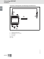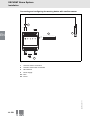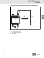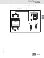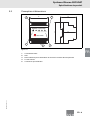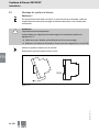
1
ACO T i e f b a u
ufsätze
Abscheiden mit Sicherheit
Bedienungsanleitung
ACO SECURAT Alarmanlage
Titel_Bedienungsanleitung_Securat.indd 2
22.03.2010 08:44:16
Alarmanlage SECURAT
Inhalt
1 Sicherheit ............................................................................ 3
1.1
Allgemeine Sicherheitshinweise....................................................................3
1.2
Verwendete Symbole ....................................................................................3
1.3
Konformitätserklärung ...................................................................................4
1.4
Bestimmungsgemäße Verwendung ..............................................................4
1.5
Wartung ........................................................................................................5
1.6
Lieferung, Transport und Lagerung ...............................................................5
1.7
Installation und Inbetriebnahme ....................................................................5
1.8
Installation in Verbindung mit eigensicheren Kreisen ....................................6
1.9
Reparatur ......................................................................................................6
1.10 Entsorgung ...................................................................................................6
1.11 Angewandte Normen und Richtlinien............................................................7
2 Produktspezifikationen ...................................................... 8
2.1
Funktion ........................................................................................................8
2.2
Produktprogramm .........................................................................................8
2.3
Aufbau und Abmessungen............................................................................9
3 Installation......................................................................... 10
3.1
Montage der Sensoren ...............................................................................10
3.2
Montage der Warnanlage............................................................................14
3.3
Anschluss ...................................................................................................15
4 Inbetriebnahme ................................................................ 20
4.1
Konfiguration der Warnanlage über DIP-Schalter........................................20
5 Betrieb ............................................................................... 22
Alarmmeldungen.........................................................................................22
5.2
Rückstellen der Alarmmeldung ...................................................................22
5.3
Funktionsprüfung ........................................................................................23
242975
2011-11
5.1
DE - 1
DE
Alarmanlage SECURAT
Inhalt
6 Störungsbeseitigung ....................................................... 25
6.1
Fehlersuche und Alarmzustände................................................................ 25
6.2
Anlagenpflege ............................................................................................ 26
7 Technische Daten............................................................. 27
SECURAT®-Alarmanlage........................................................................... 27
Aufstausensor NVF-104/34-PF .................................................................. 28
7.3
Ölschichtsensor KVF-104-PF..................................................................... 28
2011-11
7.1
7.2
242975
DE
2 - DE
Alarmanlage SECURAT
Sicherheit
1
Sicherheit
1.1
Allgemeine Sicherheitshinweise
Die Verantwortung hinsichtlich Planung, Montage, Inbetriebnahme, Betrieb,
Wartung und Demontage liegt beim Betreiber der Anlage.
Die Installation und Inbetriebnahme aller Geräte darf nur durch eingewiesenes
Fachpersonal durchgeführt werden.
Der Schutz von Betriebspersonal und Anlage ist nicht gewährleistet, wenn die
Baugruppe nicht entsprechend ihrer bestimmungsgemäßen Verwendung
eingesetzt wird.
Die für die Verwendung bzw. den geplanten Einsatzzweck zutreffenden Gesetze
bzw. Richtlinien müssen beachtet werden. Die Geräte sind nur für eine
sachgerechte und bestimmungsgemäße Verwendung zugelassen. Bei
Zuwiderhandlung erlischt jegliche Garantie und Herstellerverantwortung.
Die entsprechenden Datenblätter, Konformitätserklärungen und/oder
EG-Baumusterprüfbescheinigungen sind ein integraler Bestandteil dieses
Dokumentes. Das Datenblatt enthält die elektrischen Daten der
EG-Baumusterprüfbescheinigung.
Diese Dokumente finden Sie auf www.aco-tiefbau.de oder wenden Sie sich an
Ihren lokalen Vertreter.
1.2
Verwendete Symbole
Sicherheitsrelevante Symbole
Gefahr!
Dieses Symbol kennzeichnet eine unmittelbar drohende Gefahr.
Bei Nichtbeachten drohen Personenschäden bis hin zum Tod.
Warnung!
Dieses Zeichen warnt vor einer möglichen Störung oder Gefahr.
Bei Nichtbeachten drohen Personenschäden oder schwerste Sachschäden.
Vorsicht!
Dieses Zeichen warnt vor einer möglichen Störung.
242975
2011-11
Bei Nichtbeachten können Geräte oder daran angeschlossene Systeme und
Anlagen bis hin zur völligen Fehlfunktion gestört werden.
DE - 3
DE
Alarmanlage SECURAT
Sicherheit
Informative Symbole
Hinweis!
DE
Dieses Zeichen macht auf eine wichtige Information aufmerksam.
Handlungsanweisung
Dieses Symbol markiert eine Handlungsanweisung.
1.3
Konformitätserklärung
Alle Produkte wurden unter Beachtung geltender europäischer Normen und
Richtlinien entwickelt und gefertigt.
Hinweis!
Eine Konformitätserklärung kann beim Hersteller angefordert werden.
1.4
Bestimmungsgemäße Verwendung
Die Warnanlage ist ein kompaktes Alarmsystem für die Überwachung von
Sensoren im explosionsgefährdeten Bereich der Zone 0 in Öl-/BenzinAbscheideranlagen.
Die Warnanlagen dürfen nur in einem geeigneten Schaltschrank oder im
Montagegehäuse montiert werden.
Die Warnanlage eignet sich:
■
■
■
für die Erkennung der Ölschichtdicke bei Anschluss eines Sensors
für die Erkennung des Höchststandes der Flüssigkeit bei Anschluss eines
Sensors
für die Erkennung der Ölschichtdicke und des Höchststandes der Flüssigkeit
bei Anschluss von zwei Sensoren
An die Warnanlage dürfen nur die folgenden Sensoren angeschlossen werden:
Typencode
Aufstausensor, zur Erkennung von zu hohem
Flüssigkeitsstand
NVF-104/34-PF
Ölschichtensor, zur Erkennung der Ölschichtdicke
KVF-104-PF
242975
2011-11
Beschreibung
4 - DE
Alarmanlage SECURAT
Sicherheit
1.4.1
Kennzeichnung
Alarmanlage
DE
ACO Tiefbau Vertrieb GmbH
Mittelriedstraße 25, 68642 Bürstadt, Germany
SECURAT -Alarmanlage
®
BVS 09 ATEX E 137
II (1)G [Ex ia] IIB
1.5
Wartung
Das Gerät darf nicht mit ätzenden Flüssigkeiten gereinigt werden.
Die Geräte sind wartungsfrei. Um jedoch die einwandfreie Funktion des gesamten
Alarmsystems zu gewährleisten, prüfen Sie die Funktion sowie sämtliche
Sensoren mindestens einmal im Jahr.
1.6
Lieferung, Transport und Lagerung
Überprüfen Sie Verpackung und Inhalt auf Beschädigung.
Überprüfen Sie den Lieferumfang auf Vollständigkeit und Richtigkeit.
Bewahren sie die Originalverpackung auf. Das Gerät sollte immer in der
Originalverpackung eingelagert oder transportiert werden.
Lagern sie das Gerät immer in trockener und sauberer Umgebung. Beachten sie
die zulässige Lagertemperatur (siehe Datenblatt).
1.7
1.7.1
Installation und Inbetriebnahme
Installation der Warnanlage
Das Gerät darf nur außerhalb explosionsgefährdeter Bereiche montiert
werden. Das Gerät darf nicht an Orten installiert werden, an denen aggressive
Dämpfe vorkommen können.
Das Gerät muss bei Installation und Wartung spannungsfrei sein. Erst nach
kompletter Montage und Anschluss der Sensoren darf die Warnanlage an die
Versorgungsspannung angeschlossen werden.
Das Typenschild darf nicht entfernt werden.
1.7.2
Verbindung zu Sensoren für den explosionsgefährdeten Bereich
In Öl-/Benzin-Abscheideranlagen dürfen nur Sensoren angeschlossen werden,
die für die Montage im explosionsgefährlichen Bereich zugelassen sind.
242975
2011-11
Die Schutzart der externen Ausrüstung muss der für das gesamte System
vorgeschriebenen Schutzart entsprechen.
DE - 5
Alarmanlage SECURAT
Sicherheit
1.7.3
Sensorkabel
Sensorkabel dürfen nicht in Kabel- oder Leiterbündeln gemeinsam mit anderen
Stromkreisen verlegt werden. Vermeiden Sie, das Sensorkabel parallel mit
anderen Kabeln zu verlegen, von denen Störsignale ausgehen können, die das
Sensorsignal und damit die Alarmfunktion beeinträchtigen. Der Sensor selbst
darf nicht geerdet werden.
DE
Wenn Sie das Sensorkabel verlängern, beachten Sie die geltenden ATEXVorschriften bezgl. Farbe, Qualität, Beständigkeit. Verwenden Sie ungeschirmtes
Kabel.
1.8
Installation in Verbindung mit eigensicheren Kreisen
Die eigensicheren Stromkreise der Geräte dürfen in explosionsgefährdete
Bereiche geführt werden, hierbei ist insbesondere auf eine sichere Trennung zu
allen nichteigensicheren Stromkreisen zu achten.
Die Ausführung der Installation der eigensicheren Stromkreise ist entsprechend
den geltenden Errichterbestimmungen vorzunehmen.
Für die Zusammenschaltung eigensicherer Feldgeräte mit den eigensicheren
Stromkreisen der zugehörigen Geräte sind die jeweiligen Höchstwerte des
Feldgerätes und des zugehörigen Gerätes im Sinne des Explosionsschutzes zu
beachten (Nachweis der Eigensicherheit). Hierbei ist EN 60079-14/IEC 60079-14
zu beachten. Für die Bundesrepublik Deutschland ist zusätzlich das "Nationale
Vorwort" der DIN EN 60079-14/VDE 0165 Teil 1 zu beachten.
1.9
Reparatur
Die Geräte dürfen nicht repariert, verändert oder manipuliert werden. Im Falle
eines Defektes ist das Produkt immer durch ein Originalgerät zu ersetzen.
1.10
Entsorgung
Die Geräte und das Verpackungsmaterial müssen entsprechend den
einschlägigen Gesetzen und Vorschriften im jeweiligen Land entsorgt werden.
242975
2011-11
In den Geräten sind keine Batterien enthalten, die getrennt entsorgt werden
müssten.
6 - DE
Alarmanlage SECURAT
Sicherheit
1.11
Angewandte Normen und Richtlinien
EN 60079-0:2009
DE
EN 60079-11:2007
EN 60079-26:2007
EN 50178:1997
EN 61326-1:2006
NAMUR NE21:2007
EN 61000-6-4:2007
ATEX-Richtlinie 94/9/EG
EMV-Richtlinie 2004/108/EG
242975
2011-11
Niederspannungsrichtlinie 2006/95/EG
DE - 7
Alarmanlage SECURAT
Produktspezifikationen
Produktspezifikationen
2.1
Funktion
Die Warnanlage überwacht den Zustand von
■
■
einem Aufstausensor oder einem Ölschichtsensor oder
einer Kombination aus Aufstausensor und Ölschichtsensor
in einer Öl-/Benzin-Abscheideranlage. Leuchtdioden am Gerät zeigen Alarm,
Sensorstörung sowie den Anlagen- und Sensorzustand an. Im Alarmfall ertönt
zusätzlich ein akustisches Signal.
2.2
Produktprogramm
Warnanlage
Beschreibung
Typencode
Eigensichere Warnanlage, 230 V AC
SECURAT®
Sensoren
Beschreibung
Typencode
Aufstausensor, zur Erkennung von zu hohem
Flüssigkeitsstand
NVF-104/34-PF
Ölschichtensor, zur Erkennung der Ölschichtdicke
KVF-104-PF
Zubehör
Typencode
Kabelanschlussdose IP67
NVO5-VD
Kabelverbinder IP68 für einen Sensor
LAL-SK2
Gehäuse mit DIN-Schiene
NVO5-KV
2011-11
Beschreibung
242975
DE
2
8 - DE
Alarmanlage SECURAT
Produktspezifikationen
2.3
Aufbau und Abmessungen
70
5
DE
58
1
®
SECURAT -Alarmanlage
Netz
Funftions- Alarm
Alarm
kontrolle Aufstau Schichtdicke
86
Alarm
Reset
54
ACO Tiefbau
4
3
2
Abbildung 2.1
DIP-Schalter
2
LEDs
3
Anschlüsse für Versorgung und potentialfreie Kontakte
4
Reset-Taste
5
Sensoranschlüsse
242975
2011-11
1
DE - 9
Alarmanlage SECURAT
Installation
3
3.1
Montage der Sensoren
Lesen Sie das Kapitel Sicherheit und besonders den Abschnitt Installation und
Inbetriebnahme (siehe Kapitel 1.7) vor der Montage des Sensors. Entfernen Sie
nicht das Typenschild.
Warnung!
Kurzschlussgefahr
Verletzungen und Beschädigung des Gerätes können bei Arbeiten unter
Spannung auftreten.
■
■
Trennen Sie vor Arbeiten am Gerät immer zuerst die Versorgungsspannung.
Schließen Sie das Gerät erst nach abgeschlossenen Arbeiten an die
Versorgungsspannung an.
2011-11
Beachten Sie bei der Installation die Anleitungen des Öl-/BenzinAbscheideranlagen-Herstellers. Sorgen Sie dafür, dass die Aufhängevorrichtung
des Sensors eine korrekte Einhaltung der Höhenposition dauerhaft gewährleistet.
Dabei ist die Vorrichtung möglichst so zu befestigen, dass sie vom
Abstiegsschacht der Abscheideranlage erreichbar ist, um das Anheben des
Sensors beim Entleeren (Entsorgen) oder Warten der Öl-/BenzinAbscheideranlage zu ermöglichen.
242975
DE
Installation
10 - DE
Alarmanlage SECURAT
Installation
Die genaue Höheneinstellung erfolgt über die Befestigung des Sensors. Für die
Befestigung in einem Betonbehälter, verwenden Sie ein Befestigungsset (siehe
Abbildung unten). Bei Behältern, Tanks oder Abscheideranlagen aus anderen
Materialen, z. B. Kunststoff oder Metall, verwenden Sie entsprechend andere
Befestigungsmöglichkeiten (Schrauben und Dübel).
2
1
Abbildung 3.1
Montage mit Kabelverbinder und Befestigungsset
1
Befestigungsset für Sensoren
2
Kabelverbinder für einen Sensor LAL-SK2
Hinweis!
242975
2011-11
Die genaue Einbaulage sowie die Sensorposition entnehmen Sie bitte dem
separaten Datenblatt.
DE - 11
DE
Alarmanlage SECURAT
Installation
3.1.1
Montage des Aufstausensors NVF-104/34-PF
Im Regelfall ist die Unterkante des Sensors einige Zentimeter über dem normalen
Flüssigkeitspegel (Nullwasserlinie) angebracht, und zwar so dicht an der
Nullwasserlinie, dass der Schaltpunkt bei einem eventuellen Überlauf von
Flüssigkeit umschlossen wird. Das tritt ein,
DE
■
■
■
wenn der Koaleszenzfilter verschmutzt ist,
wenn die selbsttätige Verschlusseinrichtung gesperrt ist oder
wenn eine andere Situation zum Überlauf oder zur Verunreinigung der
ölhaltigen Flüssigkeit führt.
Der Schaltpunkt liegt in Höhe der 5 mm-Bohrung auf der Seite des Sensors.
1
A
X
S
L
B
C
Montage des Aufstausensors
Aufstausensor NVF-104/34-PF
A
Luft
B
Öl
C
Wasser
L
Nullwasserlinie
S
Schaltpunkt Sensor
X
Alarmgrenze (maximaler Flüssigkeitspegel)
242975
1
2011-11
Abbildung 3.2
12 - DE
Alarmanlage SECURAT
Installation
3.1.2
Montage des Ölschichtsensors KVF-104-PF
Der Sensor muss bei regulärem Flüssigkeitspegel (Nullwassserlinie) einige
Zentimeter in die Flüssigkeit eingetaucht sein.
Wie weit die Eintauchtiefe im angegebenen Bereich gewählt wird, hängt
■
■
■
vom Typ der Öl-/Benzin-Abscheideranlage,
von der Konstruktion
und der Kapazität ab.
Der Sensor muss immer in die Flüssigkeit eingetaucht sein. Der Schaltpunkt des
Sensors befindet sich zwischen dem isolierten Zwischenstück und dem oberen
Metallteil.
A
L
X
B
1
S
C
242975
2011-11
Abbildung 3.3
Montage des Ölschichtsensors
1
Ölschichtsensor KVF-104-PF
A
Luft
B
Öl
C
Wasser
L
Nullwasserlinie
S
Schaltpunkt Sensor
X
Alarmgrenze (maximale Ölschichtdicke)
DE - 13
DE
Alarmanlage SECURAT
Installation
3.2
Montage der Warnanlage
Hinweis!
DE
Wird das Gerät in einem Gehäuse oder Schaltschrank montiert, beachten Sie die
Montageinstruktionen des Gehäuse- oder Schaltschrankherstellers.
Vorsicht!
Überhitzung
Überschreitet die Außentemperatur bei maximaler Belastung 60 °C, kann das
Gerät beschädigt werden.
■
■
Sorgen sie für ausreichende Belüftung am Montageort.
Halten sie einen Mindestabstand von 5 mm zwischen Geräten auf der
Hutschiene ein.
Warnanlage auf die Hutschiene montieren
Schnappen Sie das Gerät wie folgt auf die Hutschiene auf:
Click!
242975
2011-11
Abbildung 3.4
14 - DE
Alarmanlage SECURAT
Installation
3.3
Anschluss
Lesen Sie das Kapitel Sicherheit und besonders den Abschnitt Installation und
Inbetriebnahme (siehe Kapitel 1.7) vor der Montage des Sensors. Entfernen Sie
nicht das Typenschild.
Warnung!
Kurzschlussgefahr
Verletzungen und Beschädigung des Gerätes können bei Arbeiten unter
Spannung auftreten.
■
■
Trennen Sie vor Arbeiten am Gerät immer zuerst die Versorgungsspannung.
Schließen Sie das Gerät erst nach abgeschlossenen Arbeiten an die
Versorgungsspannung an.
Beachten Sie beim Anschluss die korrekte Verpolung der Sensorkabel. Der
Schleifenwiderstand des Verlängerungskabels darf für den Sensor:
■
■
KVF-104-PF 20 Ω nicht überschreiten.
NVF-104/34-PF 10 Ω nicht überschreiten.
Verwenden Sie zur Verlängerung des Sensorkabels Kabelverbinder LAL-SK2.
Hinweis!
Vermeiden Sie, das Sensorkabel parallel mit anderen Kabeln zu verlegen, von
denen Störsignale ausgehen können, die das Sensorsignal und damit die
Alarmfunktion beeinträchtigen. Verwenden Sie für jeden Sensor ungeschirmtes 2adriges Kabel.
Für eine einwandfreie Funktion der Warnanlage dürfen folgende maximale
Sensorkabellängen nicht überschritten werden:
2
■ Bei einem Leitungsquerschnitt von 0,75 mm beträgt die maximale
Kabellänge 190 m.
2
■ Bei einem Leitungsquerschnitt von 1 mm beträgt die maximale Kabellänge
250 m.
Das Produkt ist ein Klasse II-Gerät (mit verstärkter Isolierung). Schließen Sie die
Versorgung wie folgt an:
■
Klemme 7: Phase (F/L2)
Klemme 6: Null (N/L1)
■
Klemme 5: Erde (Schleifenklemme)
■
Über die Klemmen 1 bis 3 und 10 bis 12 können Sie zusätzliche Relais
anschließen, die z. B. einen Fernalarm oder den Anschluss an eine zentrale
Überwachungsanlage ermöglichen.
242975
2011-11
Hinweis!
DE - 15
DE
Alarmanlage SECURAT
Installation
Anschluss und Konfiguration der Warnanlage mit Aufstausensor
DE
1
bn
13
bu
15
22 23 24
2
3
1
2
3
4
5
6
7
8
OFF
ON
1 2 3
5 6 7
230 V AC
10 11 12
4
Abbildung 3.5
1
Anschluss Aufstausensor
2
Aufstausensor NVF-104/34-PF
3
DIP-Schalter
4
Versorgung
bu blau
242975
2011-11
bn braun
16 - DE
Alarmanlage SECURAT
Installation
Anschluss und Konfiguration der Warnanlage mit Ölschichtsensor
DE
1
bn
13
15
bu
22 23 24
2
3
1
2
3
4
5
6
7
8
OFF
ON
1 2 3
5 6 7
230 V AC
10 11 12
4
Abbildung 3.6
1
Anschluss Ölschichtsensor
2
Ölschichtsensor KVF-104-PF
3
DIP-Schalter
4
Versorgung
bu blau
242975
2011-11
bn braun
DE - 17
Alarmanlage SECURAT
Installation
Anschluss und Konfiguration der Warnanlage mit Aufstausensor und
Ölschichtsensor
DE
2
1
bn
13
bu
bn
15
bu
22 23 24
4
3
5
1
2
3
4
5
6
7
3
8
OFF
ON
1 2 3
5 6 7
230 V AC
10 11 12
4
6
Abbildung 3.7
1
Anschluss Aufstausensor
2
Anschluss Ölschichtsensor
3
Aufstausensor NVF-104/34-PF
4
Ölschichtsensor KVF-104-PF
5
DIP-Schalter
6
Versorgung
bu blau
242975
2011-11
bn braun
18 - DE
Alarmanlage SECURAT
Installation
Sie können die Sensoren über eine Anschlussdose anschließen. Im folgenden
Bild ist der Anschluss mit der Anschlussdose NVO5-VD dargestellt.
DE
Anschluss und Konfiguration der Warnanlage mit
Anschlussdose NVO5-VD
1
A
A
B
13
C
15
C
D
22 23 24
2
1 2 3
B
D
5 6 7
3
10 11 12
230 V AC
Abbildung 3.8
Anschlussdose NVO5-VD
2
Aufstausensor NVF-104/34-PF
3
Ölschichtsensor KVF-104-PF
242975
2011-11
1
DE - 19
Alarmanlage SECURAT
Inbetriebnahme
Inbetriebnahme
4.1
Konfiguration der Warnanlage über DIP-Schalter
Die DIP-Schalter befinden sich an der rechten Geräteseite (siehe Kapitel 2.3).
OFF
ON
1 2 3 4 5 6 7 8
NVF sensor
KVF sensor
Acoustic alarm
Relay setting
Relay setting
Repeat alarm in 24 hours
Reset key
Not in use
Refer servicing to qualified personel.
Do not change switch position when energized.
Übersicht über die DIP-Schalter der Warnanlage
2011-11
Abbildung 4.1
242975
DE
4
20 - DE
Alarmanlage SECURAT
Inbetriebnahme
Die folgende Tabelle zeigt die möglichen Konfigurationseinstellungen.
Schalter
DIP 1
Beschreibung
DE
NVF sensor
(NVF-104/34-PF)
ON
angeschlossen
OFF
nicht angeschlossen
DIP 2
KVF sensor
(KVF-104-PF)
ON
angeschlossen
OFF
nicht angeschlossen
DIP 3
Acoustic alarm
(akustischer Alarm)
ON
Akustischer Alarm eingeschaltet.
OFF
Akustischer Alarm ausgeschaltet.
Relay setting
(Relaiseinstellung)
ON
Relais 1 und 2 schalten bei allen Alarmzuständen, steht
das Ereignis des Alarms nicht mehr an, schaltet das
Relais 1 automatisch wieder zurück UND Relais 2 bleibt
solange unverändert, bis der Alarm durch die Betätigung
der "ALARM RESET"-Taste quittiert wurde. Es zeigt somit
an, dass ein Alarm vorlag.
DIP 4
DIP 5
DIP 4
ON
Relay setting
(Relaiseinstellung)
DIP 5
DIP 4
OFF
Relay setting
(Relaiseinstellung)
DIP 5
DIP 4
DIP 7
Relay setting
(Relaiseinstellung)
OFF
OFF
Relais 1 und 2 schaltet bei allen Alarmzuständen. Nach 3
Minuten schaltet Relais 2 wieder (auch wenn ein
Alarmzustand ansteht). Endet der Alarmzustand, schaltet
Relais 1 und/oder Relais 2 wieder zurück. Bei Betätigen
der "ALARM RESET"-Taste schalten die Relais wieder.
Relais 1 schaltet bei Alarmzustand auf NVF-Sensor,
Relais 2 schaltet bei Alarmzustand auf KVF-Sensor. Endet
der Alarmzustand, schalten Relais 1 und/oder Relais 2
wieder zurück. Bei Betätigen der "ALARM RESET"-Taste
schalten die Relais wieder.
Relais 1 und 2 schalten bei allen Alarmzuständen egal mit
welchem Sensor. Endet der Alarmzustand, schalten
Relais 1 und Relais 2 wieder zurück. Bei Betätigen der
"ALARM RESET"-Taste schalten die Relais wieder.
Repeat alarm in 24 hours
(Alarmwiederholung in
24 Stunden)
ON
Alarmwiederholung eingeschaltet. Das gilt auch für die
Funktion der Relais 1 und 2.
OFF
Alarmwiederholung ausgeschaltet
Reset key
(ALARM RESETAktivierung)
ON
"ALARM RESET"-Taste ist aktiviert. Der akustische Alarm
und die Alarmrelais können zurückgestellt werden.
OFF
"ALARM RESET"-Taste ist deaktiviert. Der akustische
Alarm und die Alarmrelais können nicht zurückgestellt
werden.
Not in use (nicht belegt)
242975
2011-11
DIP 8
OFF
ON
DIP 5
DIP 6
ON
DE - 21
Alarmanlage SECURAT
Betrieb
Betrieb
5.1
Alarmmeldungen
Die Warnanlage zeigt akustisch und visuell einen Alarmzustand oder
Sensorfehler an. Die entsprechenden LEDs, "Alarm Aufstau" oder
"Alarm Schichtdicke" leuchten solange, bis der Normalzustand wieder erreicht ist.
LED
Zustand
Bedeutung
Gelbe LED "Netz"
leuchtet
Netzspannung liegt am Gerät an. Gerät in Betrieb
blinkt
Inbetriebnahme Aufstausensor
Grüne LED
"Funktionskontrolle"
leuchtet
Kein Fehler oder Alarm aktiv – Normalbetrieb
blinkt
Kein Fehler oder Alarm aktiv, es lag ein Fehler
oder Alarm in der Vergangenheit vor.
Rote LED
"Alarm Aufstau"
leuchtet
Alarm aktiv, Aufstausensor mit Flüssigkeit
bedeckt.
blinkt
Interner Sensorfehler, Kabelbruch oder
Kurzschluss
leuchtet
Alarm aktiv, Ölschichtsensor mit Öl bedeckt.
blinkt
Interner Sensorfehler, Kabelbruch oder
Kurzschluss
Rote LED
"Alarm Schichtdicke"
5.2
Rückstellen der Alarmmeldung
Durch Drücken der Taste "ALARM RESET" wird ein in der Vergangenheit
liegender Alarm zurückgesetzt (blinkende grüne LED).
Besteht der Alarmzustand aktuell, setzt das Drücken der Taste "ALARM RESET"
den akustischen Alarm und das entsprechende Relais 1 und/oder 2 zurück. Die
LEDs der Sensoren leuchten/blinken weiter.
2011-11
Wenn der DIP-Schalter "Repeat alarm in 24 hours" auf ON gesetzt ist, wird der
Alarm nach 24 Stunden wiederholt.
242975
DE
5
22 - DE
Alarmanlage SECURAT
Betrieb
5.3
Funktionsprüfung
Warnanlage
DE
Zum Test der Funktion der Warnanlage kann ein LED- und Relaistest
durchgeführt werden.
Zum Starten der Funktionsprüfung drücken sie die Taste "ALARM RESET" etwa
3 Sekunden lang:
1. das Steuergerät geht in den Testmodus,
2. jede LED leuchtet nacheinander für 1 Sekunde,
3. beide Relais werden nacheinander für 1 Sekunde geschalten,
4. danach ertönt ein akustisches Signal und die
5. Warnanlage geht wieder in den aktuellen Status zurück.
Aufstausensor
Warnung!
Verbrennungsgefahr
Die Sensorspitze ist heiß.
Nicht berühren.
Prüfung des Normalzustandes
1. Nehmen Sie den Sensor aus der Öl-/Benzin-Abscheideranlage heraus.
2. Waschen und trocknen Sie den Sensor.
3. Lassen Sie den Sensor frei schwebend in der Luft hängen.
An der Warnanlage leuchtet oder blinkt die grüne LED
"Funktionskontrolle".
Prüfung der Alarmsituation
Tauchen Sie den Sensor in Flüssigkeit ein (Schaltpunkt muss untergetaucht sein).
242975
2011-11
Die rote LED "Alarm Aufstau" leuchtet ggf. ertönt ein akustisches Signal.
DE - 23
Alarmanlage SECURAT
Betrieb
Ölschichtsensor
Prüfung des Normalzustandes
DE
1. Nehmen Sie den Sensor aus der Öl-/Benzin-Abscheideranlage heraus.
2. Waschen und trocknen Sie den Sensor.
3. Nehmen Sie den Sensor in die Hand (ohne Handschuhe).
4. Berühren Sie dabei nur das obere und untere Metallteil.
An der Warnanlage leuchtet oder blinkt die grüne LED
"Funktionskontrolle".
Prüfung der Alarmsituation
Lassen Sie den Sensor frei schwebend in der Luft hängen.
242975
2011-11
Die LED "Alarm Schichtdicke" leuchtet ggf. ertönt ein akustisches Signal.
24 - DE
Alarmanlage SECURAT
Störungsbeseitigung
6
Störungsbeseitigung
6.1
Fehlersuche und Alarmzustände
DE
Hinweis!
Falls eingeschaltet (DIP-Schalter "Acoustic alarm" auf ON) ertönt im Alarm- und
Sensorstörungsfall ein akustisches Signal.
LED-Anzeige
Ursache
Maßnahme
Alle LEDs sind aus.
Warnanlage ist nicht in
Betrieb.
Überprüfen Sie ob die
Versorgunsspannung angeschlossen ist.
LED "Netz" blinkt.
Anlage wird in Betrieb
genommen. Aufstausensor
in Aufwärmphase
(ca. 10 s ... 20 s).
Abwarten bis Aufstausensor
Betriebstemperatur erreicht hat.
■
■
■
■
■
■
■
■
■
■
■
Kein aktueller Alarm. Die Warnanlage arbeitet normal.
LED "Netz" leuchtet.
LED "Funktionskontrolle"
blinkt.
Kein aktueller Alarm. Es lag
ein Alarm in der
Vergangenheit vor.
1. Kontrollieren Sie den
Abscheiderzustand.
2. Drücken Sie die "ALARM RESET"Taste.
LED "Netz" leuchtet.
LED "Alarm Aufstau"
leuchtet.
Überhöhter
Flüssigkeitspegel
Kontrollieren Sie unbedingt den
Abscheiderzustand. Treffen Sie ggf.
Maßnahmen, um die Alarmsituation zu
stoppen. Die Alarmsituation kann
entstehen bei:
■
verstopftem Koaleszenzfilter oder
■
defektem oder verstopftem Abfluss.
LED "Netz" leuchtet.
LED "Alarm Aufstau"
blinkt.
Sensorfehler oder
Kabelbruch
Sensor und Sensorinstallation überprüfen
und ggf. Aufstausensor austauschen.
LED "Netz" leuchtet.
LED "Alarm Schichtdicke"
leuchtet.
Maximale Ölschichtdicke
erreicht.
Kontrollieren Sie unbedingt den
Abscheiderzustand. Entleeren
(entsorgen) Sie ggf. die Öl-/BenzinAbscheideranlage.
LED "Netz" leuchtet.
LED "Alarm Schichtdicke"
blinkt.
Sensorfehler oder
Kabelbruch
Sensor und Sensorinstallation überprüfen
und ggf. Ölschichtsensor austauschen.
242975
2011-11
■
LED "Netz" leuchtet.
LED "Funktionskontrolle"
leuchtet.
DE - 25
Alarmanlage SECURAT
Störungsbeseitigung
6.2
Anlagenpflege
Verschmutzte Sensoren können Fehlalarme auslösen. Reinigen Sie den Sensor
mindestens einmal im Jahr. Säubern sie insbesondere die Sensorspitze mit
fettlösendem Reinigungsmittel von allen Öl-, Fett- und sonstigen
Schmutzrückständen.
242975
2011-11
DE
26 - DE
Alarmanlage SECURAT
Technische Daten
7
Technische Daten
7.1
SECURAT®-Alarmanlage
DE
Versorgung
Bemessungsspannung
230 V AC ± 10%, 50 Hz ... 60 Hz
Leistungsaufnahme
6 VA
Max. Sicherung
10 A
Überspannungskategorie
Anschluss
III
Klemmen 5, 6, 7
Sicherheitstechnische Maximalspannung
Um
253 V
Anschluss Aufstausensor NVF-104/34-PF
Uo
Klemmen 13, 15
21,0 V
Po
1,16 W (Kennlinie trapezförmig)
Co
0,5 µF
Eingang
Io
256 mA
Ro
165,7 Ω
Lo
0,5 mH
Anschluss Ölschichtsensor KVF-104-PF
Klemmen 22, 24
Uo
Io
10,5 V
92,2 mA
Ro
114,0 Ω
Po
0,25 W (Kennlinie linear)
Co
Lo
3,1 µF
5 mH
Ausgang
Anschluss Relais 1
Klemmen 1, 2, 3
Anschluss Relais 2
Ausgang
Klemmen 10, 11, 12
potentialfreier Wechselkontakt
Kontaktbelastung
250 V AC/4 A/100 VA
Sicherheitstechnische Maximalspannung
Um
253 V
Galvanische Trennung
Ausgang/Versorgung
Ausgang/Ausgang
242975
2011-11
Umgebungsbedingungen
verstärkte Isolierung nach EN 50178,
Bemessungsisolatonsspannung 300 Veff
verstärkte Isolierung nach EN 50178,
Bemessungsisolatonsspannung 300 Veff
Umgebungstemperatur
Mechanische Daten
-25 °C ... 60 °C (248 K ... 333 K)
Masse
ca. 325 g
Schutzart
IP20
Befestigung
Abmessungen
DIN-Hutschiene
70 mm x 86 mm x 58 mm
DE - 27
Alarmanlage SECURAT
Technische Daten
7.2
Aufstausensor NVF-104/34-PF
Versorgung
Bemessungsspannung
Umgebungsbedingungen
Umgebungstemperatur
Mechanische Daten
Schutzart
Anschluss
Material
Kabel
Masse
Abmessungen
DE
7.3
24 V DC
-20 °C ... 50 °C (253 K ... 323 K)
IP68
Kabel
Edelstahl
5m
ca. 315 g
∅20 mm x 124 mm
Ölschichtsensor KVF-104-PF
13 V DC
-20 °C ... 60 °C (253 K ... 333 K)
IP68
Kabel
Edelstahl
5m
ca. 520 g
∅31,6 mm x 138 mm
242975
2011-11
Versorgung
Bemessungsspannung
Umgebungsbedingungen
Umgebungstemperatur
Mechanische Daten
Schutzart
Anschluss
Material
Kabel
Masse
Abmessungen
28 - DE
SECURAT Alarm System
Content
1 Safety ................................................................................... 3
1.1
General safety instructions ............................................................................3
1.2
Used Symbols...............................................................................................3
1.3
Declaration of Conformity..............................................................................4
1.4
Intended Use ................................................................................................4
1.5
Maintenance .................................................................................................5
1.6
Delivery, Transport and Storage ....................................................................5
1.7
Installation and Commissioning ....................................................................5
1.8
Installation in connection with intrinsically safe circuits..................................6
1.9
Repair ...........................................................................................................6
1.10 Disposal........................................................................................................6
1.11 Applied Standards and Directives .................................................................7
2 Product Specifications....................................................... 8
2.1
Function ........................................................................................................8
2.2
Product Program...........................................................................................8
2.3
Design and Dimensions ................................................................................9
3 Installation......................................................................... 10
3.1
Mounting of the Sensors .............................................................................10
3.2
Mounting of the Warning Device .................................................................14
3.3
Connection .................................................................................................15
4 Commissioning................................................................. 20
4.1
Configuring the Warning Device using DIP Switches ..................................20
5 Operation........................................................................... 22
Alarm Signals..............................................................................................22
5.2
Resetting the Alarm Signal..........................................................................22
5.3
Function Testing..........................................................................................23
242975
2011-11
5.1
EN - 1
EN
SECURAT Alarm System
Content
6 Troubleshooting ............................................................... 25
6.1
Troubleshooting and Alarm States .............................................................. 25
6.2
System Care............................................................................................... 26
7 Technical specifications .................................................. 27
7.1
SECURAT® Alarm System ......................................................................... 27
7.2
Overflow Sensor NVF-104/34-PF............................................................... 28
7.3
Oil Level Sensor KVF-104-PF .................................................................... 28
242975
2011-11
EN
2 - EN
SECURAT Alarm System
Safety
1
Safety
1.1
General safety instructions
The plant owner is responsible for its planning, installation, commissioning,
operation, maintenance and disassembly.
Installation and commissioning of all devices must be performed by a trained
professional only.
Protection of operating personnel and the system is not ensured if the product is
not used in accordance with its intended purpose.
Laws and regulations applicable to the usage or the intended purpose must be
observed. The devices are only approved for appropriate and intended use.
Ignoring these instructions will void any warranty and absolve the manufacturer
from any liability.
The Declaration of Conformity, Certificate of Compliance, Statement of
Conformity, EC-type-examination certificate and data sheets are an integral part of
this document.
The data sheet contains the electrical data of the Declaration of Conformity, the
Certificate of Compliance and the EC-type-examination certificate.
The documents mentioned are available from www.aco.com or contact your local
representative.
1.2
Used Symbols
Safety-relevant Symbols
Danger!
This symbol indicates a warning about a possible danger.
In case of ignoring the consequences may range from personal injury to death.
Warning!
This symbol indicates a warning about a possible fault or danger.
In case of ignoring the consequences may cause personal injury or heaviest
property damage.
Caution!
This symbol warns of a possible fault.
242975
2011-11
In case of ignoring the devices and any connected facilities or systems may be
interrupted or fail completely.
EN - 3
EN
SECURAT Alarm System
Safety
Informative Symbols
Note!
This symbol brings important information to your attention.
Action
This symbol marks an acting paragraph.
1.3
Declaration of Conformity
All products have been developed and manufactured taking into consideration
applicable European standards and regulations.
EN
Note!
A Declaration of Conformity can be requested from the manufacturer.
1.4
Intended Use
The warning device is a compact alarm system for monitoring sensors in the
Zone 0 hazardous area of oil/petrol separators.
The warning devices must only be installed in a suitable control cabinet or
installation housing.
The warning device was designed to detect:
■
■
■
the oil layer thickness if one sensor is connected
the maximum level of the liquid if one sensors is connected
the oil layer thickness and the maximum level of the liquid if two sensors are
connected
Only the following sensors must be connected to the warning device:
Type code
Overflow sensor, for detecting excessively high liquid level
NVF-104/34-PF
Oil level sensor, for detecting of oil layer thickness
KVF-104-PF
242975
2011-11
Description
4 - EN
SECURAT Alarm System
Safety
1.4.1
Marking
Alarm system
ACO Tiefbau Vertrieb GmbH
Mittelriedstraße 25, 68642 Bürstadt, Germany
SECURAT® alarm system
DEMKO 07 ATEX 142587
II (1)G [Ex ia] IIB
1.5
Maintenance
The device must not be cleaned with caustic fluids.
The devices are maintenance-free. However, to guarantee perfect operation of
the complete alarm system, check the operation, including all sensors, at least
once a year.
1.6
Delivery, Transport and Storage
Check the packaging and contents for damage.
Check if you have received every item and if the items received are the ones you
ordered.
Keep the original packaging. Always store and transport the device in the original
packaging.
Always store the device in a clean and dry environment. The permitted storage
temperature (see data sheet) must be considered.
1.7
1.7.1
Installation and Commissioning
Installation of the warning device
The device must only be installed outside potentially explosive zones. The
device must not be installed in places with potentially aggressive vapors.
The device must be free of voltage during installation and maintenance. The
warning system must only be connected to the supply voltage after complete
mounting and connection of the sensors.
The identification plate must not be removed.
1.7.2
Connection to sensors for potentially explosive zone
In oil/petrol separators, only sensors that are certified for installation in potentially
explosive zones may be connected.
242975
2011-11
The type of protection of the external equipment must comply with the protection
type specified for the total system.
EN - 5
EN
SECURAT Alarm System
Safety
1.7.3
Sensor Cables
Sensor cables must not be installed in cable or conductor bundles together with
other current circuits. Avoid installing sensor cables parallel to other cables that
may transmit interfering signals, which impair the sensor signal and thus the alarm
function. The sensor itself must not be grounded.
If you extend the sensor cable, observe the applicable ATEX specifications with
regard to color, quality and durability. Use unshielded cables.
1.8
Installation in connection with intrinsically safe circuits
Installation of the intrinsically safe power circuits of the devices is permitted in
potentially explosive zones, whereby, in particular, safe separation from all nonintrinsically safe power circuits must be guaranteed.
EN
The intrinsically safe current circuits must be installed according to valid setup
regulations.
For the interconnection of the intrinsically safe field devices and the intrinsically
safe power circuits of the associated devices, the respective maximum values of
the field device and the associated device with regard to explosion protection
must be observed (proof of intrinsic safety). EN 60079-14/IEC 60079-14 must be
observed.
1.9
Repair
The devices must not be repaired, changed or manipulated. If there is a defect,
the product must always be replaced with an original device.
1.10
Disposal
Disposal of devices and their packaging material must be performed in
compliance with the applicable laws and guidelines of the corresponding country.
242975
2011-11
The devices do not contain batteries which need to be disposed of separately
from the products.
6 - EN
SECURAT Alarm System
Safety
1.11
Applied Standards and Directives
EN 60079-0:2009
EN 60079-11:2007
EN 60079-26:2007
EN 50178:1997
EN 61326-1:2006
NAMUR NE21:2007
EN 61000-6-4:2007
EN
ATEX Directive 94/9/EC
EMC Directive 2004/108/EC
242975
2011-11
Low Voltage Directive 2006/95/EC
EN - 7
SECURAT Alarm System
Product Specifications
2
2.1
Product Specifications
Function
The warning device monitors the status of
■
■
an overflow sensor or an oil level sensor, or
a combination of an overflow sensor and an oil level sensor
in an oil/petrol separator. LEDs on the device indicate an alarm, sensor fault and
system and sensor status. In the event of an alarm, an additional acoustic signal
sounds.
2.2
Product Program
Warning device
Description
Type code
Intrinsically safe warning device, 230 V AC
SECURAT®
Sensors
Description
Type code
Overflow sensor, for detecting excessively high liquid level
NVF-104/34-PF
Oil level sensor, for detecting of oil layer thickness
KVF-104-PF
Accessories
Type code
Connection box IP67
NVO5-VD
Cable connector IP68 for one sensor
LAL-SK2
Installation housing with DIN mounting rail
NVO5-KV
2011-11
Description
242975
EN
8 - EN
SECURAT Alarm System
Product Specifications
2.3
Design and Dimensions
70
5
58
1
®
SECURAT -Alarmanlage
Netz
Funftions- Alarm
Alarm
kontrolle Aufstau Schichtdicke
86
Alarm
Reset
54
EN
ACO Tiefbau
4
3
2
Figure 2.1
DIP switches
2
LEDs
3
Connections for power supply and potential-free contacts
4
Reset button
5
Sensor connections
242975
2011-11
1
EN - 9
SECURAT Alarm System
Installation
3
Installation
3.1
Mounting of the Sensors
Read the Safety chapter, paying particular attention to the section covering
Installation and Commissioning (see chapter 1.7) before mounting the sensor. Do
not remove the identification plate.
Warning!
Risk of short circuit
Injuries and damage to the device are possible when working with live parts.
EN
■
Before working on the device, always disconnect the supply voltage.
■
Connect the device to the supply voltage only after completion of the work.
242975
2011-11
During installation, refer to the instructions provided by the oil/petrol separator
manufacturer. Ensure that the suspension mechanism keeps the sensor
permanently at the correct height. Where possible, secure the device in a position
where it can be reached from the manhole opening so that it can be removed
when emptying (disposal) or carrying out maintenance work on the oil/petrol
separator.
10 - EN
SECURAT Alarm System
Installation
The precise height of the sensor depends on how it is mounted. When mounting
in a concrete tank, for example, use a mounting set (see figure below). For
containers, tanks or separators made from other materials, such as plastic or
metal, use the appropriate alternative mounting options (screws and dowels).
2
1
EN
Figure 3.1
Mounting using cable connector and mounting set
1
Mounting set for sensors
2
Cable connector for one sensor LAL-SK2
Note!
242975
2011-11
For exact mounting position and the sensor position, please refer to the separate
data sheet.
EN - 11
SECURAT Alarm System
Installation
3.1.1
Mounting the NVF-104/34-PF Overflow Sensor
Usually, the sensor is mounted with the lower edge a few centimeters above the
normal liquid level (water zero line) in a position so close to the water zero line that
the switching point is surrounded by liquid when an overflow occurs. This occurs
■
if the coalescence filter is dirty,
if the automatic closure device is blocked, or
■
if another situation causes the oily liquid to overflow or become contaminated.
■
The switching point is at the same level as the 5 mm hole on the side of the
sensor.
EN
1
A
X
S
L
B
C
Mounting the overflow sensor
Overflow sensor NVF-104/34-PF
A
Air
B
Oil
C
Water
L
Water zero line
S
Sensor switching point
X
Alarm limit (maximum liquid level)
242975
1
2011-11
Figure 3.2
12 - EN
SECURAT Alarm System
Installation
3.1.2
Mounting the KVF-104-PF Oil Level Sensor
The sensor must be immersed a few centimeters when the liquid is at its normal
level (water zero line).
The exact immersion depth depends on
■
■
■
the type of oil/petrol separator,
its design
and its capacity.
The sensor must always be immersed in the liquid. The sensor switching point is
located between the insulated connecting piece and the top metal section.
EN
A
L
X
B
1
S
C
Mounting the oil level sensor
1
Oil level sensor KVF-104-PF
A
Air
B
Oil
C
Water
L
Water zero line
S
Sensor switching point
X
Alarm limit (maximum oil layer thickness)
242975
2011-11
Figure 3.3
EN - 13
SECURAT Alarm System
Installation
3.2
Mounting of the Warning Device
Note!
If the device is installed in a housing or switch cabinet, note the mounting
instructions of the housing or switch cabinet manufacturer.
Caution!
Overheating
If the external temperature exceeds a maximum of 60 °C, the device may be
damaged.
EN
■
■
Ensure sufficient ventilation at the installation location.
Maintain a minimum distance of 5 mm between the devices on the
DIN mounting rail.
Mount the warning device on the DIN mounting rail
Clip the device on the DIN mounting rail as follows:
Click!
242975
2011-11
Figure 3.4
14 - EN
SECURAT Alarm System
Installation
3.3
Connection
Read the Safety chapter and, in particular, the section on Installation and
Commissioning (see chapter 1.7 before connecting the device. Do not remove the
identification plate.
Warning!
Risk of short circuit
Injuries and damage to the device are possible when working with live parts.
■
■
Before working on the device, always disconnect the supply voltage.
Connect the device to the supply voltage only after completion of the work.
Take care not to reverse the polarity when connecting the sensor cable. The loop
resistance of the extension cable should not exceed
■
■
20 Ω for the sensor KVF-104-PF.
10 Ω for the sensor NVF-104/34-PF.
For extending the sensor cable, use cable connector LAL-SK2.
Note!
Avoid installing sensor cables parallel to other cables that may transmit interfering
signals, which impair the sensor signal and thus the alarm function. Use
unshielded 2-wire cable for each sensor.
To ensure perfect operation of the warning device, do not exceed:
2
■ the max. cable length of 190 m with a cross-section of 0.75 mm .
2
■ the max. cable length of 250 m with a cross-section of 1 mm .
The product is a Class II device (with reinforced insulation). Connect the power
supply as follows:
■
■
■
Terminal 7: phase (F/L2)
Terminal 6: zero (N/L1)
Terminal 5: ground (loop terminal)
Note!
242975
2011-11
Additional relays can be connected via terminals 1 to 3 and 10 to 12. They can be
used, for example, for an external alarm or the connection to a central monitoring
system.
EN - 15
EN
SECURAT Alarm System
Installation
Connecting and configuring the warning device with overflow sensor
1
bn
13
bu
15
22 23 24
2
3
EN
1
2
3
4
5
6
7
8
OFF
ON
1 2 3
5 6 7
230 V AC
10 11 12
4
Figure 3.5
1
Overflow sensor connection
2
Overflow sensor NVF-104/34-PF
3
DIP switches
4
Power supply
bu blue
242975
2011-11
bn brown
16 - EN
SECURAT Alarm System
Installation
Connecting and configuring the warning device with oil level sensor
1
bn
13
15
bu
22 23 24
2
3
1
2
3
4
5
6
7
EN
8
OFF
ON
1 2 3
5 6 7
230 V AC
10 11 12
4
Figure 3.6
1
Oil level sensor connection
2
Oil level sensor KVF-104-PF
3
DIP switches
4
Power supply
bu blue
242975
2011-11
bn brown
EN - 17
SECURAT Alarm System
Installation
Connecting and configuring the warning device with overflow sensor and
oil level sensor
2
1
bn
13
bu
bn
15
bu
22 23 24
EN
4
3
5
1
2
3
4
5
6
7
3
8
OFF
ON
1 2 3
5 6 7
230 V AC
10 11 12
4
6
Figure 3.7
1
Overflow sensor connection
2
Oil level sensor connection
3
Overflow sensor NVF-104/34-PF
4
Oil level sensor KVF-104-PF
5
DIP switches
6
Power supply
bu blue
242975
2011-11
bn brown
18 - EN
SECURAT Alarm System
Installation
You can connect the sensors via a connection box. The following diagram
illustrates the connection to connection box NVO5-VD.
Connecting and configuring the warning device with
connection box NVO5-VD
1
A
A
B
13
C
15
C
D
EN
22 23 24
2
1 2 3
B
D
5 6 7
3
10 11 12
230 V AC
Figure 3.8
Connection box NVO5-VD
2
Overflow sensor NVF-104/34-PF
3
Oil level sensor KVF-104-PF
242975
2011-11
1
EN - 19
SECURAT Alarm System
Commissioning
4
Commissioning
4.1
Configuring the Warning Device using DIP Switches
The DIP switches are located on the right of the device (see chapter 2.3).
OFF
ON
1 2 3 4 5 6 7 8
NVF sensor
KVF sensor
Acoustic alarm
EN
Relay setting
Relay setting
Repeat alarm in 24 hours
Reset key
Not in use
Refer servicing to qualified personel.
Do not change switch position when energized.
Overview of the warning device DIP switches
242975
2011-11
Figure 4.1
20 - EN
SECURAT Alarm System
Commissioning
The following table contains a list of possible configuration settings.
Switches
DIP 1
DIP 2
DIP 3
DIP 4
Description
NVF sensor
(NVF-104/34-PF)
ON
connected
OFF
not connected
KVF sensor
(KVF-104-PF)
ON
connected
OFF
not connected
Acoustic alarm
ON
Acoustic alarm on.
OFF
Acoustic alarm off.
ON
Relays 1 and 2 switch, irrespective of the alarm states. If
the alarm event is no longer present, relay 1 automatically
switches back AND relay 2 remains unchanged until the
alarm is cleared by pressing the "ALARM RESET" button.
It shows that an alarm occurred.
Relay setting
DIP 5
DIP 4
ON
Relay setting
DIP 5
DIP 4
OFF
Relay setting
DIP 5
DIP 4
OFF
ON
Relay setting
DIP 5
OFF
OFF
DIP 6
Repeat alarm in 24 hours
DIP 7
Reset key (ALARM
RESET activation)
Relays 1 and 2 switch, irrespective of the alarm states.
After 3 minutes, relay 2 switches again (even if an alarm
status is present). Relay 1 and/or relay 2 are reset when
the sensor no longer has an alarm status. Pressing the
"ALARM RESET" button switches the relays again.
In the case of active alarm status, relay 1 switches to NVF
sensor and relay 2 switches to KVF. Relay 1 and/or relay 2
are reset when the sensor no longer has an alarm status.
Pressing the "ALARM RESET" button switches the relays
again.
Relays 1 and 2 switch irrespective of the alarm states and
with which sensor. Relay 1 and relay 2 are reset when the
sensor no longer has an alarm status. Pressing the
"ALARM RESET" button switches the relays again.
ON
Repeat alarm on. This also applies to the function of
relays 1 and 2.
OFF
Repeat alarm off.
ON
"ALARM RESET" button is activated. The acoustic alarm
and the alarm relay can be reset.
OFF
"ALARM RESET" button is deactivated. The acoustic
alarm and the alarm relay cannot be reset.
Not in use
242975
2011-11
DIP 8
ON
EN - 21
EN
SECURAT Alarm System
Operation
5
Operation
5.1
Alarm Signals
The warning device indicates an alarm status or sensor fault both visually and
acoustically. The respective LEDs "Alarm Aufstau" or "Alarm Schichtdicke" are
illuminated until the system returns to a normal status.
EN
5.2
LED
Status
Meaning
Yellow LED "Netz"
(supply)
lights up
The device is connected to the power supply.
Device in operation
flashes
Commissioning the overflow sensor
Green LED
"Funktionskontrolle"
(system OK)
lights up
No errors or alarms active – normal operation
flashes
No alarm or error active, there was an alarm or
error in the past.
Red LED "Alarm
Aufstau" (overflow
alarm)
lights up
Alarm active, overflow sensor is covered with
liquid.
flashes
Internal sensor fault, lead breakage or shortcircuit
Red LED "Alarm
Schichtdicke" (high
oil level alarm)
lights up
Alarm active, oil level sensor is covered with oil.
flashes
Internal sensor fault, lead breakage or shortcircuit
Resetting the Alarm Signal
Pressing the "ALARM RESET" button resets an alarm that occurred in the past
(flashing green LED).
If the alarm status is still active, pressing the "ALARM RESET" button resets the
acoustic alarm and the relevant relay (1 and/or 2). The sensor LEDs remain
lit/continue to flash.
242975
2011-11
If the DIP switch "Repeat alarm in 24 hours" is set to ON, the alarm is repeated
after 24 hours.
22 - EN
SECURAT Alarm System
Operation
5.3
Function Testing
Warning device
Operation of the warning device can be checked by performing a LED and relay
test.
To start the function test, press and hold the "ALARM RESET" button for about
3 seconds:
1. the control unit switches to test mode,
2. each LED lights up in turn for 1 second,
3. both relays are activated in turn for 1 second,
EN
4. the acoustic signal then sounds and the
5. warning device returns to the current status.
Overflow sensor
Warning!
Danger of burning
The sensor tip is hot.
Do not touch.
Checking the normal status
1. Remove the sensor from oil/petrol separator.
2. Wash and dry the sensor.
3. Suspend the sensor freely in air.
The green LED "Funktionskontrolle" (system OK) on the warning device
flashes or lights up.
Checking the alarm situation
Immerse the sensor in liquid (the switching point must be immersed).
242975
2011-11
The red LED "Alarm Aufstau" (overflow alarm) lights and, if applicable, an
acoustic signal sounds.
EN - 23
SECURAT Alarm System
Operation
Oil level sensor
Checking the normal status
1. Remove the sensor from oil/petrol separator.
2. Wash and dry the sensor.
3. Hold the sensor in your hand (no gloves).
4. Only touch the upper and lower metal section.
The green LED "Funktionskontrolle" (system OK) on the warning device
flashes or lights up.
Checking the alarm situation
EN
Suspend the sensor freely in air.
242975
2011-11
The red LED "Alarm Schichtdicke" (high oil level alarm) lights up and, if
applicable, an acoustic signal sounds.
24 - EN
SECURAT Alarm System
Troubleshooting
6
Troubleshooting
6.1
Troubleshooting and Alarm States
Note!
If the DIP switch "Acoustic alarm" is set to ON, an acoustic signal sounds when an
alarm or sensor fault occurs.
LED indication
Cause
Action
All LEDs are off.
The warning device is not
functioning.
Check that the supply voltage is
connected.
LED "Netz" (supply) flashes.
System is being put into
operation. Overflow sensor
in warm-up phase
(approx. 10 s ... 20 s).
Wait until the overflow sensor has reached
operating temperature.
■
■
■
■
■
■
■
LED "Netz" (supply) lights
up.
LED "Funktionskontrolle"
(system OK) lights up.
No alarm at present. The warning system is operating normally.
LED "Netz" (supply) lights
up.
LED "Funktionskontrolle"
(system OK) flashes.
No alarm at present. An
alarm occurred in the past.
1. Check the status of the separator.
2. Press the "ALARM RESET" button.
LED "Netz" (supply) lights
up.
LED "Alarm Aufstau"
(overflow alarm) lights up.
Excessive liquid level
It is essential to check the separator
status. If necessary, takes measures to
stop the alarm situation. The alarm
situation can result if:
■
the coalescence filter is blocked or
■
the drain is defective or blocked.
LED "Netz" (supply) lights
up.
LED "Alarm Aufstau"
(overflow alarm) flashes.
Sensor fault or lead
breakage
Check sensor and sensor installation and
replace the overflow sensor, if necessary.
242975
2011-11
■
EN
EN - 25
SECURAT Alarm System
Troubleshooting
LED indication
■
■
■
■
EN
Cause
Action
LED "Netz" (supply) lights
up.
LED "Alarm Schichtdicke"
(high oil level alarm) lights
up.
Maximum oil layer thickness
reached.
It is essential to check the separator
status. Empty (dispose of) the oil/petrol
separator, if necessary.
LED "Netz" (supply) lights
up.
LED "Alarm Schichtdicke"
(high oil level alarm)
flashes.
Sensor fault or lead
breakage
Check sensor and sensor installation and
replace oil level sensor, if necessary.
6.2
System Care
242975
2011-11
Dirty sensors may trigger false alarms. Clean the sensor at least once a year. Pay
particular attention to cleaning the sensor tips of all oil, fat and other dirt residues
using a degreasing agent.
26 - EN
SECURAT Alarm System
Technical specifications
7
Technical specifications
7.1
SECURAT® Alarm System
Power supply
Rated voltage
230 V AC ± 10%, 50 Hz … 60 Hz
Power consumption
6 VA
Max. fusing
10 A
Overvoltage category
Connection
III
terminals 5, 6, 7
Maximum voltage Um
253 V
Overflow sensor NVF-104/34-PF
connection
Uo
terminals 13, 15
Po
1.16 W (trapezoid characteristic)
Co
0.5 µF
EN
Input
21.0 V
Io
256 mA
Ro
165.7 Ω
Lo
0.5 mH
Oil level sensor KVF-104-PF connection
terminals 22, 24
Uo
Io
10.5 V
92.2 mA
Ro
114.0 Ω
Po
0.25 W (linear characteristic)
Co
Lo
3.1 µF
5 mH
Output
Connection relay 1
terminals 1, 2, 3
Connection relay 2
Output
terminals 10, 11, 12
potential-free changeover contact
Contact load
250 V AC/4 A/100 VA
Maximum voltage Um
253 V
Galvanic isolation
Output/supply
Output/output
reinforced insulation acc. to EN 50178,
rated insulation voltage 300 Veff
Ambient temperature
Mechanical specifications
-20 °C … 60 °C (253 K … 333 K)
Mass
approx. 325 g
Protection degree
IP20
Mounting
Dimensions
DIN mounting rail acc. to EN 60715
70 mm x 86 mm x 58 mm
242975
2011-11
Ambient conditions
reinforced insulation acc. to EN 50178,
rated insulation voltage 300 Veff
EN - 27
SECURAT Alarm System
Technical specifications
7.2
Overflow Sensor NVF-104/34-PF
Power supply
Rated voltage
24 V DC
Ambient conditions
EN
7.3
Ambient temperature
Mechanical specifications
-20 °C … 50 °C (253 K … 323 K)
Protection degree
IP68
Connection
cable
Material
Cable
stainless steel
5m
Mass
approx. 315 g
Dimensions
∅20 mm x 124 mm
Oil Level Sensor KVF-104-PF
Power supply
Rated voltage
13 V DC
Ambient conditions
-20 °C ... 60 °C (253 K ... 333 K)
Mechanical specifications
Protection class
IP68
Connection
cable
Material
stainless steel
Cable
Mass
5m
approx. 520 g
Dimensions
∅31.6 mm x 138 mm
242975
2011-11
Ambient temperature
28 - EN
Système d’Alarme SECURAT
Sommaire
1 Sécurité ............................................................................... 3
1.1
Instructions générales de sécurité ................................................................3
1.2
Symboles utilisés ..........................................................................................3
1.3
Déclaration de conformité .............................................................................4
1.4
Utilisation dans le but prescrit .......................................................................4
1.5
Entretien .......................................................................................................5
1.6
Livraison, transport et stockage ....................................................................5
1.7
Installation et mise en service .......................................................................5
1.8
Installation en combinaison avec des circuits de sécurité intrinsèque ...........6
1.9
Réparation ....................................................................................................6
1.10 Mise au rebut ................................................................................................6
1.11 Normes et directives applicables ..................................................................7
2 Spécifications du produit .................................................. 8
2.1
Fonctionnement ............................................................................................8
2.2
Gamme de produits .......................................................................................8
2.3
Conception et dimensions ............................................................................9
3 Installation......................................................................... 10
3.1
Montage des détecteurs .............................................................................10
3.2
Montage du système d’alarme ....................................................................14
3.3
Raccordement ............................................................................................15
4 Mise en service................................................................. 20
4.1
Configuration du système d’alarme via un commutateur DIP ......................20
5 Fonctionnement................................................................ 22
5.1
Messages d’alarme.....................................................................................22
Réinitialisation du signal d’alarme ...............................................................22
5.3
Contrôle du fonctionnement........................................................................23
242975
2011-11
5.2
FR - 1
FR
Système d’Alarme SECURAT
Sommaire
6 Elimination des défauts ................................................... 25
6.1
Recherche des défauts et états d’alarme.................................................... 25
6.2
Entretien de l’installation............................................................................. 26
7 Caractéristiques techniques........................................... 27
7.1
Système d’alarme SECURAT® ................................................................... 27
7.2
Détecteur de débordement NVF-104/34-PF............................................... 28
7.3
Détecteur de niveau d'huile KVF-104-PF ................................................... 28
242975
2011-11
FR
2 - FR
Système d’Alarme SECURAT
Sécurité
1
1.1
Sécurité
Instructions générales de sécurité
L’opérateur du système est responsable en termes de planification, de montage,
de mise en service, de fonctionnement et de maintenance.
L'installation et la mise en service de tous les appareils ne doivent être effectuées
que par du personnel qualifié et ayant reçu la formation adéquate.
La protection du personnel opérateur et de l'installation n'est pas garantie si le
groupe de composants n'est pas installé et utilisé de manière conforme et pour le
but prescrit.
Les lois et directives applicables pour l'utilisation ou le but d'utilisation prévu
doivent être respectées. Les équipements ne sont homologués que pour une
utilisation conforme et le but prescrit. Toute utilisation non conforme entraîne
l'extinction des droits à la garantie et de la responsabilité du constructeur.
Les fiches techniques, déclarations de conformité et/ou certificats de contrôle de
type CE concernant l'équipement font partie intégrante du présent document. La
fiche technique fournit les données électriques du certificat de contrôle de type
CE.
Vous trouverez le présent document à l'adresse internet www.aco.com ou chez
votre distributeur le plus proche.
1.2
Symboles utilisés
Symboles de sécurité
Danger !
Ce symbole prévient d'un danger imminent.
Attention, danger de mort.
Attention !
Ce symbole prévient d'une éventuelle panne ou d'un danger possible
Attention, risques de blessures pour les personnes ou de dommages matériels
majeurs
Il indique que toutes les précautions doivent être prises pour que les appareils
et/ou systèmes et installations raccordés ne soient pas endommagés ou
entièrement détériorés.
242975
2011-11
Prudence !
Ce symbole prévient d'une éventuelle panne
FR - 3
FR
Système d’Alarme SECURAT
Sécurité
Symboles d'information
Remarque !
Cet icône signale une information importante.
Instructions de service
Ce symbole indique une instruction de service
1.3
Déclaration de conformité
Tous les produits ont été développés et fabriqués dans le respect des normes et
directives européennes en vigueur.
Remarque !
Une déclaration de conformité peut être réclamée auprès du fabricant.
1.4
Utilisation dans le but prescrit
Le système d’alarme est un appareil compact destiné à la surveillance des
séparateurs d’hydrocarbures/d’huile à l’aide de détecteurs en zone à risque
d’explosion, Zone 0.
FR
Les systèmes d’alarme doivent exclusivement être montés dans une armoire de
commande adaptée ou dans le boîtier prévu à cet effet.
Le système d’alarme convient :
■
■
■
pour la détection de l’épaisseur de la couche d’hydrocarbures/d’huile si un
seul détecteur est raccordé,
pour la détection du niveau maximal du liquide si un seul détecteur est
raccordé,
pour la détection de l’épaisseur de la couche d’hydrocarbures/d’huile et du
niveau maximal du liquide si deux détecteurs sont raccordés
Seuls les détecteurs suivants peuvent être raccordés au système d’alarme :
Référence
Détecteur de débordement, pour la détection d’un niveau
de liquide trop élevé
NVF-104/34-PF
Détecteur de niveau d'huile, pour la détection de
l’épaisseur de la couche d’huile
KVF-104-PF
242975
2011-11
Description
4 - FR
Système d’Alarme SECURAT
Sécurité
1.4.1
Désignation
Système d’alarme
ACO Tiefbau Vertrieb GmbH
Mittelriedstraße 25, 68642 Bürstadt, Germany
Système d’alarme SECURAT®
BVS 09 ATEX E 137
II (1)G [Ex ia] IIB
1.5
Entretien
Ne jamais nettoyer l'appareil avec des liquides corrosifs.
Les appareils sont sans entretien. Il est cependant recommandé de contrôler une
fois par an leur fonctionnement ainsi que tous les capteurs afin de garantir un bon
fonctionnement de l'ensemble du système d'alarme.
1.6
Livraison, transport et stockage
Vérifiez si l’emballage et le contenu sont endommagés
Vérifiez l’intégralité et l’exactitude du contenu de la livraison.
Conservez l’emballage d’origine. Conservez ou transportez toujours l’appareil
dans son emballage d’origine.
Conservez l’appareil toujours dans un environnement sec et propre. Tenez
compte de la température de stockage admise (voir la fiche de caractéristiques).
1.7
1.7.1
Installation et mise en service
Installation du système d'alarme
L'appareil doit être installé exclusivement hors zone explosible. L'appareil ne
doit pas être installé dans des endroits exposés à des vapeurs corrosives.
Lors de l’installation et de l’entretien, l'appareil doit toujours être hors tension. Ne
mettre l'appareil sous tension que lorsque les travaux de montage et de
raccordement des détecteurs sont entièrement terminés.
Ne jamais enlever la plaque signalétique de l'appareil.
1.7.2
Liaison avec des capteurs dans une zone à risque d'explosion
Dans les séparateurs d'huile/essence, seuls doivent être installés des capteurs
homologués pour un raccordement en zone à risque d'explosion.
242975
2011-11
Le type de protection de l'équipement externe doit être conforme au type de
protection prescrit pour l'ensemble du système.
FR - 5
FR
Système d’Alarme SECURAT
Sécurité
1.7.3
Câble du capteur
Les câbles des capteurs ne doivent pas être posés dans des faisceaux de câbles
ou de conducteurs avec d’autres circuits électriques. Eviter de poser les câbles
des capteurs en parallèle avec d’autres câbles pouvant émettre des signaux
parasites affectant les signaux des capteurs et donc la fonction d’alarme. Le
capteur ne doit pas être mis à la terre.
Si vous rallongez le câble du capteur, veuillez respecter les consignes ATEX en
vigueur en ce qui concerne la couleur, la qualité et la résistance. Utiliser un câble
non blindé.
1.8
Installation en combinaison avec des circuits de sécurité
intrinsèque
Les circuits électriques de sécurité intrinsèque des appareils peuvent être
installés en zone explosible en veillant notamment à une séparation sûre par
rapport à tous les circuits non de sécurité intrinsèque.
La mise en œuvre des circuits de sécurité intrinsèque doit être réalisée
conformément aux dispositions en vigueur relatives à l’installation.
Pour le raccordement des appareils de terrain de sécurité intrinsèque avec les
circuits de sécurité intrinsèque des appareils associés, il faut tenir compte des
valeurs maximales de l'appareil de terrain et de l'appareil associé selon les
critères de la protection contre les risques d'explosion (vérification de la boucle de
sécurité intrinsèque). Veiller ici au respect de la norme
EN 60079-14/CEI 60079-14.
FR
1.9
Réparation
Ne jamais réparer, modifier ou manipuler les appareils. En cas de défaut, toujours
remplacer le produit par un appareil d'origine.
1.10
Mise au rebut
La mise au rebut des appareils et matériaux d’emballage doit être effectuée
conformément aux lois et directives en vigueur dans le pays respectif.
242975
2011-11
Les appareils ne comportent pas de piles qui doivent être retirées afin de
préserver l’environnement.
6 - FR
Système d’Alarme SECURAT
Sécurité
1.11
Normes et directives applicables
EN 60079-0:2009
EN 60079-11:2007
EN 60079-26:2007
EN 50178:1997
EN 61326-1:2006
NAMUR NE21:2007
EN 61000-6-4:2007
Directive ATEX 94/9/CE
Directive CEM 2004/108/CE
Directive basse tension 2006/95/CE
242975
2011-11
FR
FR - 7
Système d’Alarme SECURAT
Spécifications du produit
2
2.1
Spécifications du produit
Fonctionnement
Le système d’alarme surveille l’état de commutation
■
■
d’un détecteur de débordement ou d’un détecteur de niveau
d’hydrocarbures/d’huile, ou
de la combinaison d’un détecteur de débordement et d’un détecteur de
niveau d’hydrocarbures/d’huile
dans un séparateur d’hydrocarbures/d’huile. Les LED sur l’appareil indiquent une
alarme, un défaut du (des) détecteur(s) ainsi que l’état de l’installation et du (des)
détecteur(s). De plus, en cas d’alarme, un signal sonore retentit.
2.2
Gamme de produits
Système d’alarme
FR
Description
Référence
Système d’alarme de sécurité intrinsèque, 230 V CA
SECURAT®
Détecteurs
Description
Référence
Détecteur de débordement, pour la détection d’un niveau
de liquide trop élevé
NVF-104/34-PF
Détecteur de niveau d'huile, pour la détection de
l’épaisseur de la couche d’huile
KVF-104-PF
Accessoires
Référence
Boîtier de raccordement IP67
NVO5-VD
Connecteur IP68 pour câble de détecteur
LAL-SK2
Boîtier de montage avec rail DIN
NVO5-KV
242975
2011-11
Description
8 - FR
Système d’Alarme SECURAT
Spécifications du produit
2.3
Conception et dimensions
70
5
58
1
®
SECURAT -Alarmanlage
Netz
Funftions- Alarm
Alarm
kontrolle Aufstau Schichtdicke
86
Alarm
Reset
54
ACO Tiefbau
4
3
2
Figure 2.1
Commutateurs DIP
2
LED
3
Raccordements pour l’alimentation et les relais à contacts libre de potentiel
4
Touche "Reset"
5
Connexions pour détecteur
FR
242975
2011-11
1
FR - 9
Système d’Alarme SECURAT
Installation
3
Installation
3.1
Montage des détecteurs
Lire le chapitre "Sécurité" et en particulier la section "Installation et mise en
service" (voir chapitre 1.7) avant le montage du détecteur. Ne pas retirer la plaque
signalétique.
Attention !
Risque de court-circuit
Attention aux risques de blessures et de dommages de l'appareil lors des travaux
sous tension.
■
■
Toujours débrancher la tension d'alimentation de l'appareil avant toute
intervention.
Ne rebrancher l'appareil sur la tension d'alimentation qu'à la fin des travaux.
Lors de l’installation, veiller au respect des indications du constructeur du
séparateur. Veillez à ce que le dispositif de suspension du détecteur garantisse
en permanence le maintien correct de la position en fonction de la hauteur. À cet
effet, le dispositif doit être fixé de sorte à ce qu’il soit accessible depuis le puits de
descente du séparateur et que le détecteur puisse ainsi être soulevé lors de la
vidange (enlèvement des résidus) ou de la maintenance du séparateur.
242975
2011-11
FR
10 - FR
Système d’Alarme SECURAT
Installation
Un réglage précis de la hauteur est effectué au moyen du kit de fixation. Pour la
fixation dans un réservoir en béton, utiliser le kit de fixation (fourni avec l’appareil).
Pour les réservoirs, cuves ou séparateurs fabriqués dans d'autres matériaux, par
exemple en matière plastique ou en métal, utiliser d'autres possibilités de fixation
(vis et chevilles).
2
1
Figure 3.1
Montage avec connecteur de câble et kit de fixation
1
Kit de fixation pour détecteurs
2
Connecteur de câble pour un détecteur LAL-SK2
FR
Remarque !
242975
2011-11
La position exacte de montage et l'emplacement du détecteur, s'il vous plaît se
référer à la feuille séparée.
FR - 11
Système d’Alarme SECURAT
Installation
3.1.1
Montage du détecteur de débordement NVF-104/34-PF
En règle générale, le bord inférieur du détecteur est placé quelques centimètres
au-dessus du niveau normal du liquide (ligne zéro de l’eau) et suffisamment
proche de la ligne zéro pour que le point de commutation soit immergé lors d’un
éventuel débordement du liquide. Cela se produit
■
■
■
lorsque le filtre à coalescence est encrassé,
lorsque le dispositif de fermeture automatique est bloqué ou
lorsqu’une autre situation conduit à un débordement ou à un encrassement
du liquide contenant de l’huile.
Le point de commutation se trouve à hauteur de l’alésage de 5 mm sur le côté du
détecteur.
FR
1
A
X
S
L
B
C
12 - FR
Détecteur de débordement NVF-104/34-PF
A
Air
B
Huile
C
Eau
L
Ligne zéro de l’eau
S
Point de commutation du détecteur
X
Limite d’alarme (niveau maximal du liquide)
2011-11
Montage du détecteur de débordement
1
242975
Figure 3.2
Système d’Alarme SECURAT
Installation
3.1.2
Montage du détecteur de niveau d’huile KVF-104-PF
Lorsque le niveau de liquide est normal (ligne zéro), le détecteur doit être plongé
de quelques centimètres dans le liquide.
La profondeur d’immersion doit être choisie selon
■
■
■
le type de séparateur d’huile/hydrocarbures,
la construction
et la capacité.
La partie inférieure en acier inoxydable doit toujours être plongée dans le liquide.
Le point de commutation du détecteur se trouve entre la pièce intermédiaire
isolée et la pièce métallique supérieure.
FR
A
L
X
B
1
S
C
242975
2011-11
Figure 3.3
Montage du détecteur de niveau d’huile
1
Détecteur de niveau d’huile KVF-104-PF
A
Air
B
Huile
C
Eau
L
Ligne zéro de l’eau
S
Point de commutation du détecteur
X
Limite d’alarme (épaisseur maximale de la couche d’huile)
FR - 13
Système d’Alarme SECURAT
Installation
3.2
Montage du système d’alarme
Remarque !
Si l’appareil est monté dans un boîtier ou une armoire de commande, veiller au
respect des instructions de montage du fabricant du boîtier ou de l’armoire de
commande.
Prudence !
Dépassement de la température
Il est possible que l’appareil soit endommagé si la température extérieure
dépasse 60 °C.
■
Veiller à ce que l’aération soit suffisante sur le lieu de montage.
■
Maintenir une distance minimale de 5 mm entre deux appareils sur le rail DIN.
Monter le système d’alarme sur le rail DIN
Encliqueter l’appareil comme suit sur le rail :
FR
Click!
242975
2011-11
Figure 3.4
14 - FR
Système d’Alarme SECURAT
Installation
3.3
Raccordement
Lire le chapitre "Sécurité" et en particulier la section "Installation et mise en
service" (voir chapitre 1.7) avant le raccordement de l’appareil. Ne pas retirer la
plaque signalétique.
Attention !
Risque de court-circuit
Attention aux risques de blessures et de dommages de l'appareil lors des travaux
sous tension.
■
■
Toujours débrancher la tension d'alimentation de l'appareil avant toute
intervention.
Ne rebrancher l'appareil sur la tension d'alimentation qu'à la fin des travaux.
Pour le raccordement, vérifier la polarité correcte des câbles des détecteurs.
L’impédance de la boucle du câble prolongateur ne doit pas dépasser
■
■
20 Ω pour le détecteur KVF-104-PF
10 Ω pour le détecteur NVF-104/34-PF.
Pour prolonger le câble du détecteur, utiliser le connecteur de câbles LAL-SK2.
Remarque !
Eviter de poser les câbles des capteurs en parallèle avec d’autres câbles pouvant
émettre des signaux parasites affectant les signaux des capteurs et donc la
fonction d’alarme. Utiliser pour chaque capteur un câble non blindé à
2 conducteurs.
Pour un parfait fonctionnement du système d’alarme, respecter les longueurs de
câble du capteur maximum suivantes :
2
■ Pour une section de 0,75 mm : longueur de câble maximale de 190 m.
■
Pour une section de 1 mm2 : longueur de câble maximale de 250 m.
Le produit est un appareil de classe II (avec isolation renforcée). Raccorder
l’alimentation comme suit :
■
Borne 7 : phase (F/L2)
Borne 6 : neutre (N/L1)
■
Borne 5 : terre (borne de liaison)
■
Remarque !
242975
2011-11
Les bornes 1 à 3 et 10 à 12 permettent de raccorder des relais supplémentaires
qui autorisent par exemple une alarme à distance ou le raccordement à un
système central de surveillance.
FR - 15
FR
Système d’Alarme SECURAT
Installation
Raccordement et configuration du système d’alarme avec un détecteur
de débordement
1
bn
13
bu
15
22 23 24
2
3
1
2
3
4
5
6
7
8
OFF
ON
FR
1 2 3
5 6 7
230 V AC
10 11 12
4
Figure 3.5
1
Raccordement du détecteur de débordement
2
Détecteur de débordement NVF-104/34-PF
3
Commutateurs DIP
4
Alimentation
bu bleu
242975
2011-11
bn brun
16 - FR
Système d’Alarme SECURAT
Installation
Raccordement et configuration du système d’alarme avec détecteur de
niveau d’hydrocarbures/d’huile
1
bn
13
15
bu
22 23 24
2
3
1
2
3
4
5
6
7
8
OFF
ON
FR
1 2 3
5 6 7
230 V AC
10 11 12
4
Figure 3.6
1
Raccordement du détecteur de niveau d’hydrocarbures/d’huile
2
Détecteur de niveau d’hydrocarbures/d’huile KVF-104-PF
3
Commutateur DIP
4
Alimentation
bu bleu
242975
2011-11
bn brun
FR - 17
Système d’Alarme SECURAT
Installation
Raccordement et configuration du système d’alarme avec un détecteur
de débordement et un détecteur de niveau d’hydrocarbures/d’huile
2
1
bn
13
bu
bn
15
bu
22 23 24
4
3
5
1
2
3
4
5
6
7
3
8
OFF
ON
FR
1 2 3
5 6 7
230 V AC
10 11 12
4
6
Figure 3.7
1
Raccordement du détecteur de débordement
2
Raccordement du détecteur de niveau d’hydrocarbures/d’huile
3
Détecteur de débordement NVF-104/34-PF
4
Détecteur de niveau d’hydrocarbures/d’huile KVF-104-PF
5
Commutateurs DIP
6
Alimentation
bu bleu
242975
2011-11
bn brun
18 - FR
Système d’Alarme SECURAT
Installation
Il est possible de raccorder les détecteurs via un boîtier de raccordement. Le
raccordement avec le boîtier de raccordement NVO5-VD est représenté dans
l’illustration ci-dessous.
Raccordement et configuration du système d’alarme avec boîtier de
raccordement NVO5-VD
1
A
A
B
13
C
15
C
D
22 23 24
2
1 2 3
B
D
5 6 7
3
10 11 12
230 V AC
Figure 3.8
Boîtier de raccordement NVO5-VD
2
Détecteur de débordement NVF-104/34-PF
3
Détecteur de niveau d’hydrocarbures/d’huile KVF-104-PF
242975
2011-11
1
FR - 19
FR
Système d’Alarme SECURAT
Mise en service
4
Mise en service
4.1
Configuration du système d’alarme via un commutateur DIP
Les commutateurs DIP se trouvent sur le côté droit de l’appareil
(voir chapitre 2.3).
OFF
ON
1 2 3 4 5 6 7 8
NVF sensor
KVF sensor
Acoustic alarm
Relay setting
Relay setting
Repeat alarm in 24 hours
Reset key
Not in use
Refer servicing to qualified personel.
Do not change switch position when energized.
FR
Vue d’ensemble des commutateurs DIP du système d’alarme
242975
2011-11
Figure 4.1
20 - FR
Système d’Alarme SECURAT
Mise en service
Le tableau suivant présente les configurations possibles.
Commutateur
DIP 1
DIP 2
DIP 3
DIP 4
ON
raccordé
OFF
non raccordé
Détecteur KVF
(KVF-104-PF)
ON
raccordé
OFF
non raccordé
Acoustic alarm (alarme
sonore)
ON
Alarme sonore activée.
OFF
Alarme sonore désactivée.
Réglage du relais
(Relay setting)
ON
Les relais 1 et 2 commutent pour tous les états d’alarme,
Si l’événement alarme n’est plus présent, le relais 1
revient automatiquement à l’état initial ET le relais 2 reste
inchangé jusqu’à ce que l’alarme soit acquittée en
actionnant la touche "ALARM RESET". Il indique qu’une
alarme s’est présentée antérieurement.
DIP 5
DIP 4
ON
Réglage du relais
(Relay setting)
DIP 5
DIP 4
Réglage du relais
(Relay setting)
DIP 7
Réglage du relais
(Relay setting)
OFF
OFF
Les relais 1 et 2 commutent pour tous les états d’alarme.
Au bout de 3 minutes, le relais 2 commute à nouveau
(même si un état d’alarme est présent). Les relais 1
et/ou 2 reviennent à l’état initial si le détecteur ne se trouve
plus en état d’alarme. En actionnant la touche "ALARM
RESET", les relais commutent à nouveau.
Le relais 1 commute en cas d’alarme sur le détecteur NVF,
le relais 2 commute en cas d’alarme sur le détecteur KVF.
Les relais 1 et/ou 2 reviennent à l’état initial si le détecteur
ne se trouve plus en état d’alarme. En actionnant la
touche "ALARM RESET", les relais commutent à
nouveau.
Les relais 1 et 2 commutent pour tous les états d’alarme,
quel que soit le détecteur. Les relais 1 et 2 reviennent à
l’état initial si le détecteur ne se trouve plus en état
d’alarme. En actionnant la touche "ALARM RESET", les
relais commutent à nouveau.
Réglage répétition de
l’alarme au bout de
24 heures (Repeat alarm
in 24 hours)
ON
Répétition de l’alarme sonore activée. Cela s’applique au
fonctionnement des relais 1 et 2.
OFF
Répétition de l’alarme sonore désactivée.
Reset (activation
ALARM RESET)
ON
La touche "ALARM RESET" est activée. L’alarme sonore
et le relais d’alarme peuvent être réinitialisés.
OFF
La touche "ALARM RESET" est désactivée. L’alarme
sonore et le relais d’alarme ne peuvent pas être
réinitialisés.
Non affecté (not in use)
242975
2011-11
DIP 8
OFF
ON
DIP 5
DIP 6
ON
OFF
DIP 5
DIP 4
Description
Détecteur NVF
(NVF-104/34-PF)
FR - 21
FR
Système d’Alarme SECURAT
Fonctionnement
5
Fonctionnement
5.1
Messages d’alarme
Le système d’alarme signale un état d’alarme ou un défaut du (des) détecteur(s)
par une alarme sonore et visuelle. Les LED correspondantes Alarm Aufstau" ou
"Alarm Schichtdicke" restent allumées tant que l’état normal n’est pas rétabli.
FR
5.2
LED
État
Signification
LED jaune "Netz"
(alimentation)
allumée
Appareil sous tension. L’appareil est en
service
clignote
Mise en service du détecteur de débordement
LED verte
"Funktionskontrolle"
(fonction de contrôle)
allumée
Pas de défaut ou alarme activée –
fonctionnement normal
clignote
Pas de défaut ou alarme activée, il y a eu un
défaut ou une alarme auparavant.
LED rouge "Alarm
Aufstau"
(alarme de débordement)
allumée
Alarme activée, détecteur de débordement
immergé dans le liquide.
clignote
Défaut interne du (des) détecteur(s), rupture
de câble ou court-circuit
LED rouge "Alarm
Schichtdicke" (alarme de
haut niveau
d’hydrocarbures/d’huile)
allumée
Alarme activée, détecteur de niveau
d’hydrocarbures/d’huile recouvert
d’hydrocarbures/d’huile.
clignote
Défaut interne du (des) détecteur(s), rupture
de câble ou court-circuit
Réinitialisation du signal d’alarme
En appuyant sur la touche "ALARM RESET", une alarme antérieure est
réinitialisée (LED verte clignotante).
Si l’état d’alarme est présent actuellement, appuyer sur la touche
"ALARM RESET" réinitialise l’alarme sonore, ainsi que le relais 1 et/ou le relais 2
correspondant(s). Les LED des détecteurs s’allument/clignotent à nouveau.
242975
2011-11
Si le commutateur DIP "Repeat alarm in 24 hours" est sur ON, l’alarme est
répétée au bout de 24 heures.
22 - FR
Système d’Alarme SECURAT
Fonctionnement
5.3
Contrôle du fonctionnement
Système d’alarme
Pour tester le fonctionnement du système d’alarme, il est possible d’effectuer un
test des LED et des relais.
Pour démarrer le contrôle du fonctionnement, appuyer sur la touche
"ALARM RESET" pendant environ 3 secondes :
1. l’appareil de contrôle passe en mode test,
2. les LED s’allument les unes après les autres pendant 1 seconde,
3. les deux relais sont activés l’un après l’autre pendant 1 seconde,
4. ensuite, un signal sonore retentit et
5. le système d’alarme revient à l’état actuel.
Détecteur de débordement
Attention !
Risque de brûlures
La pointe du détecteur est très chaude.
FR
Ne pas toucher.
Contrôle de l’état normal
1. Retirer le détecteur du séparateur d’huile/hydrocarbures.
2. Nettoyer et sécher le détecteur.
3. Suspendre le détecteur à l’air libre.
La LED verte "Funktionskontrolle" (fonction de contrôle) du système
d’alarme s’allume ou clignote.
Contrôle de la situation d’alarme
Plonger le détecteur dans le liquide (le point de commutation doit se trouver
immergé).
242975
2011-11
La LED rouge "Alarm Aufstau" (alarme de débordement) s’allume et, le cas
échéant, un signal sonore retentit.
FR - 23
Système d’Alarme SECURAT
Fonctionnement
Détecteur de niveau d’huile
Contrôle de l’état normal
1. Retirer le détecteur du séparateur d’huile/hydrocarbures.
2. Nettoyer et sécher le détecteur.
3. Prendre le détecteur dans la main (sans gant).
4. Ne toucher alors que les parties métalliques inférieure et supérieure.
La LED verte "Funktionskontrolle" (fonction de contrôle) du système
d’alarme s’allume ou clignote.
Contrôle de la condition d’alarme
Suspendre le détecteur à l’air libre.
La LED rouge "Alarm Schichtdicke" (alarme de haut niveau
d’hydrocarbures/d’huile) s’allume et, le cas échéant, un signal sonore retentit.
242975
2011-11
FR
24 - FR
Système d’Alarme SECURAT
Elimination des défauts
6
6.1
Elimination des défauts
Recherche des défauts et états d’alarme
Remarque !
Si le commutateur DIP "Acoustic alarm" est sur ON, un signal sonore retentit en
cas d’alarme et de défaut du détecteur.
Visualisation par LED
Cause
Solution
Toutes les LED sont
éteintes.
Le système d’alarme n’est
pas en service.
Vérifier si la tension d’alimentation est
raccordée.
LED "Netz" (alimentation)
clignote.
L’installation est mise en
service. Détecteur de
débordement en phase de
montée en température
(env. 10 s … 20 s).
Attendre que le détecteur de débordement
ait atteint la température de service.
■
■
■
■
■
■
■
Pas d’alarme en cours. Le système d’alarme fonctionne normalement.
LED "Netz" (alimentation)
allumée.
LED "Funktionskontrolle"
(fonction de contrôle)
clignotante.
Pas d’alarme en cours.
Indication d’une alarme
antérieure.
1. Contrôler l’état du séparateur.
2. Appuyer sur la touche
"ALARM RESET".
LED "Netz" (alimentation)
allumée.
LED "Alarm Aufstau"
(alarme de débordement)
allumée.
Le niveau de liquide est trop
élevé
Contrôler impérativement l’état du
séparateur. Prendre les mesures
nécessaires pour arrêter la condition
d’alarme. Une situation d’alarme peut se
présenter :
■
si le filtre à coalescence est bouché
ou
■
si les canalisations d’évacuation sont
défectueuses ou bouchées.
LED "Netz" (alimentation)
allumée.
LED "Alarm Aufstau"
(alarme de débordement)
clignotante.
Défaut du détecteur ou
rupture de câble
Vérifier le détecteur et son installation, si
nécessaire remplacer le détecteur de
débordement.
FR
242975
2011-11
■
LED "Netz" (alimentation)
allumée.
LED "Funktionskontrolle"
(fonction de contrôle)
allumée.
FR - 25
Système d’Alarme SECURAT
Elimination des défauts
Visualisation par LED
■
■
■
■
Cause
Solution
LED "Netz" (alimentation)
allumée.
LED "Alarm Schichtdicke"
(alarme de haut niveau
d’hydrocarbures/d’huile)
allumée.
L’épaisseur maximale de la
couche
d’hydrocarbures/d’huile est
atteinte.
Contrôler impérativement l’état du
séparateur. Procéder à la vidange
(enlèvement des résidus) du séparateur
d’hydrocarbures/d’huile si nécessaire.
LED "Netz" (alimentation)
allumée.
LED "Alarm Schichtdicke"
(alarme de haut niveau
d’hydrocarbures/d’huile)
clignotante.
Défaut du détecteur ou
rupture de câble
Vérifier le détecteur et son installation, si
nécessaire remplacer le détecteur de
niveau d’hydrocarbures/d’huile.
6.2
Entretien de l’installation
Des détecteurs encrassés peuvent déclencher de fausses alarmes. Nettoyer le
détecteur au moins une fois par an. Nettoyer en particulier les pointes des
détecteurs avec un produit de nettoyage dégraissant afin d’éliminer tous les
résidus d’huile, de graisse et autres salissures graisseuses.
242975
2011-11
FR
26 - FR
Système d’Alarme SECURAT
Caractéristiques techniques
7
Caractéristiques techniques
7.1
Système d’alarme SECURAT®
Alimentation
Tension assignée
230 V C.A. ± 10 %, 50 Hz … 60 Hz
Puissance dissipée
6 VA
Fusible max.
10 A
Catégorie de surtension
Raccordement
III
bornes 5, 6, 7
Tension de sécurité maximale Um
253 V
Raccordement du détecteur de
débordement NVF-104/34-PF
Uo
bornes 13, 15
Entrée
21,0 V
Io
256 mA
Po
1,16 W (courbe caractéristique
trapézoïdale)
Ro
165,7 Ω
Lo
0,5 mH
Raccordement du détecteur de niveau
d’huile KVF-104-PF
bornes 22, 24
Uo
10,5 V
Po
0,25 W (courbe caractéristique linéaire)
Co
3,1 µF
Co
0,5 µF
Io
92,2 mA
Ro
114,0 Ω
Lo
5 mH
Raccordement relais 1
bornes 1, 2, 3
Raccordement relais 2
bornes 10, 11, 12
Sortie
Relais inverseur libre de potentiel
FR
Sortie
Pouvoir de coupure
250 VCA/4 A/100 VA
Tension de sécurité maximale Um
253 V
Isolation galvanique
Sortie/Alimentation
Sortie/Sortie
242975
2011-11
Environnement
isolation renforcée selon EN 50178,
tension assignée d’isolation 300 Veff
isolation renforcée selon EN 50178,
tension assignée d’isolation 300 Veff
Température ambiante
Caractéristiques mécaniques
-20 °C … 60 °C (253 K … 333 K)
Masse
environ 325 g
Indice de protection
IP20
Fixation
Dimensions
rail DIN selon EN 60715
70 mm x 86 mm x 58 mm
FR - 27
Système d’Alarme SECURAT
Caractéristiques techniques
7.2
Détecteur de débordement NVF-104/34-PF
Alimentation
Tension assignée
24 V C.C.
Environnement
7.3
Température ambiante
Caractéristiques mécaniques
-20 °C ... 50 °C (253 K ... 323 K)
Protection
IP68
Raccordement
câble
Matériau
Câble
acier inox
5m
Masse
env. 315 g
Dimensions
∅20 mm x 124 mm
Détecteur de niveau d'huile KVF-104-PF
Alimentation
Tension assignée
13 V C.C.
Environnement
Température ambiante
-20 °C ... 60 °C (253 K ... 333 K)
Caractéristiques mécaniques
Protection
IP68
Raccordement
câble
Matériau
acier inox
Câble
Masse
5m
env. 520 g
Dimensions
∅31,6 mm x 138 mm
242975
2011-11
FR
28 - FR
Das ACO Tiefbau Produktsortiment
Entwässerungsrinnen
Schachtabdeckungen und Aufsätze
Straßen- und Hofabläufe
Baumschutzroste
Abscheider
Pumpstationen
ACO Tiefbau Vertrieb GmbH
ACO Passavant GmbH
Mittelriedstraße 25
D-68642 Bürstadt
Tel. +49 6206 9816-0
Fax +49 6206 9816-80
[email protected]
www.aco-tiefbau.de
Gewerbestraße 14-20
A-2500 Baden
Tel. +43 2252 22420 0
Fax +43 2252 22420 30
[email protected]
www.aco-passavant.at
ACO Passavant NV/SA
ACO Passavant AG
Preenakker 6
B-1785 Merchtem
Tel. + 32 52 38 17 70
Fax + 32 52 38 17 71
[email protected]
www.aco.be
Industrie Kleinzaun
CH-8754 Netstal
Tel. +41 55 645 53 00
Fax +41 55 645 53 12
[email protected]
www.aco.ch
ACO B.V.
Edisonstraat 36,
NL-7006 RD Doetinchem
Tel. +31 314-36 82 80
Fax +31 314-36 82 90
[email protected]
www.aco.nl
Die ACO Gruppe. Auf eine starke Familie ist Verlass.
Titel_Bedienungsanleitung_Securat.indd 1
22.03.2010 08:44:07