1
Operating Manual | Betriebshandbuch
FlexAct® Central Operating Module (COM)
85032-537-53
Vers. 03 | 2011
Contents | Inhalt
Legal Notices | Impressum . . . . . . . . . . . . . . . . . . . . . . . . . . . . . . . Page 2
English . . . . . . . . . . . . . . . . . . . . . . . . . . . . . . . . . . . . . . . . . . . . . . . Page 3
Deutsch . . . . . . . . . . . . . . . . . . . . . . . . . . . . . . . . . . . . . . . . . . . . . . Seite 29
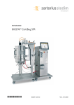
Fig. Front cover: FlexAct® COM | Abb. Titelseite: FlexAct® COM
Sartorius Stedim Biotech GmbH
Technical Documentation | Technische Dokumentation
August-Spindler-Strasse 11
D-37079 Goettingen
Germany | Deutschland
Internet: www.sartorius-stedim.com
E-mail: [email protected]
Printed in Germany on chlorine-free paper.
If you require mandatory information regarding specific properties of your FlexAct®
COM that goes beyond that which is described here, please contact us.
No part of this publication may be reprinted, reproduced or translated in any
form or by any means without the prior written permission of
Sartorius Stedim Biotech GmbH.
FlexAct® is a registered trademark of Sartorius Stedim Biotech GmbH
Gedruckt in Deutschland auf chlorfreiem Papier
Wenn Sie verbindliche Informationen zu bestimmten Eigenschaften Ihres FlexAct® COM
benötigen, welche über die hier beschriebenen hinausgehen, bitten wir um Ihre
Anfrage.
Nachdruck, Übersetzung und Vervielfältigung in jeglicher Form, auch auszugsweise,
bedürfen der schriftlichen Genehmigung der Sartorius Stedim Biotech GmbH.
FlexAct® ist eingetragenes Warenzeichen der Sartorius Stedim Biotech GmbH
2
Legal Notices
Contents
I.
II.
III.
IV.
V.
VI.
VII.
Introduction
Introduction
Abbreviations
Definitions
Operating Instructions | Intended Use
Document Structure
Explanation of Symbols
Safety Instructions
1. Setup and Equipment . . . . . . . . . . . . . . . . . . . . . . . . . . . . . . . . . . . . . . . . . . . . . . . 9
1.1 System Structure . . . . . . . . . . . . . . . . . . . . . . . . . . . . . . . . . . . . . . . . . . . . . . . 9
1.2 Setup and Structure of FlexAct® COM . . . . . . . . . . . . . . . . . . . . . . . . . . . . . . 9
1.3 Control Unit with Measurement and Control System . . . . . . . . . . . . . . . . . 10
2. Getting Started | Initial Installation . . . . . . . . . . . . . . . . . . . . . . . . . . . . . . . . . . 11
2.1 General . . . . . . . . . . . . . . . . . . . . . . . . . . . . . . . . . . . . . . . . . . . . . . . . . . . . . . . 11
2.2 Transportation . . . . . . . . . . . . . . . . . . . . . . . . . . . . . . . . . . . . . . . . . . . . . . . . . 11
2.3 Checks Prior to Setup and Connection . . . . . . . . . . . . . . . . . . . . . . . . . . . . . 11
2.4 Requirements Relating to Connections |
Energy Supply Lines on the Laboratory and Production Sides . . . . . . . . . . 12
2.5 Setup and Connection . . . . . . . . . . . . . . . . . . . . . . . . . . . . . . . . . . . . . . . . . . . 12
2.6 Connections and Energy Supply Lines (Default Values) . . . . . . . . . . . . . . . . 15
2.7 Installation of the Pressure Sensor . . . . . . . . . . . . . . . . . . . . . . . . . . . . . . . . . 15
2.8 Disposal Facilities . . . . . . . . . . . . . . . . . . . . . . . . . . . . . . . . . . . . . . . . . . . . . . . 17
2.9 Installing the Pump . . . . . . . . . . . . . . . . . . . . . . . . . . . . . . . . . . . . . . . . . . . . . 17
2.10 Installing the Filter Holder . . . . . . . . . . . . . . . . . . . . . . . . . . . . . . . . . . . . . . . 19
2.11 Installing the Scale . . . . . . . . . . . . . . . . . . . . . . . . . . . . . . . . . . . . . . . . . . . . . 19
2.12 Concluding the Installation Activities . . . . . . . . . . . . . . . . . . . . . . . . . . . . . . 20
3. Process Installation | Process Start . . . . . . . . . . . . . . . . . . . . . . . . . . . . . . . . . . . 21
3.1 General . . . . . . . . . . . . . . . . . . . . . . . . . . . . . . . . . . . . . . . . . . . . . . . . . . . . . . . 21
3.2 Safety Instructions . . . . . . . . . . . . . . . . . . . . . . . . . . . . . . . . . . . . . . . . . . . . . . 21
3.3 Installing the Magnetic Mixer Tank (Signal Cable Guide) . . . . . . . . . . . . . . . . 22
3.4 Installing the Capsules in the Filter Holder . . . . . . . . . . . . . . . . . . . . . . . . . . 22
3.5 Installing the Media Tank . . . . . . . . . . . . . . . . . . . . . . . . . . . . . . . . . . . . . . . . 24
3.6 Completing the Process Setup Steps . . . . . . . . . . . . . . . . . . . . . . . . . . . . . . . 26
4. Running the Process with FlexAct® COM . . . . . . . . . . . . . . . . . . . . . . . . . . . . . . 27
4.1 General . . . . . . . . . . . . . . . . . . . . . . . . . . . . . . . . . . . . . . . . . . . . . . . . . . . . . . . 27
Principles of Operation . . . . . . . . . . . . . . . . . . . . . . . . . . . . . . . . . . . . . . . . . . 27
4.2 Process Start . . . . . . . . . . . . . . . . . . . . . . . . . . . . . . . . . . . . . . . . . . . . . . . . . . . 27
4.3 Start Screen | Process Control . . . . . . . . . . . . . . . . . . . . . . . . . . . . . . . . . . . . 27
“Main” Main Function . . . . . . . . . . . . . . . . . . . . . . . . . . . . . . . . . . . . . . . . . . . 27
“Trend” Main Function . . . . . . . . . . . . . . . . . . . . . . . . . . . . . . . . . . . . . . . . . . 27
“Settings” System Configuration . . . . . . . . . . . . . . . . . . . . . . . . . . . . . . . . . . 27
Calibrating the Sensors . . . . . . . . . . . . . . . . . . . . . . . . . . . . . . . . . . . . . . . . . . 27
4.4 Other Functions . . . . . . . . . . . . . . . . . . . . . . . . . . . . . . . . . . . . . . . . . . . . . . . . 27
5. Ending the Process . . . . . . . . . . . . . . . . . . . . . . . . . . . . . . . . . . . . . . . . . . . . . . . . . . 28
5.1 End of Process . . . . . . . . . . . . . . . . . . . . . . . . . . . . . . . . . . . . . . . . . . . . . . . . . 28
5.2 Concluding Processes, Cleaning and Maintenance . . . . . . . . . . . . . . . . . . . . 28
Optional Features, Special Accessories . . . . . . . . . . . . . . . . . . . . . . . . . . . . . 28
General Notes . . . . . . . . . . . . . . . . . . . . . . . . . . . . . . . . . . . . . . . . . . . . . . . . . . 28
Contents
3
Introduction
I. Introduction
Introduction
FlexAct® COM is a work platform that links together a variety of biomanufacturing
tasks. A pump and a filter holder can be used for transferring and filtering media.
A microcomputer and touch-screen driven operation enable the user to document
and display process-relevant data.
This document describes different models and equipment of FlexAct® COM that were
available at the time of its creation. The equipment supplied with a device does not
necessarily cover every possible type of equipment; some may differ from the
description while others may contain additional equipment. The descriptions for the
fittings can differ from the ones in the related P&I diagram and the equipment list
because these documents are each adapted to the customer’s specific requirements.
Documentation on customer-specific designs and equipment can be separately
supplied or are available on request.
Sartorius Stedim Biotech GmbH
Customer Service
August-Spindler-Strasse 11
37079 Goettingen, Germany
Phone +49.551.308.3318
Fax +49.551.308.3755
www.sartorius-stedim.com
II. Abbreviations
4
Introduction
BI
BP
COM
DCU FlexAct®
l/L
P&I Diagram
SSB
VI
CDS
MP
VR
CH
Basic Issue
Buffer Preparation
Central Operating Module
Sartorius Stedim Measurement and Control System
Liter
Piping & Instrumentation Diagram
Sartorius Stedim Biotech
Virus Inactivation
Configurable Disposable Solution
Media Preparation
Virus Removal
Cell Harvest
III. Definitions
IV. Operating Instructions|
Intended Use
FlexAct® COM
FlexAct® COM ready-to-connect system with
- Trolley,
- DCU microbox
- Touch-screen
- Pump
- Filter holder | Drip tray
- Pump head supporting plate
and
- PT100 temperature sensor
Initial Installation |
Getting Started
Description of all steps required to set up FlexAct® COM after
its delivery or whenever its location is moved.
Once assembly | installation of attached parts and the pump
is completed, the steps for initial installation are concluded
by connecting FlexAct® COM to the power supply in the
laboratory or belonging to the process.
Process Installation |
Process Start
Description of all steps required to start a process.
Process Capability
Time at which the actual process, for example buffer
preparation or virus inactivation, can be started. Process
capability is reached when the initial operations are set
up to completion.
FlexAct® COM may only be used with equipment and under operating conditions
described in the present equipment documentation. FlexAct® COM is basically a work
platform. It accommodates all accessory parts necessary for transferring media within
biotechnological applications.
Users must be qualified to handle the system and the process-relevant media and be
aware of the hazards potentially associated with the process. Some processes may
require that FlexAct® or the workplace be equipped with additional safety features or
that precautions be otherwise taken to protect personnel and working environment.
This document does not go into further detail about such circumstances, legislation
or regulations that may otherwise bind the operator. Safety and warning instructions
given in this document only apply to the devices and supplement the rules and
regulations the operator stipulates at the workplace for the respective process.
© Sartorius Stedim Biotech GmbH. No guarantee is assumed for the information provided. Sartorius
reserves the right to make technical changes to the equipment or changes to this document without any
prior notice. No part of this document may be changed, or reproduced, nor is any other use permitted
without obtaining prior written permission.
Introduction
5
V. Document Structure
This document is structured according to the following outline:
Chapter
Contents
Introduction Notes on this document, operating and safety instructions
VI. Explanation of Symbols
1.
Information about setup and equipment of FlexAct® COM
2.
Delivery, setup and connection | Initial installation in the laboratory |
production process:
– Workplace requirements, required installation and energy supplies
– Steps to make the equipment operable
3.
Process installation | Start of the process running on FlexAct® COM
(example process: buffer preparation):
– Installation of the Palletank for storage with capsules
– Installation of the LevMixer Palletank with sensors
– Instating process capability
4.
Running a process with FlexAct® COM:
– Starting the process
– Start screen
– Process control (t Operating instructions manual for DCU FlexAct®)
– Calibrating the sensors
5.
Concluding the process with FlexAct® COM
(example process: buffer preparation):
– End of process
– Deinstallation of LevMixer®, Palletank®, Capsules, Palletank®
for storage
– Integrity test at or of the capsules
6.
Appendix containing Decontamination Declaration, CE Declaration,
example process(es), operating instructions manuals for the FlexAct®
components DCU FlexAct®, operating instructions manual for
peripheral devices, etc.
The “Warning” symbol and this formatting indicate hazards that can be
expected with a high probability and can lead to severe injuries.
The “Caution” symbol and this formatting indicate hazards that can occur and
can lead to severe injuries if the notes and instructions are not observed.
This warning indicates risks that can lead to material damage.
Instructions and notes labeled with this symbol indicate steps that must be
performed with particular care, or point to other especially important aspects
to be observed.
6
Introduction
y
The box indicates other important information.
1., 2., ...
Numbered paragraphs indicate steps that should be performed consecutively in the
order listed.
t
This symbol points to information referenced in another section.
VII. Safety Instructions
Organizational measures on the part of the operator:
y The operator must point out the hazards to which personnel and the working
environment may be subject during the process, must provide the suitable safety
equipment, and must publish the stipulated safety requirements.
y Only operating personnel qualified to run the process may be employed for
working with FlexAct® COM; they must be aware of potential hazards, and be
thoroughly familiar with the handling of all devices.
y Non-authorized persons must be prohibited from working on FlexAct® COM.
If hazards are associated with the process (e.g. due to process-relevant media),
the workplace must be labeled with suitable danger symbols, e.g. “BIOHAZARD”
and it should be possible to cordon it off or quarantine it if the circumstances
require.
y The workplace must be suitable for the process, e.g. resistant to acids, bases or
media and must be easy to clean, decontaminate and disinfect if contaminated.
y In general, operators must wear suitable personal protective equipment
(e.g. work clothes, gloves, safety goggles as well as a facemask if appropriate).
Workplace Setup
Workplace and supply connections in the laboratory | production facility must meet
the requirements stipulated in the equipment specifications. All intended equipment
must be complete and free of defects and flaws.
Risk of injury if energy supply lines are inadvertently activated
(e.g. power supply, water, gas inlet supplies).
Energy supply lines must be blocked or secured against inadvertent startup
whenever you:
Connect or disconnect laboratory connections or connections on the production
side.
Want to disassemble peripheral installations.
When transporting or moving FlexAct® COM, be fully aware that you are moving
equipment with an extremely high weight.
Ensure that all necessary measures are taken (e.g. warning information,
barriers, safety gear, etc.) to prevent any danger of crushing or roll-over, and
thereby the risk of injury to persons.
When assembling the PT 100 temperature sensor, make sure that the bag is
filled and not to damage the sensor channel when inserting the sensor.
Pierced or damaged sensor channels will make the bag unusable!
1. Ensure that all supply media on the laboratory or production sides , e.g. water,
supply voltage etc., match the specifications t “P&I Diagram”.
2. The workplace must be able to carry FlexAct® COM with all equipment and the
intended peripheral devices. Observe the weight and the space requirements
t "Setup and Connection“. Use suitable transportation aids when transporting
FlexAct® COM to the place of installation and | or changing its location.
3. Secure all laboratory connections | connections on the production side carefully.
Introduction
7
4. Use only the equipment provided or released for the device. Never make any
technical modifications, unless Sartorius Stedim Biotech GmbH has expressly
confirmed that this modification does not affect safe use.
5. Loosen | remove any transport locks.
6. Check all equipment carefully for damage. Use only flawless parts.
Getting Started
All equipment must be assembled carefully and safely.
1. Before every startup, check the assembly and connections of all equipment.
Safety equipment, e.g. the overpressure | safety valves must meet the
specifications and be installed.
2. Palletanks | bags, tubing, and fittings must be leak-tight.
Persons should only stand around the equipment for carrying out necessary
work. Barricade off the hazardous area and indicate this with signs!
If applicable, ensure that the respective minimum volumes as described in the
t “Operating Instructions Manual for LevMixer®” are not undershot.
Observe the operating limits and optimal settings for the process. Only operate
FlexAct® COM using the allowable energy supplies (power supply, water or gas
supplies).
BIOHAZARD, hazards caused by media.
When working with hazardous materials, observe the pertinent safety
regulations and laws!
1. Adjust the measurement and control system in strict accordance with the
allowable performance data for the respective equipment t “Operating
Instructions Manual for DCU FlexAct®”.
2. Perform in-process monitoring as to whether the process parameters are achieved
as expected. Take precautions to ensure that defects or disruptions cannot cause
any hazards or damage.
After placing the tubing in the pump, always make sure to press the STOP key on
the pump.
This resets the system and is indispensable for proper functioning of the pump.
Safety at the End of the Process
8
Overview of the Safety Instructions
After concluding the process, all affected components of FlexAct® COM should be
disposed of, disinfected and cleaned in accordance with their use and as prescribed by
the respectively valid laws and regulations.
1. Setup and Equipment®
1. Setup and Equipment
FlexAct® COM consists of a variably configurable universal trolley
equipped with a built-in DCU FlexAct® microcomputer. Operation is driven by
a touch-screen securely mounted onto the trolley by a monitor arm.
1.1 System Structure
Sensors, like those for pH and temperature, are hooked to a sensor field on the side.
The “PT100 temperature sensor” included in the equipment supplied can also be
attached to the sensor field.
Accessory devices such as the BioWelder®, BioSealer® can be plugged into the multiple
socket outlet built into the rear panel.
A filter holder and a pump head supporting plate are standard components
of FlexAct® COM and can be connected to the trolley at a variety of positions.
Differently sized filters | capsules can be installed in the filter holder.
The pump head supporting plate is designed to stabilize the pump.
1.2 Setup and Structure of
FlexAct® COM
(Example Process
“Buffer Preparation”)
9
8
11
For further types of processes|applications, the setup and structure of
FlexAct® COM could differ from the example process "Buffer Preparation".
For details, please refer to the appendix entitled t “Example Processes”.
10
7
5
4
13
1
2
6
3
14
12
Fig. 1-1: Overview of FlexAct® COM
Equipment supplied with FlexAct® COM
(1) COM (trolley)
(2) Main switch | Emergency shutoff switch
(3) Keypad | touch-screen
(4) Pump
(5) Pump head supporting plate
(6) Filter holder | capsules
(7) PT100 temperature sensor kit
Accessory Devices
(8) Scale
(9) Keypad scale
Recommended Accessories (for Running the Process)
(10) LevMixer® with Palletank (“buffer preparation“)
(11) Powder bag
(12) Palletank (“Storage“)
(13) Sartocheck®
(14) BioWelder® | BioSealer®
System Setup
9
1.3 Control Unit with Measurement
and Control System
Hardware
The “DCU FlexAct®” measurement and control system is run by a microprocessor
specially designed and developed for the FlexAct® family. The unit is operated directly
on the touch-screen.
y Process controls as described in the t “Master Components List”.
y The t “Operating Instructions Manual for DCU FlexAct®” contains detailed
information about the hardware.
Peripheral Connections
FlexAct® COM can be ported to the following external devices:
y Scale
The t “Operating Instructions Manual for the Scale“ contains detailed
information about scales pre-configured for FlexAct® COM.
y pH Sensor (e. g. installed in the Flexel® bag for LevMixer®)
The t “Operating Instructions Manual for the Flexel® bag for LevMixer®“ contain
safety instructions and detailed installation instructions.
y PT100 temperature sensor
The t “Operating Instructions Manual for the PT100 Temperature Sensor“
contains detailed information on the temperature sensor.
y External|alternative scale signal
If needed, please contact your local SSB service technician.
He would be happy to answer your questions!
y Ethernet port (multi-function)
Software updates,
Data transfer via MFCS
If needed, please contact your local SSB service technician.
He would be happy to answer your questions!
y Sartocheck® (power connection only)
t “Operating Instructions Manual for Sartocheck®”
y BioWelder® (power connection only)
t “Operating Instructions Manual for Sartocheck®”
y BioSealer® (power connection only)
t “Operating Instructions Manual for Sartocheck®”
Software
y The t “Operating Instructions Manual for the DCU FlexAct®” contains detailed
information about the software.
10
System Setup
2. Getting Started | Initial Installation
2. Getting Started | Initial Installation
2.1 General
Sartorius Stedim Biotech GmbH recommends that our authorized service technicians
carry out the initial installation FlexAct® COM at the operator’s workplace.
The following information summarizes the key aspects to be observed during the
setup. They also apply to the re-installation at the workplace after a change of
location or after temporary suspensions from use.
2.2 Transportation
y Transportation equipment must be available that can sufficiently bear the load.
Transport routes and the potentially required elevator must be sufficiently
dimensioned and have the weight-bearing capacity needed to handle FlexAct®
COM and the transportation equipment without any hazards.
y Only use personnel qualified to transport FlexAct® COM. Prevent harm to any
uninvolved persons. Transport locks may not be removed until the system has
arrived at the place of installation.
Before you move the location of FlexAct® COM to another place within the
production facilities, you must perform the following steps:
y Unplug all connections (refer to t “Chapter 5, Ending the Process”)
y Push the pump all the way back underneath the FlexAct® COM working counter.
y De-install the pump head supporting plate
y Remove the filter holder
2.3 Checks Prior to Setup
and Connection
Completeness of the supplies
Check that the delivery is complete by comparing it against your order.
Check all components carefully for any damage.
y All required attached parts, tubing and|or cables that do not meet the
specifications of Sartorius Stedim Biotech GmbH may not be used.
y If damage that occurred during transport is noticed during startup, please notify
the hauler and have the damage documented for the record.
Report the transport damage, missing parts or malfunctions to your Sartorius
Stedim Systems GmbH representative.
Getting Started | Initial Installation
11
2.4 Requirements Relating to
Connections | Energy Supply
Lines on the Laboratory and
Production Sides
Danger of personal injury can arise if any power connections and supplies on the
laboratory or production sides are not correctly secured against unallowable
fluctuations and malfunctions and if the personnel are exposed to uncontrolled
energy release!
Required protection equipment that meets the safety guidelines and standards
applicable to building installations (e.g. for wet rooms), must be available and
functioning!
The following is required and | or must be ensured, among others:
y Electrical connections without impulse voltages or unallowable voltage
fluctuations (protected with ground fault circuit interrupters or equivalent fault
current protective devices or the likes).
y Prior to installation at the workplace, energy and supply connections must be
prepared and easily accessible; the energy sources must be dimensioned in
accordance with the specifications for the respective FlexAct® COM and be free
of qualitative flaws.
Information on this subject can be found in the t “Appendix” for FlexAct® COM.
2.5 Setup and Connection
y FlexAct® COM can be set up at any suitable laboratory or production workplace.
The place of installation must meet the requirements set down in the following
Chapter t “Dimensions, Connecting Power | Energy Supply Lines”!
The place of installation must have a weight-bearing capacity that can withstand having FlexAct® set up there. When dimensioning accordingly, it is imperative to observe that the maximal potential weight of the respective media and
their containers has to be added to the intrinsic weight of the respective
FlexAct® COM!
y The surface at the workplace must be able to hold the weight of the completely
filled FlexAct® COM. The total weight of the FlexAct® COM depends on the
customer’s specific equipment, the connected devices and the weight of the
medium at maximum filling.
The working area for FlexAct® COM must be set up separately from the other
generally accessible areas.
Ensure that only authorized persons have access to FlexAct® COM.
y Setup surface and room height must be dimensioned in such a way that makes
FlexAct® COM easily accessible for in-process operation, maintenance and service
work. The space requirements also depend on the peripheral devices to be
connected. An overview of the equipment dimensions is given under
t “Dimensions, Connecting Power | Energy Supply Lines”.
12
Getting Started | Initial Installation
y To set up FlexAct® COM, you must perform the following steps:
1. First select a place for the pump.
The pump can be positioned either on the left (Fig. 2-1) or the right (Fig. 2-2)
side of FlexAct® COM.
The ergonomical setup shown in Fig. 2-1 is recommended.
When setting up FlexAct® COM as shown in Fig. 2-2 do so as if looking at a mirror
image. Any possible differences will be explicitly designated in these operating
instructions.
Fig. 2-1: FlexAct® COM with left-sided pump
Fig. 2-2: FlexAct® COM with right-sided pump
2. Leave enough distance to the wall for energy and supply connections. FlexAct®
COM and any equipment to be operated manually must be easily accessible.
3. Check to make sure that all power connections and supplies on the laboratory
or production sides are correctly preinstalled, configured and ready-to-operate
t “Chapter 2.4 Dimensions, Connecting Power | Energy supply lines” and | or
t “P&I Diagram”:
– Supply voltage,
– Cooling water connection and return flow in the laboratory,
– Inlet air connection and | or the desired gas supply as well as any exhaust air
fittings in the laboratory.
4. Connect all energy supply lines. The respective connections are labeled on
FlexAct® COM.
5. Leave enough distance to the wall for energy and supply connections. FlexAct®
COM and any equipment to be operated manually must be easily accessible.
Getting Started | Initial Installation
13
Danger of functional problems and operational malfunctions or defects through
contaminated cooling water or contaminated air and | or gases.
Cooling water, compressed air and | or gases must be free of residual corrosion,
deposits or the likes, deriving from the laboratory supply lines.
If necessary, the suitable prefilters should be installed.
The working area for FlexAct® COM must be set up separately from the other
generally accessible areas.
Ensure that only authorized persons have access to FlexAct® COM.
Ensure that all energy and supply connections are set up in accordance with the
specifications for FlexAct® COM and correctly dimensioned.
Specific information on the delivered device can be found in its installation plan,
and | or in the P&I Diagram.
Safety equipment, e.g. emergency shut-off, must be easily accessible.
D
D
W
Fig. 2-3: FlexAct® COM footprint
FlexAct® COM with pump
H – Height [mm|inch]
W– Width [mm|inch]
D – Depth [mm|inch]
Weight [kg|lb]
14
Getting Started | Initial Installation
1.500|59.06
1.410|55.51
795|31.3
160|352.74
2.6 Connections and Energy
Supply Lines (Default Values)
2.7 Installation
of the Pressure Sensor
Connections for
Values
Power Requirements | 110 V,.60 Hz|15 A or
Protective grounding 230 V, 50 Hz|16 A
conductor(s)
Special Notes
FlexAct® COM is factory-configured
to the country-specific power
outlets and electrical current.
If you need configuration to fit the
country-specific power outlets, this
should be done by your local SSB
service technician.
The position of the pressure sensor is variable and depents upon the application.
For details please refer to the different process examples!
y To install the pressure sensor, you must perform the following steps:
1. Take the pressure sensor outoff the packing and remove the packing.
2. Rotate the transport protection to the left and remove it from the pressure sensor.
3. Crack the central plate of the transport protection and remove it.
4. Install the transport protection on the pressure sensor by a clockwise truning.
Fix this position manually.
y To install the pressure sensor on the pressure sensor carriage you must perform
the following steps:
1. Remove the sleeve nut from the sensor-holder.
2. Install the IDOME tube-holder.
Getting Started | Initial Installation
15
3. Install the sleeve nut Setzen and tighten it light.
4. Remove the protecting cap from the sensor.
5. Crack the central plate of the protecting cap with a finger and remove it.
6. Install the sensor with ist pre-mounted tubes in the sensor-holder.
Handle the clamps with care. These clamps can be cracked very easily!
7. Close the clamps.
8. After closing the clamps tighten the ring:
Turn the ring until it clicks into place.
9.
16
Getting Started | Initial Installation
Close the tube-clamps.
10. Connect the pressure sensor and the related port with the corresponding
sensor-cable.
2.8 Disposal Facilities
Risk of infection from biologically contaminated exhaust air or waste water!
Observe the relevant safety regulations. Set up the workplace to accommodate
the requirements of the process. Set up and connect the appropriate equipment
for collection and treatment of contaminated exhaust air or waste water!
2.9 Installing the Pump
To install the pump in accordance with the t “Operating Instructions Manual for
the “Pump“ in FlexAct® COM, you must perform the following steps:
1. Install the pump head supporting plate on the lower mounting level
of FlexAct® COM.
When moving the pump, remember to take its heavy weight into account.
Ensure that all necessary measures are taken (e.g. warning information, safety
gear, etc.) to prevent any risk of injury to persons.
2. Remove the pump from the packaging.
3. Place the pump on the middle shelf of FlexAct® COM
Position the pump so that the pump head stands on the supporting plate
intended for the pump head.
This ensures that you place the (media) tubing correctly!
Sensor field
Pump
Pump head supporting plate
Fig. 2-4: Pump assembly
Getting Started | Initial Installation
17
4. Plug the signal cable for the scales into the “Scale” port (left
figure shows the sensor field of the FlexAct®, “Revision 2”).
5. Using the coupling, connect the pump’s power supply to FlexAct® COM.
6. Press the switch-on button on the back panel of the pump to position “I”.
18
Getting Started | Initial Installation
2.10 Installing the Filter Holder
To install the filter holder on FlexAct® COM, you must perform the following steps:
1. Install the filter holder on the upper assembly level of FlexAct® COM.
When moving the filter holder, remember to take its heavy weight into account.
Ensure that all necessary measures are taken (e.g. warning information, safety
gear, etc.) to prevent any risk of injury to persons.
2. Adjust the upper capsule holder to the level of the upper working counter of
FlexAct® COM so as to enable the most ergonomic working style.
Make sure that both brackets are mounted on their respective capsules holders.
2.11 Installing the Scale
y To install the scale for a process to be carried out with FlexAct® COM, you must
perform the following steps:
1. Set up the scale as described in the t “Operating Instructions Manual for the
Scale”.
2. Plug the scale’s signal cable equipped with the M12 male connector into the
female connector labeled “SCALE” in the connector panel on FlexAct® COM.
If the M12 port mentioned above is not available, for example, if another scale is
connected, please contact your local SSB service technician.
Getting Started | Initial Installation
19
2.12 Concluding the
Installation Activities
The preparatory installation activities are concluded once
y The pump head supporting plate has been mounted,
y The pump is installed,
y The filter holder has been adjusted and mounted
and
y The scale is connected.
FlexAct® COM is now ready for the following Process Installation | Process Start.
20
Getting Started | Initial Installation
3. Process Installation | Process Start
3. Process Installation | Process Start
3.1 General
Chapter 3 describes the Process Installation | Process Start of FlexAct® COM.
The following illustrates all steps necessary for getting started “mechanically” using
“buffer preparation” as an example. The example represents a typical process
installation for FlexAct® COM.
The chronological sequence of events for this type of process is described in the
Appendix entitled t “Example Process Buffer Preparation”.
For further types of processes|applications, the Process Installation|Process
Start of FlexAct® COM could differ from the example process "Buffer
Preparation". For details, please refer to the appendix entitled t “Example
Processes”.
Documents relating to customer-specific equipment will be included with the device
or sent to you under separate cover. Please contact Sartorius Stedim Biotech if you
require additional information to go with these.
3.2 Safety Precautions
Risk of injury for persons standing near FlexAct®‚ COM!
Improperly mounted fittings, e.g. for water, gases and media and buffer
transportation, can become loosened inadvertently!
After retrofitting and maintenance or servicing, always check the connection
to energy supply lines and make sure that the safety equipment is set up and
functioning properly.
FlexAct® COM, DCU FlexAct®‚ PT100 temperature sensor and scale are designed
to match to each other.
To prevent the danger of functional problems and operational malfunctions or
defects caused by improper installation, it is recommended that SSB Service
personnel carry out initial installation.
After being instructed by SSB Service personnel and following the steps
described herein, every user will be enabled to carry out the transport and
installation activities themselves.
Carry out the steps for installing FlexAct® COM in the process | production chain
in the following order to ensure an optimum process control.
Process Installation | Process Start
21
3.3 Installing the Magnetic Mixer Tank
(Signal Cable Guide)
y Plug all signal cables into the corresponding ports on the sensor panel on
FlexAct® COM.
3.4 Installing the Capsules
in the Filter Holder
y The filter holder can be adjusted to fit all different capsule sizes.
y The bracket for capsules with a small diameter (MidiCaps) should be mounted
at the back position. The bracket for capsules with a large diameter (MaxiCaps) at
the front position.
You can adapt the different capsule heights by shifting the lower capsule holder:
1. Pre-mount the brackets on the capsule holder as described above.
2. Position the lower capsule holder to fit the capsule height as described above.
22
Process Installation | Process Start
Bracket position for MaxiCap
Capsule holder for MaxiCap
Bracket position for MidiCap
Capsule holder for MidiCap
To install capsules in the filter holder, you must perform the following steps:
During installation, pay attention to the tube guide.
The tubing should not be subject to any tension, kinking or crushing.
Otherwise, the flow of media may be inadvertently impaired.
1. Open both brackets.
2. Position the capsules so that the upper edge of the capsule lies against the upper
capsule holder.
3. Close the brackets.
Process Installation | Process Start
23
3.5 Installing the Media Tank
y To install the outlet hose of the media tank to the FlexAct® COM (illustrated here
using the LevMixer® tank as an example), you must perform the following steps:
1. Select the outlet hose of the media tank.
2. Run the tubing near the filter holder.
At the end of the tubing attach the clip and remove the screen.
3. Place the gasket in the flange of the capsule
(installed on the filter holder).
4. Close the clamp connection and make sure that this connection is seated
properly.
24
Process Installation | Process Start
5. Guide the media tubing backwards in the direction of the pump and media tank.
6. In doing so, lay the tubing over the tubing baffle.
Pay attention during this process that the radial transitions are gentle and avoid
crushing the tubing.
7. Open the pump housing as depicted in the
t “Operating Instructions Manual for the Pump“.
8. Remove the two tube clips.
9. Position the media tubing in the pump as depicted in the t “Operating
Instructions Manual for the Pump“.
10. Install the two tube clips, without crushing the tubing.
11. Close the pump head protection.
Press the “STOP” button on the pump keypad.
This “Reset” is indispensable for the process capability of the system.
12. When placing the media tubing, make sure that there is no kinking and crushing.
If necessary, vary the position of the tubing holder to guarantee a secure seat of
the tubing on the FlexAct® COM.
Process Installation | Process Start
25
3.6 Completing the Process Setup Steps
Once FlexAct® COM has been set up as described in Chapter 3 Process Installation |
Process Start, the System is process-ready | ready for “buffer preparation” as
illustrated in the example in the figure below.
Fig. 3-1: Complete process setup of FlexAct® COM (example process “buffer preparation”)
All power lines must be connected and switched on.
The clips on all tubing supplying the medium must be open.
y To conclude the startup procedure, you must perform the following steps:
26
Process Installation | Process Start
4. Running the Process
with FlexAct® COM
4. Running the Process
with FlexAct® COM
4.1 General
Principles of Operation
The basics of operating the microbox are described in the
t „Operating Instructions Manual for DCU FlexAct®”.
4.2 Process Start
Start operation of FlexAct® COM using the touch-screen as described in the
t “Operating Instructions Manual for DCU FlexAct®”.
Switch on the main switch.
4.3 Start Screen |
Process Control
The process control and display of the process parameters are touch-screen-driven
as described in the t “Operating Instructions Manual for DCU FlexAct®”.
The following main functions are available:
“Main” Main Function
The “Main” main function on FlexAct® COM is described in the
t “Operating Instructions Manual for DCU FlexAct®”.
"Trend” Main Function
The “Trend” main function on FlexAct® COM is described in the
t “Operating Instructions Manual for DCU FlexAct®”.
“Settings” System Configuration
The “Settings” system configuration on FlexAct® COM is described in the
t “Operating Instructions Manual for DCU FlexAct®”.
“Calibration” Sensor Calibration
The “Calibration” main function on FlexAct® COM is described in the
t “Operating Instructions Manual for DCU FlexAct®”.
4.4 Other Functions
The other functions such as alarms and messages, troubleshooting, password system,
etc. are described in the t “Operating Instructions Manual for DCU FlexAct®” and in
the t “Calibration Handbook”.
Running the Process with FlexAct® COM
27
5. Ending the Process
5. Ending the Process
For further types of processes|applications, the Ending of the Process could
differ from the example process "Buffer Preparation".
For details, please refer to the appendix entitled t “Example Processes”.
5.1 End of Process
Release any pressure in the system by opening the upper vent valve on the
capsule!
y Close all tube clips.
y Use the BioSealer® to separate the tubing line of the Palletank from the capsule
as described in the t “Operating Instructions Manual for the BioSealer®”
5.2 Concluding Processes,
Cleaning and Maintenance
To end a process, you must perform the following steps
y After concluding a process, remove filters and tubing from COM and dispose of
all product-contact components as described in t “Chapter 6.8 Instructions for
Disposal”!
y In the case of slight contamination, it suffices to clean COM with a wet cloth.
y You can mechanically clean the metal parts or using a mild detergent or alcohol.
Make that you do not cause any scratching.
y Clean the PT100 according to the manufacturer's instructions.
y Only ever clean the touch-screen display with a dry cloth.
Optional Features, Special Accessories
General Notes
This section contains notes regarding components and peripheral devices that are
not supplied as standard equipment with FlexAct® t “Master Components List and
P&I Diagram”. Documents will be supplemented depending on their availability or
compiled for the customer-specific version of FlexAct® COM as needed.
Please contact your supplier or Sartorius Stedim Biotech GmbH directly if your
FlexAct® COM is equipped with components and peripheral devices that are not
described in this manual and that you have not received a separate document for.
Sartorius Stedim Systems GmbH
Service Hotline
Schwarzenberger Weg 73–79
34212 Melsungen, Germany
Phone +49.5661.716677
Fax +49.5661.713250
www.sartorius-stedim.com
28
Ending the Process
Inhalt
I.
II.
III.
IV.
V.
VI.
VII.
Einleitung
Einführung
Abkürzungsverzeichnis
Begriffsdefinitionen
Verwendungshinweise|Bestimmungsgemäße Verwendung
Dokumentationsaufbau
Zeichenerklärung
Sicherheitshinweise
1. Aufbau und Ausstattung des FlexAct® COM . . . . . . . . . . . . . . . . . . . . . . . . . . . . 35
1.1 Struktur des Systems . . . . . . . . . . . . . . . . . . . . . . . . . . . . . . . . . . . . . . . . . . . . 35
1.2 Aufbau und Struktur des FlexAct® COM . . . . . . . . . . . . . . . . . . . . . . . . . . . . 35
1.3 Kontrolleinheit mit Mess- und Regelsystem . . . . . . . . . . . . . . . . . . . . . . . . . 36
2. Inbetriebnahme | Erstinstallation . . . . . . . . . . . . . . . . . . . . . . . . . . . . . . . . . . . . . 37
2.1 Allgemein . . . . . . . . . . . . . . . . . . . . . . . . . . . . . . . . . . . . . . . . . . . . . . . . . . . . . 37
2.2 Transport . . . . . . . . . . . . . . . . . . . . . . . . . . . . . . . . . . . . . . . . . . . . . . . . . . . . . . 37
2.3 Kontrollen vor Aufstellung und Anschluss . . . . . . . . . . . . . . . . . . . . . . . . . . 37
2.4 Anforderungen an labor- und
produktionsseitige Anschlüsse und Energien . . . . . . . . . . . . . . . . . . . . . . . . 38
2.5 Aufstellung und Anschluss . . . . . . . . . . . . . . . . . . . . . . . . . . . . . . . . . . . . . . . 38
2.6 Anschlüsse und Energien (Standardwerte) . . . . . . . . . . . . . . . . . . . . . . . . . . 41
2.7 Installation des Druckaufnehmers für das deutsche Inhaltsverzeichnis . . . 41
2.8 Entsorgungseinrichtungen . . . . . . . . . . . . . . . . . . . . . . . . . . . . . . . . . . . . . . . 43
2.9 Installation der Pumpe . . . . . . . . . . . . . . . . . . . . . . . . . . . . . . . . . . . . . . . . . . 43
2.10 Installation des Filterhalters . . . . . . . . . . . . . . . . . . . . . . . . . . . . . . . . . . . . . . 45
2.11 Installation der Waage . . . . . . . . . . . . . . . . . . . . . . . . . . . . . . . . . . . . . . . . . . 45
2.12 Abschluss der Installationstätigkeiten . . . . . . . . . . . . . . . . . . . . . . . . . . . . . . 46
3. Prozess-Installation | Prozess-Start . . . . . . . . . . . . . . . . . . . . . . . . . . . . . . . . . . . 47
3.1 Allgemein . . . . . . . . . . . . . . . . . . . . . . . . . . . . . . . . . . . . . . . . . . . . . . . . . . . . . 47
3.2 Sicherheitshinweise . . . . . . . . . . . . . . . . . . . . . . . . . . . . . . . . . . . . . . . . . . . . . 47
3.3 Installation Magnetic Mixer Tank (Signal-Führung) . . . . . . . . . . . . . . . . . . 48
3.4 Installation Capsule am Filterhalter . . . . . . . . . . . . . . . . . . . . . . . . . . . . . . . . 48
3.5 Installation Medien-Tank . . . . . . . . . . . . . . . . . . . . . . . . . . . . . . . . . . . . . . . . 50
3.6 Abschluss der Prozess-Inbetriebnahme-Tätigkeiten . . . . . . . . . . . . . . . . . . . 52
4. Prozess-Durchführung mit FlexAct® COM . . . . . . . . . . . . . . . . . . . . . . . . . . . . . 53
4.1 Allgemein . . . . . . . . . . . . . . . . . . . . . . . . . . . . . . . . . . . . . . . . . . . . . . . . . . . . . 53
Grundlagen der Bedienung . . . . . . . . . . . . . . . . . . . . . . . . . . . . . . . . . . . . . . . 53
4.2 Prozess-Start . . . . . . . . . . . . . . . . . . . . . . . . . . . . . . . . . . . . . . . . . . . . . . . . . . 53
4.3 Startbildschirm | Prozess-Steuerung . . . . . . . . . . . . . . . . . . . . . . . . . . . . . . . 53
Hauptfunktion „Main“ . . . . . . . . . . . . . . . . . . . . . . . . . . . . . . . . . . . . . . . . . . . 53
Hauptfunktion „Trend“ . . . . . . . . . . . . . . . . . . . . . . . . . . . . . . . . . . . . . . . . . . 53
Systemeinstellungen „Settings“ . . . . . . . . . . . . . . . . . . . . . . . . . . . . . . . . . . . 53
Kalibrierung der Sensoren „Calibration“ . . . . . . . . . . . . . . . . . . . . . . . . . . . . 53
4.4 Sonstiges . . . . . . . . . . . . . . . . . . . . . . . . . . . . . . . . . . . . . . . . . . . . . . . . . . . . . . 35
5. Beendigung des Prozesses . . . . . . . . . . . . . . . . . . . . . . . . . . . . . . . . . . . . . . . . . . . 54
5.1 Prozess-Ende . . . . . . . . . . . . . . . . . . . . . . . . . . . . . . . . . . . . . . . . . . . . . . . . . . 54
5.2 Abschluss von Prozessen, Reinigung und Wartung . . . . . . . . . . . . . . . . . . . .54
Ausstattungsoptionen, Spezielles Zubehör . . . . . . . . . . . . . . . . . . . . . . . . . . 54
Allgemeine Hinweise . . . . . . . . . . . . . . . . . . . . . . . . . . . . . . . . . . . . . . . . . . . . 54
Inhalt
29
Einleitung
I. Einführung
Einleitung
Der FlexAct® COM ist eine Arbeitsplattform, welche verschiedene Arbeitsabläufe der
biotechnologischen Produktion miteinander verknüpft. Mit einer Pumpe und einem
Filterhalter können Medien transferiert und filtriert werden. Ein Touch Panel sowie
ein Mikrocomputer ermöglichen die Erfassung und Visualisierung von prozessrelevanten Daten.
Diese Dokumentation beschreibt Ausführungen und Ausrüstungen des FlexAct® COM,
wie sie bei Erstellung bekannt waren. Der Lieferumfang eines Gerätes muss nicht alle
möglichen Ausrüstungen umfassen, diese können sich von der Beschreibung unterscheiden oder es können zusätzliche Ausrüstungen enthalten sein. Die Bezeichnungen
von Armaturen können von denen im zugehörigen P&I Diagram und der Ausstattungsliste abweichen, da diese Unterlagen jeweils kundenspezifisch angepasst
werden. Unterlagen zu kundenspezifischen Ausführungen und Ausrüstungen können
separat geliefert werden oder sind auf Anfrage erhältlich.
Sartorius Stedim Biotech GmbH
Customer Service
August-Spindler-Str. 11
D-37079 Göttingen
Tel.: +49 (0) 551 –308 36 82
Fax: +49 (0) 551 –308 37 55
Internet: www.sartorius-stedim.com
II. Abkürzungsverzeichnis
30
Einleitung
BI
BP
COM
DCU FlexAct®
l/L
P&I Diagram
SSB
VI
CDS
MP
VR
CH
Basic Issue|Erstausgabe
Buffer Preparation
Central Operating Module
Sartorius Stedim Mess- und Regelsystem
Liter
Piping & Instrumentation Diagram
Sartorius Stedim Biotech
Virus Inactivation
Configurable Disposable Solution
Media Preparation
Virus Removal
Cell Harvest
III. Begriffsdefinitionen
IV. Verwendungshinweise|
Bestimmungsgemäße
Verwendung
FlexAct® COM
Komplettes System FlexAct® COM mit
- Wagen|Trolley,
- DCU-Steuereinheit
- Touch-Panel
- Pumpe
- Filterhalter | Abtropfwanne
- Pumpenkopf-Stützblech
und
- PT100 Temperatursensor
Erstinstallation |
Aufstellen des
Inbetriebnahme
Beschreibung aller erforderlichen Tätigkeiten, welche zum
FlexAct® COM – nach dessen Anlieferung oder Standort
wechsel – erforderlich sind.
Nach Montage|Installation der Anbauteile und der Pumpe
werden die Tätigkeiten der Erstinstallation mit dem Verbinden
des FlexAct® COM an die labor- oder prozessseitige Stromversorgung abgeschlossen.
Prozess-Installation |
Prozess-Start
Beschreibung aller erforderlichen Tätigkeiten, welche für den
Start eines Prozesses erforderlich sind.
Prozessfähigkeit
Zeitpunkt zu welchem der eigentliche Prozess, wie zum
Beispiel eine Buffer-Preparation oder Virus Inactivation,
gestartet werden kann. Die Prozessfähigkeit ist mit Abschluss
der Inbetriebnahme erreicht.
Der FlexAct® COM darf nur mit Ausstattungen und unter Betriebsbedingungen
eingesetzt werden, die in dieser Gerätedokumentation beschrieben sind.
Generell ist FlexAct® COM eine Arbeitsplattform. Auf dieser können alle notwendigen
Zubehörteile platziert werden, welche für den Transfer von Medien innerhalb einer
biotechnologischen Anwendung erforderlich sind.
Benutzer müssen für den Umgang mit dem Gerät und den prozessrelevanten Medien
qualifiziert sein und die Gefahren kennen, die vom vorgesehenen Prozess ausgehen
können. Die Prozesse können es erforderlich machen, das Gerät oder den Arbeitsplatz
mit zusätzlichen Sicherheitsausrüstungen auszustatten oder sonstige Vorkehrungen
zum Schutz von Personal und Arbeitsumfeld zu treffen. Die Dokumentation geht
nicht näher auf solche Umstände, gesetzliche oder in anderer Weise verpflichtende
Vorschriften ein. Sicherheits- und Gefahrenhinweise in der Dokumentation gelten nur
für die Geräte und ergänzen die Vorschriften des Betreibers am Arbeitsplatz für den
jeweiligen Prozess.
© Sartorius Stedim Biotech GmbH. Alle Angaben erfolgen ohne Gewähr. Technische Änderungen der Geräte
und Änderungen der Do-kumentation sind vorbehalten, ohne dass gesondert darauf hingewiesen wird.
Kein Teil der Dokumentation darf verändert, ohne schriftliche Genehmigung vervielfältigt oder für andere
Zwecke weiterverarbeitet werden.
Einleitung
31
V. Dokumentationsaufbau
Diese Dokumentation ist nach dem folgenden Schema aufgebaut:
VI. Zeichenerklärung
Kapitel
Inhalt
Einführung
Hinweise zu dieser Dokumentation, Verwendungsund Sicherheitshinweise
1.
Informationen zu Aufbau und Ausstattung des FlexAct® COM
2.
Lieferung, Aufstellung und Anschluss | Erstinstallation im
Labor|Produktionsprozess:
– Anforderungen an den Arbeitsplatz, erforderliche Installationen
und Energien
– Schritte bis zum Herstellen der Betriebsfähigkeit
3.
Prozess-Installation | Prozess-Start des FlexAct® COM (Beispielprozess:
Buffer-Preparation):
– Installation des Palletanks for Storage mit Capsule
– Installation des LevMixer Palletank mit Sensorik
– Herstellen der Prozessfähigkeit
4.
Prozess mit dem FlexAct® COM:
– Prozess-Start
– Startbildschirm
– Prozess-Steuerung (t BA der DCU- FlexAct®)
– Kalibrierung der Sensoren
5.
Abschluss des Prozesses mit dem FlexAct® COM
(Beispielprozess: Buffer-Preparation):
– Prozess-Ende
– Deinstallation von LevMixer®, Palletank®, Capsule, Palletank®
for Storage
– Integritätstest an|der Capsule
6.
Anhang mit Dekontaminationserklärung, CE-Erklärung, Prozessbeispiel(en), Bedienungsanleitungen der FlexAct® Komponenten
DCU-FlexAct®, Bedienungsanleitungen der Peripheriegeräte, etc..
Hinweise mit dem Symbol „Warnung“ und dieser Formatierung bezeichnen
Gefahren, die mit hoher Wahrscheinlichkeit zu erwarten sind und schwere
Verletzungen zur Folge haben können.
Hinweise mit dem Symbol „Vorsicht“ und dieser Formatierung bezeichnen
Gefahren, die bei Missachtung der Hinweise eintreten und Verletzungen nach
sich ziehen können.
Hinweise mit „ACHTUNG!“ kennzeichnen Risiken, die zu Sachschäden
führen können.
Hinweise mit dieser Kennzeichnung zeigen Schritte, die mit besonderer Sorgfalt
auszuführen oder bei denen wichtige Aspekte zu beachten sind.
32
Einleitung
y
Der Merkpunkt kennzeichnet sonstige wichtige Informationen.
1., 2., ...
Nummerierte Absätze zeigen Schritte, die nacheinander abgearbeitet werden.
t
Diese Auszeichnung verweist auf Informationen an anderer Stelle.
VII. Sicherheitshinweise
Organisatorische Maßnahmen des Betreibers:
y Der Betreiber muss auf Gefahren hinweisen, die im Prozess für Personal und
Arbeitsumfeld auftreten können, geeignete Sicherheitseinrichtungen bereitstellen und erforderliche Sicherheitsbestimmungen herausgeben.
y Das Bedienpersonal muss für den Prozess qualifiziert sein, für den das
FlexAct® COM eingesetzt werden soll, die dabei möglichen Gefahren kennen,
und sich mit der Handhabung aller Geräte sorgfältig vertraut machen.
y Nicht autorisierten Personen muss das Arbeiten am FlexAct® COM verwehrt
werden. Wenn Gefahren vom Prozess ausgehen (z.B. von prozessrelevanten
Medien), muss der Arbeitsplatz durch geeignete Gefahrensymbole,
z.B. „BIOHAZARD“ markiert sowie abgrenzbar oder absperrbar sein.
y Der Arbeitsplatz muss sich für den Prozess eignen, z.B. beständig gegen Säuren,
Laugen oder Medien sein und sich bei Kontaminationen leicht dekontaminieren,
desinfizieren bzw. reinigen lassen.
y Generell sind geeignete persönliche Schutzausrüstungen zu tragen
(z.B. Arbeitskleidung, Handschuhe, Schutzbrillen sowie ggf. Atemschutz).
Einrichtung am Arbeitsplatz
Arbeitsplatz und Versorgungsanschlüsse im Labor|Produktionsstätte müssen die
Anforderungen gemäß den Gerätespezifikationen erfüllen. Alle vorgesehenen
Ausrüstungen müssen vollständig und einwandfrei beschaffen sein.
Verletzungsgefahr bei unkontrolliert aktivierten Energieversorgungen
(z.B. Stromversorgung, Wasser, Gasversorgungen).
Energien müssen gesperrt oder außer Betrieb gesetzt werden, wenn Sie:
- Labor-|produktionsseitige Anschlüsse verbinden oder abtrennen
- Peripherieinstallationen demontieren wollen
Achten Sie beim Transport und Bewegen von FlexAct® COM darauf, dass Sie
Geräte von hohem Gewicht bewegen.
Stellen Sie durch geeignete Maßnahmen (z.B. Warnhinweise, Absperrungen,
Sicherheitskleidung, etc.) sicher, dass eine Quetsch- und Überrollgefahr,
somit Verletzung von Personen, ausgeschlossen wird.
Achten Sie bei Montage des PT-100 Temperatursensors darauf, dass der Bag
gefüllt ist und der Sensorkanal bei Einführen des Fühlers nicht beschädigt wird.
Durchgestochene|beschädigte Sensorkanäle machen den Bag unbrauchbar!
1. Stellen Sie sicher, dass die labor-|produktionsseitige Versorgungungsmedien, z.B.
Wasser, Netzspannung, etc. den Spezifikationen entsprechen t „P&I Diagram“.
2. Der Arbeitsplatz muss den FlexAct® COM mit allen Ausrüstungen und den vorgesehenen Peripheriegeräten tragen können. Beachten Sie das Gewicht und den
Platzbedarf t „Aufstellung und Anschluss“. Benutzen Sie beim Transport zum
Aufstellort und bei Standortwechsel geeignete Transporthilfen.
3. Befestigen Sie alle labor-|produktionsseitigen Anschlüsse sorgfältig.
Einleitung
33
4. Verwenden Sie nur die mitgelieferten oder für das Gerät freigegebenen Ausrüstungen. Unterlassen Sie technische Änderungen, es sei denn, die Sartorius Stedim
Biotech GmbH bestätigt ausdrücklich, dass diese Änderung eine sichere Verwendung nicht beeinflusst.
5. Lösen|Entfernen Sie vorhandene Transportsicherungen.
6. Prüfen Sie alle Ausrüstungen sorgfältig auf Schäden. Verwenden Sie nur
einwandfrei beschaffene Teile.
Inbetriebnahme
Alle Ausrüstungen müssen sorgfältig und sicher montiert werden.
1. Prüfen Sie vor jeder Inbetriebnahme die Montage und die Anschlüsse aller
Ausrüstungen. Sicherheitseinrichtungen, z.B. die Überdruck-|Sicherheitsventile
müssen den Spezifikationen entsprechen und installiert werden.
2. Palletanks|Bags, Schläuche und Anschlüsse müssen dicht sein.
Personen dürfen sich nur für notwendige Arbeiten am Gerät aufhalten.
Unsachgemäße Verwendung des Gerätes kann das Gerät selbst zerstören und
schwere Personen- und Sachschäden hervorrufen.
Sperren Sie den Gefahrenbereich ab und weisen Sie mit Schildern darauf hin!
Falls ein LevMixer® verwendet wird, stellen Sie sicher, dass die jeweiligen
Mindestfüllvolumen gemäß t „Bedienungsanleitung LevMixer“ nicht unterschritten werden. Anderenfalls droht eine schwerwiegende Beschädigung des
Bags im LevMixer!
Beachten Sie die Betriebsgrenzen und optimalen Einstellungen für den Prozess.
Betreiben Sie den FlexAct® COM nur mit zulässigen Energien (Stromversorgung,
Wasser oder Gaszufuhr).
Biogefahren (BIOHAZARD), Gefahren durch Medien.
Bei Gefahrstoffen beachten Sie die relevanten gesetzlichen
Sicherheitsbestimmungen!
1. Stellen Sie am Mess- und Steuersystem gemäß t „Bedienungsanleitung
DCU-FlexAct®“ nur zulässige Betriebswerte für die jeweilige Ausstattung ein.
2. Überwachen Sie im Prozess, ob die Prozessparameter wie erwartet erzielt werden.
Treffen Sie Vorkehrungen, dass Defekte oder Störungen keine Gefahren oder
Schäden bewirken können.
Betätigen Sie nach dem Einlegen des Schlauches in die Pumpe immer die
STOP-Taste auf der Pumpe.
Dieses dient einem System-Reset und ist für eine einwandfreie Funktion der
Pumpe unabdingbar.
Sicherheit bei Prozessende
34
Übersicht der Sicherheitshinweise
Nach Abschluss des Prozesses sind alle betroffenen Komponenten des FlexAct® COM
gemäß ihrem Gebrauch entsprechend der jeweils gültigen Gesetze und Vorschriften
zu entsorgen, zu desinfizieren und zu reinigen.
1. Aufbau und Ausstattung
des FlexAct® COM
1. Aufbau und Ausstattung
des FlexAct® COM
1.1 Struktur des Systems
Das FlexAct® COM besteht aus einem Wagen, welcher universell und variabel
konfiguriert werden kann.
In diesem Wagen ist eine DCU-FlexAct®-Mikrocomputer integriert. Die Bedienung
erfolgt über ein Touch-Panel, welches über einen Monitorarm am Wagen fixiert ist.
Sensoren (z.B. pH, Temp.) werden über das seitlich angebrachte Sensorfeld angeschlossen. Der mitgelieferte „PT100 Temperatursensor“ ist ebenfalls am Sensorfeld
anzuschließen. Zubehörgeräte (z.B. BioWelder®, BioSealer®) können an der rückseitig
integrierten Steckdosenleiste angeschlossen werden.
Ein Filterhalter und ein Pumpenkopf-Stützblech sind Bestandteil des FlexAct® COM,
wobei diese an unterschiedlichen Positionen am Wagen angebracht werden können:
Der Filterhalter ermöglicht die Aufnahme von Filtern| Capsulen unterschiedlicher Größe.
Das Pumpenkopf-Stützblech dient der Stabilisierung der Pumpe.
1.2 Aufbau und Struktur des
FlexAct® COM
(Beispielprozess
„Buffer-Preparation“)
9
8
11
Bitte beachten Sie, dass sich Aufbau und Struktur des FlexAct® COM bei
anderen Anwendungen von denen hier beschriebenen unterscheiden können.
Mögliche Unterschiede werden unter den jeweiligen Beispielprozessen im
t "Anhang" beschrieben."
10
7
5
4
13
1
2
6
3
14
12
Abb. 1-1: Überblick FlexAct® COM:
Lieferumfang FlexAct® COM
(1) COM (Wagen)
(2) Hauptschalter | Not-Aus-Schalter
(3) Bedienfeld | Touch-Panel
(4) Pumpe
(5) Pumpenkopf-Stützblech
(6) Filterhalter | Capsulen
(7) PT100 Temperatursensor-Set
Zubehörgeräte
(8) Waage
(9) Bedienfeld Waage
Empfohlenes Zubehör (Prozessdurchführung)
(10) LevMixer® mit Palletank („Buffer Preparation“)
(11) Powder Bag
(12) Palletank („Storage“)
(13) Sartocheck®
(14) BioWelder® | BioSealer®
Systemaufbau
35
1.3 Kontrolleinheit
mit Mess- und Regelsystem
Hardware
Das Mess- und Regelsystem „DCU FlexAct®“ basiert auf einem speziell für die FlexAct®
Familie, entwickeltem Mikroprozessorsystem. Es wird direkt am „Touch-Panel“
bedient.
y Prozesssteuerungen, wie sie gemäß der t „Master Components List“ vorgesehen
sind.
y Detaillierte Informationen zur Hardware sind in der t „Bedienungsanleitung der
DCU FlexAct®“ zu finden.
Peripherieanschlüsse
Der FlexAct® COM erlaubt Verbindungen zu folgenden externen Geräten:
y Waage
Detaillierte Informationen zu den Waagen, welche bereits im FlexAct® COM
konfiguriert sind, sind in der t „Bedienungsanleitung Waage“ zu finden.
y pH-Sensor (z.B. installiert im Flexel®-Bag für LevMixer®
Sicherheitsinformationen und detaillierte Installationsanweisungen, Informationen hierzu sind in der t „Bedienungsanleitung Flexel®-Bag für LevMixer®“ zu
finden.
y PT100 Temperatursensor
Detaillierte Informationen hierzu sind in der t „Bedienungsanleitung PT100
Temperatursensor“ zu finden.
y Externes|alternatives Waage-Signal
Bei Bedarf sprechen Sie mit Ihrem zuständigen SSB Service-Techniker.
Er unterstützt Sie gerne!
y Ethernet-Anschluß (Mehrfachfunktion)
Software-Updates,
Daten-Transfer via MFCS |
bei Bedarf sprechen Sie mit Ihrem zuständigen SSB Service-Techniker.
Er unterstützt Sie gerne!
y Sartocheck® (nur Stromversorgung)
t „Bedienungsanleitung der Sartocheck®“
y BioWelder® (nur Stromversorgung)
t Bedienungsanleitung der Sartocheck®“
y BioSealer® (nur Stromversorgung)
t Bedienungsanleitung der Sartocheck®
Software
y Detaillierte Informationen zur Software sind in der t „Bedienungsanleitung der
DCU FlexAct®“ zu finden.
36
Systemaufbau
2. Inbetriebnahme |Erstinstallation
2. Inbetriebnahme | Erstinstallation
2.1 Allgemein
Es wird empfohlen, die Erstinstallation des FlexAct® COM durch, von Sartorius Stedim
Biotech GmbH autorisierte, Mitarbeiter, am Arbeitsplatz des Betreibers durchzuführen.
Die nachfolgenden Hinweise fassen wesentliche Aspekte zusammen, die bei der Aufstellung zu beachten sind. Sie gelten auch für das erneute Einrichten am Arbeitsplatz
nach einem Standortwechsel oder nach vorübergehenden Außerbetriebnahmen.
2.2 Transport
y Es müssen ausreichend tragfähige Transportmittel verfügbar sein. Transportwege
und der ggf. benötigte Fahrstuhl müssen ausreichend dimensioniert und belastbar sein, um den FlexAct® COM und die Transportmittel gefahrlos handhaben zu
können.
y Setzen Sie für den Transport nur dazu qualifiziertes Personal ein. Verhindern Sie
die Gefährdung unbeteiligter Personen. Transportsicherungen dürfen erst am
Aufstellort entfernt werden.
Vor einem Standortwechsel innerhalb der Produktionsstätte, gehen Sie wie folgt vor:
y Lösen Sie alle Anschlüsse (gemäß t „Kapitel 5, Beendigung des Prozesses“)
y Schieben Sie die Pumpe vollständig unter die Arbeitsfläche des FlexAct® COM.
y Deinstallieren Sie das Pumpenkopf-Stützblech
y Entfernen Sie den Filterhalter
2.3 Kontrollen vor Aufstellung
und Anschluss
Vollständigkeit der Lieferung
Prüfen Sie die Vollständigkeit der Lieferung gemäß Ihrer Bestellung.
Prüfen Sie alle Komponenten sorgfältig auf eventuelle Beschädigungen.
y Alle erforderlichen Anbauteile, Schläuche bzw. Kabel. etc., die nicht den
Spezifikationen der Sartorius Stedim Biotech GmbH entsprechen, dürfen nicht
eingesetzt werden.
y Bei Transportschäden, die bei Inbetriebnahme festgestellt werden, informieren
Sie den Spediteur und veranlassen die Aufnahme eines Schadensprotokolls.
Melden Sie Transportschäden, Fehlteile oder Funktionsmängel, an die zuständige
Vertretung von Sartorius Stedim Biotech GmbH.
Inbetriebnahme | Erstinstallation
37
2.4 Anforderungen an laborund produktionsseitige
Anschlüsse und Energien
Gefahr von Personenschäden, wenn labor- und produktionsseitige Energieanschlüsse und -zufuhren nicht sachgerecht gegen unzulässige Schwankungen und
Betriebsstörungen abgesichert sind und wenn das Personal unkontrolliert frei
werdenden Energien ausgesetzt wird!
Erforderliche Schutzeinrichtungen entsprechend der, für die Gebäudeinstallation
(z.B. für Feuchträume) anzuwendenden, Sicherheitsrichtlinien und Normen
müssen vorhanden und funktionsfähig sein!
Erforderlich bzw. sicherzustellen sind z.B.:
y Netzanschlüsse ohne Überspannungsspitzen und unzulässige Spannungsschwankungen (abgesichert z.B. mit FI-Schutzschaltern oder äquivalenten Fehlerstromschutzeinrichtungen),
y Energie- und Versorgungsanschlüsse müssen vor Installation am Arbeitsplatz
vorbereitet und leicht zugänglich sein, die Energien gemäß den Spezifikationen
des jeweiligen FlexAct® COM dimensioniert und qualitativ einwandfrei sein.
Angaben dazu finden Sie im t „Anhang“ zum FlexAct® COM.
2.5 Aufstellung und Anschluss
y FlexAct® COM können an jedem dafür geeigneten Labor- oder Produktionsplatz
aufgestellt werden.
Der Aufstellort muss die Anforderungen aus dem folgenden Kapitel
t „Dimensionen, Anschluss von Energien“ erfüllen!
Die Tragfähigkeit des Aufstellortes muss ein gefahrloses Aufstellen des
FlexAct® COMs sicherstellen. Bei entsprechender Dimensionierung ist unbedingt
zu beachten, dass zu dem Eigengewicht des jeweiligen FlexAct® COM das
maximal mögliche Gewicht der entsprechenden Medien und ihrer Behältnisse
hinzu zu rechnen ist!
y Die Aufstellfläche am Arbeitsplatz muss das Gewicht des vollständig befüllten
FlexAct® COMs aufnehmen können. Das Gesamtgewicht des FlexAct® COM hängt
von der individuellen Ausstattung, den angeschlossenen Einrichtungen und dem
Gewicht des Mediums bei maximaler Befüllung ab.
Der Arbeitsbereich des FlexAct® COMs muss von den allgemein zugänglichen
Bereichen getrennt eingerichtet werden.
Stellen Sie sicher, dass nur autorisierte Personen Zugang zum FlexAct® COM haben.
y Aufstellfläche und Raumhöhe müssen so bemessen sein, dass der FlexAct® COM
für die Bedienung im Prozess, die Wartung und bei Servicearbeiten leicht
zugänglich ist. Der Platzbedarf hängt auch von den anzuschließenden Peripheriegeräten ab. Einen Überblick über die Geräteabmessungen finden Sie unter
t „Dimensionen, Anschluss von Energien“.
38
Inbetriebnahme | Erstinstallation
y Gehen Sie beim Aufbau des FlexAct® COM wie folgt vor:
1. Wählen Sie zunächst die Position für die Pumpe.
Diese kann auf der linken (Abb. 2-1) oder auch der rechten (Abb. 2-2) Seite des
FlexAct® COM positioniert werden.
Aus ergonomischen Gründen wird der Aufbau gemäß Abb. 2-1 empfohlen.
Bei Aufbau gemäß Abb. 2-2 ist dieser nur entsprechend spiegelbildlich auszuführen. Mögliche Unterschiede werden dann in dieser Bedienungsanleitung explizit
gekennzeichnet.
Abb. 2-1: FlexAct® COM mit Pumpe links
Abb. 2-2: FlexAct® COM mit Pumpe rechts
2. Halten Sie ausreichenden Wandabstand für die Energie- und Versorgungsanschlüsse. Das FlexAct® COM und die manuell zu bedienenden Ausrüstungen
sollten leicht zugänglich sein.
3. Überprüfen Sie, ob alle labor- und produktionsseitigen Energieanschlüsse korrekt
vorinstalliert, eingestellt und arbeitsbereit sind
t „Kapitel 2.4 Dimensionen, Anschluss von Energien“ bzw. im t „P&I Diagram“:
– Netzspannung,
– Kühlwasseranschluss und -rücklauf im Labor,
– Zuluftanschluss bzw. gewünschte Gasversorgung sowie ggf. Ablufteinrichtung
im Labor.
4. Schließen Sie alle Energieversorgungen an. Die jeweiligen Anschlüsse am
FlexAct® COM sind markiert.
5. Halten Sie ausreichenden Wandabstand für die Energie- und Versorgungsanschlüsse. Das FlexAct® COM und die manuell zu bedienenden Ausrüstungen
sollten leicht zugänglich sein.
Inbetriebnahme | Erstinstallation
39
Gefahr von Funktions- und Betriebsstörungen oder Defekten durch
verschmutztes Kühlwasser oder verunreinigte Luft bzw. Gase.
Kühlwasser, Druckluft bzw. Gase müssen frei von Korrosionsrückständen,
Ablagerungen, u.ä., aus den laborseitigen Zuleitungen sein.
Ggf. sind geeignete Vorfilter zu installieren.
Der Arbeitsbereich des FlexAct®‚ COMs muss von den allgemein zugänglichen
Bereichen getrennt eingerichtet werden.
Stellen Sie sicher, dass nur autorisierte Personen Zugang zum FlexAct®‚ COM
haben.
Stellen Sie sicher, dass alle Energie- und Versorgungsanschlüsse gemäß den
Spezifikationen für den FlexAct® COM ausgelegt und korrekt dimensioniert sind.
Spezifische Angaben zum gelieferten Gerät finden Sie in dessen Aufstellungsplan,
bzw. im P&I Diagram.
Sicherheitseinrichtungen, z.B. Not-Aus-Schalter, müssen leicht zugänglich sein.
Abb. 2-3: Abmessungen eines FlexAct® COM
FlexAct® COM, inklusive Pumpe
H – Höhe [mm|inch]
B – Breite [mm|inch]
T – Tiefe [mm|inch]
Gewicht [kg|lb]
40
Inbetriebnahme | Erstinstallation
1.500|59.06
1.410|55.51
795|31.3
160|352.74
2.6 Anschlüsse und Energien
(Standardwerte)
Anschluss von
2.7 Installation
des Druckaufnehmers
Die Anbringung und Position des Druckaufnehmers ist variabel.
Angaben und Details zur genauen Positionen finden Sie in den jeweiligen
Beispielprozess-Beschreibungen
Netzanschluss |
Absicherung(en)
Anschlusswerte Besondere Hinweise
110 V,.60 Hz|15 A oder
230 V, 50 Hz|16 A
Der FlexAct® COM ist bereits
bezüglich des Steckers und der
Konfiguration der länderspezifischen
Stromversorgung angepasst.
Sollte darüber hinaus eine Anpassung an länderspezifische Stecker
gewünscht werden, erfolgt diese vor
Ort durch den SSB-Service
y Gegen Sie bei der Vorbereitung zu Installation des Druckaufnehmers wie folgt
vor:
1. Nehmen Sie den Druckaufnehmer aus der Verpackung und entfernen Sie die
Verpackung.
2. Drehen Sie die Transportsicherung nach links und nehmen Sie diese dann vom
Druckaufnehmer ab.
3. Brechen Sie mit der Hand den Innensteg aus der Transportsicherung.
4. Drehen Sie die Transportsicherung im Uhrzeigersinn auf den Druckaufnehmer
und halten Sie in dort mit Ihrer Hand fest.
y Positionieren Sie den Druckaufnehmer am Sensorhalter wie folgt:
1. Demontieren Sie die Überwurfmutter vom Sensorhalter.
2. Setzen Sie den IDOME-Schlauchhalter auf.
Inbetriebnahme | Erstinstallation
41
3. Setzen Sie die Überwurfmutter auf und schrauben sie diese leicht an.
4. Neben Sie die Schutzkappe vom Sensor ab.
5. Brechen Sie den Mittelsteg durch leichtes Drücken mit dem Daumen heraus.
6. Setzen sie den Sensor mit den vormontierten Schläuchen in den Sensorhalter.
Drücken sie die Klemmen vorsichtig zusammen. Anderenfalls können sie
brechen!
7. Schließen Sie die Klemmen.
8. Nach dem Einsatzen der beiden Klemmen drehen sie den Ring fest, bis er
einrastet.
9. Schliessen Sie die Schlauchklemmen.
42
10. Verbinden Sie den Druckaufnehmer und den dazugehörigen Port im Sensorfeld
mit dem entsprechenden Sensorkabel.
2.8 Entsorgungseinrichtungen
Infektionsgefahr bei biologisch kontaminierter Abluft oder Abwasser!
Beachten Sie relevante Sicherheitsbestimmungen. Richten Sie den Arbeitsplatz
entsprechend den Prozesserfordernissen ein. Stellen Sie geeignete Einrichtungen
zum Auffangen und zur Behandlung von kontaminierter Abluft oder Abwasser
bereit und schließen diese an!
2.9 Installation der Pumpe
Gehen Sie bei der Installation der Pumpe gemäß t „Bedienungsanleitung Pumpe“ im
FlexAct® COM wie folgt vor:
1. Installieren Sie das Pumpenkopf-Stützblech an der unteren Montageebene des
FlexAct® COM.
Achten Sie beim Bewegen der Pumpe auf das hohe Gewicht der Pumpe.
Stellen Sie durch geeignete Maßnahmen (z.B. Warnhinweise, Sicherheitskleidung, etc.) sicher, dass eine Verletzung von Personen ausgeschlossen wird.
2. Entnehmen Sie die Pumpe der Verpackung.
3. Setzen Sie die Pumpe in das mittlere Fach des FlexAct® COM
Platzieren Sie die Pumpe so, dass der Pumpenkopf auf dem PumpenkopfStützblech steht.
Dieses gewährleistet eine einwandfreie (Medien-) Schlauchführung!
Sensorfeld
Pumpe
Pumpenkopf-Stützblech
Abb. 2-4: Montage der Pumpe
43
4. Schliessen Sie das Waagensignalkabel an die Buchse
„Balance“ im Sensorfeld an (die linke Abbildung zeigt das
Sensorfeld der FlexAct®, „Revision 2“).
5. Schliessen Sie die Stromversorgung der Pumpe über die Kupplung an das an das
FlexAct® COM an.
6. Drücken Sie den Einschaltknopf auf der Rückseite der Pumpe in die Position „I“.
44
Inbetriebnahme | Erstinstallation
2.10 Installation des Filterhalters
Gehen Sie bei der Installation des Filterhalters am FlexAct® COM wie folgt vor:
1. Installieren Sie den Filterhalter an der oberen Montageebene des FlexAct® COM.
Achten Sie beim Bewegen des Filterhalters auf das hohe Gewicht des
Filterhalters.
Das Herunterfallen kann zu Verletzungen, z.B. Quetschungen, führen.
Stellen Sie durch geeignete Maßnahmen (z.B. Warnhinweise, Sicherheitskleidung, etc.) sicher, dass eine Verletzung von Personen ausgeschlossen wird.
2. Justieren Sie die obere Capsulen-Aufnahme auf der Höhe der oberen Arbeitsfläche des FlexAct® COM, um eine ergonomische Arbeitsweise zu ermöglichen.
Stellen Sie sicher, dass beide Haltebügel an den jeweiligen Capsulen-Aufnahmen
montiert sind.
2.11 Installation der Waage
y Gehen Sie bei der Installation der Waage für einen Prozess mit FlexAct® COM
wie folgt vor:
1. Bauen Sie die Waage gemäß der t „Bedienungsanleitung Waage“ auf.
2. Schließen Sie das Signalkabel der Waage mit dem M12-Stecker an die Buchse
„BALANCE“ im Steckerfeld des FlexAct® COM.
Steht die o.g. M12-Stecker-Verbindung nicht zur Verfügung (z.B. durch vorhandene Waage), sprechen Sie mit Ihrem zuständigen SSB-Service Techniker.
Inbetriebnahme | Erstinstallation
45
2.12 Abschluss
der Installationstätigkeiten
Die vorbereitenden Installationstätigkeiten sind abgeschlossen, wenn
y das Pumpenkopf-Stützblech montiert,
y die Pumpe installiert,
y die Filterhalterung justiert und montiert
und
y die Waage angeschlossen ist.
Das FlexAct® COM steht nun der folgenden Prozess-Installation|Prozess-Start zur
Verfügung.
46
Inbetriebnahme | Erstinstallation
3. Prozess-Installation| Prozess-Start
3. Prozess-Installation| Prozess-Start
3.1 Allgemein
Kapitel 3 beschreibt die Prozess-Installation | Prozess-Start des FlexAct® COM.
Im Folgenden werden, am Beispiel der „Buffer Preparation“, alle notwendigen
Schritte zur ‚mechanischen’ Inbetriebnahme dargestellt. Dieses Beispiel zeigt somit
eine, für den FlexAct® COM typische Prozess-Installation.
Den zeitlichen Ablauf eines solchen Prozesses finden Sie im Anhang unter
t „Beispielprozess Buffer Preparation“.
Bitte beachten Sie, dass sich die Prozess-Installation|Prozess-Start des
FlexAct® COM bei anderen Anwendungen von denen hier beschriebenen
unterscheiden können.
Mögliche Unterschiede werden unter den jeweiligen Beispielprozessen
im t "Anhang" beschrieben.
Unterlagen für kundenspezifische Ausstattungen können Sie mit dem Gerät oder
durch separate Post erhalten. Setzen Sie sich mit Sartorius Stedim Biotech in
Verbindung, wenn solche Unterlagen ergänzt werden sollen.
3.2 Sicherheitshinweise
Verletzungsgefahr für Personen, die sich am FlexAct®‚ COM aufhalten!
Falsch montierte Anschlüsse z.B. für Wasser, Gase und Medien-|BufferTransport können sich unerwartet lösen!
Bei Umrüstungen und nach Wartung oder Service sind der Anschluss der
Energiezufuhren und die Auslegung und Funktionsfähigkeit der Sicherheitseinrichtungen zu prüfen.
FlexAct®‚ COM, DCU FlexAct®, PT100 Temperatursensor und Waage sind
aufeinander abgestimmt.
Um die Gefahr von Funktions- und Betriebsstörungen oder Defekten durch
unsachgemäße Installation zu vermeiden, wird die Erstinstallation durch den
SSB-Service empfohlen.
Nach Unterweisung durch den SSB-Service und unter Befolgen der hier
beschriebenen Schritte wird der Anwender in die Lage versetzt, Transport- und
Installationstätigkeiten selbst durchzuführen.
Führen Sie die Installation des FlexAct®‚ COM in die Prozess-|Produktionskette
gemäß folgender Reihenfolge durch – dadurch wird eine optimale ProzessSteuerung gewährleistet.
Prozess-Installation | Prozess-Start
47
3.3 Installation Magnetic Mixer Tank
(Signal-Führung)
y Schliessen Sie alle Signal-Kabel an die entsprechenden Buchsen im Sensorfeld
des FlexAct® COM an
3.4 Installation Capsule
am Filterhalter
y Der Filterhalter kann auf alle unterschiedlichen Größen von Capsulen eingestellt
werden.
y Beim kleinen Durchmesser (MidiCaps) ist der Haltebügel an der hinteren Position,
beim großen Durchmesser (MaxiCaps) an der vorderen Position zu montieren.
Die unterschiedlichen Bauhöhen der Capsulen werden durch das Verschieben der
unteren Capsulen-Aufnahme angepasst:
1. Montieren Sie die Haltebügel an der Capsulen-Aufnahme wie oben beschrieben vor.
2. Positionieren Sie die untere Capsulen-Aufnahme entsprechend der CapsulenHöhe wie oben beschrieben.
48
Prozess-Installation | Prozess-Start
Position Haltebügel bei MaxiCap
Capsulen-Aufnahme bei MaxiCap
Position Haltebügel bei MidiCap
Capsulen-Aufnahme bei MidiCap
Gehen Sie bei der Installation der Capsule am Filterhalter wie folgt vor:
Achten Sie bei der Installation auf die Schlauchführung.
Der Schlauch darf nicht unter Spannung stehen, geknickt oder gequetscht sein.
Anderenfalls kann es zu ungewollter Beeinträchtigung des Medienflusses
kommen.
1. Öffnen Sie beide Haltebügel.
2. Positionieren Sie die Capsule so, dass der obere Rand Capsule auf der oberen
Capsulen-Aufnahme aufliegt.
3. Schliessen Sie die Haltebügel.
Prozess-Installation | Prozess-Start
49
3.5 Installation Medien-Tank
y Gehen Sie bei der Installation des Auslassschlauches des Medien-Tanks (hier am
Beispiel des LevMixer®-Tanks dargestellt) an den FlexAct® COM wie folgt vor:
1. Wählen Sie den Auslassschlauch des Medien-Tanks.
2. Führen Sie den Schlauch in die Nähe des Filterhalters.
Am Schlauchende die Schelle und entnehmen Sie die Blende.
3. Setzen Sie den Dichtungsring in den Flansch der Capsule
(am Filterhalter installiert).
4. Schliessen Sie die Clamp-Verbindung und überprüfen Sie diese Verbindung
auf korrekten Sitz.
50
Prozess-Installation | Prozess-Start
5. Führen Sie den Medien-Schlauch rückwärts, Richtung Pumpe und Medien-Tank.
6. Legen Sie dabei den Schlauch über die Schlauch-Umlenkung.
Achten Sie dabei auf sanfte Radienübergange und vermeiden Sie Schlauchquetschungen.
7. Öffnen Sie das Pumpengehäuse gemäß Abbildung
t „Bedienungsanleitung Pumpe“.
8. Entnehmen Sie die beiden Schlauchklemmen.
9. Positionieren Sie den Medien-Schlauch gemäß
t „Bedienungsanleitung Pumpe“ in der Pumpe.
10. Installieren Sie die beiden Schlauchklemmen, ohne den Schlauch zu quetschen.
11. Schließen Sie den Pumpenkopfschutz.
Drücken Sie die „STOP“-Taste auf dem Pumpenbedienfeld.
Dieses „Reset“ ist für die Prozess-Fähigkeit des Systems unabdingbar.
12. Achten Sie beim Medien-Schlauch auf eine knick- und quetschfreie Führung.
Gegebenenfalls variieren Sie die Position des Schlauchhalters, um einen sicheren
Sitz des Schlauches am FlexAct® COM zu gewährleisten.
Prozess-Installation | Prozess-Start
51
3.6 Abschluss der ProzessInbetriebnahme-Tätigkeiten
Nach dem der, unter 3. Prozess-Installation|Prozess-Start beschriebene Aufbau
des FlexAct® COM durchgeführt wurde, ist nun das System prozessbereit|wie in der
Abbildung beispielhaft dargestellt, fertig zur „Buffer-Preparation“:
Abb. 3-1: Vollständiger Prozess-Aufbau (Beispielprozess „Buffer-Preparation) des FlexAct® COM
Alle Energieleitungen müssen angeschlossen und eingeschaltet sein.
Die Schlauchklemmen aller medienführenden Schläuche müssen geöffnet sein.
y Schließen Sie die Inbetriebnahme mit folgenden Tätigkeiten ab:
52
Prozess-Installation | Prozess-Start
4. Prozess-Durchführung
mit FlexAct® COM
4. Prozess-Durchführung
mit FlexAct® COM
4.1 Allgemein
Grundlagen der Bedienung
Die Grundlagen der Bedienung der Steuereinheit sind in der
t „Bedienungsanleitung der DCU FlexAct®“ beschrieben.
4.2 Prozess-Start
Die Inbetriebnahme des FlexAct® COM erfolgt über das Touch-Panel gemäß
t „Bedienungsanleitung DCU FlexAct®“.
Schalten Sie den Hauptschalter ein.
4.3 Startbildschirm|
Prozess-Steuerung
Die Prozesssteuerung und Anzeige der Prozess-Parameter erfolgt gemäß
t „Bedienungsanleitung DCU FlexAct®“ über das Touch-Panel.
Es werden dabei folgende Hauptfunktionen zur Verfügung gestellt:
Hauptfunktion „Main“
Die Hauptfunktion „Main“ des FlexAct® COM ist in der
t „Bedienungsanleitung der DCU FlexAct®“ beschrieben.
Hauptfunktion „Trend“
Die Hauptfunktion „Trend“ des FlexAct® COM ist in der
t „Bedienungsanleitung der DCU FlexAct®“ beschrieben.
Systemeinstellungen „Settings“
Die Systemeinstellungen „Settings“ des FlexAct® COM werden in der
t „Bedienungsanleitung der DCU FlexAct®“ beschrieben.
Kalibrierung der Sensoren „Calibration“
Die Hauptfunktion „Calibration“ des FlexAct® COM werden in der
t „Bedienungsanleitung der DCU FlexAct®“ beschrieben.
4.4 Sonstiges
Die sonstigen Funktionen (wie Alarme und Meldungen, Fehlerbehandlung und –behebung, Passwordsystem, etc.) werden in der t „Bedienungsanleitung DCU FlexAct®“
und im t „Calibration Handbook“ beschrieben.
Prozess-Durchführung mit FlexAct® COM
53
5. Beendigung des Prozesses
5. Beendigung des Prozesses
Bitte beachten Sie, dass sich die Beendigung des Prozesses bei anderen
Anwendungen von denen hier beschriebenen unterscheiden können.
Mögliche Unterschiede werden unter den jeweiligen Beispielprozessen
im t "Anhang" beschrieben.
5.1 Prozess-Ende
Möglicher Druck im System ist durch das Öffnen des oberen Entlüftungsventils
an der Capsule abzulassen!
y Schließen Sie alle Schlauchklemmen.
y Trennen Sie die Schlauchleitung des Palletanks von der Capsule mittels BioSealer®
gemäß t „Bedienungsanleitung BioSealer®“
5.2 Abschluss von Prozessen,
Reinigung und Wartung
Maßnahmen zum Abschluss eines Prozesses
y Nach Abschluss eines Prozesses Filter und Schläuche vom COM abzunehmen und
alle produktberührenden Komponenten sind gemäß t „Kapitel 6.8, Entsorgungshinweise“ zu entsorgen!
y Bei leichten Verunreinigungen des COM ist eine Reinigung mit einem feuchten
Tuch ausreichend.
y Die Metallteile können Sie mechanisch reinigen, ggf. unter Zuhilfenahme milder
Reinigungsmittel oder Alkohol. Achten Sie darauf, keine Kratzer zu verursachen.
y Der PT100 ist gemäß den Herstellerangaben zu reinigen.
y Säubern Sie das Display des Touch Panel ausschließlich mit einem trockenen Tuch.
Ausstattungsoptionen,
Spezielles Zubehör
Allgemeine Hinweise
Dieser Abschnitt enthält Hinweis zu Komponenten und Peripherieeinrichtungen, die
nicht standardmäßig im Lieferumfang des CultiBag® STR enthalten sind t „Master
Components List und P&I Diagram“. Die Unterlagen werden nach Verfügbarkeit
ergänzt oder nach Bedarf für kundenspezifische FlexAct® COMs zusammengestellt.
Sollte Ihr FlexAct® COM mit Komponenten und Peripherieeinrichtungen ausgestattet
sein, für die Sie keine Beschreibung in diesem Handbuch finden und nicht als separate
Dokumentation erhalten, setzen Sie sich bitte mit Ihrem Lieferanten bzw. direkt mit
der Sartorius Stedim Systems GmbH in Verbindung.
Sartorius Stedim Systems GmbH
Service Hotline
Schwarzenberger Weg 73-79
D-34212 Melsungen
Tel. +49.5661.716677
Fax +49.5661.713250
www.sartorius-stedim.com
54
Beendigung des Prozesses
Sartorius Stedim Biotech GmbH
August-Spindler-Str. 11
37079 Goettingen, Germany
Phone +49.551.308.0
Fax +49.551.308.32 89
www.sartorius-stedim.com
Copyright by
Sartorius Stedim Biotech GmbH,
Goettingen, Germany.
All rights reserved. No part of
this publication may be reprinted
or translated in any form or by
any means without the prior
written permission of
Sartorius Stedim Biotech GmbH.
The status of the information,
specifications and illustrations
in this manual is indicated by
the date given below.
Sartorius Stedim Biotech GmbH
reserves the right to make
changes to the technology,
features, specifications and
design of the equipment
without notice.
Status:
March 2011,
Sartorius Stedim Biotech GmbH,
Goettingen, Germany
Printed in Germany on paper that has
been bleached without any use of chlorine
W/FlexAct®_COM · KT
Publication No.: SKG6000-a11033
Ver. 03 | 2011