1
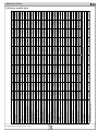
Labornetzgeräteserie
PS 8000 T
PS 8016-20T:
PS 8032-10T:
PS 8065-05T:
PS 8032-30T:
PS 8065-10T:
09 200 120
09 200 121
09 200 122
09 200 123
09 200 124
PS 8160-04T:
PS 8080-40T:
PS 8080-60T:
PS 8360-10T:
PS 8360-15T:
09 200 125
09 200 126
09 200 127
09 200 128
09 200 129
DE
Allgemeines
Impressum
Bedienungsanleitung Labornetzgerät Serie PS 8000T
Elektro-Automatik GmbH & Co. KG
Helmholtzstrasse 31-33
41747 Viersen
Germany
Telefon: +(49) 02162 / 37850
Fax: +(49) 02162 / 16230
Web: www.elektroautomatik.de
Mail: [email protected]
Sicherheitshinweise
•Das Gerät ist nur mit der angegebenen Netzspannung zu betreiben
•Keine mechanischen Teile, insbesondere aus Metall, durch die
Lüftungsschlitze in das Gerät einführen!
•Die Verwendung von Flüssigkeiten aller Art in der Nähe des Gerätes ist zu vermeiden, diese könnten in das Gerät gelangen
•Keine Spannungsquellen an den Ausgang des Gerätes anschließen, die die Nennspannung des Gerätes übersteigen können
•Um eine Schnittstellenkarte in dem dafür vorgesehenen Einschub
© Elektro-Automatik
Nachdruck, Vervielfältigung oder auszugsweise, zweck-entfremdete
Verwendung dieser Bedienungsanleitung sind verboten und können
bei Nichtbeachtung rechtliche Schritte nach sich ziehen.
Stand: Januar 2009
zu bestücken, müssen die einschlägigen ESD- Vorschriften beachtet werden.
•Die Schnittstellenkarte darf nur im ausgeschalteten Zustand
aus
dem Einschub herausgenommen oder bestückt werden. Eine
Öffnung des Gerätes ist nicht erforderlich.
Inhaltsverzeichnis
1. Einleitung
4
2. Technische Daten
2.1 Bedien- und Anzeigeeinheit
2.2 Gerätespezifische Daten
4
4
5
3. Gerätebeschreibung
3.1 Frontansicht
3.2 Rückansicht
3.3 Lieferumfang
6
6
7
7
4. Allgemeines zum Gerät
4.1 Vorwort / Warnhinweis
4.2 Kühlung
4.3 Gerät öffnen
7
7
7
7
5. Installation
5.1 Sichtprüfung
5.2 Netzanschluss
5.3 Anschluss DC-Ausgang
5.4 Anschlussklemme Sense (Fernfühlung) 5.5 Slot für Erweiterungskarte
7
7
7
7
8
8
6. Bedienung
6.1 Die Anzeige
6.2 Tasten am Bedienfeld
6.3 Weitere Bedienelemente
6.4 Sollwerte einstellen
8
8
8
9
9
7. Verhalten bei ...
7.1 Einschalten mit dem Netzschalter
7.2 Ausschalten mit dem Netzschalter
7.3 Ein- oder Ausschalten mit der Taste Standby
7.4 Umschalten auf Fernsteuerung (Remote)
7.4 Überspannung
7.5 Übertemperatur
7.6 Spannungs-/Stromregelung
7.7 Fernfühlungsbetrieb
7.8 Netzüber-/Netzunterspannung
10
10
10
10
10
10
11
11
11
11
8. Geräte-Setup
11
9. Digitale Schnittstellenkarten
12
10. Analoge Schnittstelle
10.1 Allgemeines
10.2 Anwendungen
12
12
12
© 2009, Elektro-Automatik GmbH & Co. KG
Irrtümer und Änderungen vorbehalten
DE
Über das Gerät
1. Einleitung
Die Labornetzgeräte der Serie PS 8000T sind kompakte und
robuste Geräte, die auf kleinem Raum eine Vielzahl von interessanten Möglichkeiten bieten. Über die gängigen Funktionen von
Netzgeräten hinaus können 5 verschiedene Sollwertvorgabesätze
eingestellt, gespeichert und bei Bedarf abgerufen werden. Weiterhin ist eine fest integrierte, analoge Schnittstelle, die die gängigen
Spannungsbereiche 0...5V und 0...10V bedient, vorhanden. Diese
ermöglicht zum Einen die Überwachung des Gerätes und zum
Anderen die komplette Fernsteuerung. Mittels optionalen Schnittstellenkarten (CAN, RS232, USB oder IEEE/GPIB) können von
einem PC aus nahezu alle Funktionen des Gerätes gesteuert und
das Gerät werden.
Die Integration in bestehende Systeme ist mittels der Schnittstellenkarte leicht möglich, die Konfiguration ist einfach und wird am
Gerät erledigt, sofern überhaupt nötig. Die Labornetzgeräte können
so z. B. über die analoge Schnittstelle im Verbund mit anderen Labornetzgeräten betrieben werden bzw. von einer SPS oder einem
anderem Gerät mit analoger Schnittstelle gesteuert werden oder
dieses steuern.
Das Gerät ist mikroprozessorgesteuert und erlaubt eine genaue
und schnelle Messung und Anzeige von Istwerten.
Das Tower-Design ermöglicht platzsparende Konzeptionierung
selbst von aufwendigen und leistungsfähigen Anwendungen, wie
z. B. industrielle Prüfsysteme mit variablen Leistungen für die
unterschiedlichsten Anwendungen oder zu Demonstrations- und
Testzwecken im Entwicklungs- oder Ausbildungsbereich.
Die Hauptfunktionen im Überblick:
»
Stellen von Strom und Spannung, jeweils 0...100%
»
Einstellbarer Überspannungsschutz 0...110% Unenn
»
Wechselbare Schnittstellenkarten (CAN, USB, RS232,
IEEE/GPIB)
»
Analoge Schnittstelle für externe Ansteuerung und Messung
mit 0...5V oder 0...10V (umschaltbar) für 0...100%
»
Leistungsklassen 320W, 640W, 1000W und 1500W
»
Temperaturgesteuerte Lüfterregelung
»
Zustandsanzeigen (OT, OVP, CC, CV) über LEDs
»
Energiesparmodus (Standby)
»
5 speicherbare Sollwertsätze
2. Technische Daten
2.1Bedien- und Anzeigeeinheit
Ausführung
Anzeige:
LED-Sieben-Segment-Anzeige mit vier Stellen plus Komma, LEDs
Bedienelemente:
2 Drehimpulsgeber, 6 Tasten
Anzeigeformate
Die Nennwerte bestimmen den maximal einstellbaren Bereich.
Ist- und Sollwerte werden für Spannung und Strom stets gleichzeitig
dargestellt, der Sollwert für den Überspannungsschutz separat.
Anzeige von Spannungswerten
Auflösung: Genauigkeit:
Formate:
4-stellig
max. ±0,2% von Unenn
0.00V...16.00V
0.00V...32.00V
0.00V...65.00V
0.00V...80.00V
0.0V…160.0V
0.0V...360.0V
Anzeige von Stromwerten
Auflösung: Genauigkeit:
Formate:
4-stellig
max. ±0,2% von Inenn
0.000A…4.000A
0.000A...5.000A
0.00A...10.00A
0.00A...15.00A
0.00A...20.00A
0.00A...40.00A
0.00A...60.00A
© 2006, Elektro-Automatik GmbH & Co. KG
Irrtümer und Änderungen vorbehalten
© 2009, Elektro-Automatik GmbH & Co. KG
Irrtümer und Änderungen vorbehalten
© 2009, Elektro-Automatik GmbH & Co. KG
Irrtümer und Änderungen vorbehalten
* Bezogen auf den Nennwert
Netzeingang
Eingangsspannung
Frequenz
Eingangsstrom max.
Sicherung
Leistungsfaktor
Einschaltstrom
Leistungsaufnahme Output off
Leistungsaufnahme Standby
Ausgang - Spannung
Nennspannung Unenn
Einstellbereich
Stabilität Netzausregelung ±10% ?UE
Stabilität bei 10…90% Last
Restwelligkeit
Genauigkeit*
Auflösung der Anzeige
Senseausregelung
Überspannungsschutz (einstellbar)
Ausgang - Strom
Nennstrom Inenn
Einstellbereich
Stabilität Netzausregelung ±10% ?UE
Stabilität bei 0…100% ?UA
Restwelligkeit
Genauigkeit*
Auflösung der Anzeige
Ausregelzeit 10….90% Last
Ausgang - Leistung
Nennleistung Pnenn
Nennleistung < 150V UE
Verschiedenes
Betriebstemperatur
Lagertemperatur
Luftfeuchtigkeit rel.
Abmessungen (BxHxT)
Gewicht
Sicherheit
EMV-Normen
Überspannungskategorie
Schutzklasse
Artikelnummer
90…264V
45…65HZ
4A
T 4A
> 0.99
< 25A
12W
7W
2V
0V…Unenn
< 0.02%
< 0.05%
< 40mVpp
= 0.2%
10mV
max. 2.0V
0…5.2V
0…10A
0A…Inenn
< 0.05%
< 0.15%
< 50mApp
= 0.2%
10mA
< 2ms
20W
20W
90…264V
45…65HZ
4A
T 4A
> 0.99
< 25A
12W
7W
16V
0V…Unenn
< 0.02%
< 0.05%
< 40mVpp
= 0.2%
10mV
max. 2.0V
0…17.6V
0…20A
0A…Inenn
< 0.05%
< 0.15%
< 50mApp
= 0.2%
10mA
< 2ms
20W
20W
25W
25W
0…5A
0A…Inenn
< 0.05%
< 0.15%
< 50mApp
= 0.2%
1mA
< 2ms
65V
0V…Unenn
< 0.02%
< 0.05%
< 40mVpp
= 0.2%
10mV
max. 2.0V
0…71.5V
90…264V
45…65HZ
4A
T 4A
> 0.99
< 25A
12W
7W
PS 8065-05 T
640W
640W
0…20A
0A…Inenn
< 0.05%
< 0.15%
< 50mApp
= 0.2%
10mA
< 2ms
2V
0V…Unenn
< 0.02%
< 0.05%
< 40mVpp
= 0.2%
10mV
max. 2.0V
0….5.2V
90…264V
45…65HZ
8A
T 8A
> 0.99
< 25A
12W
7W
PS 8032-20 T
640W
640W
0…10A
0A…Inenn
< 0.05%
< 0.15%
< 50mApp
= 0.2%
10mA
< 2ms
65V
0V…Unenn
< 0.02%
< 0.05%
< 40mVpp
= 0.2%
10mV
max. 2.0V
0…5.2V
90…264V
45…65HZ
8A
T 8A
> 0.99
< 25A
12W
7W
PS 8065-10 T
640W
640W
0…4A
0A…Inenn
< 0.05%
< 0.15%
< 50mVpp
= 0.2%
1mA
< 2ms
160V
0V…Unenn
< 0.02%
< 0.05%
< 40mVpp
= 0.2%
100mV
max. 2.0V
0…176V
90…264V
45…65HZ
8A
T 8A
> 0.99
< 25A
12W
7W
PS 8160-04 T
1000W
1000W
0…40A
0A…Inenn
< 0.05%
< 0.15%
< 100mApp
= 0.2%
10mA
< 2ms
1500W
1000W
0…60A
0A…Inenn
< 0.05%
< 0.15%
< 100mApp
= 0.2%
10mA
< 2ms
80V
0V…Unenn
< 0.02%
< 0.05%
< 70mVpp
= 0.2%
10mV
max. 2.0V
0…88V
T 16A
> 0.99
< 25A
1W
11W
T 16A
> 0.99
< 25A
1W
11W
80V
0V…Unenn
< 0.02%
< 0.05%
< 70mVpp
= 0.2%
10mV
max. 2.0V
0…88V
90…264V
45…65HZ
PS 8080-60 T
90…264V
45…65HZ
PS 8080-40 T
1000W
1000W
0…10A
0A…Inenn
< 0.05%
< 0.15%
< 15mApp
= 0.2%
10mA
< 2ms
60V
0V…Unenn
< 0.02%
< 0.05%
< 100mVpp
= 0.2%
100mV
max. 2.0V
0…96V
T 16A
> 0.99
< 25A
1W
11W
90…264V
45…65HZ
PS 8360-10 T
1500W
1000W
0…15A
0A…Inenn
< 0.05%
< 0.15%
< 15mApp
= 0.2%
10mA
< 2ms
60V
0V…Unenn
< 0.02%
< 0.05%
< 100mVpp
= 0.2%
100mV
max. 2.0V
0…96V
T 16A
> 0.99
< 25A
1W
11W
90…264V
45…65HZ
PS 8360-15 T
0….40°C
0….40°C
0….40°C
0….40°C
0….40°C
0….40°C
0….40°C
0….40°C
0….40°C
0….40°C
-20….70°C
-20….70°C
-20….70°C
-20….70°C
-20….70°C
-20….70°C
-20….70°C
-20….70°C
-20….70°C
-20….70°C
< 80%
< 80%
< 80%
< 80%
< 80%
< 80%
< 80%
< 80%
< 80%
< 80%
90x240x280mm 90x240x280mm 90x240x280mm 90x240x280mm 90x240x280mm 90x240x280mm 90x240x95mm 90x240x95mm 90x240x95mm 90x240x95mm
5kg
5kg
5kg
5kg
5kg
5kg
9kg
9,kg
9kg
9,kg
EN 60950
EN 6126, EN 55022 Klasse B
Klasse II
KlasseI
09200120
09200121
09200122
0920012
09200124
09200125
09200126
09200127
09200128
09200129
PS 8032-10 T
PS 8016-20 T
Über das Gerät
DE
2.2Gerätespezifische Daten
DE
Über das Gerät
3. Gerätebeschreibung
3.1
Frontansicht
Beschreibung der Bedien- und Anschlußelemente:
1)
Leistungsausgang, gepolt, Sicherheitsbuchsen
Die Buchsen können zum Einstecken von 4mm Büschelsteckern oder zum Festklemmen von Gabelkabelschuhen verwendet werden.
2)
Fernfühlungseingang (Sense), gepolt
Hier werden die Fernfühlungsleitungen polrichtig angeschlossen. Mehr zur Fernfühlung siehe Abschnitt „Fernfühlungsbetrieb“.
3)
Analoge Schnittstelle, 15polig, Sub-D, weiblich
Dient zum Fernsteuern bzw. zur Überwachung des Gerätes mit
analogen und digitalen Signalen. Mehr dazu siehe Abschnitt
„Analoge Schnittstelle“.
4)
Standby-Taster
Dient zum Ein-/Ausschalten des Energiesparbetriebes
(Standby).
5)
Drehgeber rechts, ohne Anschlag
Dient zur Einstellung des Stromsollwertes.
Ungefähr 5 komplette Drehungen entsprechen 0...100%.
Im Setup zur Einstellung von Parametern.
Mehr dazu siehe Abschnitte „Sollwerte einstellen“ und „Geräte-Setup“.
6)
Drehgeber links, ohne Anschlag
Dient zur Einstellung des Spannungssollwertes. Im Voreinstellmodus (Preset) zusätzlich zur Einstellung der OVPGrenze.
Ungefähr 5 komplette Drehungen entsprechen 0...100%.
Im Setup zur Einstellung von Parametern.
Mehr dazu siehe Abschnitte „Sollwerte einstellen“ und „Geräte-Setup“.
7)
Anzeige- und Bedienfeld
© 2006, Elektro-Automatik GmbH & Co. KG
Irrtümer und Änderungen vorbehalten
Bild 1
© 2009, Elektro-Automatik GmbH & Co. KG
Irrtümer und Änderungen vorbehalten
DE
Über das Gerät
3.2
Rückansicht
3.3
Lieferumfang
1 x Netzgerät
1 x Gedruckte Bedienungsanleitung
1 x Netzkabel
4. Allgemeines zum Gerät
4.1
Vorwort / Warnhinweis
Diese Bedienungsanleitung und das zugehörige Gerät sind für
Anwender gedacht, die sich mit der Funktion eines Netzgerätes und
dessen Anwendung auskennen. Die Bedienung des Gerätes sollte
nicht Personen überlassen werden, denen die Grundbegriffe der
Elektrotechnik unbekannt sind, da sie durch diese Anleitung nicht
erläutert werden. Unsachgemäße Bedienung und Nichteinhaltung
der Sicherheitsvorschriften können zur Beschädigung des Gerätes,
des Bedieners sowie zu Garantieverlust führen!
4.2
Kühlung
Die Lufteinlässe in den Seiten und der Luftaustritt in der Rückseite
sind immer frei und sauber zu halten, sowie ein Mindestabstand
von 10cm hinter der Rückwand freizuhalten, um ausreichende
Luftzufuhr zu gewährleisten.
4.3
Gerät öffnen
Beim Öffnen des Gerätes oder beim Entfernen von Teilen mit Hilfe
von Werkzeugen, können Teile berührt werden, die gefährliche
Spannung führen. Das Gerät muss deshalb vor dem Öffnen von
allen Spannungsquellen getrennt sein.
Das Arbeiten am geöffneten Gerät darf nur durch eine Elektrofachkraft durchgeführt werden, die über die damit verbundenen
Gefahren informiert ist.
5. Installation
5.1
Sichtprüfung
Das Gerät ist nach der Lieferung auf Beschädigungen zu überprüfen. Sollten Beschädigungen oder technische Fehler erkennbar
sein, darf das Gerät nicht angeschlossen werden. Außerdem
sollte unverzüglich der Händler verständigt werden, der das Gerät
geliefert hat.
5.2
Netzanschluss
Das Gerät wird über das beiliegende Netzanschlußkabel geerdet.
Deshalb darf das Gerät nur an einer Schutzkontaktsteckdose betrieben werden. Diese Maßnahme darf nicht durch Verwendung einer
Anschlussleitung ohne Schutzleiter unwirksam gemacht werden.
Die Absicherung des Gerätes erfolgt über eine 5 x 20mm Schmelzsicherung, die sich in der Netzbuchse in einer Schublade befindet.
5.3
Anschluss DC-Ausgang
Der Lastausgang befindet sich auf der Vorderseite des Gerätes.
Der Ausgang ist nicht über eine Sicherung abgesichert. Um Beschädigungen des Verbrauchers zu vermeiden, sind die für den
Verbraucher zulässigen Nennwerte stets zu beachten.
Bild 2
© 2009, Elektro-Automatik GmbH & Co. KG
Irrtümer und Änderungen vorbehalten
Der Querschnitt der Ausgangsleitungen richtet sich u. A. nach der
Stromaufnahme, der Leitungslänge und der Umgebungstemperatur.
DE
Über das Gerät
Bei Leitungen bis 1,5m empfehlen wir:
bis 5A:
0,5mm², bis 10A:0,75mm²
bis 15A:
1,5mm²
bis 20A:2,5mm²
bei 40A:
6mm²,
bis 60A:16mm²
pro Anschlußleitung (Litze, frei verlegt) mindestens zu verwenden.
Die Eingänge “+” und “-“ sind erdfrei, so daß bei Bedarf einer von
beiden geerdet werden kann.
Achtung! Bei Erdung einer der Eingangspole muß beachtet
werden, ob am Verbraucher (z. B. elektronische Last) nicht
auch ein Ausgangspol geerdet ist. Dies kann u. U. zu einem
Kurzschluß führen!
Achtung! Bei Reihenschaltung mehrerer Netzgeräte ist die
Potentialverschiebung der Ausgangspole zu berücksichtigen!
Erdung ist dann nur am Ausgang mit dem kleinsten Potential
zu empfehlen.
5.4
Anschlussklemme Sense (Fernfühlung)
Soll der Spannungsabfall auf den Zuleitungen (max. 1V pro Leitung)
vom Netzgerät zum Verbraucher hin kompensiert werden, kann das
Netzgerät die Spannung am Verbraucher an der Klemme Sense
messen und daraufhin regeln.
Der Anschluss erfolgt polrichtig an der Vorderseite des Gerätes an
der Klemme Sense.
!
se nur am (–) des Verbrauchers angeschlossen werden.
Ansonsten können beide Geräte beschädigt werden.
Slot für Erweiterungskarte
Das Gerät kann optional mit einer Steckkarte ausgestattet werden.
Der Anschluß hierfür befindet sich auf der Rückseite des Gerätes.
Weitere Informationen über die Erweiterungskarten, hier auch
Schnittstellenkarten genannt, sind im Abschnitt „Digitale Schnittstellenkarten“ zu finden.
6. Bedienung
6.1
6.2
Tasten am Bedienfeld
Taste Preset V/C/OVP
(+) Sense darf nur am (+) des Verbrauchers und (–) Sen-
Weitere Informationen über den Fernfühlungbetrieb siehe Abschnitt
„Fernfühlungsbetrieb“.
5.5
Bild 3
Die Anzeige
Bild 3 zeigt eine Übersicht über die zwei vierstelligen 7-SegmentAnzeigen (7S) und das Bedienfeld. Die Anzeigen stellen im Normalbetrieb die Istwerte für Spannung (oben) und Strom (unten) dar,
im Preset-Modus den Sollwert für Spannung (oben), Strom (unten)
und die OVP-Grenze (oben), sowie Parameter und Einstellungen
im Geräte-Setup.
Dient zum Umschalten der 7-Segment-Anzeige auf die Sollwerte
(Preset-Modus). Ein Druck auf Taste schaltet auf die Sollwertanzeige für U und I um, ein zweiter Druck auf den Sollwert für die OVPGrenze. Hierbei wird zur Orientierung in der unteren Anzeige „OVP“
angezeigt. Die LED über der Taste zeigt den Preset-Modus an. Mit
den beiden Drehgebern können die Sollwerte Unenn bzw. Inenn
von 0...100% oder OVP von 0...110% Unenn eingestellt werden.
Die eingestellten Werte werden immer sofort übernommen.
Ein dritter Druck auf die Taste beendet den Preset-Modus. Er wird
auch automatisch beendet, wenn 5s lang kein Sollwert verändert
wird.
Im Remote-Betrieb (analoge oder digitale Schnittstelle) können
hier die über die momentan benutzte Schnittstelle vorgegebenen
Sollwerte kontrolliert werden. Bei Steuerung des Gerätes über
die analoge Schnittstelle kann die OVP-Grenze nicht von außen
verändert werden. Die Preset-Anzeige zeigt dann den zuletzt
eingestellten Wert an.
Die Taste kann durch den Zustand LOCK blockiert sein. Siehe
unten.
Taste Memory M1...M5
Die Status-LEDs (rechts) zeigen folgendes an:
CV - Spannungsregelung aktiv (nur bei Ausgang „ein“)
OT - Übertemperaturfehler
OVP - Überspannungsfehler
CC - Stromregelung aktiv (nur bei Ausgang „ein“)
Rem - Fernsteuerung aktiv (digital oder analog)
Local - LOCAL-Modus aktiv
© 2006, Elektro-Automatik GmbH & Co. KG
Irrtümer
und Änderungen
Diese Taste hat
zwei Funktionen
undvorbehalten
wählt einen von 5 Sollwertsätzen mit jeweils U, I, OVP zum Übernehmen aus oder bewirkt die
Speicherung aller 5 Sollwertsätze. Die Taste funktioniert nur wenn
der Ausgang ausgeschaltet ist. Der Memory-Modus wird mit der
LED über der Taste angezeigt. Folgende Bedienmöglichkeiten:
a) Auswählen und Einstellen
Ausgang aus, Taste einmal kurz betätigt, die Anzeige wechselt auf
den ersten Sollwertsatz M1.
© 2009, Elektro-Automatik GmbH & Co. KG
Irrtümer und Änderungen vorbehalten
DE
Bedienung des Gerätes
Angezeigt wird dies durch ein kurzes Einblenden der Memorysetnummer:
Erst nach Freigabe, also Deaktivierung von LOCAL, ist wieder
Fernsteuerung möglich
Folgende Bedienmöglichkeiten:
Anschließend werden die Sollwerte für U (oben) und für I (unten)
des gewählten Sollwertsatzes angezeigt. Umschalten auf den
Sollwert OVP des gewählten Sollwertsatzes wie im Preset-Modus
mit der Taste V/C/OVP.
Bei weiterer Betätigung der Taste Memory M1...M5 wird bis zum
5. Satz durchgeschaltet und danach beendet.
b) Nur übernehmen
Ausgang aus, Sollwertsatz gewählt (1-5), Taste Output On betätigen --> die Sollwerte des gewählten Sollwertsatzes werden
übernommen und der Ausgang eingeschaltet.
a) Kurzer Druck --> LOCK ein/aus = Sperre aller Bedienfeldtasten
und der Drehgeber, außer der Lock-Taste selbst. Der LOCK-Modus
wird durch die LED über der Taste angezeigt. Durch die Sperre des
Bedienfeldes kann ein versehentliches Betätigen einer Taste oder
das Verstellen von Sollwerten verhindert werden.
b) Druck >3s (sofern LOCK nicht aktiv) --> LOCAL ein/aus, bei „ein“
wird der Bedienort auf manuell festgelegt. Das bedeutet, daß das
Gerät nicht über die digitale oder analoge Schnittstelle gesteuert
werden kann. Es wird also der Wechsel in Remote verhindert bzw.,
sofern Remote schon aktiviert war, beendet. Der aktivierte LOCALModus wird durch die LED Local angezeigt.
Taste Output on
Achtung! Die Sollwerte hiermit nicht gespeichert!
c) Nur speichern
Ausgang aus, einen oder mehrere Sollwertsätze anwählen, Sollwerte einstellen, dann Druck >3s auf die Taste Memory M1...M5 -->
alle Sollwertsätze werden gespeichert, aber keiner übernommen.
Der Ausgang bleibt aus, nach dem Speichern wird der MemoryModus beendet.
Die Taste kann durch den Zustand LOCK blockiert sein.
Dient zum manuellen Ein- oder Ausschalten des Leistungsausganges, sofern sich das Gerät nicht im Fernsteuerbetrieb befindet. Der
Zustand des Ausganges wird mit der LED über der Taste angezeigt.
Bei eingeschaltetem Ausgang wird die aktuelle Regelungsart, CC
oder CV, über die jeweilige LED angezeigt. Bei ausgeschaltetem
Ausgang sind die LEDs aus.
Die Taste kann durch den Zustand LOCK blockiert sein.
Taste Fine/Setup
Diese Taste hat zwei Funktionen und wechselt zwischen Grobeinstellmodus und Feineinstellmodus hin und her oder wechselt in
das Geräte-Setup (nur bei Ausgang aus). Folgende Bedienmöglichkeiten:
a) Kurzer Druck --> Feineinstellmodus ein/aus. Den aktivierten
Feineinstellmodus zeigt die LED über der Taste Fine/Setup an.
Alle Sollwerte können bei „Fine“ mit den Drehgebern nun in den
kleinstmöglichen Schritten eingestellt werden. Deaktivierung des
Feinstellmodus wechselt in den Grobeinstellmodus. Siehe auch
Abschnitt „Sollwerte einstellen“.
b) Ausgang aus, Druck >3s --> Geräte-Setup wird angezeigt.
Näheres dazu im Abschnitt „Geräte-Setup“. Nachdem die Geräteeinstellungen getätigt wurden, Druck >3s --> Geräte-Setup wird
beendet, die Einstellungen gespeichert und die LED über der Taste
blinkt zweimal.
Die Taste kann durch den Zustand LOCK blockiert sein.
Taste Lock/Local
Diese Taste hat zwei Funktionen und aktiviert/deaktiviert den
Bedienfeldsperre (LOCK) oder aktiviert/deaktiviert den LOCALModus.
Achtung! Aktivieren des LOCAL-Modus hat die sofortige Beendigung der externen Steuerung (analog oder digital) zur Folge und
sperrt das Gerät gegen erneute Fernsteuerung.
© 2009, Elektro-Automatik GmbH & Co. KG
Irrtümer und Änderungen vorbehalten
Das Einschalten des Ausganges kann durch den Pin 13 (REM-SB)
der analogen Schnittstelle blockiert sein! Siehe Abschnitt „Analoge
Schnittstelle“.
Die Taste quittiert den Überspannungsfehler OVP. Das heißt, wenn
die Ursache des OVP-Fehler bereits beseitigt wurde oder weg ist,
bleibt die LED „OVP“, bis der Ausgang erneut eingeschaltet wird.
6.3
Weitere Bedienelemente
Taste Standby (4)
Aktiviert bzw. deaktiviert zu jeder Zeit den Standby-Betrieb (Energiesparmodus). Bei Betätigung werden momentan gewählte Modi
(Memory, Preset, Setup usw,) beendet und sämtliche Anzeigeelemente ausgeschaltet. Ist dabei das Geräte-Setup aktiv, werden
Einstellungen nicht gespeichert!
6.4
Sollwerte einstellen
1. Manueller Betrieb
Mit den beiden Drehgebern können im laufenden Betrieb die Sollwerte für Spannung und Strom kontinuierlich von 0% bis 100%
Nennwert bei Strom und Spannung, sowie 0%...110% Nennspannung für den Überspannungsschutz (OVP) eingestellt werden.
Für die Einstellung des OVP-Sollwertes muß die Taste Preset
V/C/OVP zweimal betätigt werden. Der OVP-Sollwert kann auch
kleiner als der Spannungssollwert sein und löst in einem solchen
Fall bei eingeschaltetem Ausgang sofort einen OVP-Fehler aus,
sobald der Istwert den OVP-Sollwert übersteigt!
Weiter auf der nächsten Seite...
DE
Bedienung des Gerätes
Manuelle Sollwerteinstellung kann grob oder fein erfolgen, wobei
grob die Standardeinstellungsart ist und fein erst über die Taste
„Fine“ aktiviert werden muß. Bei fein gilt stets eine Schrittweite
von 1, dies entspricht der letzten (rechten) Stelle des angezeigten
Sollwertes.
Bei GPIB werden Sollwerte immer als reale Werte vorgegeben.
Bei grob gelten folgende Schrittweiten in Abhängigkeit vom Nennwert (siehe Gerätedaten):
7. Verhalten bei ...
Spannung
Nennwert
Schrittweite
16V
0,1V
32V
0,2V
65V
0,5V
80V
0,5V
160V
1V
360V
2V
Strom
Nennwert
Schrittweite
4A
50mA
5A
50mA
10A
0,1A
15A
0,1A
20A
0,2A
40A
0,5A
60A
0,5A
Wichtig! Die Auflösung des einstellbaren Sollwertes ist bei manchen Geräten höher als die der Ausgangsspannung. Daher kann
es vorkommen, daß bei feineingestellten Schritten erst alle 2-3
Schritte eine Änderung der Ausgangsspannung erfolgt.
2. Fernsteuerbetrieb über analoge Schnittstelle
Über die analoge Schnittstelle (AS) können Strom und Spannung
gestellt werden. Dies geschieht immer gleichzeitig. Das heißt, man
kann nicht Spannung über die AS vorgeben und den Strom am
Gerät mit dem Drehgeber oder umgekehrt. Da der OVP-Sollwert
über analog nicht gestellt werden kann, ist dieser vorher am Gerät
einzustellen. Ein Umschalten auf Preset-Anzeige zeigt auf den Anzeigen die analog vorgegebenen Sollwerte an. Zur Erzeugung der
analogen Sollwerte kann eine externe Spannung eingespeist oder
die am Pin 3 ausgegebene Referenzspannung genutzt werden.
Möchte man z. B. nur Spannung regeln, kann man hier den Stromsollwert zur Referenzspannung hin brücken.
Die AS kann mit den gängigen Spannungsbereichen 0...5V oder
0...10V für jeweils 0...100% Nennwert betrieben werden. Der zu
verwendende Spannungsbereich ist im Geräte-Setup zu wählen.
Es gilt dann folgendes:
0-5V: Referenzspannung = 5V, 0...5V Sollwert entsprechen
0...100% Nennwert, 0...100% Istwert ensprechen 0...5V an den
Istwertausgängen.
0-10V: Referenzspannung = 10V, 0...10V Sollwert entsprechen
0...100% Nennwert, 0...100% Istwert ensprechen 0...10V and den
Istwertausgängen.
Vorgabe von zu hohen Sollwerten (z. B. >5V im gewählten 5VBereich) wird abgefangen, in dem der jeweilige Sollwert auf 100%
bleibt.
Niemals Spannungen >12V an den Sollwerteingängen anlegen!
3. Fernsteuerbetrieb über digitale Schnittstelle
Über die digitale Schnittstelle können Strom-, Spannungs- und
OVP-Sollwert gesetzt werden. Bei Wechsel auf Fernsteuerung
werden die zuletzt am Gerät eingestellten Werte beibehalten, bis
sie geändert werden. Somit wäre eine reine Spannungssteuerung
durch Vorgabe von Spannungssollwerten möglich, wenn der Stromsollwert unverändert bliebe.
Sollwerte, die über die digitale Schnittstellen (außer GPIB) vorgegeben werden, sind immer Prozentwerte und entsprechen bei 100%
(hex: 0x6400) bzw. bei 110% (hex: 0x6E00) beim OVP-Sollwert
den Nennwerten des Gerätes.
10
Über die digitale Schnittstelle können viele weitere Funktionen
des Gerätes gesteuert bzw. Werte gesetzt oder abgefragt werden.
Näheres dazu siehe Abschnitt „Digitale Schnittstellenkarten“.
7.1
Einschalten mit dem Netzschalter
Der Netzschalter befindet sich auf der Rückseite. Nach dem
Einschalten ist das Gerät sofort betriebsbereit. Im Setup (siehe
Abschnitt „Geräte-Setup“) befindet sich eine Option, „P on“ (Auto
Power On) die bestimmt, wie der Zustand des Gerätes nach dem
Einschalten ist. Werksseitig ist diese aktiviert (=on). Das bedeutet,
daß die Sollwerte und der Zustand des Ausganges (ein oder aus)
wiederhergestellt werden, so wie sie beim letzten Ausschalten waren. Ist die Option „off“, werden die Sollwerte für U und I nach dem
Einschalten auf 0 gesetzt und der Ausgang wird eingeschaltet.
7.2
Ausschalten mit dem Netzschalter
Das Ausschalten mit dem Netzschalter wird als Stromausfall
behandelt. Das Gerät speichert den Zustand des Ausganges
und die zuletzt eingestellten Sollwerte. Nach kurzer Zeit werden
Leistungsausgang und Lüfter abgeschaltet, das Gerät ist nach ein
paar weiteren Sekunden dann komplett aus.
7.3
Ein- oder Ausschalten mit der Taste Standby
Funktioniert in Bezug auf die Wiederherstellung des letzten Zustandes wie beim Einschalten mit dem Netzschalter. Der letzte Zustand
wird entweder hergestellt oder ein Standardzustand wird gesetzt.
Dies ist abhängig von der Einstellung „P on“ im Geräte-Setup.
7.4
Umschalten auf Fernsteuerung (Remote)
Folgende Verhaltensweisen:
a) Analoge Schnittstelle: Umschalten mit Pin „Remote“ schaltet
auf Steuerung des Gerätes mit den Sollwertpins VSEL und CSEL,
sowie REM-SB um. Der Ausgangszustand und die Sollwerte, die
über die Pins 1, 2 und 13 (siehe auch Abschnitt „Analogschnittstelle“) vorgegeben sind werden sofort gesetzt. Nach Rückkehr von
der Fernsteuerung in die manuelle Steuerung wird der Ausgang
ausgeschaltet und die zuletzt von außen vorgegebenen Sollwerte
(U und I) werden beibehalten.
b) Digitale Schnittstelle: Umschalten auf Remote-Betrieb mittels
des entsprechenden Befehls übernimmt die zuletzt eingestellten
Sollwerte und den Zustand des Ausganges. Nach Rückkehr von
der Fernsteuerung in die manuelle Steuerung wird der Ausgang
ausgeschaltet und die zuletzt von außen vorgegebenen Sollwert
(U und I) werden beibehalten.
7.4
Überspannung
Ein Überspannungsfehler (OVP) kann auftreten durch einen internen Fehler (Ausgangsspannung läuft hoch) oder durch eine
zu hohe Spannung von außen. Der Überspannungsschutz wird in
beiden Fällen das Leistungsteil und somit die Ausgangsspannung
abschalten und den Fehler durch die LED „OVP“ angezeigt.
© 2006, Elektro-Automatik GmbH & Co. KG
Überhöhte Spannung
Nennspannung)
von außen
Irrtümer und (>120%
Änderungen
vorbehalten
ist unbedingt zu vermeiden, da Bauteile im Inneren zerstört
werden können!
Ist keine Überspannung mehr vorhanden, kann der Ausgang wieder
eingeschaltet werden. Die LED „OVP“ erlischt dann. Bei manuellem Betrieb geschieht dies mit der Taste Output On, bei analoger
Fernsteuerung mit dem Pin „Rem-SB“. Ist der Fehler weiterhin
vorhanden, kann der Ausgang nicht eingeschaltet werden.
© 2009, Elektro-Automatik GmbH & Co. KG
Irrtümer und Änderungen vorbehalten
DE
Bedienung des Gerätes
OVP-Fehler werden als Alarm im internen Alarm-Puffer eingetragen. Dieser Puffer kann über die digitale Schnittstelle ausgelesen
werden.
7.5
Übertemperatur
Überhöhte Umgebungstemperatur ist unbedingt zu vermeiden!
Sobald ein Übertemperaturfehler (OT) durch interne Überhitzung
auftritt, wird der Ausgang abgeschaltet und die LED „OT“ leuchtet.
Gleichzeitig blinkt die LED „Output“ um anzuzeigen, daß sich der
Ausgang nach dem Abkühlen automatisch wieder einschaltet. Soll
dies nicht geschehen, kann der Ausgang während der Übertemperaturphase manuell mit der Taste Output on/off abgeschaltet
werden, die LED „Output“ blinkt dann nicht mehr und der Ausgang
schaltet sich nicht automatisch ein.
OT-Fehler werden als Alarm im internen Alarm-Puffer eingetragen. Dieser Puffer kann über die digitale Schnittstelle ausgelesen
werden.
7.6
Spannungs-/Stromregelung
Die am Ausgang eingestellte Spannung und der Widerstand des
Verbrauchers bestimmen den Ausgangsstrom. Ist dieser kleiner
als die am Gerät eingestellte Strombegrenzung, arbeitet das Gerät
im Spannungsregelbetrieb (CV) und hält die Ausgangsspannung
konstant. Angezeigt wird die Betriebsart durch die LED „CV“.
Wird der Ausgangsstrom durch den Stromsollwert oder den
Nennstrom des Gerätes begrenzt, so wechselt das Gerät in den
Stromregelbetrieb (CC), der den Ausgangsstrom konstant hält.
Diese Betriebsart wird durch die LED „CC“ angezeigt.
7.7
Fernfühlungsbetrieb
Fernfühlungsbetrieb, auch „Remote sense“ genannt, soll Spannung, die über die Lastleitungen zum Verbraucher hin abfällt,
kompensieren. Dies kann jedoch nur bis zu einem gewissen Grad
geschehen. Daher ist der Leitungsquerschnitt der Lastleitungen
dem zu entnehmenden Strom stets anpassen, um den Spannungsabfall so gering wie möglich zu halten. Auf der Vorderseite ist ein
Fernfühlungseingang vorhanden der am Verbraucher polrichtig
angeschlossen wird. Das Gerät erkennt das automatisch und regelt
die Spannung nun am Verbraucher, statt wie vorher am Ausgang.
Die Spannung am Ausgang erhöht sich dadurch um den Betrag
des Spannungsabfalls zwischen Gerät und Verbraucher.
Maximale Ausregelung: 1V pro Leitung.
7.8
Netzüber-/Netzunterspannung
Die Geräte verfügen über eine aktive Gleichrichtung mit PFC
und einen Weitbereichseingang. Das bedeutet, sie können mit
90V...264V betrieben werden. Netzspannungen unter 90V werden
als Netzunterspannung bzw. Ausschalten des Gerätes betrachtet
und führen zur Speicherung der zuletzt eingestellten Sollwerte,
sowie zur Abschaltung des Leitungsteils und des Ausganges.
Dauerhafte Netzunter- oder überspannung muß unbedingt
vermieden werden!
Wichtig! Bei Geräten mit 1500W Nennleistung findet bei ca. 150V
Eingangsspannung oder weniger eine Leistungsreduktion (Derating) auf 1000W statt.
8. Geräte-Setup
Das Geräte-Setup dient zur Konfiguration einiger Parameter, die
nicht ständig benötigt werden. Zwei Grundparameter sind immer
verfügbar. Weitere Parameter werden nur angezeigt, wenn sich
eine Schnittstellenkarte im Slot befindet.
Das Geräte-Setup kann nur bei Ausgang „aus“ durch Drücken
der Taste Fine/Setup >2s erreicht werden. Die schnittstellenspezifischen Parameter, wie z. B. Baudrate, bleiben auch bei einem
Wechsel der Karte erhalten. Die erneute Benutzung z. B. einer
CAN-Karte nach der Benutzung einer RS232-Karte erfordert somit
nicht unbedingt, alle Parameter neu einstellen zu müssen.
Folgende Grundparameter sind einstellbar:
Name: P on Standardwert: on
Wertebereich: on, oFF
Bedeutung: aktiviert mit „on“ die Wiederherstellung des Ausgangszustandes beim Einschalten bzw. Netzwiederkehr auf den letzten
Zustand beim Ausschalten bzw. Netzausfall. Damit kann erreicht
werden, daß das Gerät nach einem Netzausfall mit den alten Sollwerten normal weiterarbeitet.
Name: AI
Standardwert: 0-10
Wertebereich: 0-5, 0-10
Bedeutung: wählt den Spannungsbereich für den Fernsteuerbetrieb
über analoge Schnittstelle aus.
Für alle Schnittstellenkarten folgender Parameter:
Name: nodE
Standardwert: 1
Wertebereich: 1...30
Bedeutung: Wählt die Geräteadresse (device node, aus der CANTerminologie übernommen) für das Gerät. Bei Verwendung mehrerer Geräte an einem Bus (CAN oder GPIB) darf jede Adresse nur
einmal vergeben werden.
Achtung! Für die GPIB-Karte nur Adresse zwischen 1 und 15
wählen, auch wenn bis zur 30 ausgewählt werden kann! Der
GPIB unterstützt nur 15 Adressen.
Folgende Parameter für CAN-Schnittstelle IF-C1:
Name: bAUd
Standardwert: 100
Wertebereich: 10, 25, 50, 100, 125, 250, 500, 1000
Bedeutung: Einstellung der Übertragungsgeschwindigkeit in Kilobaud.
Name: r1d Standardwert: 0
Wertebereich: 0...31
Bedeutung: Einstellung des verschiebbaren Adreßsegments (RID).
Siehe CAN-Terminologie für weitere Informationen.
© 2009, Elektro-Automatik GmbH & Co. KG
Irrtümer und Änderungen vorbehalten
11
DE
Bedienung des Gerätes
Name: btEr Standardwert: on
Wertebereich: on, off
Bedeutung: Aktivierung/Deaktivierung des Busabschlußwiderstandes (bus termination) der CAN-Karte. Der Abschluß ist erforderlich,
wenn die sich das Gerät am Ende des Busses befindet.
Folgender Parameter für RS232-Schnittstelle IF-R1:
Name: bAUd Standardwert: 576
Wertebereich: 96, 192, 384, 576
Bedeutung: Einstellung der Übertragungsgeschwindigkeit in Hektobaud. Das heißt, 96 entspricht 9600 Baud und 576 entspricht
57600 Baud. Weitere Parameter für die serielle Schnittstelle sind
nicht einstellbar, aber wie folgt festgelegt:
Parität = ungerade
Stopbits = 1
Datenbits = 8
und müssen auf der PC-Seite für den jeweiligen Port genauso vorgegeben werden.
9. Digitale Schnittstellenkarten
Das Gerät unterstützt folgende Schnittstellenkarten:
Die Wahl des Spannungsbereiches findet im Geräte-Setup statt,
siehe Abschnitt „Geräte-Setup“. Die am Pin 3 herausgegebene
Referenzspannung wird dabei angepaßt und ist dann, je nach
Wahl, 5V oder 10V.
Hinweise zur Benutzung:
•Steuern des Gerätes mit externen Sollwerten erfordert die
Umschaltung auf Fernsteuerbetrieb mit Pin „REMOTE“ (5).
•Bevor die Hardware, die die analoge Schnittstelle bedienen soll,
verbunden wird, sind alle erforderlichen Leitungen zu legen und
die Hardware zu prüfen, daß diese keine Spannungen >12V
erzeugen kann.
•Der Eingang Rem-SB (Remote Standby, Pin 13) überlagert die
Taste Output On. Das heißt, das Gerät kann dann nicht mit
der Taste eingeschaltet werden, wenn der Pin das Signal „aus“
vorgibt.
•Der Ausgang VREF kann genutzt werden, um Sollwerte für die
Sollwerteingänge VSEL und CSEL zu bilden. Zum Beispiel, wenn
nur Stromregelung gewünscht ist, sollte VSEL auf VREF gebrückt
werden und CSEL wird entweder von extern mit 0...10V bzw.
0...5V gespeist oder über ein Potentiometer zwischen VREF und
Masse.
•Bei Vorgabe von Sollwerten bis 10V bei gewähltem 5V-Bereich
werden diese auf 5V begrenzt (clipping). Das heißt, zwischen 5V
und 10V reagiert das Gerät nicht auf Sollwertänderungen und hält
den entsprechenden Ausgangswert auf 100%.
IF-U1 (USB)
IF-R1 (RS232)
IF-C1 (CAN)
IF-G1 (GPIB/IEEE)
10.2 Anwendungen
Übersicht Sub-D-Buchse
Die Schnittstellenkarten benötigen nur wenige oder keine Einstellungen für den Betrieb. Die kartenspezifischen Einstellungen
werden dauerhaft gespeichert und müssen bei erneuter Benutzung
nach Kartenwechsel nicht neu konfiguriert werden. Details über die
technischen Gegebenheiten und Handhabung der Schnittstellenkarten, so wie Anleitung zur Einbindung in eigene Applikationen (auch
LabView) sind im Schnittstellenkarten-Handbuch zu finden.
Wichtig! Einsetzen oder Entfernen der Schnittstellenkarte nur im
ausgeschalteten Zustand (Netzschalter)!
Für die Konfiguration der Schnittstelle und deren Übertragungsparameter siehe Abschnitt „Geräte-Setup“.
10. Analoge Schnittstelle
10.1 Allgemeines
Die fest eingebaute, 15polige analoge Schnittstelle befindet sich
auf der Vorderseite des Gerätes und bietet unter Anderem folgende
Möglichkeiten:
Master-Slave-Betrieb, Nachbildung
Echter Master-Slave-Betrieb ist hier nicht möglich, da die AS keine
Sollwerte herausgibt. Man kann jedoch die Istwertausgäng CMON
und VMON benutzen, um damit die Sollwerteingänge eines oder
mehrerer weiterer, gleicher Netzgeräte (Parallel- oder Reihenschaltung) anzusteuern. Der oder die freibleibenden Sollwerteingänge
könnten dann z.B. auf VREF gelegt werden. Hier im Beispiel wird
der Stromsollwert auf 100% gelegt und der Master steuert die
Spannung des Slaves. Bei Parallelschaltung teilt sich der Strom
dann ungefähr gleich auf die Geräte auf.
• Fernsteuerung von Strom und Spannung
• Fernsteuerung von Spannung, während Strom = 100%
• Fernsteuerung von Strom, während Spannung = 100%
© 2006, Elektro-Automatik GmbH & Co. KG
Irrtümer und Änderungen vorbehalten
• Fernüberwachung des Status (OT, OVP, CC, CV)
• Fernüberwachung der Istwerte
• Ferngesteuertes Ein/Aus des Ausganges
12
© 2009, Elektro-Automatik GmbH & Co. KG
Irrtümer und Änderungen vorbehalten
DE
Bedienung des Gerätes
Ausgang aus (Not-Aus)
Fernsteuerung von Strom und Spannung
Der Pin „REM-SB“ ist immer wirksam, also selbst als steuernder
Pin nicht von REMOTE abhängig und kann daher ohne weitere
Maßnahmen zum Ausschalten des Ausganges genutzt werden,
auch für eine Not-Aus-Funktion.
Über je ein Poti werden die Sollwerte VSEL und CSEL von der Referenzspannung VREF erzeugt. Das Netzgerät kann somit wahlweise
in Strombegrenzung oder Spannungsbegrenzung arbeiten. Gemäß
der Vorgabe von max. 3mA für den Ausgang VREF müssen hier
also Potentiometer von mindestens 10kOhm benutzt werden.
Hierbei muß der Anwender nur sicherstellen, daß der Schaltzustand
des Pins gehalten wird.
Pin Name
Typ*
Bezeichnung
Pegel
Elektrische Eigenschaften
Genauigkeit < 0,2%
1
VSEL
AI
Sollwert Spannung
0…10V entsprechen
0..100% von Unenn
2
CSEL
AI
Sollwert Strom
0…10V entsprechen
0..100% von Inenn
3
VREF
AO
Referenzspannung
10V or 5V
4
DGND
POT
Bezugspotential für
digitale Steuersignale
DI
Umschaltung interne /
externe Steuerung
5
REMOTE
6
OT
7
N.C.
8
N.C.
9
VMON
DO
Übertemperaturfehler
Eingangsimpedanz Ri > 40k…100K
Genauigkeit < 0,2% bei Imax = +5mA
Kurzschlussfest gegen AGND
Für +VCC, Steuer und Meldesignale
Extern = LOW, Ulow <1V
Intern = HIGH, Uhigh > 4V
Intern = Offen
U-Bereich = 0 …30V
Imax = -1mA bei 5V
ULow to High typ. = 3V
Sender: Open-Collector gegen DGND
OT = HIGH, Uhigh > 4V
keine OT = LOW, Ulow <1V
Quasi-Open-Collector mit Pullup gegen Vcc **
Bei 5V am Ausgang fließen max.+1mA
Imax. = -10mA bei UCE = 0.3V
Umax.= 0...30V
Kurzschlussfest gegen DGND
Nicht verbunden
Nicht verbunden
AO
Istwert: Spannung
0…10V entsprechen
0..100% von Unenn
0…10V entsprechen
0..100% von Inenn
Genauigkeit < 0,1% bei Imax = +2mA
Kurzschlussfest gegen AGND
10
CMON
AO
Istwert: Strom
11
AGND
POT
Bezugspotential für
Analogsignale
12
+Vcc
AO
Hilfsspannung
(Bezug: DGND)
11...13V
Imax = 20mA
Kurzschlussfest gegen DGND
U-Bereich = 0…30V
Imax = -1mA bei 5V
typ. ULow to High typ. = 3V
Sender: Open-Collector gegen DGND
Quasi-Open-Collector mit Pullup gegen Vcc **
Bei 5V am Ausgang fließen max. +1mA
Imax = -10mA bei Uce= 0,3V
Umax = 0...30V
Kurzschlussfest gegen DGND
Für -SEL, -MON, VREF Signale
13
REM-SB
DI
Ausgang aus
Output
Aus = LOW, Ulow <1V
Ein = HIGH, Uhigh > 4V
Ein = OPEN
14
OVP
DO
Überspannungsfehler
OVP = HIGH, Uhigh > 4V
kein OVP = LOW, Ulow <1V
15
CV
DO
Anzeige Spannungsregelung aktiv
CV = LOW, Ulow <1V
CC = HIGH, Uhigh >4V
Wenn Ausgang aus = HIGH
* AI = Analoger Eingang, AO = Analoger Ausgang, DI = Digitaler Eingang, DO = Digitaler Ausgang, POT = Potential
** Interne Vcc = 13,8V
© 2009, Elektro-Automatik GmbH & Co. KG
Irrtümer und Änderungen vorbehalten
13
DE
© 2006, Elektro-Automatik GmbH & Co. KG
Irrtümer und Änderungen vorbehalten
14
© 2009, Elektro-Automatik GmbH & Co. KG
Irrtümer und Änderungen vorbehalten
Laboratory Power Supply Series
PS 8000 T
PS 8016-20T:
PS 8032-10T:
PS 8065-05T:
PS 8032-30T:
PS 8065-10T:
09 200 120
09 200 121
09 200 122
09 200 123
09 200 124
PS 8160-04T:
PS 8080-40T:
PS 8080-60T:
PS 8360-10T:
PS 8360-15T:
09 200 125
09 200 126
09 200 127
09 200 128
09 200 129
EN
General
About
User instruction manual for power supply series PS 8000 T
Elektro-Automatik GmbH & Co. KG
Helmholtzstrasse 31-33
41747 Viersen
Germany
Phone: +(49) 02162 / 37850
Fax: +(49) 02162 / 16230
Web: www.elektroautomatik.de
Mail: [email protected]
Safety instructions
•Only operate the device at a mains voltage as stipulated on the
type plate
•Never insert mechanical parts, especially from metal, through the
air ventilation slots
•Avoid any use of liquids of any kind in the proximity of the device,
they might get into it
•Do not connect voltage sources to the device which are able to
generate voltages higher than the nominal voltage of the device
•In order to equip interface cards into the slot at the rear, the com© 2009 Elektro-Automatik
Reprint, duplication or partly, wrong use of this user instruction
manual are prohibited and might be followed by legal consequences.
mon ESD provisions have to be followed
•The interface card may only be plugged and unplugged while the
unit is completely switched off (mains switch OFF)
Date: January, 2009
Table of contents
1. Introduction
4
2. Technical specifications
2.1 Control panel and display
2.2 Device specific data
4
4
5
3. Device description
3.1 Front view
3.2 Rear view
3.3 Scope of delivery
6
6
7
7
4. General 7
4.1 Prologue / Warning
4.2 Cooling
4.3 Opening the device
7
7
7
5. Installation
5.1 Visual check
5.2 Mains connection
5.3 DC output terminal
5.4 Terminal „Sense“ (Remote sense) 5.5 Interface card slot
7
7
7
7
8
8
6. Handling8
6.1 The display
6.2 Pushbuttons on the control panel
6.3 Further control elements
6.4 Adjusting set values
8
8
9
9
7. Behaviour when...
7.1 Switching on by power switch
7.2 Switching off by power switch
7.3 Switching on or off by standby button
7.4 Switching to remote control
7.4 Overvoltage occurs
7.5 Overtemperature occurs
7.6 Current or voltage is regulated
7.7 Remote sense is active
7.8 Mains undervoltage or overvoltage occurs
10
10
10
10
10
10
11
11
11
11
8. Device setup
11
9. Digital interface cards
12
10. Analogue interface
10.1 General
10.2 Example applications
12
12
12
© 2009, Elektro-Automatik GmbH & Co. KG
EN
About the device
1. Introduction
The laboratory power supplies of the series PS 8000T are very
compact and rugged devices and incorporate interesting features
within small dimensions.
Apart from standard functions of power supplies the user can define and recall 5 different presets of set values or make use of the
integrated analogue interface, that can handle the common voltage
ranges of 0...5V or 0...10V.
This offers a way of easily monitoring the device as well as total
remote control. The optionally available, digital interface cards for
either CAN, RS232, USB or GPIB/IEEE provide an even wider
spectrum of control and monitoring functions by means of a PC.
The integration into existent systems is done very comfotably by
using an interface card, while there is no need to configure the card
at all or with only a few settings.
Via the analogue interface, the power supply can als be operated
in connection to other power supply units, controlling these via the
interface. Or they can be controlled and monitored by an external
control system, like a PLC.
The device is microprocessor-controlled and thus delivers fast and
accurate measurement and indication of actual values.
The tower design allows space-saving conceptioning of even
complex and highly productive applications, like for example industrial test equipment with variable power for various demonstration
and testing purposes in research & development or educational
areas.
The main functions at a glance:
»
Set voltage and current, each with 0...100%
»
Adjustable overvoltage threshold 0...110% Unom
»
Pluggable interface cards (CAN, USB, RS232, IEEE/GPIB)
»
Analogue interface for external control and monitoring with
0...5V or 0...10V (selectable) for 0...100%
»
Powers of 320W, 640W, 1000W and 1500W
»
Temperature controlled fan
»
Status indication (OT, OVP, CC, CV) with LEDs
»
Standby mode
»
5 selectable memory sets
2. Technical specifications
2.1Control panel and display
Type
Display:LED 7 segment display with four
digits plus comma, LEDs
Knobs:2 rotary encoders, 6 pushbuttons
Display formats
The nominal values define the maximum adjustable range.
Actual values and set values for voltage and current are displayed
simultaneously, the set value of the overvoltage threshold is displayed seperately.
Display of voltage values
Digits:
Accuracy:
Formats:
4
max. ±0.2% of Unom
0.00V...16.00V
0.00V...32.00V
0.00V...65.00V
0.00V...80.00V
0.0V…160.0V
0.0V...360.0V
Display of current values
Digits:
Resolution:
Formats:
4
max. ±0.2% of Inom
0.000A…4.000A
0.000A...5.000A
0.00A...10.00A
0.00A...15.00A
0.00A...20.00A
0.00A...40.00A
0.00A...60.00A
© 2006, Elektro-Automatik GmbH & Co. KG
Irrtümer und Änderungen vorbehalten
© 2009, Elektro-Automatik GmbH & Co. KG
© 2009, Elektro-Automatik GmbH & Co. KG
* Related to the nominal value
Mains input
Input voltage
Frequency
Input current max.
Fuse
Power factor
Inrush current
Power consumption at output off
Power consumption at standby
Output - Voltage
Nominal voltage Unom
Adjustable range
Stability at mains fluctuation ±10% ?UIN
Stability at 10…90% load
Ripple
Accuracy*
Resolution of display
Remote sense compensation
Overvoltage protection threshold (adjustable)
Output - Current
Nominal current Inom
Adjustable range
Stability at mains fluctuation ±10% ?UIN
Stability at 0…100% ?UOUT
Ripple
Accuracy*
Resolution of display
Ramp-up time 10….90% load
Output - Power
Nominal power Pnom
Nominal power <150V Uin
Miscellaneous
Operation temperature
Storage temperature
Humidity rel.
Dimensions (WxHxD)
Weight
Safety
EMC standards
Overvoltage class
Protection class
Article number
90…264V
45…65HZ
4A
T 4A
> 0.99
< 25A
12W
7W
2V
0V…Unom
< 0.02%
< 0.05%
< 40mVpp
= 0.2%
10mV
max. 2.0V
0…5.2V
0…10A
0A…Inom
< 0.05%
< 0.15%
< 50mApp
= 0.2%
10mA
< 2ms
20W
20W
90…264V
45…65HZ
4A
T 4A
> 0.99
< 25A
12W
7W
16V
0V…Unom
< 0.02%
< 0.05%
< 40mVpp
= 0.2%
10mV
max. 2.0V
0…17.6V
0…20A
0A…Inom
< 0.05%
< 0.15%
< 50mApp
= 0.2%
10mA
< 2ms
20W
20W
25W
25W
0…5A
0A…Inom
< 0.05%
< 0.15%
< 50mApp
= 0.2%
1mA
< 2ms
65V
0V…Unom
< 0.02%
< 0.05%
< 40mVpp
= 0.2%
10mV
max. 2.0V
0…71.5V
90…264V
45…65HZ
4A
T 4A
> 0.99
< 25A
12W
7W
PS 8065-05 T
640W
640W
0…20A
0A…Inom
< 0.05%
< 0.15%
< 50mApp
= 0.2%
10mA
< 2ms
2V
0V…Unom
< 0.02%
< 0.05%
< 40mVpp
= 0.2%
10mV
max. 2.0V
0….5.2V
90…264V
45…65HZ
8A
T 8A
> 0.99
< 25A
12W
7W
PS 8032-20 T
640W
640W
0…10A
0A…Inom
< 0.05%
< 0.15%
< 50mApp
= 0.2%
10mA
< 2ms
65V
0V…Unom
< 0.02%
< 0.05%
< 40mVpp
= 0.2%
10mV
max. 2.0V
0…5.2V
90…264V
45…65HZ
8A
T 8A
> 0.99
< 25A
12W
7W
PS 8065-10 T
640W
640W
0…4A
0A…Inom
< 0.05%
< 0.15%
< 50mVpp
= 0.2%
1mA
< 2ms
160V
0V…Unom
< 0.02%
< 0.05%
< 40mVpp
= 0.2%
100mV
max. 2.0V
0…176V
90…264V
45…65HZ
8A
T 8A
> 0.99
< 25A
12W
7W
PS 8160-04 T
1000W
1000W
0…40A
0A…Inom
< 0.05%
< 0.15%
< 100mApp
= 0.2%
10mA
< 2ms
80V
0V…Unom
< 0.02%
< 0.05%
< 70mVpp
= 0.2%
10mV
max. 2.0V
0…88V
90…264V
45…65HZ
0
T 16A
> 0.99
< 25A
1W
11W
PS 8080-40 T
1500W
1000W
0…60A
0A…Inom
< 0.05%
< 0.15%
< 100mApp
= 0.2%
10mA
< 2ms
80V
0V…Unom
< 0.02%
< 0.05%
< 70mVpp
= 0.2%
10mV
max. 2.0V
0…88V
90…264V
45…65HZ
0
T 16A
> 0.99
< 25A
1W
11W
PS 8080-60 T
1000W
1000W
0…10A
0A…Inom
< 0.05%
< 0.15%
< 15mApp
= 0.2%
10mA
< 2ms
60V
0V…Unom
< 0.02%
< 0.05%
< 100mVpp
= 0.2%
100mV
max. 2.0V
0…96V
90…264V
45…65HZ
0
T 16A
> 0.99
< 25A
1W
11W
PS 8360-10 T
1500W
1000W
0…15A
0A…Inom
< 0.05%
< 0.15%
< 15mApp
= 0.2%
10mA
< 2ms
60V
0V…Unom
< 0.02%
< 0.05%
< 100mVpp
= 0.2%
100mV
max. 2.0V
0…96V
90…264V
45…65HZ
0
T 16A
> 0.99
< 25A
1W
11W
PS 8360-15 T
0….40°C
0….40°C
0….40°C
0….40°C
0….40°C
0….40°C
0….40°C
0….40°C
0….40°C
0….40°C
-20….70°C
-20….70°C
-20….70°C
-20….70°C
-20….70°C
-20….70°C
-20….70°C
-20….70°C
-20….70°C
-20….70°C
< 80%
< 80%
< 80%
< 80%
< 80%
< 80%
< 80%
< 80%
< 80%
< 80%
90x240x280mm 90x240x280mm 90x240x280mm 90x240x280mm 90x240x280mm 90x240x280mm 90x240x95mm 90x240x95mm 90x240x95mm 90x240x95mm
5kg
5kg
5kg
5kg
5kg
5kg
9kg
9,kg
9kg
9,kg
EN 60950
EN 6126, EN 55022 Class B
Class II
Class I
09200120
09200121
09200122
0920012
09200124
09200125
09200126
09200127
09200128
09200129
PS 8032-10 T
PS 8016-20 T
About the device
EN
2.2Device specific data
EN
About the device
3. Device description
3.1
Front view
Description of the knobs, buttons and terminals:
1)
Power output, safety sockets, poled
The sockets can be used to plug 4mm Bueschel plugs or to
clamp spade lugs.
2)
Remote sense input, poled
The remote sense leads are connected here with correct
polarity. For details about the remote sense feature refer to
section „Remote sense operation“.
3)
Analogue interface, 15pole, D-Sub, female
The socket can be used to remotely control and monitor the
device by means of analogue resp. digital signals. For more
information refer to section „Analogue interface“.
4)
Pushbutton „Standby“
Is used to switch the device into standby and back to normal
operation.
5)
Rotary encoder, right, no stop
Is used to adjust the set value of the output current.
Approximately 5 complete turns correspond to 0...100%.
In the setup, it is used to adjust settings.
Also see sections „Adjusting set values“ and „Device setup“.
6)
Rotary encoder, left, no stop
Is used to adjust the set value for the output voltage and in
preset mode, also to adjust the OVP threshold.
Approximately 5 complete turns correspond to 0...100%.
In the setup, it is used to select parameters.
Also see sections „Adjusting set values“ and „Device setup“.
7)
Control panel and display unit
© 2006, Elektro-Automatik GmbH & Co. KG
Irrtümer und Änderungen vorbehalten
Figure 1
© 2009, Elektro-Automatik GmbH & Co. KG
EN
About the device
3.2
Rear view
3.3
Scope of delivery
1 x Power supply unit
1 x Printed user manual
1 x Mains cord
4. General
4.1
Prologue / Warning
This user instruction manual and the device are intended to be
used by users who know about the principle of a power supply.
The handling of the device should not be left to persons who are
unaware of the basic terms of electrotechnology, because these
are not described in this manual. Inappropriate handling and nonobservance to the safety instructions may lead to a damage of the
device or loss of warranty!
4.2
Cooling
The air inlets on the side and the air outlets at the rear have to be
kept clean to ensure proper cooling. Take care of at least 10cm
distance at the rear to any surrounding objects in order to guarantee
unimpeded air flow.
4.3
Opening the device
When opening the unit or removing parts from the inside with tools
there is risk of electric shock by dangerous voltages. Open the unit
only at your own risk and disconnect it from the mains before.
Any servicing or repair may only be carried out by trained personnel,
which is instructed about the hazards of electrical current.
5. Installation
5.1
Visual check
After receipt, the unit has to be checked for signs of physical damage. If any damage is found, the unit may not be operated. Also
contact your dealer immediately.
5.2
Mains connection
The unit is grounded with the mains cord. Thus the unit may only be
operated at a mains socket with grounding contact. This must not
be interrupted by an extension cable without ground conductor!
The unit is fused with a 5 x 20mm safety fuse (for value see technical
specs table), which is accessible inside the mains socket.
5.3
DC output terminal
The power output is located on the front of the device.
The output is not fused! In order to avoid damage to the load application, always take care for the nominal values of the load.
The cross section of the leads depends on several conditions, like
the output current, the lead length and the ambient temperature.
Up to 1.5m lead length we recommend to use:
up to 5A:
0.5mm², up to 10A:
0.75mm²
up to 15A:
1.5mm²
up to 20A:
2.5mm²
up to 40A:
6mm²,
up to 60A:
16mm²
per cable (flexible wire).
Figure 2
© 2009, Elektro-Automatik GmbH & Co. KG
The inputs “+” and “-“ are not grounded, so that one of them may
be grounded, if necessary.
EN
Operating the device
Attention! When grounding one of the output poles always
check if one of the poles of the load (eg. electronic load) is
also grounded. This could result in a short-circuit!
Attention! Notice the potential shift of the output poles when
using series connection! Grounding is hereby only recommended at the pole with the lowest potential against ground.
5.4
Terminal „Sense“ (Remote sense)
In order to compensate the voltage drop along the load leads (max.
1V per lead), the power supply can „sense“ the voltage at the load
instead at the output. It will regulate the output voltage to that the
desired voltage is provided to the load.
The remote sense feature is wired with correct polarity to the
terminal Sense.
!
(+) Sense must only be connected to (+) at the load
application and (–) Sense must only be connected to
(–)! Else both devices can take damage.
For additional information also see section „Remote sense operation“.
5.5
Interface card slot
The unit can be equipped with an optional interface card. The slot
to insert the card is located at the rear side. Further information
about the interface cards can be found in section „Digital interface
cards“.
6. Handling
6.1
The display
Figure 3 shows an overview of the LED displays, the LEDs and the
control panel. During normal operation, the displays show the actual
values of voltage (upper) and current (lower). In preset mode, the
displays show the set values of voltage or OVP (upper) and current
(lower), while in setup mode the upper display shows the selected
parameter and the lower one the related setting.
The status LEDs (to the right) indicate following:
CV - Voltage regulation active (only if output is „on“)
OT - Overtemperature error
OVP - Overvoltage error
CC - Current regulation active (only if output is „on“)
Figure 3
6.2
Pushbuttons on the control panel
Pushbutton Preset V/C/OVP
This button is used to switch to set values display (preset mode).
One push switches to the set values of U and I, a second push to
the set value (threshold) of the OVP. Hereby, in the lower display
the text „OVP“ is displayed. The LED above the button indicates
the preset mode. Set values can adjusted with both of the rotary
encoders between 0...100% for Unom or Inom, or between 0...110%
Unom for OVP. The values are instantly submitted.
A third push exits the preset mode. It also ends automatically if no
set value is changed for more than 5 seconds.
During remote control by analogue or digital interface the button is
used to display the set values that are currently given or set by the
controlling interface. When controlling with the analogue interface,
the OVP threshold can not be adjusted from external, so the display
shows the least adjusted value.
The pushbutton may be locked by the LOCK state. See below.
Pushbutton Memory M1...M5
Rem - Remote control active (digital or analogue)
Local - LOCAL mode active
This pushbutton has two functions: it either selects one of the five
memory sets with U, I, OVP for submission or it lets the device save
the memory sets. It only works if the output is switched off. The
Elektro-Automatik
Co.button.
KG
memory mode©is2006,
indicated
by the LEDGmbH
above&the
Irrtümer und Änderungen vorbehalten
Available actions:
a) Select and submit
Output off, button pushed once, the display shows the first memory
set M1, indicated by shortly showing the set number as this:
© 2009, Elektro-Automatik GmbH & Co. KG
EN
Operating the device
Subsequently, the set values of U (upper) and I (lower) are shown.
Switching to OVP set value, like in preset mode, is done with the
button Preset V/C/OVP.
Further pushes with button Memory M1...M5 will scroll through all
five sets and then exit.
b) Submit only
Output off, memory set selected (1-5), button Output On is pushed
--> the set values of the selected memory set are submitted to the
device‘s output and the output is switched on.
b) Press >3s (as long as LOCK‘s not active) --> LOCAL on/off. With
„on“ the device is switched to manual operation. It means, it can
not be remotely controlled by analogue or digital interface, as long
as LOCAL is active. Activating LOCAL also immediately exits any
remote control condition. The activated LOCAL mode is indicated
by the LED Local.
Pushbutton Output on
Attention! The memory sets are not stored yet!
c) Store only
Output off, select one or multiple memory sets and adjust the values as desired, then press the button Memory M1...M5 for more
than three seconds --> all memory sets are stored, but none is
submitted. The output remains off, the memory mode will exit after
the set are stored.
The pushbutton may be locked by the LOCK state. See below.
Pushbutton Fine/Setup
This pushbutton is used to manually switch the power output on or
off, as long as the device is not in remote control mode. The state of
the output is indicated by the LED above the button. During output
on, the regulation mode (CC or CV) is indicated by the corresponding LED. If the output is off, both LEDs are also off.
The pushbutton may be locked by the LOCK state. See above.
Switching the output on may be prohibited by pin 13 (REM-SB) of
the analogue interface. See section „Analogue interface“.
The button also acknowledges the OVP error. If an overvoltage
occurs and the cause of the OV is removed or gone, the LED „OVP“
will remain lit until the output is switched on again.
6.3
This pushbutton has two functions: either switches between fine
or coarse adjustment mode or change the mode to setup (only if
output is off).
Further control elements
Pushbutton Standby (4)
Available actions:
a) Short push --> fine adjustment mode on/off. The activated „fine“
mode is indicated by the LED above the button. In „fine“ mode, all
set values can now be adjusted in small steps (1 digit). Deactivating
fine mode switches to coarse mode. Also see section „Adjusting
set values“.
b) Output off, press button >3s --> device changes to setup mode.
For details see section „Device setup“. After all settings are done,
press button >3s --> device setup exits, the settings are saved and
the LED above the button will flash two times.
The pushbutton may be locked by the LOCK state. See below.
Pushbutton Lock/Local
This pushbutton has two functions: either activate/deactivate the
control panel lock or the LOCAL mode.
Attention! Activation of LOCAL mode results in immediate return
from remote control (analogue or digital) and locks the device
against further attempts to control it remotely, until LOCAL is cleared again.
Activates or deactivates the standby mode. When pushed, any
current mode is canceled and the total display is shut off.
In case the device setup is active while switching to standby, no
altered settings are saved!
6.4
Adjusting set values
1. Manual operation
During manual operation, both rotary encoders are used to continuously adjust the set values of voltage and current from 0% to
100% nominal value. In preset mode, the OVP threshold can also
be adjusted from 0% to 110% nominal voltage. In order to adjust
the OVP, button Preset V/C/OVP is pushed twice before.
The OVP threshold can be set to lower than the voltage set value!
This either results in an immediate OVP error and switches off the
output, as soon as the actual voltage exceeds the OVP threshold,
or prevents the output to be switched on.
Setting values manually can be done in fine or coarse steps, whereas coarse is default. Fine is required to be activated by the button
Fine and has a step width of 1.
Continued on next page...
Available actions:
a) Short push --> LOCK on/off = Locks all pushbuttons, except Lock,
and the rotary encoders. The LOCK mode is indicated by the LED
above the button. Locking the control panel prevents unintended
use of the pushbuttons and the rotary encoders.
© 2009, Elektro-Automatik GmbH & Co. KG
EN
Operating the device
For coarse adjustment, following step widths apply in dependency
of the nominal values (also refer to technical specs):
Voltage
Nom. value
Step width
16V
0.1V
32V
0.2V
65V
0.5V
80V
0.5V
160V
1V
360V
2V
Current
Nom. value
Step width
4A
50mA
5A
50mA
10A
0.1A
15A
0.1A
20A
0.2A
40A
0.5A
60A
0.5A
Important! The resolution of the adjustable set values is, at some
models, higher than the one of the output voltage. Thus it can happen that the output voltage only changes every 2 or 3 steps.
2. Remote control by analogue interface
The analogue interface (AI) allows to remotely control current and
voltage, always in combination. It means, that it‘s not possible to
adjust voltage by the AI and the current with the rotary encoder on
the front at the same time, or vice versa. Because the OVP threshold can not be adjusted via the AI, it‘s required to set it manually
on the device before using the remote control. Switching to preset
mode with the pushbutton Preset V/C/OVP shows the translated
set values, that are put into the set value pins of the AI as voltages.
In order to put in the appropriate set values, the user can either use
an external voltage or the reference output voltage on pin 3.
In case it is only required to adjust voltage by external means, the
current set value (CSEL) can be bridged to the reference voltage
(VREF).
The AI can be operated with the common 0...5V or 0...10V ranges, each corresponding to 0...100% nominal values. The desired
voltage range is selected in the device setup (see section „Device
setup“). Following applies:
0-5V: Reference voltage = 5V, 0...5V set value voltage correspond
to 0...100% nominal value, 0...100% actual value correspond to
0...5V at the actual value outputs.
0-10V: Reference voltage = 10V, 0...10V set value voltage correspond to 0...100% nominal value, 0...100% actual value correspond
to 0...10V at the actual value outputs.
Putting in set values that exceed the limit, for example >5V while the
0...5V range is selected, is intercepted by clipping the concerning
set value to 100% .
Never input voltages higher than 12V to the set value inputs!
3. Remote control by digital interface
The digital interfaces allow to set voltage and current, as well as
the OVP threshold by means of a PC. When changing to remote
control mode, the device keeps the last set values until they‘re
altered. Hence it would be possible to control only voltage by sending arbitrary set values and the current set value would remain
unaltered.
7. Behaviour when...
7.1
Switching on by power switch
The power switch is located at the rear. After switching the device
on it is immediately ready to work. In the device setup (see section
„Device setup“) is an option named „P on“, which stands for auto
power on, that determines the state of the power output when the
device is switched on. By default, this is option is set to on, meaning
that the device will save the last output condition, including the set
values, when it is switched off by the power switch and restore the
condition after the next start.
If the option is set to „off“, the set values of U and I are set to 0 and
the output is switched on after the next start.
7.2
Switching off by power switch
Switching the device by power switch is handled as mains blackout.
The device will save the last set values and output condition. After
a short time, power output and fan will be switched off and after a
few seconds more, the device will be completely off.
7.3
Switching on or off by standby button
Same behaviour as when switched on or off by power switch. The
condition is restored or not, according to the setting „P on“ in the
device setup.
7.4
Switching to remote control
a) Analogue interface: Pin „Remote“ switches the device to remote
control, done via the set values pins VSEL and CSEL, as well as
REM-SB. The output condition and the set values which are put
into pins 1, 2 and 13 (also see section „Analogue interface“) are
immediately set. After return from remote control into manual control, the output will be switched off and the last remotely adjusted
set values of U and I are kept.
b) Digital interface: Switching to remote control by the corresponding
command (here: object) keeps output state and set values until
altered. Returning from remote control switches the output off and
the last, remotely adjusted set values of U and I are kept.
7.4
Overvoltage occurs
An overvoltage error can occur due to an internal defect (output
voltage rises uncontrolled) or by a too high voltage from external.
The overvoltage protection (OVP) will switch off the output and
indicate the error by the LED „OVP“.
External voltages higher than 120% nominal voltage at the
output must be avoided, or else internal components of the
device might be destroyed!
If the cause of the overvoltage is removed, the output can be switched on again and the LED „OVP“ will go out. In manual operation,
this is done by pushing button Output On and in analogue remote
control with pin „REM-SB“. If the error is still present, the output
can not be switched on.
OVP errors are recorded as alarm into the internal alarm buffer.
This buffer can be read out via the digital interface.
© 2006, Elektro-Automatik GmbH & Co. KG
Irrtümer und Änderungen vorbehalten
Set values given by the digital interface (except GPIB) are always
percentage and correspond at 100% (hex: 0x6400), resp. at 110%
(hex: 0x6E00) for the OVP threshold, to the nominal values of the
device.
Furthermore, the digital interfaces allow to query and set a lot
of other features and values. For details refer to section „Digital
interface cards“ and the user manual of the IF cards.
10
© 2009, Elektro-Automatik GmbH & Co. KG
EN
Operating the device
7.5
Overtemperature occurs
Ambient temperatures higher than specified must be avoided!
As soon as an overtemperature (OT) error occurs by internal
overheating, the output is switched off and the LED „OT“ is lit.
Simultaneously, the LED above the pushbutton Output On will
flash, indicating that the output will automatically switch on again as
soon as the device has cooled down. In case this is not wanted, the
output can be manually switched off. Then the LED stops flashing
and the output won‘t switch automatically on.
OT errors are recorded as alarm into the internal alarm buffer. This
buffer can be read out via the digital interface.
7.6
Current or voltage is regulated
The output voltage and the resistance of the load determine the
output current. As long as the output current is lower than the adjusted current set value, the device will operate in constant voltage
mode (CV). This is indicated by the LED „CV“.
When the output current is limited by the current set value or the
device‘s nominal current, it will change to constant current mode
(CC). This is indicated by the LED „CC“.
7.7
8. Device setup
The device setup is intended to set parameters that are not constantly altered. Two elementary settings are always available, other
settings only if a digital interface card is equipped.
It can be accessed only if the output is off and by pressing the
button Fine/Setup >2s. All digital interface specific settings remain
unchanged when inserting a different card. Thereby, the user don‘t
has to setup the interface cards everytime the type changes.
Following elementary settings are available:
Name: P on Default: on
Settings: on, oFF
Meaning: with „on“ the restore of the last condition before switchoff or blackout is activated. This can used to ensure the device will
continue to work normally, with the last set values, on return from
a blackout.
Name: AI
Default: 0-10
Settings: 0-5, 0-10
Meaning: selects the voltage range to use with the analogue interface.
Remote sense is active
Remote sense operation is used to compensate voltage drops
along the leads between the power supply and the load. Since
this is limited to a certain level, it is strongly advised to match the
cross section of the leads to the output current and thus minimise
the voltage drop. On the frontpanel if the device there is a terminal
Sense where the sense leads are wired to with correct polarity.
The power supply will detect the external sense automatically and
compensate the output voltage by the actual voltage at the load
instead of the output. The output voltage will be raised by the value
of the voltage drop between power supply and load.
Maximum compensation: 1V per lead.
For all interface cards this setting applies:
Name: nodE
Default: 1
Settings: 1...30
Meaning: Selects the device‘s address (device node, from the
CAN terminology). When using the device on a bus system (CAN
or GPIB), every device must have a unique address!
Attention! For the GPIB card only select addresses between
1 and 15, even if up to 30 are available! GPIB only supports
15 addresses.
Following settings only with CAN interface IF-C1:
Name: bAUd
Default: 100
Settings: 10, 25, 50, 100, 125, 250, 500, 1000
Meaning: Selects the CAN transmission baud rate.
Name: r1d Default: 0
Settings: 0...31
Meaning: Select the relocatable identifier segment (RID). Refer to
CAN terminology for further information.
Name: btEr Default: on
Settings: on, off
Meaning: activates/deactives the bus termination resistor of the
CAN interface card. This is required if the device is at the end of
the bus.
7.8
Mains undervoltage or overvoltage occurs
The device features an active rectification with PFC and a wide
range input. This means, it can be operated at input voltages of
approx. 90V...264V. Input voltages below 90V are considered as
blackout, respectively as complete switch-off and will store the last
condition, as well as switch off the power output.
Permanent input undervoltage or overvoltage must be avoided!
Important! Models with 1500W nominal power will derate the output
power down to 1000W at input voltages below approx.150V.
© 2009, Elektro-Automatik GmbH & Co. KG
Following setting only for RS232 interface IF-R1:
Name: bAUd Default: 576
Settings: 96, 192, 384, 576
Meaning: Select the serial transmission baudrate in hectobaud.
I.e., 96 means 9600 baud and 576 means 57600 baud. Further
parameters for the RS232 are not configurable, but used as this:
Parity = odd
Stop bits = 1
Data bits = 8
and have to be set side to the same configuration at the PC.
11
EN
Operating the device
9. Digital interface cards
10.2 Example applications
IF-U1 (USB)
Overview D-Sub socket
The device supports following pluggable interface cards:
IF-R1 (RS232)
IF-C1 (CAN)
IF-G1 (GPIB/IEEE)
The cards require only a little or no setup after insertion. The card
specific settings are kept, even if the card is replaced by one of
different type. Thereby it is not necesary to configure the card
settings everytime a card is inserted.
Details about the technical specs of the interface cards and the
handling, as well as instructions to implement the device into a bus
system or to control the device by means of a PC (LabView etc.)
can be found in the user manual for the IF cards.
Important! Insertion or removal only if the device is completely
switched off (power switch)!
About configuration of the plugged cards see section „Device setup“.
10. Analogue interface
Emulated Master-Slave operation
True Master-Slave operation is not possible, because the AI does
not provide set values outputs. But the actual value outputs VMON
and CMON can be used to control the set values inputs VSEL
and CSEL of one or multiple different power supplies of the same
type. Any open set value input can be tied to VREF. In the example
below, the current input of the slave is set to 100% by VREF and
the master only controls the slave voltage with VMON. In a parallel connection, the load current will distribute amongst the power
supplies almost uniformly.
10.1 General
The integrated, 15 pole analogue interface is located on the front
and offers, amongst others, following possibilities:
• Remote control of current and voltage
• Remote control of voltage, while current = 100%
• Remote control of current, while voltage = 100%
• Remote monitoring of status (OT, OVP, CC, CV)
• Remote monitoring of actual values
• Remotely switching the output on/off
Output off (emergency off)
Useful hints:
•Controlling the device with analogue voltages requires to switch
it to remote control with pin „REMOTE“ (5).
•Before connecting the application that is used to control the
power supply, make sure to wire all leads correctly and check if
the application is unable to input voltages higher than specified
(max. 12V).
Pin „REM-SB“ is always operative, so it does not depend on the
remote mode and pin „REMOTE“, even as one of the control inputs
and can thus be used to switch the output off without extra means,
also for an emergency off function.
All the user has to do is to ensure the level of the input is held.
•The
input REM-SB (remote standby, pin 13) overrides the
pushbutton Output On. It means, the output can not be switched
on by the button if the pin defines the output state as „off“.
•The output VREF can be used to build set values for the set value
inputs VSEL and CSEL. For example, if only current control is
required, pin VSEL can be bridged to VREF and CSEL is either
fed by an external voltage (0...5V or 0...10V) or via a potentiometer
between VREF and ground. Also see next section.
•Putting in set values up to 10V while 0...5V range is selected will
ignore any voltage above 5V (clipping) and keep the set value at
100%.
12
© 2006, Elektro-Automatik GmbH & Co. KG
Irrtümer und Änderungen vorbehalten
© 2009, Elektro-Automatik GmbH & Co. KG
EN
Operating the device
Remote control of current and voltage
Two potentiometers between VREF and ground, sliders at the inputs VSEL and CSEL. The power supply can be controlled as with
the rotary encoders on the front and can either operate as current
or voltage source. In compliance with the max. 3mA for the VREF
output, potentiometers with at least 10kOhm have to be used.
Pin Name
Type* Description
Level
Electrical specification
Accuracy < 0,2%
1
VSEL
AI
Set value: voltage
0…10V correspond to
0..100% of Unom
2
CSEL
AI
Set value: current
0…10V correspond to
0..100% of Inom
3
VREF
AO
Reference voltage
10V or 5V
4
DGND
POT
Reference potential for
digital control signals
DI
Toggle between internal
or external control
5
REMOTE
6
OT
7
N.C.
8
N.C.
9
VMON
DO
Overtemperature error
Impedance Ri > 40k…100K
Accuracy < 0.2% at Imax = +5mA
Short-circuit-proof against AGND
For +Vcc, control and status signals
External = LOW, Ulow <1V
Internal = HIGH, Uhigh > 4V
Internal = open
U range = 0 …30V
Imax = -1mA at 5V
ULow to High typ. = 3V
Sender: Open collector against D_GND
OT = HIGH, Uhigh > 4V
no OT = LOW, Ulow <1V
Quasi open collector with pullup to Vcc **
At 5V at the output there will be max.+1mA
Imax. = -10mA at UCE = 0.3V
Umax.= 0...30V
Short-circuit-proof against DGND
Not connected
Not connected
AO
Actual value: voltage
0…10V correspond
0..100% of Unom
0…10V correspond
0..100% of Inom
Accuracy < 0.1% at Imax = +2mA
Short-circuit-proof against AGND
10
CMON
AO
Actual voltage: current
11
AGND
POT
Reference potential for
analogue signals
12
+Vcc
AO
Auxiliary voltage output
(Ref: DGND)
11...13V
Imax = 20mA
Short-circuit-proof against DGND
U range = 0…30V
Imax = -1mA at 5V
typ. ULow to High typ. = 3V
Sender: Open-Collector against DGND
Quasi open collector with pullup to Vcc **
At 5V at the output there will be max.+1mA
Imax = -10mA at Uce = 0.3V
Umax = 0...30V
Short-circuit-proof against DGND
For -SEL, -MON, VREF signals
13
REM-SB
DI
Output off
Output
off = LOW, Ulow <1V
on = HIGH, Uhigh > 4V
on = OPEN
14
OVP
DO
Overvoltage error
OVP = HIGH, Uhigh > 4V
no OVP = LOW, Ulow <1V
15
CV
DO
Indication of voltage
regulation active
CV = LOW, Ulow <1V
CC = HIGH, Uhigh >4V
If output off = HIGH
* AI = Analogue input, AO = Analogue output, DI = Digital input, DO = Digital output, POT = Potential
** Internal Vcc = 13.8V
© 2009, Elektro-Automatik GmbH & Co. KG
13
EA-Elektro-Automatik GmbH & Co. KG
Entwicklung - Produktion - Vertrieb
Helmholtzstraße 31-33
41747 Viersen
Telefon: 02162 / 37 85-0
Telefax: 02162 / 16 230
[email protected]
www.elektroautomatik.de