1
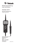
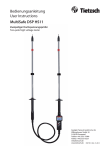
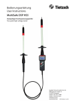
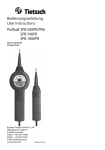
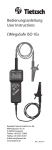
Bedienungsanleitung User Instructions MultiSafeDSP 4 Spannungs- und Durchgangsprüfer Voltage-Continuity Tester Rudolph Tietzsch GmbH & Co. KG Willringhauser Straße 18 58256 Ennepetal Germany T +49 2333-75989 F +49 2333-75257 [email protected] www.tietzsch.de DSP4_BA_7-09 1 2 3 4 5 6 7 8 9 1 2 3 4 5 6 7 8 9 Prüfelektroden LV-Anzeige (LEDs rot) ab 50 V / 120 V Anzeige von gefährlichen Spannungen 50 - 1000 V AC / 120 - 1500 V DC LED „Ω“ (grün): leuchtet bei Durchgang 0 ... 1999 kΩ (Schallgeber signalisiert Durchgang) LED „Pol-L1“: für Phase + Drehfeld Display (LCD) Taster HOLD: für Funktionen Messwert festhalten Taster Ω/V: Umschalt-Taster für Widerstands-/Spannungsmessung und Nullabgleich des kΩ-Bereichs Taster : Ein-Aus-Taster (manuell) und Funktionstest Handgriff Symbole auf dem Gerät Achtung! Bedienungsanleitung beachten! Zeichengenehmigung durch VDE-Prüfstelle EG-Konformitätskennzeichnung ED Einschaltdauer für Spannungsprüfung WEEE 2002/96 EG: Dieses Gerät darf nicht mit dem Hausmüll entsorgt werden. Bei Fragen zur Altgerät-Rücknahme wenden sie sich bitte an [email protected] 2 1. Anwendung Der MultiSafe DSP 4 ist ein zweipoliger, digital anzeigender Spannungsprüfer, zertifiziert nach DIN EN 61243-3 (VDE 0682 Teil 401), kombiniert mit einem Durchgangs-, Phasen-, Polaritäts- und Drehfeldprüfer. Mit diesem können Sie das Vorhandensein und die Höhe von Wechsel- oder Gleichspannung von 24 V bis 1000 V bei Frequenzen bis 4 kHz feststellen. Mit dem integrierten Durchgangsprüfer können Sie zusätzlich Widerstände im Bereich von 0 bis 1999 kΩ messen. Spannungsund Widerstandswerte werden digital auf einem LC-Display angezeigt. Zusätzlich signalisieren vier Leuchtdioden Spannung, Phase, Drehfeld, sowie eine Leichtdiode und ein Schallgeber Durchgang. Der MultiSafe ist durch seine hohe Schutzart (IP 65) auch bei Niederschlägen einsetzbar. 2. Sicherheitshinweise Sie haben sich für ein Gerät entschieden, dass Ihnen ein sehr hohes Maß an Sicherheit bietet. Bei bestimmungsgemäßer Verwendung gewährleistet er sowohl die Sicherheit der bedienenden Person als auch die des Gerätes. Um den sicherheitstechnisch einwandfreien Zustand zu erhalten und die gefahrlose Verwendung sicherzustellen, ist es unerlässlich, dass Sie vor dem Einsatz Ihres Gerätes diese Bedienungsanleitung sorgfältig und vollständig lesen und diese in allen Punkten befolgen. Hohe Sicherheit bietet das Gerät durch zwei Vorwiderstände unmittelbar hinter den beiden Prüfelektroden sowie zwei völlig unabhängige voneinander arbeitende Prüfsysteme: - LV Anzeige, die auch ohne Batterie vorhandene Spannung durch LEDs sicher anzeigt. - Digitalanzeige für exakte Prüfwerte. Für den Spannungsprüfer MultiSafe DSP 4 wurde von der VDE-Prüfstelle die Genehmigung zum Benutzen des VDE GS-Zeichens erteilt. Bitte beachten Sie folgende Sicherheitsvorkehrungen: Die Spannungsangaben auf dem MultiSafe DSP 4 sind Nennwerte. Der Spannungsprüfer darf nur in Anlagen mit dem angegebenen Nennspannungsbereich benutzt werden. Eine einwandfreie Anzeige ist nur im Tempera turbereich von - 10° C bis + 55° C sichergestellt. Gerät nur an den Handgriffen anfassen, um die Anzeige nicht zu verdecken und die Prüfelektro den nicht zu berühren. 3 Spannungsprüfer müssen kurz vor dem Einsatz auf Funktion geprüft werden. Führen Sie den Funktionstest durch und überprüfen Sie das Gerät an einer bekannten Spannungsquelle, z.B. 230 V-Steckdose. Fällt hierbei die Anzeige eines oder mehrerer Systeme aus, darf das Gerät nicht mehr verwendet werden. Die maximal zulässige Einschaltdauer des MultiSafe DSP 4 beträgt 2 min. Bei Ermittlung von Außenleitern und der Drehfeld richtung kann die Wahrnehmbarkeit der Anzeige beeinträchtigt sein, z.B. bei der Verwendung von isolierenden Körperschutzmitteln, bei ungünstigen Standorten wie Holztrittleitern oder isolierenden Fußbodenbelägen sowie bei ungünstigen Beleuch tungsverhältnissen und bei einem nicht betriebs mäßig geerdeten Wechselspannungssystem. Unbefugte dürfen den Spannungsprüfer nicht zerlegen. Spannungsprüfgeräte müssen trocken und sauber sein. 3. Inbetriebnahme 3.1 Batterie In Ihr Gerät ist bereits eine 9 V-Batterie nach IEC 6 F 22 bzw. 6 LR 61 eingesetzt. Der Batteriezustand wird durch das Batteriesymbol auf der LCD angezeigt, siehe Kapitel 8.1 Achtung! Beachten Sie vor der ersten Inbetriebnahme oder nach Lagerung Ihres Gerätes unbedingt das Kapitel 8.1. 3.2 Prüfen von Anzeige und Funktion (Eigentest) Nach DIN VDE 0105 Teil 1 müssen Spannungsprüfer, kurz bevor diese zum Prüfen auf Spannungsfreieheit genutzt werden, auf einwandfreie Funktion überprüft werden. Schritt 1 - Test der Anzeige Drücken Sie den Taster und halten diese gedrückt. Auf dem LC-Display leuchten alle Segmente, zusätzlich leuchten die Ω- und POL-LED sowie der Summer ertönt. Lassen Sie den Taster los, der Wert 0.00 ... 0.02 V wird angezeigt. Schritt 2 - Überprüfen der Leitung/Funktion Betätigen Sie den Taster Ω/V. In der Anzeige erscheint OL und MΩ. Halten Sie die beiden Prüfelektroden zusammen. Auf dem Display wird der Wert 000 ... 002 kΩ angezeigt. Gleichzeitig gibt der Schallgeber ein Signal ab und die grüne LED „Ω“ leuchtet. Hierdurch wird die Gesamtfunktion des Gerätes überprüft. Schritt 3 - Test der LV-Anzeige Überprüfen Sie die Funktion der LV-Anzeige (50 V-LED / 120 V-LED) an einer bekannten Spannungsquelle, z.B. 230 V Steckdose. Der geprüfte Spannungswert wird gleichzeitig auf der LCD angezeigt. 4 Achtung! Fällt bei der Eigenüberprüfung eine Anzeige auch nur teilweise aus oder wird keine Funktionsbereitschaft angezeigt, darf der Spannungsprüfer nicht mehr verwendet werden! 4. Messen und Prüfen 4.1 Allgemeine Hinweise Der Spannungsprüfer schaltet sich beim Anlegen einer Spannung ab 24 V automatisch ein. Um die Batterie zu schonen, schaltet sich das Gerät etwa 30 s nach der letzten Messung automatisch aus. 4.2 Spannung und Polarität prüfen Achtung! Die zulässige Einschaltdauer bei Spannungsprüfungen beträgt maximal 2 Minuten. Hinweis! Bei einpoligem Anlegen einer Prüfspitze an Spannung oder an ein statisch aufgeladenes Teil kann sich der Spannungsprüfer automatisch einschalten. Dieser Vorgang ist ohne Bedeutung. Nennspannungsbereich 24 ... 1000 V Setzen Sie die beiden Prüfspitzen mit sicherem Kontakt auf die Messstellen auf. Ab einer Spannung von 24 V schaltet sich das Gerät automatisch ein. Falls „Durchgangsprüfung“ eingeschaltet ist, schaltet es automatisch auf „Spannung prüfen“ um. Das Gerät wählt automatisch den Messbereich (siehe Technische Kennwerte), welcher dem anliegenden Spannungswert entspricht und zeigt die Spannung in „V“ auf dem LC-Display an. Achtung! Ab einer Spannung von 50 V / 120 V leuchtet die LV-Anzeige. Es liegt eine gefährliche Spannung an! Hinweis! Die LV-Anzeige (LEDs) bleibt auch bei leerer oder nicht vorhandener Batterie funktionsbereit. Sollte nur noch dieses Messsystem anzeigen bitte Punkt 3.2 beachten. Polarität anzeigen Die Art der Spannung wird durch die Symbole ~ und – dargestellt. Bei Gleichspannung: Liegt Minus an der mit „+“ gekennzeichneten Prüfspitze mit Anzeigeteil an, so erscheint das „-“ Vorzeichen. Liegt dort Plus an , so erscheint kein Vorzeichen vor dem angezeigten Wert. Spannungen über 1220 V AC/DC Bei Spannungen über 1220 V AC/DC erfolgt eine akustische Warnmeldung und blinkender Anzeigewert. Wechselspannungs-Messungen sind bis 1220 V zuverlässig. Sie sind durch „~“ vor dem Anzeigewert erkennbar. Spannungen mit einer Frequenz von über 2 kHz werden durch ein blinkendes Hz Zeichen angezeigt. Gleichspannungsmessungen können bis 1500 V zuverlässig durchgeführt werden. Spannungen kleiner 24 V Bei Spannungen unter 24 V muss das Gerät durch Drücken der Taster ein- bzw. umgeschaltet werden. 5 4.3 Phase und Drehfeldrichtung prüfen Der MultiSafe DSP 4 ist mit einer dreieckigen LEDAnzeige ausgestattet, um Phasen- und Drehfeldrichtungsprüfungen durchführen zu können. Diese Prüfungen funktionieren bei Nennspannungen ab 165 V (50 Hz) gegen Erde. Achtung! Bei diesen Prüfungen muss das Gerät an der Handhabe des Geräteteils fest umfasst werden (Bild unten). Hinweis! Es können isolierende Handschuhe getragen werden. Prüfungen können durch ungünstige Standorte wie Holztrittleitern oder stark isolierende Fußbodenbeläge und bei nicht betriebsmäßig geerdeten Wechselspannungssystemen beeinträchtigt werden. 4.3.1 Phasenprüfung Die Ermittlung des Außenleiters erfolgt durch Anlegen der Prüfspitze (+L1) an den Leiter. Wird „POL“ auf dem LC-Display angezeigt und leuchtet das Dreieck im Anzeigefeld, so ist der Leiter spannungsführend 4.3.2 Prüfen der Drehfeldrichtung Das Drehfeld zwischen zwei Phasen im geerdeten 230/400 V-Drehstromnetz (bis max. 690/1200V) wird durch Anlegen beider Prüfspitzen und Umfassen des Geräteteils wie folgt festgestellt: - Suchen Sie einpolig die Außenleiter (siehe Kap. 4.3.1). - Legen Sie beide Prüfspitzen an zwei Außenleiter an (Anzeige ca. 400 V). - Liegt die Phase L1 an der Prüfspitze mit Anzeige (+L1) und L2 an der Prüfspitze des Griffes, so leuchtet das Dreieck bei Rechtsdrehfeld. Leuchtet das Dreieck nicht, so liegt ein Linksdrehfeld vor. Hinweis! Falls 230 V statt 400 V angezeigt wird, ist möglicherweise der Neutralleiter kontaktiert. Eine einfache Kontrolle der Prüfung ist durch Tauschen der beiden Prüfelektroden möglich. 6 5. Messwerte „festhalten“ (HOLD) Durch Festhalten der Taste „HOLD“ wird der maximale Spannungswert auf dem Display „gespeichert“. Der Wert wird für ca. 30 s oder bis Sie die Taste „HOLD“ erneut drücken angezeigt. Durch erneutes Anlegen an eine Spannung wird die Hold-Funktion automatisch beendet. Hinweis! Wenn sich der Messwert für ca. 2 s nicht mehr ändert wurde der Maximalwert erfasst. 6. Widerstand und Durchgang prüfen Drücken Sie bei eingeschaltetem Gerät auf den Taster „Ω/V“. „OL“ und „MΩ“ erscheint auf der LCD. Setzen Sie die beiden Prüfelektroden mit sicherem Kontakt auf die Messstellen auf. Bei Widerstandswerten von 0 ... 10 kΩ wird der Messwert auf dem LCD in „kΩ“ angezeigt. Gleichzeitig leuchtet die grüne LED „Ω“ und der Schallgeber gibt Signal. Bei Widerstandswerten von 10 kΩ ... 1,999 MΩ wird der Messwert in „kΩ oder MΩ“ angezeigt. Gleichzeitig blinkt die LED „Ω“. Der Schallgeber gibt kein Signal. Bei Widerstandswerten > 2 MΩ geht die Anzeige in den Überlauf und „OL“ und „MΩ“ wird angezeigt. Die LED und der Schallgeber geben kein Signal. Funktion Messwerte „festhalten“ (HOLD) Solange Sie die Taste „HOLD“ gedrückt halten, können Sie den aktuell gemessenen Widerstandswert auf dem LC-Display „festhalten“. Nullabgleich Der Nullpunkt im Widerstandmessbereich kann bei Bedarf nachkalibriert werden: Halten Sie die beiden Prüfelektroden fest zusammen und halten Sie den Taster „Ω/V“ gedrückt bis im Display „CAL“ erscheint und die grüne LED Ω blinkt. Sobald 000 angezeigt wird und die LED Ω dauernd leuchtet, wurde die Kalibrierung erfolgreich beendet. Während des Vorganges wird ein Signal Ton erzeugt. Hinweis! Bei der Durchgangsprüfung ist der Pluspol der Messspannung, die mit +L1 gekennzeichnete Prüfspitze. Der Messstrom beträgt konstant 5 µA für 0 ... 10 kΩ ; 1µA für 10 ... 1999 kΩ . Wird in diesem Betriebsmodus eine Spannung größer oder gleich 24 V angelegt, schaltet das Gerät automatisch auf „Spannung prüfen“ um. 7 7. Technische Kennwerte Messgröße Messbereiche (automatische Bereichswahl) Auflösung U- 0,10 V ... 8,99 V 9,0 V ... 99,9 V 100 V ... 1500 V 0,01 V 0,1 V 1V U~ TRMS 1,0 V ... 99,9 V 100 V ... 1200 V U~¹) 15 V ... 99,9 V 100 V ... 499 V 0 ... 49 kΩ 50 ... 1999 kΩ _ 15 Hz ... 1,8 kHz 0,1 V 1V 500 V ... 1200 V R Frequenz Eigenbereich/ abweichung Messstrom 1 kΩ ›1,8 Hz ... ... 10 kHz ›1,8 Hz ... ... 4 kHz 5 µA 1 µA ±1,5 % +3 Digits ±1,5 % +3 Digits ±15 % +3 Digits ±5 % +2 Digits ¹) Effektivwert, Sinus Nennspannungsbereich: 24* ... 1000 V AC/1500 V DC *Auto on ab 24 V Nennfrequenzbereich: 15 Hz ... 10 kHz < 500 V, 15 Hz ... 4 kHz > 500 V Eingangswiderstand: 311 kΩ Strom Scheitelwert Is: 3,2 mA bei 1000 V Einschaltdauer: 2 Minuten Anzeige: 5 LEDs für Spannung, Durchgang, Phase und Drehfeldrichtung LCD Digitalanzeige 7-Segment-Ziffern, 2 Zeilen 0 ... 1999 Digit hintergrundbeleuchtet 3 Messungen/s Stromversorgung: 9 V-Blockbatterie IEC 6F22 Zink-Kohle oder IEC 6LR61 Alkali-Mangan oder entsprechender Akkumulator, mehrstufige Anzeige des Batteriezustandes Überspannungskategorie: CAT IV Stoßspannungsfestigkeit: >12 kV (1,2/50 µs) Prüfspannung: 6 kV EMV-Anforderungen: DIN-EN 61326 Betriebstemperaturen: -10 ... + 55°C Gehäuse: schlagfestes, staub- dichtes Kunststoff gehäuse mit unzerbrechlicher Anzeigeabdeckung Schutzart: IP 65 Verbindungsleitung: Gummischlauchleitung H07RN-F, 1 m Abmessungen: Prüfspitze mit Anzeigeteil 240 x 62 x 39 mm Gewicht: 270 g (inkl. Batterie) 8 8. Batterie 8.1 Batterieanzeige Der aktuelle Zustand der Batterie wird über die dreistufige Batterieanzeige im Display angezeigt. = Batterie voll = Batterie halb voll (noch viele Messungen möglich) = Batterie leer Die Hintergrundbeleuchtung wird automatisch deaktiviert, je nach Batterietyp können Sie in diesem Zustand noch 30 bis 100 Messungen durchführen. Achtung! Wenn das leere Batteriesymbol blinkt, sind keine Messungen mehr möglich, die Batterie muss dann sofort gewechselt werden. Das Gerät arbeitet mit einer 9 V-Blockbatterie IEC 6 F22 (Zink-Kohle) oder IEC 6 LR61 (AlkaliMangan). 8.2 Batterie austauschen Lösen Sie auf der Rückseite des Gerätes die Schraube zur Befestigung des Batteriefachdeckels und nehmen Sie den Deckel ab. Lassen Sie die Batterie mit CAT IV-Schutzhaube aus dem Batteriefach fallen und wechseln Sie die Batterie. Schnappen Sie hierzu die Batterieanschlusskontakte auf die neue 9 V-Batterie auf und setzen Sie die Batterie zusammen mit der CAT IV-Schutzhaube in das Batteriefach ein. Setzen Sie den Batteriefachdeckel wieder auf und schrauben diesen fest. Überzeugen Sie sich in regelmäßigen Abständen, dass die Batterie ihres Gerätes nicht ausgelaufen ist. Bei ausgelaufener Batterie müssen Sie den BatterieElektrolyt vollständig entfernen und eine neue Batterie einsetzen. Wenn Sie den Spannungsprüfer längere Zeit nicht benutzen, dann sollten Sie die Batterie aus dem Gerät nehmen. 9. Wartung Der Prüfball ist völlig wartungsfrei. Dennoch ist folgendes für den sicheren Betrieb zu beachten: Bewahren Sie Ihren Spannungsprüfer stets in trockenem und sauberem Zustand auf. Das Gehäuse können Sie mit einem mit Isopropanol (Alkohol) oder Seifenwasser befeuchteten Tuch reinigen. 9 10. Reparatur Eine Reparatur ist nur durch den Hersteller oder durch vom Hersteller ausdrücklich ermächtigte Werkstätten zulässig. Bei Beschädigung des Gerätes, Ausfall des Funktionstests nach Punkt 3.2 oder zur detaillierten Überprüfung/Kalibrierung wenden Sie sich bitte an: [email protected] oder senden Sie das Gerät mit Fehlerbeschreibung an den Hersteller (Adresse siehe Seite 1). 11. Zubehör Verlängerung/Adapter: Es dürfen nur aufschraubbare oder aufsteckbare Verlängerungen/Adapter DSP-S vom Hersteller verwendet werden. Für fest aufschraubbare Verlängerungen müssen beide Prüfspitzen des MultiSafe DSP mit Gewinde ausgestattet sein. Die Spitzen/Adapter dürfen nur verwendet werden, wenn sie auf dem Spannungsprüfer montiert sind. Sie sind vollständig und fest auf das Gerät zu stecken /zu verschrauben. Vor Spannungsprüfungen ist der Funktionstest (siehe Kapitel 3.2) mit montierten Spitzen durchzuführen. Vor der Spannungspüfung muss das Gerät mit Verlängerung sauber und trocken sein. Mehr Informationen erhalten Sie unter www.tietzsch.de. 10 User Instructions MultiSafeDSP 4 Voltage-Continuity Tester Rudolph Tietzsch GmbH & Co. KG Willringhauser Straße 18 58256 Ennepetal Germany T +49 2333-75989 F +49 2333-75257 [email protected] www.tietzsch.de DSP4_BA_7-09 1 2 3 4 5 6 7 8 9 1 2 3 4 5 6 7 8 9 Test electrodes LV indication (LEDs red) from 50 V / 120 V indication of hazardous voltage 50 - 1000 V AC / 120 - 1500 V DC LED „Ω“ (green): lights up during resistance measurements between 0 ... 5999 kΩ (acoustic signal signalizes continuity) LED „Pol-L1“ : for phase + rotating field Display (LCD) Button HOLD: function to recording values Button Ω/V: change-over switch for resistance and voltage measurements and zero balancing of the kΩ range Button : switch on/off (manual) and functions test Handgear Symbols on the instrument Attention! Observe user instructions! Mark of approval from VDE test authority Indicates EC conformity ED Duration time for voltage testing WEEE 2002/96 EG: This devices may not be disposed with the domestic waste. Please contact [email protected] regards the return of old devices. 12 1. Application The MultiSafe DSP 4 is a two-pole voltage tester with digital display. It complies with DIN EN 61243-3 (VDE 0682 part 401) and is provided with continuity and phase tester, polarity tester and phase sequence indicator. With this device you can determine the existence and the strength of AC and DC voltages within a range of 24 V to 1000 V at frequencies of up to 4 kHz. With the integrated continuity tester you can also measure resistances within a range of 0 to 1999 kΩ. Voltage and resistance values appear in digital format at the LCD. Additionally, 4 LEDs indicate voltage, phase, rotating field as well as one LED and one sound generator continuity. Due to its high protection category IP 65 the MultiSafe can be used in precipitation. 2. Safety Precautions You have selected an instrument which provides you with a high degree of safety. When used for its intended purpose, safety of the operator, as well as that of the instrument, is assured. In order to maintain flawless technical safety conditions, and to assure safe use, it is imperative that you read these operating instructions thoroughly and carefully before placing your instrument into service, and that you follow all instructions contained therein. The instrument provides a high degree of safety by means of two series resistors immediately behind the test electrodes as well as two absolutely independently working test systems. - LV Anzeige, die auch ohne Batterie vorhandene Spannung durch LEDs sicher anzeigt. - Digitalanzeige für exakte Prüfwerte. VDE test authorities have granted the application of the VDE GS-symbol for the MultiSafe DSP 4. Please observe the following safety precautions: The voltages indicated on the MultiSafe DSP 4 are rated voltages. The voltage tester may only be used in systems that are working within this rated voltage range. Faultless indication of display values is only guaranteed between -10°C and +55°C. Hold the instrument by its handles only to avoid covering the display or touching the test elecrodes. 13 Just before they are used, voltage testers need to be checked to ensure that they function correctly. Perform the function test and check the instrument at a known voltage source, e.g. a 230 V socket. If the display of one or several systems fails in the course of checking, then the device must not be used again. The maximum on-period of the MultiSafe DSP 4 is 2 minutes. With determination of phase conductors and phase sequence the perceptibility of the display may be impaired, e.g. when using insulating protective ge ars, in unfavourable locations, for example on wooden ladders or insulating floor coverings, as well as with unfavourable lighting conditions and in an improperly grounded a.c. voltage system. The voltage tester may not be dismantled by unauthorized personnel. Voltage testers must be kept dry and clean. 3. Putting into operation 3.1 Battery Your instrument is already supplied with a 9 V flat cell batter in accordance with IEC 6 F 22 or 6 LR 61. The battery status is indicated by a battery symbol on the LCD (see section 8.1). Attention! Please observe chapter 8.1 before initial startup or after your device has been in storage for a long time. 3.2 Testing correct display and function (Self-test) In accordance to DIN VDE 0105 part 1 voltage testers must be tested if they function correctly just before it is used for determining zero-potential. Step 1 – Test of the display Press and hold button . All display segments light up on the LCD, additionally, the Ω LED and POL-LED light up as well as a buzzer sound can be heard. Release button , the value 0.00 ... 0.02 V is indicated on the display. Step 2 – Checking the line / function Afterwards, actuate button Ω/V. OL and MΩ appear on the display. Hold the test electrodes together. The value 000 ... 002 kΩ appears on the display. At the same time, an acoustic signal is generated and the green LED “Ω“ lights up. Through this, the overall functions have been tested. Step 3 – Test of the LV indication Check the function of the LV indication (50 V LED / 120 V LED) at a known voltage source, e.g. a 230 V socket. At the same time, the determined voltage value is indicated on the LCD. Attention! If one of the displays fails during the self-test – even if only partial failure occurs – or if the instrument does not indicate a function standby, the voltage tester may not be placed into operation! 14 4. Measuring and testing 4.1. General information The voltage tester switches-on automatically when a voltage of at least 24 V is applied. In order to extend battery life the instrument switches-off automatically approximately 30 seconds after the last measurement. 4.2.Testing voltage an polarity Attention! The maximum allowable on-period for voltage testing is 2 minutes. Note! Maybe that the voltage tester switches-on automatically even when only one test probe is connected to voltage or to a statically charged object. But this has no significance. Nominal voltage range 24 ... 1000 V Securely contact the test probes with the test points. The instrument switches-on automatically at a voltage of at least 24 V. If the function „continuity testing” had been activated, the device switches automatically to „voltage testing”. The instrument automatically selects the measuring range that corresponds to the applied voltage (see Characteristic Values) and indicates the voltage “V” on the LC-display. Attention! The LV indication lights up at a voltage of at least 50 V / 120 V. A hazardous voltage is impressed. Note! The display of the LV indication (LEDs) even remains in working order when the battery is empty or when the device is not equipped with a battery. In case only this measurement system is indicating, please observe section 3.2. Indicating polarity The type of voltage is symbolized by the symbols ~ and -. Direct voltage: when minus is connected to the test probe designated with „+” and with display part, then the “-” leading sign appears. When plus is connected, then no leading sign appears left to the displayed value. Voltages > 1220 V AC/DC If a voltage of at least 1220 V AC/DC is applied, an acoustic warning signal is generated and the display value flashes. Alternating voltages of up to 1220 V can be reliably measured. They are identified with „~” left of the display value. Voltages with frequency of more than 2 kHz are indicated by the flashing Hz symbol. Direct voltage measurements of up to 1500 V can be performed reliably. Voltages < 24 V For voltages of less than 24 V the device must be switched on or over with button . 15 4. Measuring and testing 4.1. General information The voltage tester switches-on automatically when a voltage of at least 24 V is applied. In order to extend battery life the instrument switches-off automatically approximately 30 seconds after the last measurement. 4.2.Testing voltage an polarity Attention! The maximum allowable on-period for voltage testing is 2 minutes. Note! Maybe that the voltage tester switches-on automatically even when only one test probe is connected to voltage or to a statically charged object. But this has no significance. Nominal voltage range 24 ... 1000 V Securely contact the test probes with the test points. The instrument switches-on automatically at a voltage of at least 24 V. If the function „continuity testing” had been activated, the device switches automatically to „voltage testing”. The instrument automatically selects the measuring range that corresponds to the applied voltage (see Characteristic Values) and indicates the voltage “V” on the LC-display. Attention! The LV indication lights up at a voltage of at least 50 V / 120 V. A hazardous voltage is impressed. Note! The display of the LV indication (LEDs) even remains in working order when the battery is empty or when the device is not equipped with a battery. In case only this measurement system is indicating, please observe section 3.2. Indicating polarity The type of voltage is symbolized by the symbols ~ and -. Direct voltage: when minus is connected to the test probe designated with „+” and with display part, then the “-” leading sign appears. When plus is connected, then no leading sign appears left to the displayed value. Voltages > 1220 V AC/DC If a voltage of at least 1220 V AC/DC is applied, an acoustic warning signal is generated and the display value flashes. Alternating voltages of up to 1220 V can be reliably measured. They are identified with „~” left of the display value. Voltages with frequency of more than 2 kHz are indicated by the flashing Hz symbol. Direct voltage measurements of up to 1500 V can be performed reliably. Voltages < 24 V For voltages of less than 24 V the device must be switched on or over with button . 15 4.3 Testing phase and phase sequence The MultiSafe DSP 4 is equipped with a triangular LED display in order to perform phase and phase sequence tests. These tests can be performed at a nominal voltage of at least 165 V (50 Hz) to earth. Attention! When performing these tests the device must be hold closely at the handle bar of the device (see picture below). Note! You may wear insulating gloves when performing the tests. Tests can be impaired by unfavourable locations, for example on wooden ladders or insulating floor coverings, as well as in improperly grounded a.c. voltage systems. 4.3.1 Phase test Determination of the outer conductor occurs by applying the test probe (+L1) to the conductor. When “POL” appears on the LCD and at the same time the triangle in the display field lights up, then conductor is live. 4.3.2 Testing phase sequence The rotating field between two phases in a grounded 230/400 V 3-phase system (up to max. 690/1200V) is determined by applying both test probes and simultaneously grasping the device parts, the way it is described in the following section: - Identify unipolar the outer conductors (see section 4.3.1). - Apply both test probes to two outer conductors (display: approx. 400 V). - When phase L1 is applied to the test probe with display (+L1) and when L2 is applied to the test probe of the handle, then the triangle lights up in a clockwise rotating field. When the triangle does not light up, the direction of rotating field is counterclockwise. Note! If 230 V instead of 400 V is displayed, the neutral conductor may have been contacted. A simply control of the test is possible when the test probes are exchanged. 16 5. “Hold” test results (HOLD) The maximum voltage value can be „stored“ on the display when keeping pressed button „HOLD“. The value is recorded for approx. 30 seconds or until you press button „HOLD“ again. The Hold-function is stopped when again a voltage is impressed. Note! When the measured value does not vary for 2 sec, then the maximum value is recorded. 6. Testing resistance and continuity When the instrument is switched-on, press button „Ω/V“. “Ol” and “MΩ” appear on the LCD. Securely contact the measuring points with the test probes. Resistance values 0 ...10 kΩ the measured value is indicated on the LCD in „kΩ“.The green LED “Ω“ lights up at the same time, and an acoustic signal is generated. Resistance values 10 kΩ ...1,999 MΩ the measured value is indicated on the LC-Display in „kΩ“ or in „MΩ“. The LED “Ω“ lights up at the same time, and no acoustic signal is generated. Resistance values > 2 MΩ the display passes to overflow and „OL” and “MΩ“ appear on the display. The LED does not light up and no acoustic signal is generated. Function to “hold” measured values (HOLD) As long as you keep pressed button „HOLD“ you can “record” the latest measured resistance value on the LC-display. Zero balancing The zero point in the resistance measuring range can be recalibrated if necessary: Hold the test electrodes together and press and hold button „Ω/V“ until “CAL” appears in the display and the green LED Ω flashes. When 000 is indicated and the LED Ω lights up continuously, then calibration has been carried out sucessfully. During this process an acoustic signal is generated. Note! During continuity tests, the plus pole of the measuring voltage is located at the test probe designated with +L1. The measuring current has a constant value of 5 μA for values of 0 ... 10 kΩ; 1 μA for 10 ... 1999 kΩ. When in this operating mode a voltage of 24 V or more is impressed, then the device switches automatically to „voltage testing”. 17 7. Characteristic values Measurement Measuring ranges (auto-ranging) Resolution U- 0,10 V ... 8,99 V 9,0 V ... 99,9 V 100 V ... 1500 V 0,01 V 0,1 V 1V U~ TRMS 1,0 V ... 99,9 V 100 V ... 1200 V U~¹) 15 V ... 99,9 V 100 V ... 499 V 0 ... 49 kΩ 50 ... 1999 kΩ _ 15 Hz ... 1,8 kHz 0,1 V 1V 500 V ... 1200 V R Frequency Intrinsic range/ error measuring 1 kΩ ›1,8 Hz ... ... 10 kHz ›1,8 Hz ... ... 4 kHz 5 µA 1 µA ±1,5 % +3 digits ±1,5 % +3 digits ±15 % +3 digits ±5 % +2digits ¹) effective value; sinus Nominal voltage range: 24* ... 1000 V AC/1500 V DC *Auto on from 24 V Nominal frequency range: 15 Hz ... 10 kHz < 500 V, 15 Hz ... 4 kHz < 500 V Input resistance: 311 kΩ Current (Peak value Is): 3,2 mA at 1000 V On-period: 2 minutes Display: 5 LEDs for voltage, continuity, phase and phase sequence LCD digital display 7-segment-figure, 2 lines 0 ... 1999 digit background lightning 3 measurment/s Power supply: 9 V block battery IEC 6F22 zinc-carbon or IEC 6LR61 alkaline manganese or corre sponding accumulator, multi-stage display of battery status Surge voltage category: CAT IV Impulse withstand voltage: >12 kV (1,2/50 µs) Test voltage: 6 kV EMV-requirements: DIN-EN 61326 Operating temperature: -10…+55°C Casing: impact resistant, dustproof plastic casing with unbreakable display cover Protection category: IP 65 Interconnection line: rubber-insulated flexible cable H07RNF, 1m Dimensions: test probe with display part 240 x 62 x 39 mm Weigth: 270 g (incl. battery) 18 8. Battery 8.1. Battery indication The latest battery status is symbolised by a threestage battery indicator. = filled battery = half-empty battery (still many measurements possible) = flat battery The background lightning switches off automatically, depending on type of battery you still can perform at least 30-100 measurments. Attention! When the flat battery symbol flashes, then no more measurements can be performed and the battery has to be replaces immediately. The device requires a 9 V block battery IEC 6 F22 (zinc-carbon) or IEC 6 LR61 (alkaline manganese). 8.2 Replacing the battery Loosen the screw at the back of the instrument which secures the battery compartment lid, and remove the lid. Let the battery drop out of the battery compartment with its CAT IV protection cover and exchange it. Therefore, snap the battery contacts onto the 9 V flat cell battery and insert the battery together with the CAT IV protection cover into the battery compartment. Put the lid back on the battery compartment and screw it tight. Regularly make sure that the battery of your device does not leak. In case it does, you have to replace the electrolyte completely and insert a new battery. In case of a long storage period take the battery out of the device. 9. Maintainance The Prüfball is absolutely maintainance-free. Nevertheless, observe the following information in order to maintain safe operation: Always keep the voltage tester dry and clean. The housing can be cleaned with a cloth dampened with alcohol (isopropyl) or soapy water. 19 10. Repair Repair is only allowed by the manufacturer or explicitly authorised repair shops. In case of damages on the device or failure of the function test according to section 3.2 or for detailed inspection/calibration, please contact: [email protected] or send the device and a describtion of failure back to the manufacturer (address see page 1). 11. Accessories Extensions/Adapter: Only screwable or attachable extensions/adapters DSP-S that are provided by the manufacturer may be used. To use securely compact screwable extensions both test probes of the MultiSafe DSP must be provided with thread. Extensions/adapters may only to be used, when mounted on the voltage tester. They need to be attached/screwed completely and securely to the DSP. Perform the fuction test with mounted extensions (see section 3.2) before starting voltage testing. The device with extensions has to be clean and dry before start voltage testing. Further information are available at www.tietzsch.de 20