1
Wi
z
byPocketNeur
obi
cs
Bio-Signal Acquisition since 2000
USER MANUAL
v1.2 - first draft
v1.3 - second draft
- added USB & concurrent wireless transport mode
- added E/H/W/N Wiz to product suite
Quick Start
•
•
•
•
•
•
•
•
•
Install PC Application (BioExplorer, BioEra etc) - needs to be latest version, see copy on CD
plug Q/E/H-wiz into USN port and allow Windows to search for Pocket Neurobics driver in it's
on-line repository
or, for W/N-wiz, plug PN wireless dongle into USB port
as part of the Windows driver installation procedure, note the COM port number assigned to
the Pocket Neurobics device by Windows
only if driver installation fails, try the manual driver executable on the PN CD under 'utilities'
transfer illustrative BioExplorer and BioEra designs into respective directories on your PC
transfer media resources, video and audio files, into respective directories on your PC
open the PC Application, go to Device Configuration, enable the "PN Wiz" driver, and
configure it for the COM port assigned by Windows
open the illustrative design "Wiz_Test"
With successful installation, the Application should show the Wiz's start-up test sequence for the seconds
after it is powered on.
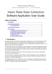
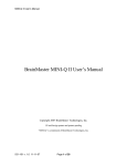
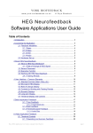
Feature Set
FeatureSet
Wiz Model:
Modes
Maximum sampling rate per slot
4 slots
2 slots
EEG/ECG/EMG/SCP
NIR/PIR/Pulse
NIR
Wireless &/or USB
Wireless only (8 wireless channels, 5m range)
EEG 21-ch Cap Interface & Control
Real-time 8-LED display of signal on Slot 1
24-bit resolution
16-bit resolution
DC-coupled (under User control)
Linking of Reference electrodes (user control)
Auto-baselining of HEG
Auto detection of Headband connection
Auto configuration of Slots for AC, DC signals
Detection of electrode lead-off
Q
E
0..4
512sps
X
X
X
X
X
X
0..3
0..2
0..3
0..2
512sps 128sps 512sps 128sps
X
X
X
X
X
X
X
X
X
X
X
X
X
X
X
X
X
H
X
X
X
X
X
X
X
X
W
X
X
N
X
X
X
X
X
X
X
X
X
X
X
Detection of poor signal
X
X
Vibration when signal quality changes
X
Remembers configuration
X
X
Self-test at startup
X
X
Signal Generator Mode
X
X
Firmware Upgradeable
X
X
Failsafe Mode
X
X
---------------------------------------------------------------------------------
X
X
X
X
X
X
X
X
X
X
X
X
X
X
X
X
X
X
X
1. Overview
The Wiz is a bio-signal acquisition device. The devices in the series capture bio-signals such as eeg and
blood oxygenation measures and forwards them via USB or wireless to an Application running on a PC which
has a Wiz driver to correctly interpret the signals being sent. The Wiz will typically be used as an element in a
bio-feedback training system.
In this manual, the following terms are used:
- "Modality": the type of bio-signal being acquired - eeg, emg, ecg, scp, nIR, pIR, and pulse oximetry
are modalities
- "Channels": the number of channels of each modality. For example 2 channel nIR can be carries
over 4 transport slots of the Q-wiz.
- "Transport Slot": the total number of Channels of various modalities that can be transported from
the Device to the PC.
- "Mode": the Mode of a device indicates its current configuration - the number of slots transported,
the sampling rate of those slots, and gain or amplification of each slot.
- "sps": samples per second, or how fast the bio-signal is samples. EMG needs a fast sampling rate,
whereas the blood oxygenation modalities can use a much slower sampling rate and thus use less of the
PC's processing resources.
There are five products currently defined in the Wiz product suite:
• Q-wiz: 2/4ch EEG/hHEG, usb/wireless, with eeg cap interface, implementing Modes 1..4
• Q for mini-Quantitative Assessment
• E-wiz: 2ch EEG, usb/wireless, implementing Modes 1..3
• E for EEG
• H-wiz: 2ch HEG, usb/wireless , implementing Modes 1..2
• H for HEG
• W-wiz: 2ch EEG wireless, implementing Modes 1..3
• W for wireless
• N-wiz: 2ch HEG wireless, implementing Modes 1..2
• N for nIR HEG
Applications supporting the Wiz suite are:
- BioExplorer (www.cyberevolution.com)
- BioEra (www.bioera.net - future)
The Wiz suite flexibly supports 1 to 4 transport slots. The modalities in those slots fall into two categories:
(i)AC (alternatibg current) signals:
• EEG, elecroencephalography, 1 to 4 chanels
• SCP, slow cortical potentials, 1 to 4 channels
• ECG, electrocardiography, 1 to 4 chanels, and
• EMG, elecromyography. 1 to 4 channels.
(ii) DC (slowly varying Direct Current) signals:
• nIR HEG, near infrared hemoencephalography , one or two channels
• pIR HEG, passive infrared hemoencephalography, one channel
• pulse oximeter sensing the pulse rate
EEG, SCP, ECG, and EMG all use the same silver or silver/silver-chloride electrode interface, whereas nIR
and pIR HEG blood oxygenation sensors use special headbands. The nIR HEG sensor input can also accept
a pulse oximeter input.
The Q-Wiz supports all modalities and up to 4 slots, whereas the E-wiz and the P-wiz support the AC
modalities, and the H-wiz and the N-wiz sport DC modalities, and the latter four devices support 2 slots.
Wiz devices automatically detect when a headband or finger sensor is connected and reconfigure
accordingly. When only one modality is used, it will appear on slot 1. For devices that support both AC and
DC modalities, namely the Q-wiz, when no headbands or finger sensors are connected slots will default to
AC - ie 2 or 4 channels of EEG etc.
The PC Application will automatically detect which modality is assigned to which slot and adjust accordingly.
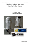
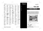
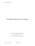
The Q-wiz supports all Modes and other devices in the suite support Modes 1..3 or Modes 1..2. The mapping
of Modality into transport slot changes according to which headband or finger sensor is connected, and which
Mode is selected:
Mode
Slot:
Slot1
Slot2
Slot3
Slot4
<Mode 1> 32sps - used for HEG (and EEG protocol processing - future)
<Mode 2> 128sps - Hi resolution EEG and HEG
<Mode 3> 512sps - EMG, ECG and SCP (and EEG if mixed modalites)
---------------------------------------------no headband sensed
EEG1 EEG2
nIR sensed
NIR1 NIR2*
nIR & pIR sensed
NIR1 PIR1
pIR sensed
PIR1 EEG1
PULS sensed
PULS1 EEG1
pIR & PULS1 sensed
PULS1 PIR1
---------------------------------------------<Mode 4> 256sps 4ch - mixed modes
---------------------------------------------no headband sensed
EEG1
nIR sensed
EEG1
nIR & pIR sensed
EEG1
pIR sensed
EEG1
PULS sensed
EEG1
pIR & PULS sensed
EEG1
EEG2
EEG2
EEG2
EEG2
EEG2
EEG3!
EEG3
NIR1
NIR1
EEG3
EEG3
Oxi1
EEG4
NIR2
PIR1
PIR1
Oxi1
PIR1
All devices also have a Mode 0, or Program Mode, which is selected to allow firmware updates, or, in the
case of wireless operation. to allow the PC to send Commands to the device (see section on Commanding
the device).
The Q/E/H-wiz can operate wirelessly or by direct USB connection. The P/N-wiz operate wirelessly only.
Wireless operation requires a PN wireless dongle connected to a USB port. Devices that operate either
wirelessly or by direct USB connection will automatically choose direct USB connection when a direct USB
connection is recognised ("enumerated").
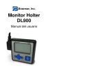
2. Buttons
All units have a Mode button. A short press sequences thru the available Modes. Mode is indicated by a
blinking green light. For Mode 1, the light blinks once. For Mode 0, or Program Mode, the light does not blink.
Modes are consistent across models. Mode 2 on the Q-wiz has the same attributes as Mode 2 on the E-wiz.
But not all models support all modes.
The Mode button also serves as a 'Signal Good' indication. This indication is an assessment of the quality of
signal on all active slots. When the signal is judged as good then the Green light is mostly on and blinks off. If
the signal cannot be judged Good, then the green light is off and blinks on.
On the Q-wiz, a long press of the Mode button activates the EEG Cap interface at which time the 8-LED
indicator reports the status of the Cap multiplexer.
All models have a second button which controls key functions of the active modality. For
EEG/ECG/EMG/SCP modalities, the Link/Freeze button toggles a link between the two reference electrodes
and also toggles whether the DC (direct current) component of the signal is removed or not. A short press of
the button toggles the link action, with a green light indicating that the references are currently linked. A long
press (>2sec) toggles whether the DC component is removed from the signal or whether the DC is not
removed ("frozen") which is indicated with a blue light. DC-coupling is preferred for ECG and SCP signal
sampling and should be used with Ag/AgCl electrodes.
Some unit shave a Power-On button and some not. If there is not a Power-On button, then the unit can be
de-powered by removing the USB cable (or switching off at a USB mini-hub with a power switch), or by
placing the unit in Program Mode (Mode 0).
Q-wiz:
• Mode button (green):
• short press, sequences thru Modes
• long press, activates the Q-menu and the Cap
interface
• pressed at power-up: enter fail-safe mode. Operates
with base feature set. Mode for recovery should
firmware become corrupted.
• Link (green) & Freeze (blue) button:
• short press, controls linking of EEG references, and
initiates nIR/pIR/pulse HEG baseline search.
• in Mode 0 and wireless transport,
increments rf channel (in USB Transport,
use Application to change wireless channel
if required)
• in Mode 0 and USB transport, toggles
between USB transport only and USB and
wireless transport concurrently (Transport
LED blinks with wireless channel number
when wireless is active)
• long press, controls freezing and unfreezing EEG
DC removal
• pressed at power-up: initiates Signal Generator
mode
• there is no Power On button for the Q-wiz.
• both Mode & Link Buttons together
• to exit Signal Generator Mode (or simply remove the
power from the unit & re-start)
• when in Q-menu mode, @ "Program Mode",
pressing the Link and Mode button enters/exits
programming of the User-defined switching of the
Cap (see section of the Q-menu).
E-wiz:
• Mode button (green):
• short press, sequences thru Modes
•
pressed at power-up: enter fail-safe mode. Operates with base feature set. Mode for
recovery should firmware become corrupted.
•
Link (green) & Freeze (blue) button:
• short press, controls linking of EEG references
• in Mode 0 and wireless transport, increments rf channel (in USB Transport, use
Application to change wireless channel if required)
• in Mode 0 and USB transport, toggles between USB transport only and USB and
wireless transport concurrently (Transport LED blinks with wireless channel number
when wireless is active)
•
•
•
long press, controls freezing and unfreezing EEG DC
removal
pressed at power-up: initiates Signal Generator mode
Power On Button
• toggles normal operation and power off
H-wiz:
• Mode button (green):
• short press, sequences thru Modes
• pressed at power-up: enter fail-safe mode.
Operates with base feature set. Mode for
recovery should firmware become corrupted
• Calibrate (green) button:
• short press, initiates nIR/pIR/pulse HEG
baseline search for nominal value of 100
• in Mode 0 and wireless transport,
increments rf channel (in USB
Transport, use Application to change
wireless channel if required)
• in Mode 0 and USB transport, toggles
between USB transport only and USB
and wireless transport concurrently
(Transport LED blinks with wireless
channel number when wireless is
active)
• pressed at power-up: initiates Signal Generator mode
• Power On Button
•
toggles normal operation / power off
W-wiz:
• Mode button (green):
• short press, sequences thru Modes
• pressed at power-up: enter fail-safe mode. Operates with base feature set. Mode for
recovery should firmware become corrupted.
• Link (green) & Freeze (blue) button:
• short press, controls linking of EEG references
•
in Mode 0 and wireless transport, increments rf channel (in USB Transport, use
Application to change wireless channel if required)
• in Mode 0 and USB transport, toggles between USB transport only and USB and
wireless transport concurrently (Transport LED blinks with wireless channel number
when wireless is active)
•
•
•
long press, controls freezing and unfreezing EEG DC removal
pressed at power-up: initiates Signal Generator mode
Wireless Channel button:
• increments wireless channel number when in Mode 0 (Program Mode). Sequences
thru channels 1..8
•
Power On Button
•
toggles normal operation and power off
N-wiz:
• Mode button (green):
• short press, sequences thru Modes
• pressed at power-up: enter fail-safe
mode. Operates with base feature set.
Mode for recovery should firmware
become corrupted.
•
•
Calibrate (green) button:
• short press, initiates nIR/pIR/pulse HEG
baseline search for nominal value of 100
• in Mode 0 and wireless transport,
increments rf channel (in USB
Transport, use Application to change
wireless channel if required)
• in Mode 0 and USB transport, toggles
between USB transport only and USB
and wireless transport concurrently
(Transport LED blinks with wireless
channel number when wireless is
active)
pressed at power-up: initiates Signal Generator mode
•
Wireless Channel button:
• increments wireless channel number when in
Mode 0 (Program Mode). Sequences thru
channels 1..8
•
Power On Button
• toggles normal operation and power off
3. LED Indicators
Q-wiz:
TRANSMIT {blue):
- On Steady: sending to Application via USB
- On Blink: sending wirelessly
- Off Blink: not transmitting to Application (ie Program Mode)
- Blink: wireless channel number
MODE/GOOD (green):
- On: no EEG lead off, and/or nIR full signal strength, and/or pIR valid reading
- Off: EEG lead off, or nIR not full strength, or pIR reading out of range
- Blink: Mode 0/1/2/3/4 = Program/32sps(2ch)/128sps(2ch)/512sps(2ch)/256sps(4ch)
LINK (blue/green):
- Blue On: EEG baseline frozen (DC coupled)
- Blue Off: DC removal - EEG low frequency response ~0.2Hz
- Green On: EEG References linked - only one Reference electrode required
- Green Off: EEG References independent - two References required for 2 eeg channel operation
HEG (yellow):
- On: when nIR, pIR or Oxi headband sensed
- Off: no headband sensed, all 2/4 channels used for EEG
- Blink: when nIR/pIR/pulse baseline search for nominal value of 100 is under way
- Fast Flash: indicates that User Defined configuration of the Cap is currently being programmed
E-wiz:
TRANSMIT {blue):
- On Steady: sending to Application via USB
- On Blink: sending wirelessly
- Off Blink: not transmitting to Application (ie Program Mode)
- Blink: wireless channel number
MODE/GOOD (green):
- On: no EEG lead off
- Off: EEG lead off
- Blink: Mode 0/1/2/3 = Program/32sps(2ch)/128sps(2ch)/512sps(2ch)
LINK (blue/green):
- Blue On: EEG baseline frozen (DC coupled)
- Blue Off: DC removal - EEG low frequency response ~0.2Hz
- Green On: EEG References linked - only one Reference electrode required
- Green Off: EEG References independent - two References required for 2 eeg channel operation
H-wiz:
TRANSMIT {blue):
- On Steady: sending to Application via USB
- On Blink: sending wirelessly
- Off Blink: not transmitting to Application (ie Program Mode)
- Blink: wireless channel number
MODE/GOOD (green):
- On: nIR full signal strength, and/or pIR valid reading
- Off: nIR not full strength, or pIR reading out of range
- Blink: Mode 0/1/2 = Program/32sps(2ch)/128sps(2ch)
CALIBRATE (blue):
- On: when nIR, pIR or Oxi headband sensed
- Off: no headband sensed, sends test signal to PC Application
- Blink: when nIR/pIR/pulse baseline search for nominal value of 100 is under way
W-wiz:
BLUE:
- On: EEG baseline frozen (DC coupled)
- Off: DC removal - EEG low frequency response ~0.2Hz
- Blink(Mode 0 only): wireless channel number
GREEN:
- On: EEG References linked - only one Reference electrode required
- Off: EEG References independent - two References required for 2 eeg channel operation
- Blink: Mode 0/1/2/3 = Program/32sps(2ch)/128sps(2ch)/512sps(2ch)
N-wiz:
BLUE:
- On: when nIR, pIR or Oxi headband sensed
- Off: no headband sensed, sends test signal to PC Application
- Blink: when nIR/pIR/pulse baseline search for nominal value of 100 is under way
- Blink (Mode 0): wireless channel number
GREEN:
- On: nIR full signal strength, and/or pIR valid reading
- Off: nIR not full strength, or pIR reading out of range
- Blink: Mode 0/1/2 = Program/32sps(2ch)/128sps(2ch)
4. Connecting to PC: Wireless and USB Transport
All models can transmit wirelessly. The W-wiz and the N-wiz are exclusively wireless. The Q/E/H-wiz can
transmit either wirelessly or directly via USB cable. The Q/E/H-wiz can also transmit both directly via USB
cable and wirelessly.
The Q-wiz can be powered from a normal USB port or by a "USB Portable Power" battery. In the case of the
latter, the Q-Wiz will automatically recognise that it does not have a USB connection and start to transmit
wirelessly. A PN proprietary dongle is required to receive the wireless signal.
The E-wiz and the N-wiz can be powered from either a USB port or 2x AA batteries placed inside the unit.
The batteries are not needed for USB operation.
The Q/E/H-wiz will default to direct USB communication if it is sensed that the power is derived from a USB
port. If not, they will transmit wirelessly. No manual intervention is required.
The W-wiz and the N-wiz operate from a single AAA battery inside the unit.
In cases where the computer is slow to enumerate the Q-wiz when connected, then the Q-Wiz may decide
that it is not connected to a USB port and begin transmitting wirelessly. Unplugging the unit and re-inserting
should have it enumerate correctly. If this happens persistently then the Q-wiz can be started in fail-safe
mode (see below) which grants a longer period for USB enumeration.
Concurrent Wireless and USB Transport
For the Q/E/H-wiz, when in USB Transport and Program Mode, a short press of the "Link" button will toggle
between having USB Transport only (the blue "Transmit" LED will be on steady), and having both USB and
Wireless Transport concurrently (signified by the blue "Transmit" LED being mostly on and blinking off). This
dual mode allows "training room" scenarios whereby USB connection is used to communicate with the PC at
each training seat, and wireless communication is used to a central control position which can scan the
progress of each training seat, or select one for closer monitoring. This setting is remembered from session
to session, but note that wireless operation can cause interference to other devices operating wirelessly each device will need its own wireless channel.
Changing Wireless Channels
When multiple Wiz's are operating in close proximity, each must have a separate wireless channel. There are
eight wireless channels available.
When in Wireless Transport (ie battery powered)
• the wireless channel number is incremented by choosing Mode 0 (Program Mode), then a _short_
press of the "Link" button
• the PC Application cannot command a change to the wireless channel
In USB transport mode
• the Application may have the ability to change wireless channels of the Wiz, and if so,
• the wireless channel number can be changed either in Program Mode (Mode 0) or in the Operating
Modes.
A new wireless channel number is remembered from session to session.
Separately, the PN wireless dongle needs to be set to the same wireless channel as that of the Wiz. That is,
the wireless dongle needs to be blinking at a rate the same as the Wiz. When the PN wireless dongle is
successfully receiving a signal, it's green LED is on and blinks off. The wireless channel of the dongle can be
changed either by _short_ presses of its button, or by commands from the PC Application if the Application
has that ability.
5. Modes
A _short_ press of the Mode button will change modes.
There are five Modes:
• Mode 0
• Program Mode, for uploading upgrades, interrogating version numbers etc
• Mode 1
• two transport slots at 32sps sampling rate: low transmission rates to minimise burden on PC
processor
• recommended for HEG & SCP only, not suited for use with EEG, EMG or ECG
• Mode 2
• two slots at 128sps sampling rate: most sensitive and low rates to minimise burden on PC
processor
• recommended for EEG and SCP
• Mode 3
• two slots at 512sps sampling rate for high bandwidth, 4x lower sensitivity
• recommended for ECG/EMG/SCP
• Mode 4 (Q-wiz only)
• four slots at 256sps sampling rate, high sensitivity
• recommended for 4 channel EEG, or mixed modalities
Mode changes are signified to the PC Application automatically, and the Application's interface will
reconfigure in sympathy. For some changes, like changing from 2-slot modes to 4-slot mode, the
Application's input may need to be manually reconfigured. Note that the Source Objects of the BioExplorer
Application have the ability to auto detect the modality of incoming signals such that if there is one Source
Object configured for EEG and another for HEG, then BioExplorer will automatically connect the correct
Source object to correct incoming stream. It does this on the fly.
Further, where there is a single channel of a single modality, then it will always appear on on the first input to
the Application, that is, Slot 1. Thus single channel protocol designs can assume the input is always the first
input.
6. EEG Electrode Interface
The Q-Wiz can operate as a single channel eeg, 2-channel eeg, 3-channel eeg, or 4-channel eeg. The E/Wwiz can operate as single or two channel eeg. If using EEG, EEG Channel 1 must be one of the channels
being used, however there are no constraints on which other channels are used. A Ground connection
("gnd") is also required for all EEG configurations. Thus the minimum arrangement for EEG use is three
elecrodes: 1+, 1-, and gnd.
The Wiz is a 24-bit resolution, directly coupled device. However the default mode of operation is to slowly
remove the DC component of the EEG so the signal does not wander and potentially move out of range of
the PC Application. This virtual High Pass Filter is set at about 0.2Hz. A _long_ press of the "Link/Freeze"
button will override DC removal, and a blue LED will light to signify that the DC-removal is now frozen
(_blue_ for _frozen_) and the amplifier will then act as a true DC-coupled device. Freezing the DC removal
operation is used with SCP and ultra-low frequency EEG modalities. Another long press will re-activate DCremoval and extinguish the blue LED. Freeze state is not remembered and will need to be set each time the
unit is powered on.
The amount of DC-offset removal can be remembered by the Wiz, allowing the eeg to settle faster when next
powered on. Offsets are grabbed at the time of freezing the eeg with a long press of the Freeze button.
A _short_ press of the "Link" button will electrically join the two Reference electrodes (1- and 2-) adjacent to
the Link button and a Green LED will light to signify that the references are linked. Another short press will
unlink and extinguish the Green LED. (_green_ for _link_). Linking of electrodes is typically used for
assessment procedures. Link state is remembered - the device will power-up in the state previously set.
For the Q-wiz, EEG channels 3 and 4 do not have their own separate reference electrode. EEG Channel 3
uses 1- as its reference and EEG Channel 4 uses 2- as its reference. If the green "Link" light is on, then all
four electrodes are sharing a common reference and only one reference electrode need be connected to the
body, although typically two reference electrodes are still used, one to each ear-lobe.
7. HEG Interface
The Q/H/N-wiz senses when a HEG (either nIR, pIR, or pulse) headband is connected. The "HEG" LED will
begin to flash, signifying that the unit is adjusting the signal to it's nominal value of 100. Once the nominal
value is found, the device automatically Freezes the baseline and the "HEG" LED stops flashing and
becomes steady on. The Wiz is then ready for training.
Note that the unit will attempt to find the nominal value whether the headband is on the head or not, so if a
false nominal value has been set, then a _long_ press of the "Calibrate" or "Link" button will initiate a new
search. Nominal values are found after 5 to 15 seconds of searching.
The offset required to establish the nominal value of 100 is remembered allowing HEG to settle faster next
time it is powered-on. Offsets are grabbed at the time a nominal value of 100 is achieved. These offset
values will then be saved to memory when there is either a mode change or a short press of the Link/Freeze
button. For both nIR and pIR HEG, should the limits of the range of reading be exceeded, then a search for
the nominal value of 100 is automatically re-started.
If in a 2-slot mode (ie Mode 1, 2, or 3) and just one headband is in use, either pIR or nIR, then the signal will
appear on Slot 1. This means that changing from pIR to nIR modality is as simple as changing headbands no reconfiguration of the Wiz or PC Application is required.
The Wiz supports 2-ch nIR Headbands. If the Wiz senses that the current headband supports only one nIR
channel, then it substitutes the Infrared component of the nIR1 signal on the nIR2 slot. This IR signal can be
used to gauge the quality of the nIR1 signal, and can be used by the application to derive the Pulse Rate
from the nIR signal, for say HRV training.
8. Other Sensors
Nellcor compatible SpO2/Pulse Oximeters can interface to the Q/H-wiz via an adaptor. The adaptor allows
the sensor to be plugged into the nIR HEG socket on the Wiz. Pulse Oximeters would generally be used to
obtain the pulse bioSignal. Pulse Rate and Heart Rate Variability training can be based on this signal.
Thermocouples can be used to measure skin temperature. In particular, thermocouples which can be
grasped are available for the Q/H-wiz for use in training hand-warming. They are connected to the pIR HEG
socket.
9. 8-LED Display (Q/E/H-wiz)
The Q/E/H-wiz have an array of eight green LED's to feedback state information to the user. The 8-LED
display serves two functions:
• Signal Display mode: real-time display of the signal on transport Slot 1, either EEG (AC) or HEG
(DC) depending on mode and whether headbands are connected or not
•
Q-menu mode(Q-wiz only): displaying the status of the 21-ch EEG Cap interface (to be described
later)
On power-up, the Signal Display mode appears. It can be recognised by flickering of the LEDs, reflecting the
real-time nature of the signal being displayed. To enter the Q-menu mode, _long_ press of the Mode button.
Q-menu mode can be recognised by a non-flickering LED display, with initially only the top LED lit. Once in
Q-menu mode, Signal Display Mode can be re-entered with a _short_ press of the Mode button.
Without headbands connected, the Signal Display shows the real-time display of the EEG signal on transport
Slot 1 (ie EEG Channel 1). With "Freeze" off (ie no blue "Link" LED), then the EEG signal should be centered
on the display and the magnitude of the EEG will excite LEDs around the center LED. With "Freeze" on (ie
blue "Link" LED is on), then the display will reflect DC shifts of the EEG signal. If the display exceeds the LED
display range, indicated by the upper-most or lowest LEDs slowly flashing, then this might indicate that the
DC level is exceeding safe limits, although the operating range of the EEG signal is considerably greater than
the range of the 8-LED display. The EEG signal can be re-centered by a _long_ press of the "Link" button to
un-Freeze the baseline. Once centered, the baseline can be re-Frozen with another _long_ press of the
"Link" button.
With only one of nIR or pIR HEG headbands connected, the 8-LED display will refect the amplitude of the
respective slowly varying DC signal, with the nominal value of 100 being centered on the display. If both pIR
and nIR HEG headbands are connected, then the nIR signal appears on transport Slot 1 and is displayed. In
nIR HEG mode, the LED display range covers 80 to 120, and in pIR HEG mode the range is 95 to 105.
Again, if the 8-LED display range is exceeded, this may or may not be an issue since the operating range of
the Wiz is greater than this.
Dithering of the 8-LED display allows for a sensitive, continuously varying signal. Thus the Wiz can be used
as a standalone biofeedback trainer for slowly varying DC bio-signals, such as HEG.
10. EEG Cap Interface (Q-wiz only)
The Q-wiz features an interface to a 21 channel EEG cap. Electrocap and Deymed caps are compatible,
altho the latter is compatible for 19-ch montages only. The Cap can be used for assessment or training, and
the multiplexing of the 21 channels of the Cap onto the 4 slots of the Q-wiz, can be controlled by the PC
Application, if it is so capable.
Since there are 21 EEG sites available to the CAP and just 4 slots to the PC Application, there is a choice of
which site is to go to which slot. Each Slot can accept one or more of 8 possible Cap sites. Thus we speak of
"multiplexing" Cap sites onto available slots, and of a "mapping" of sites onto slots.
The EEG Cap and it's 25-pin D-connector are active and connected whilst the Q-menu is active. The Q-menu
is activated by a _long_ press of the Mode button, and is de-activated by a _short_ press of the Mode button.
The Cap interface sits across the normal electrode inputs, so both the Cap interface and the normal
electrodes can be used at the same time, however in general one should use either the Cap interface or the
normal electrode interface but not both. Linking of electrode references by toggling the "Link" button applies
equally to the normal electrode input and the references provided by the EEG Cap.
Pre-configured mappings of EEG Cap locations to Slots
A long press of the Mode button will activate the Cap interface. The current Mode is maintained, such that if
the unit was in Mode 2 (2ch/128sps) prior to entering in Cap Assessment, then only two of the four slots are
available to the Cap. Similarly, if a HEG headband is plugged-in, one or more slots are lost to the Cap
interface. In general, select Mode 4 (4ch/256sps) and remove headbands prior to a long press of the Mode
button to activate the Cap interface. Once activated, a short press will de-activate the Cap.
There are five pre-configured mappings of selected Cap locations to the four slots which are sent to the
Application. These mappings are listed on the _left_ of the 8-LEDs for, left-to-right, Slot 1..4. These five
settings sequence through as the result of holding down the Mode button continuously or through a series of
long presses.
These five pre-defined mappings accord with 'The Learning Curve' four channel Assessment Procedure
(refer www.brain-trainer.com).
User Defined mappings of EEG Cap locations to Slots
A sixth configuration, called User Defined, is programmable. To program the User Defined mapping of EEG
Cap locations to slots, scroll down to "Program". In a moment, the 8-LEDs will start to sequence through the
currently stored mappings of EEG Cap locations to slots. The 8-LEDs indicate the Cap location listed to the
_right_ of the LED. Again, left-to-right, Slot 1..4. The current EEG Cap site identified by the 8-LEDs applies to
the Slot indicated by the "Mode" LED, which blinks with the current slot number (one blink for Slot 1 etc).
Note that this display is for user information only - so the user can readily see how the User Defined mapping
is configured - the Cap interface itself remains fully activated with all slots configured according to the User
Defined setting.
Scan Mode
Using _long_ presses of the Mode button to scroll to Scan will cause the EEG Cap locations to sequence
through the five pre-set configurations and the User Defined configuration. Dwell time is about 8 seconds,
meaning that to sequence through all six mappings takes 48 seconds. Prior to commencement of
assessment, Scanning can be used to check that there is a valid eeg signal on each of the Cap locations of
interest, both by visual inspection of the eeg trace and Lead-off reporting to the PC Application.
Programming the User Defined Mapping
With the unit sequencing through the current User defined mapping, as described above, pressing _first_ the
"Link" button and then, momentarily, the Mode button, enters a mode for Programming the User Defined
mapping. To signify this, the "HEG" LED flashes rapidly. This process erases previous User defined
mapping.
The "Mode" LED will begin blinking _once_ to indicate that we are currently programming the mapping of
EEG Cap locations to Slot 1. The first of the 8-LEDs is lit. In this Programming Mode, _short_ presses of the
Mode button will sequence through the choices of Cap location available, whilst momentarily pressing the
"Link" button will save that Cap location to the current Slot.
Multiple EEG Cap sites can be selected for a single Slot. The default User Defined mapping maps each
quadrant of the scalp to the four slots. Note that not all Cap locations are available to all slots. The possible
choices are those listed to the _right_ of the respective 8-LED and in the table below.
By cycling through programming the four slots and returning to a previously programmed slot, re-selecting a
particular Cap site will erase that site. Similarly, if a location is accidentally selected, selecting it again will unselect. This happens in real-time,
so selections appear instantly on the Cap interface. To exit and save the new mapping as a new User
Defined mapping, press the "Link" button followed by and together with a momentary press of the Mode
button. The rapid flashing "HEG" LED will extinguish. To exit Program Mode without saving the new
configuration, that is to keep the previous User Defined mapping, simply _long_ press the Mode button. The
rapid flashing "HEG" LED will extinguish. This latter method allows individual locations on the EEG Cap to be
chosen and observed, without changing the User defined mapping. A _short_ press of the Mode button will
then exit the Q-menu entirely and disconnect the EEG Cap interface.
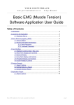
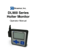
Mappings
Ch1
Ch2
Ch3
Ch4
Pre-defined Sequence 1
T3
T4
C3
C4
Pre-defined Sequence 2
F3
F4
P3
P4
Pre-defined Sequence 3
Fz
Pz
Cz
Oz
Pre-defined Sequence 4
F7
F8
T5
T6
Pre-defined Sequence 5
Fp1
Fp2
O1
O2
Default User Defined Ch1
Fp1/F3/F7
Default User Defined Ch2
Fp2/F4/F8
Default User Defined Ch3
T5/O1/P3
Default User Defined Ch4
T6/O2/P4
(these default locations are quadrants of the brain - this configuration can be re-programmed)
User Defined Mapping Choices
Choices:
Ch1
Ch2
Ch3
Ch4
Fp1
Fp2
F7
F8
F3
F4
T3
T4
C3
C4
T5
T6
P3
P4
O1
O2
F7
F8
C3
C4
T3
T4
P3
P4
Fpz
Cz
Cz
Fz
Fz
Pz
Pz
Oz
Note that sites should not be shared across slots as that will act to short the two eeg channels.
Controlling the Cap's User Defined Mapping from the PC Application
Some supporting Applications include the ability to control the mapping of the EEG Cap onto the 4 slots. If
the Q-Wiz is directly connected via USB then the Application can command mapping of the EEG Cap sites
on the fly - commands sent from the application will instantaneously configure the EEG Cap and the chosen
sites will be conveyed to the Application over the four slots.
If the Q-menu is not active at the time that the Q-Wiz receives a command to map the cap sites, the Q-Wiz
will automatically activate the multiplexer and save the new mapping as the User Defined mapping. Also, if
not already in Mode 4 (256sps/4ch), the Q-wiz will change to that mode.
If the Q-Wiz is connected via wireless, then select Mode 0 (Program Mode) to allow the PC Application to
command mapping of cap sites.
11. Poor Signal Detection
The Wiz monitors
• electrodes for Lead-off condition
• nIR HEG for signal strength
• pIR for values out of range
If any test fails, the "Good" LED is extinguished. This information, on a slot by slot basis, is also sent to the
PC Application. That is, each slot is separately reported as Good or not.
12. Test Signals
At power-up, a brief self-test sequence of test signals is sent to the transport slots and to the nIR HEG
headband. If the transport slot is configured for EEG use("AC"), then the test signal is a 4, 8, 16, and 32Hz
tone, each for one second. If the transport slot is configured for HEG use ("DC"), then the brief test signal is
values 99 and 101, each for 1 second.
Additionally, during this power-up self-test phase, control signals to the nIR HEG headband interface
separately pulse the Red and the IR LEDs, so that both can be seen with the naked eye. [In normal use, the
brightness of the Red LED makes it impossible to see whether the IR is functioning.]
If power is applied to the Wiz with the "Link"/"Calibrate" button pressed, then it will power-up in Signal
Generator Mode. In this mode the above test signals are applied indefinitely, until power to the unit is
removed, or both the "Link" button and the "Mode" button a pressed simultaneously to exit Signal Generator
Mode.
8 sec Self-Test on normal Power-up
EEG - 4/8/16/32Hz, at 1 second intervals
NIR - 99/101 at 1 sec intervals
13. Saving Configurations
When changing Modes, the new Mode is remembered. When the unit is next powered, it will come up in that
Mode. After a signal has settled, be it eeg or heg, pressing the Freeze button for 2sec will save the current
baseline so that the signal can settle more quickly when that modality is next selected. Functions that get
remembered:
• Mode: 32/128/512/256sps, 2ch/4ch
• Baseline offset values
• EEG Reference Link Status (linked or un-linked)
• wireless channel number
• User Defined Cap Mapping
14. Fail-safe Mode
Fail-safe Mode is entered by powering-up with the Mode button pressed. Fail-safe Mode offers base
functionality (ie is usable for most functions), and the ability to upload or re-load firmware upgrade packages
to restore full functionality. Fail-safe Mode comes up in Mode 2 (128sps/2ch), but other modes can then be
selected. Firmware upgrades are restored by placing the unit in Program Mode then using the PC Application
Software to upload the latest firmware package available from the pocket-neurobics.com website.
Functions that may not work in Fail-safe mode (model dependant):
• commanding of the Wiz by the PC Application
• pulse oximeter interface
Safety functions in Fail-safe Mode:
• extra time for USB enumeration (for slow PCs)
• freeze button locks current sensor configuration (to stop possible jitter on sensor detection in noisy
environments)