1
Specifications
Elektro GmbH & Co. KG
451 FU-BM DE
Movement detector - Ceiling Mounted
Installation and operating instructions
GB
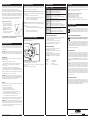
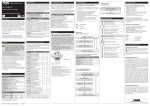
Structure and description
Lens
Button interface
37.5 mm
60 mm
160 mm
Planning
Power Supply
Standard: Solar cells from 50 lx
Optional: Battery to 50 lx (Cr2032 / 3 V DC)
Transmit frequency
868,3 MHz
EnOcean Equipment
Profile (EEP)
A5-07-01
Motion Sensing Range
12 m diameter
Time to Full Charge*
9 hours @ 200 lux
Charge Times*
Programming:4 - 6 minutes @ 100 lux
Light/Walk Test: 5,5 hours @ 200 lux
Sustaining Charge Time
3 hours per 24 hours @ 200 lux
Minimum Operating Light
50 lux
Operating Life
Solar Energy Storage
48 hours in total Darkness
(after full charge)
Operating Life
Battery
1 year in total Darkness
Interval
A status message is transmitted every two minutes.
Absence status message
The absence status message (no motion) is transmitted after ten and thirty minutes when no occupancy has been detected.
Life-Signal
After the last absence status message, the device
transmits hourly a life signal, confirming that it is
operating properly (deactivated by default).
Environment
(Indoor use only)
Temperature: -10° to 40°C
Humidity: 20% to 95% relative
(non-condensing)
Protection Type
IP50
Mounting Height
2,00 - 3,00 m (recommended)
Weight
125 g
Dimensions
160 mm x 60 mm x 37 mm
Agency Compliance
FCC, IC, RoHS, CE
Take a moment to plan for the sensor’s successful operation and optimal communication with other devices.
Remove the sensor from its packaging and place it under a bright light to provide the
required startup charge. Optionally, to ensure the sensor energy storage is fully charged, insert a CR2032 battery for 5 minutes while in a well-lit location.
• Ensure the location provides consistent and adequate light
• Locate the sensor between 7 - 10 ft (2.1 to 3 m) high
• Avoid installed near ceiling fan or hanging light fixtures.
• Consider the area’s traffic patterns and principal use, for example,
walking, working, lounging or sleeping
• Provide a minimum clearance of 4 ft. (1.2 m) away from heat sources,
light bulbs, forced air, or ventilation systems
• Consider the construction materials (such as metal) in the space and
obstacles that may interfere with RF signals
Immediately the movement detector detects motion, it transmits an occupancy (motion) status signal to the Easyclick receivers. A two minute interval is activated for the
transmission of status messages. No status message is transmitted inside this interval.
After the interval, the device again transmits the occupancy status message when
motion has been detected during this time. When no motion has been detected, the
device immediately transmits a signal on detecting new motion.
The absence status signal (no motion) is transmitted when no occupancy has been
detected over a longer period. The first message is transmitted after ten minutes, the
next after thirty minutes. A Life-signal can also be enabled.
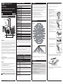
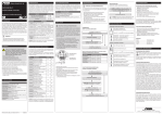
Motion Sensing Range
b) Mount using the Wire Bracket
–Remove the ceiling tile where you want to
mount the sensor.
–Place the mounting plate squarely on the
ceiling tile and mark two points for the holes.
–Punch two small holes through the ceiling tile
at the marked points.
–Insert the wire bracket through the two holes
in the mounting plate. Make sure the ends are
roughly even.
Top View
–Feed the wires through the holes in the
ceiling tile.
–On the front of the ceiling tile, flatten the
wire bracket so it is snug against the
mounting plate.
rF Range
A single movement detector provides sufficient coverage for most applications. For
some applications, multiple sensors may be required to provide complete coverage.
Radio signals are electromagnetic waves. The farther away the transmitter is, the weaker is the field strength surrounding the receiver. As such, the range is limited. Different
materials or interference sources in the direction of the signals can further reduce the
range. The range can be increased by the use of Easyclick Repeaters (radio amplifiers).
Material
Reduction
Wood, plaster, non-coated glass
0 - 10%
Masonry, wood/plaster walls
5 - 35%
Reinforced concrete
10 - 90%
Suitable Easyclick receivers:
All bidirectional Easyclick PRO dimming receivers and remote switches. A separate
light sensor can be installed for lighting control based on daylight exposure.
Range
Conditions
> 30 m
Under good conditions (large, clear space without obstructions).
Features
> 20 m
Through up to 5 plaster/drywall board walls or 2 plasterboard/
partition walls (furniture and people in the room):
For transmitter and receiver with good aerial positioning/layout.
> 10 m
Through up to 5 plaster/drywall board walls or 2 plasterboard/
partition walls (furniture and people in the room):
For receivers installed in walls or corners of rooms, receivers with
internal aerial or narrow corridors.
Through 1-2
ceilings / walls
Depending on ceiling/wall armouring and type of aerial in the
receiver.
• Sends wireless signals to receiving devices when motion is detected
• Harvests indoor light to power the sensor
• Mounts easily on any ceiling material.
• Works with other sensors
• Built-in tests to confirm operation at installed location
• Supplemental battery supply for extreme low-light conditions
Note: Go to www.peha.de for further information on “Range”.
Solar-operated energy storage
The energy storage must be charged before placing it into operation. The charging
time is approx. 4-6 min. at 100 LUX. The device is then ready for programming.
Caution! Before the movement detector can operate properly, the energy
storage must first have been charged for no longer than nine hours at 200 lx.
PEHA_M_451FU_BM_DE (Rev01_130724)
31060000-147
3. Decide which of the two installation options is appropriate.
–Hold the mounting plate in place on the
ceiling and use a pencil to lightly mark
two small dots for the screw drill points.
–Drill two holes and insert wall anchors.
–Insert the first screw loosely and level the
mounting plate.
–Insert the second screw and then
hand-tighten the first screw.
Application
The movement detector helps to save energy and detects motion precisely inside the
covered area. It is wireless, solar powered, and fitted with a passive infrared (IR) sensor.
The movement detector can be used for the efficient regulation of lighting, heating,
ventilation, and air conditioning systems and power consumers.
2. Remove the mounting plate from the sensor.
a)Screw Mounting Plate to the ceiling
* Sunlight, bright lighting or a battery can be temporarily used to significantly
shorten startup charge times. Specified lux values are for typical fluorescent
lighting. Other lux values may apply to other illuminants.
Solar Cells
1. Decide where you want to install the movement detector.
Tip: For visual alignment, orient the sensor parallel to one of the walls.
3m
Side View
–On the back of the ceiling tile, twist the wires
together to hold the mounting plate securely.
–Replace the ceiling tile.
0m
0m
0,9 1,4
2,3 2,8 3,3
3,9 4,25 5m
To provide coverage for very high ceilings, a wall sensor (e.g. 451 FU-BM) can be incorporated in the plan for complete coverage.
4. Attach the sensor to the mounting plate. With the button interface facing you,
slide the sensor to the left on the mounting plate until itsnaps into place.
Installing
Important installation information !
Installation and commissioning may only be performed by an authorised electrician.
Applicable laws and standards of the country in which the device is operated must
be observed! The movement detector can be mounted on most ceilings with the
provided screws, or mounted on dropped ceilings, using the provided wire bracket.
5. Confirm the sensor is properly positioned to detect motion and has sufficient light
to operate, see the Walk Test and Light Test sections.
• Only use indoors.
• It is often easier to programm the sensor before it is mounted on the ceiling.
• Place at least 2 m away from other radio transmitters.
• Consider the PLANNING when installing.
• Protect against moisture and spray water!
GB-1