1
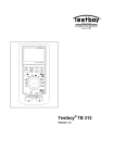
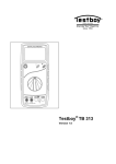
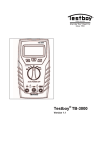
Testboy® TB 312
Version 1.0
®
3
®
29
Testboy TB 312
Bedienungsanleitung
Testboy TB 312
Operating Instructions
Inhaltsverzeichnis
Inhaltsverzeichnis
3
Hinweise
4
Allgemeine Sicherheitshinweise
4
Sicherheitshinweise
6
Bedienung
10
Einleitung
10
Schalter-, Taster- und Buchsenerklärung
12
Display
13
Gleichspannungsmessung / V=
15
Wechselspannungsmessung / V~
16
Gleichstrommessung / A=
17
Wechselstrommessung / A~
18
Kapazitätsmessung / F*
19
Widerstandsmessung / Ω
19
Diodentest
20
Durchgangstest
20
Frequenz
21
Tastverhältnis
21
Relativwert Messung
21
Wartung
22
Reinigung
22
Batteriewechsel
22
Sicherungswechsel
22
PC-Software
23
Technische Daten
Testboy® TB 312
27
3
DEUTSCH
Inhaltsverzeichnis
Hinweise
Hinweise
Allgemeine Sicherheitshinweise
WARNUNG
Aus Sicherheits- und Zulassungsgründen (CE) ist das eigenmächtige Umbauen und/oder Verändern des Gerätes nicht
gestattet. Um einen sicheren Betrieb mit dem Gerät zu gewährleisten, müssen Sie die Sicherheitshinweise, Warnvermerke
und das Kapitel "Bestimmungsgemäße Verwendung" unbedingt beachten.
WARNUNG
Beachten Sie vor dem Gebrauch des Gerätes bitte folgende
Hinweise:
4
|
Vermeiden Sie einen Betrieb des Gerätes in der Nähe von
elektrischen Schweißgeräten, Induktionsheizern und anderen elektromagnetischen Feldern.
|
Nach abrupten Temperaturwechseln muss das Gerät vor
dem Gebrauch zur Stabilisierung ca. 30 Minuten an die
neue Umgebungstemperatur angepasst werden um den
IR-Sensor zu stabilisieren.
|
Setzen Sie das Gerät nicht längere Zeit hohen Temperaturen aus.
|
Vermeiden Sie staubige und feuchte Umgebungsbedingungen.
|
Messgeräte und Zubehör sind kein Spielzeug und gehören
nicht in Kinderhände!
|
In gewerblichen Einrichtungen sind die Unfallverhütungsvorschriften des Verbandes der gewerblichen Berufsgenossenschaften für elektrische Anlagen und Betriebsmittel zu
beachten.
Testboy® TB 312
Hinweise
1
Freischalten
2
Gegen Wiedereinschalten sichern
3
Spannungsfreiheit feststellen (Spannungsfreiheit ist 2-polig festzustellen)
4
Erden und kurzschließen
5
Benachbarte unter Spannung stehende Teile abdecken
DEUTSCH
Bitte beachten Sie die fünf Sicherheitsregeln:
Bestimmungsgemäße Verwendung
Das Gerät ist nur für die in der Bedienungsanleitung beschriebenen Anwendungen bestimmt. Eine andere Verwendung ist unzulässig und kann zu Unfällen oder Zerstörung des Gerätes führen. Diese Anwendungen führen zu
einem sofortigen Erlöschen jeglicher Garantie- und Gewährleistungsansprüche des Bedieners gegenüber dem Hersteller.
Um das Gerät vor Beschädigung zu schützen, entfernen Sie bitte
bei längerem Nichtgebrauch des Gerätes die Batterien.
Bei Sach- oder Personenschäden, die durch unsachgemäße Handhabung oder Nichtbeachtung der Sicherheitshinweise verursacht
werden, übernehmen wir keine Haftung. In solchen Fällen erlischt
jeder Garantieanspruch. Ein in einem Dreieck befindliches Ausrufezeichen weist auf Sicherheitshinweise in der Bedienungsanleitung
hin. Lesen Sie vor Inbetriebnahme die Anleitung komplett durch.
Dieses Gerät ist CE-geprüft und erfüllt somit die erforderlichen
Richtlinien.
Rechte vorbehalten, die Spezifikationen ohne vorherige Ankündigung zu ändern
© Testboy GmbH, Deutschland.
Testboy® TB 312
5
Hinweise
Sicherheitshinweise
WARNUNG
Gefahrenquellen sind z.B. mechanische Teile, durch die es zu
schweren Verletzungen von Personen kommen kann.
Auch die Gefährdung von Gegenständen (z.B. die Beschädigung des Gerätes) besteht.
WARNUNG
Stromschlag kann zum Tod oder zu schweren Verletzungen
von Personen führen sowie eine Gefährdung für die Funktion
von Gegenständen (z.B. die Beschädigung des Gerätes) sein.
6
Testboy® TB 312
Hinweise
Haftungsausschluss
DEUTSCH
Bei Schäden, die durch Nichtbeachten der Anleitung verursacht
werden, erlischt der Garantieanspruch! Für Folgeschäden, die daraus resultieren, übernehmen wir keine Haftung!
Testboy haftet nicht für Schäden, die aus
|
dem Nichtbeachten der Anleitung
|
von Testboy nicht freigegebenen Änderungen am Produkt oder
|
von Testboy nicht hergestellten oder nicht freigegebenen Ersatzteilen
|
Alkohol-, Drogen- oder Medikamenteneinfluss hervorgerufen werden
resultieren.
Richtigkeit der Bedienungsanleitung
Diese Bedienungsanleitung wurde mit großer Sorgfalt erstellt. Für die Richtigkeit und Vollständigkeit der Daten, Abbildungen und Zeichnungen wird
keine Gewähr übernommen. Änderungen, Druckfehler und Irrtümer vorbehalten.
Entsorgung
Sehr geehrter Testboy-Kunde, mit dem Erwerb unseres Produktes haben
Sie die Möglichkeit, das Gerät nach Ende seines Lebenszyklus an geeignete
Sammelstellen für Elektroschrott zurückzugeben.
Die WEEE (2002/96/EC) regelt die Rücknahme und das Recycling von Elektroaltgeräten. Hersteller von Elektrogeräten sind ab
dem 13.8.2005 dazu verpflichtet, Elektrogeräte die nach diesem
Datum verkauft werden, kostenfrei zurückzunehmen und zu recyceln. Elektrogeräte dürfen dann nicht mehr in die „normalen“
Abfallströme eingebracht werden. Elektrogeräte sind separat zu
recyceln und zu entsorgen. Alle Geräte, die unter diese Richtlinie fallen, sind mit diesem Logo gekennzeichnet.
Testboy® TB 312
7
Hinweise
Entsorgung von gebrauchten Batterien
Sie als Endverbraucher sind gesetzlich (Batteriegesetz) zur
Rückgabe aller gebrauchten Batterien und Akkus verpflichtet;
eine Entsorgung über den Hausmüll ist untersagt!
Schadstoffhaltige Batterien/Akkus sind mit nebenstehenden
Symbolen gekennzeichnet, die auf das Verbot der Entsorgung
über den Hausmüll hinweisen.
Die Bezeichnungen für das ausschlaggebende Schwermetall
sind:
Cd = Cadmium, Hg = Quecksilber, Pb = Blei.
Ihre verbrauchten Batterien/Akkus können Sie unentgeltlich bei
den Sammelstellen Ihrer Gemeinde oder überall dort abgeben,
wo Batterien/Akkus verkauft werden!
5 Jahre Garantie
Testboy-Geräte unterliegen einer strengen Qualitätskontrolle. Sollten während der täglichen Praxis dennoch Fehler in der Funktion auftreten, gewähren wir eine Garantie von 5 Jahren (nur gültig mit Rechnung). Fabrikationsoder Materialfehler werden von uns kostenlos beseitigt sofern das Gerät ohne Fremdeinwirkung und ungeöffnet an uns zurückgesandt wird. Beschädigungen durch Sturz oder falsche Handhabung sind vom Garantieanspruch
ausgeschlossen.
Bitte wenden Sie sich an:
Testboy GmbH
Elektrotechnische Spezialfabrik
Beim Alten Flugplatz 3
D-49377 Vechta
Germany
8
Tel: 0049 (0)4441 / 89112-10
Fax: 0049 (0)4441 / 84536
www.testboy.de
[email protected]
Testboy® TB 312
Hinweise
Alle innerhalb der Testboy GmbH durchgeführten, qualitätsrelevanten Tätigkeiten und Prozesse werden permanent durch ein Qualitätsmanagementsystem überwacht. Die Testboy GmbH bestätigt weiterhin, dass die während
der Kalibrierung verwendeten Prüfeinrichtungen und Instrumente einer permanenten Prüfmittelüberwachung unterliegen.
Konformitätserklärung
Das Produkt erfüllt die Niederspannungsrichtlinien 2006/95/EG und die
EMV-Richtlinien 2004/108/EG.
Testboy® TB 312
9
DEUTSCH
Qualitätszertifikat
Bedienung
Bedienung
Einleitung
Das Testboy® TB 312 ist ein universell einsetzbares Multimeter. Das Messgerät wird nach den neuesten Sicherheitsvorschriften hergestellt und gewährleistet ein sicheres und zuverlässiges Arbeiten. Das Multimeter ist im
handwerklichen oder industriellen Bereich sowie für den Hobby-Elektroniker
eine wertvolle Hilfe bei allen Standard-Messaufgaben.
Lieferumfang
|
Multimeter TB 312
|
Sicherheitsmessleitungen (CAT III 1000 V)
|
Bedienungsanleitung
|
PC-Software (CD)
|
USB Kabel
Sicherheitsmaßnahmen
Das TB 312 hat das Werk in sicherheitstechnisch einwandfreiem Zustand
verlassen. Um diesen Zustand zu erhalten, muss der Anwender die Sicherheitshinweise in dieser Anleitung beachten.
Achtung!
Benutzen Sie nur die beigefügten Sicherheits-Messleitungen oder äquivalente Messleitungen, die der richtigen
Messkategorie CAT III 1000 V genügen.
10
Testboy® TB 312
| Um einen elektrischen Schlag zu vermeiden, sind die Vorsichtsmaßnahmen zu beachten, wenn mit Spannungen größer 70 V (35 V) DC oder
33 V (16 V) eff. AC gearbeitet wird. Diese Werte stellen nach DIN VDE
die Grenze der noch berührbaren Spannungen dar. (Werte in Klammern
gelten für z.B. medizinische oder landwirtschaftliche Bereiche)
| Vor jeder Messung vergewissern, dass die Messleitung und das Prüfgerät
in einwandfreiem Zustand sind.
| Die Messleitungen und Prüfspitzen dürfen nur an den dafür vorgesehenen Handgriffen angefasst werden. Das Berühren der Prüfspitzen ist unter allen Umständen zu vermeiden.
Das Prüfgerät darf nur in den spezifizierten Messbereichen eingesetzt werden.
Nach der Norm EN 61010-1 werden folgende Messkategorien definiert:
Messkategorie CAT II
Messungen an Stromkreisen die elektrisch direkt mit dem Netz verbunden
sind, über Stecker in Haushalt, Büro und Labor.
Messkategorie CAT III
Messungen an der Gebäudeinstallation: Stationäre Verbraucher, Verteileranschluss, Geräte fest am Verteiler.
Messkategorie CAT IV
Messungen an der Quelle der Niederspannungsinstallation: Zähler, primärer
Überspannungsschutz, Hauptanschluss.
Testboy® TB 312
11
DEUTSCH
Bedienung
Bedienung
Schalter-, Taster- und Buchsenerklärung
12
(1)
V/ Ω/dBm/Hz
Buchse
Rote Messleitung für alle
vom Gerät zulässigen Signalarten.
(2) COM
Buchse
Schwarze Messleitung für
alle vom Gerät zulässigen
Signalarten.
(3) mA Buchse
Für Strommessungen bis
500 mA
(4) 10 A Buchse
(links)
Bei Strommessungen ab
500 mA muss die 10 A
Buchse benutzt werden.
(5) Wahlschalter Messfunktion
Bei Betätigung des Drehschalters können die verschiedenen Grundmessarten gewählt werden.
(6) POWER
Schalter
Das Gerät wird über einen
„POWER“ Druckschalter
ein- und ausgeschaltet.
(7) RANGE
Taste
Manuelle Messbereichswahl
(8) SELECT
Taste (gelb)
Messartwahl (gelbe Beschriftung)
(9) WAKE Taste
Aufwecken des Gerätes
aus dem Schlafmodus
(10) MAX/MIN
Taste
Messwertanzeige MAX,
MIN und MAX-MIN Wert
(11) REL Taste
Umstellung auf Relativwertanzeige
(12) HOLD Taste
Messwertspeicherung
(13) LIGHT
Taste
Hintergrundbeleuchtung
(14) ~ HZ Taste
Frequenzmessung während Spannung- und
Strommessung
(15) LCD Anzeige
Siehe unten
Testboy® TB 312
Bedienung
DEUTSCH
Display
Nummer
Symbol
Funktion
1
Temperaturmessung °C oder °F
1
°C °F
mnF
mμA
dBmV
1
MKΩHz
1
1
Kapazitätsmessung nF oder mF
Strommessung µA, mA oder A
dBm oder Spannungsmessung mV oder V
Widerstandsmessung Ω, KΩ oder MΩ
Sowie Frequenzmessung Hz, KHz, MHz
Tastverhältnis in %
2
3
MAX-MIN
Messwerterfassung MAX maximaler, MIN minimaler, MAX-MIN differenzierter Wert
4
AUTO
Automatische Messbereichswahl
5
MANUAL
Manuelle Messbereichswahl
6
51000
Messwertanzeige 5, 50, 500 und 1000, 5000,
usw.
7
8
Testboy® TB 312
Batteriesymbol bei schwacher Batterie
Relativmessung
13
Bedienung
Durchgangsmessung
9
10
AC
Negative Messwert
11
12
DC
Please Wait ...
Warteanzeige beim Messen von Kapazitäten
von 50μF~5000μF im automatischen Messbereich, um die Geneuigkeit zu wahren, bis
der Kondensator komplett entladen wurde
Analoge Bargraph-Anzeige
15
16
Gleichspannung oder Gleichstrom
Messwertspeicherung
13
14
Wechselspannung oder Wechselstrommessung
PCLINK
USB Anbindung
Messwertanzeige
17
14
Testboy® TB 312
Bedienung
Mit dem Wahlschalter den geeigneten Bereich (mV oder V) einstellen. Die
schwarze Messleitung mit der „COM“-Buchse und die rote Messleitung mit
der roten V/mV/Ω Buchse verbinden. Messleitungen mit dem Prüfling verbinden. Messergebnis vom Display ablesen. Die Polarität der Spannung wird
ebenfalls angezeigt.
Gleichspannung
Messbereich
Auflösung
Genauigkeit
50 mV
0,001 mV
± 0,03 % v.M.+ 10 Digit
500 mV
0,01 mV
5V
0,1 mV
50 V
1 mV
500 V
10 mV
1000 V
0,1 V
± 0,03 % v.M.+ 6 Digit
-Eingangswiderstand: 10 MΩ.
-Max. Eingangsspannung: 1000 V DC.
Durch drücken der SELECT Taste kann zwischen DC, AC und AC+DC
Messverfahren umgestellt werden.
Testboy® TB 312
15
DEUTSCH
Gleichspannungsmessung / V=
Bedienung
Wechselspannungsmessung / V~
Mit dem Wahlschalter den geeigneten Bereich (mV oder V~) einstellen.
Durch Drücken der SELECT Taste auf AC stellen. Die schwarze Messleitung
mit der „COM“-Buchse und die rote Messleitung mit der roten V/mV/Ω Buchse verbinden. Messleitungen mit dem Prüfling verbinden. Messergebnis vom
Display ablesen.
Wechselspannung
Messbereich
Auflösung
50 mV
0,001 mV
500 mV
0,01 mV
5V
0,1 mV
50 V
1 mV
500 V
10 mV
1000 V
0,1 V
Genauigkeit
40 Hz – 1 kHz
± 0,5 % v.M.
+ 40 Digit
1 kHz – 10 kHz
10 kHz – 20 kHz
± 1 % v.M.
+ 40 Digit
± 2,5 %
v.M.
+ 40 Digit
n. spezifiziert
n. spezifiziert
n. spezifiziert
Angegebene Genauigkeit nur bei 10% bis 100% des Messbereiches gültig.
-Eingangswiderstand: 10 MΩ.
-Max. Eingangsspannung: 1000 V AC RMS, Frequenzbereich: 40 Hz- 20 kHz.
Durch drücken der SELECT Taste kann zwischen dem AC und dBm Messbereich umgestellt werden.
16
Testboy® TB 312
Bedienung
Mit dem Wahlschalter den geeigneten Bereich (µA, mA oder A) einstellen.
Die schwarze Messleitung mit der „COM“-Buchse und die rote Messleitung
mit der mA oder 10A Buchse verbinden. Messleitungen mit dem Prüfling
verbinden. Messergebnis vom Display ablesen. Die Stromrichtung wird
durch Vorzeichen ebenfalls angezeigt.
Bei einem Strom über 500 mA, muss zur Messung die „10 A“Buchse benutzt werden!
Gleichstrom
Messbereich
Auflösung
500 µA
0,01 µA
5000 µA
0,1 µA
5 mA
1 µA
50 mA
10 µA
500 mA
0,1 mA
10 A*
1 mA
Genauigkeit
± 0,15 % v.M. + 15 Digit
± 0,5 % v.M. + 10 Digit
- 500 mA-Bereich abgesichert durch eine F 500 mA / 1000 V.
- 10A-Bereich ist abgesichert durch F 10 A / 1000 V.
- im 10A-Bereich maximale Einschaltdauer beachten!
* Zum Schutz vor Überhitzung des Gerätes nach max.
10 Sekunden Messung eine Pause von 15 Minuten zwecks
Abkühlung einhalten.
Durch drücken der SELECT Taste kann zwischen DC, AC und AC+DC Messverfahren umgestellt werden.
Testboy® TB 312
17
DEUTSCH
Gleichstrommessung / A=
Bedienung
Wechselstrommessung / A~
Mit dem Wahlschalter den geeigneten Bereich einstellen. Die schwarze
Messleitung mit der „COM“-Buchse und die rote Messleitung mit der mA oder 10A Buchse verbinden. Messleitungen mit dem Prüfling verbinden. Messergebnis vom Display ablesen.
Bei einem Strom über 500 mA muss zur Messung die „10 A“Buchse benutzt werden!
Wechselstrom
Messbereich
Auflösung
500 µA
Genauigkeit
40 Hz – 1 kHz
1 kHz – 10 kHz
10 kHz – 20 kHz
0,01 µA
± 0,75 % v.M.
+ 20 Digit
± 1 % v.M.
+ 20 Digit
± 1,2 % v.M.
+ 5 Digit
5000 µA
0,1 µA
± 0,75 % v.M.
+ 10 Digit
± 1 % v.M.
+ 10 Digit
± 1,2 % v.M.
+ 5 Digit
50 mA
1 µA
± 0,75 % v.M.
+ 20 Digit
± 1 % v.M.
+ 20 Digit
± 1,2 % v.M.
+ 5 Digit
500 mA
10 µA
± 0,75 % v.M.
+ 10 Digit
± 1 % v.M.
+ 10 Digit
± 1,2 % v.M.
+ 5 Digit
5A
0,1 mA
± 0,75 % v.M.
+ 20 Digit
± 1,5 % v.M.
+ 20 Digit
± 1,2 % v.M.
+ 5 Digit
10 A*
1 mA
± 1 % v.M.
+ 10 Digit
± 1,5 % v.M.
+ 10 Digit
n. spezifiziert
Angegebene Genauigkeit nur bei 10% - 100% des Messbereiches gültig.
- 500 mA-Bereich ist abgesichert durch F 500 mA / 1000V.
- 10A-Bereich ist abgesichert durch F 10 A / 1000 V.
- im 10A-Bereich maximale Einschaltdauer beachten!
- Frequenzbereich: 40 - 20000 Hz.
* Zum Schutz vor Überhitzung des Gerätes nach max.
10 Sekunden Messung eine Pause von 15 Minuten zwecks
Abkühlung einhalten.
Durch drücken der SELECT Taste kann zwischen DC, AC und AC+DC
Messverfahren umgestellt werden.
18
Testboy® TB 312
Bedienung
Mit dem Wahlschalter den geeigneten Bereich einstellen. Die schwarze
Messleitung mit der „COM“-Buchse und die rote Messleitung mit der V/mV/Ω
Buchse verbinden. Messleitungen mit dem Prüfling verbinden. Messergebnis
vom Display ablesen.
Messbereich
Auflösung
50 nF
0,01 nF
500 nF
0,1 nF
5 µF
1 nF
50 µF
10 nF
500 µF
0,1 µF
5000 µF
1 µF
Genauigkeit
± 1 % + 5 Digit
± 2 % + 5 Digit
Eingangsimpedanz: 180 kΩ, Testspannung: 1,2 V, Teststrom. 2,5 mA
*Die Kondensatoren vor jeder Messung entladen!
Widerstandsmessung / Ω
Mit dem Wahlschalter den geeigneten Bereich einstellen. Die schwarze
Messleitung mit der „COM“-Buchse und die rote Messleitung mit der V/mV/Ω
Buchse verbinden. Messleitungen mit dem Prüfling verbinden. Messergebnis
vom Display ablesen.
Messbereich
Auflösung
Genauigkeit
500 Ω
0,01 Ω
± 0,1 % + 10 Digit
5 kΩ
0,1 Ω
50 kΩ
1Ω
500 kΩ
10 Ω
5 MΩ
100 Ω
± 0,1 % + 10 Digit
50 MΩ
1 kΩ
± 0,5 % + 10 Digit
± 0,1 % + 5 Digit
Eingangsimpedanz: 10 MΩ, Testspannung: 3 V, Teststrom: 2 mA.
Testboy® TB 312
19
DEUTSCH
Kapazitätsmessung / F*
Bedienung
Diodentest
Mit dem Wahlschalter auf „
“ einstellen. Die schwarze Messleitung mit
der „COM“-Buchse und die rote Messleitung mit der V/mV/Ω Buchse verbinden. Messleitungen mit dem Prüfling verbinden. Rote Messleitung = Anode,
Schwarze Messleitung = Kathode. Die Vorwärtsspannungsabfall wird angezeigt.
Messbereich
Auflösung
Anzeige
0,1 mV
Vorwärtsspannung
-Vorlaufstrom: ca. 0,7 mA, Rücklaufspannung: ca. 2,5 V.
Durchgangstest
Mit dem Wahlschalter auf „Ω / ◦)))“ einstellen. Mit der SELECT Taste auf
Durchgangsprüfung wechseln. Die schwarze Messleitung mit der „COM“Buchse und die rote Messleitung mit der V/mV/Ω Buchse verbinden. Messleitungen mit dem Prüfkreis verbinden. Bei einem Widerstand unter 60 Ω ertönt ein Signal.
Wichtig: Achten Sie auf Spannungsfreiheit und entladene Kondensatoren am Messkreis.
Messbereich
◦)))
20
Funktion
Der integrierte Summer meldet Durchgang bis 60 Ω
Testboy® TB 312
Bedienung
Den Wahlschalter auf „Hz“ einstellen. Die schwarze Messleitung mit der
„COM“-Buchse und die rote Messleitung mit der V/mV/Ω Buchse verbinden.
Messleitungen mit dem Prüfkreis verbinden. Messergebnis vom Display ablesen.
Messbereich
Auflösung
Genauigkeit
Logikfrequenz (2,5 ~ 5 Vp)
5 Hz ~ 2 MHz
0,001 Hz
± 0,006 % + 4 Digit
Linearfrequenz (500 mV ~ 1000 V, nur im AC Messbereich!)
5 Hz ~ 60 kHz
0,001 Hz
± 0,006 % + 4 Digit
- Eingangsimpedanz: 3 kΩ
Tastverhältnis
Den Wahlschalter auf „Hz“ einstellen. Durch drücken der Taste SELECT auf
den Tastverhältnis-Messbereich wechseln. Die schwarze Messleitung mit
der „COM“-Buchse und die rote Messleitung mit der V/mV/Ω Buchse verbinden. Messleitungen mit dem Prüfkreis verbinden. Messergebnis vom Display
ablesen.
Messbereich
Auflösung
Genauigkeit
Tastverhältnis (2,5 ~ 5 Vp bei 5 Hz ~ 60 kHz)
5 % ~ 95 %
0,01 %
± 2 % + 5 Digit
- Eingangsimpedanz: 3 kΩ
Relativwert Messung
Beim Drücken der Taste „REL“ schalten Sie das Relativwert Mssverfahren
ein. Beim Drücken der Taste wird der gerade gemessene oder angezeigte
Wert festgehalten und dem nachfolgendem abgezogen werden.
Die Taste „REL“ kann ebenfalls dazu genutzt werden den Widerstand der
messleitungen zu kompensieren.
Testboy® TB 312
21
DEUTSCH
Frequenz
Bedienung
Wartung
Das Gerät benötigt bei Betrieb gemäß der Bedienungsanleitung keine besondere Wartung.
Reinigung
Sollte das Gerät durch den täglichen Gebrauch schmutzig geworden sein, kann
das Gerät mit einem feuchten Tuch und etwas mildem Haushaltsreiniger gereinigt werden. Niemals scharfe Reiniger oder Lösungsmittel zur Reinigung verwenden.
Batteriewechsel
Der Batteriewechsel wird nötig, wenn das Batteriesymbol
im Display
erscheint. Vor dem Batteriewechsel müssen die Messleitungen vom Gerät
getrennt sein!
Rückseitig befindliche zwei Schrauben unter dem abklappbaren Standfuß
entfernen, Batteriefach öffnen und entladene Batterien entfernen. Neue Batterien (6 x 1,5 V AAA Micro) einlegen. Achten Sie auf richtige Polarität. Batteriefach aufsetzen und zuschrauben.
Verwenden Sie nur die angegebenen Batterien!
Batterien gehören nicht in den Hausmüll! Beachten Sie die gesetzlichen Entsorgungsvorschriften!
Sicherungswechsel
Bei nötigen Sicherungswechsel vorher Messleitungen vom Gerät entfernen
und rückseitige zwei Schrauben des Batteriefaches hinter dem abklappbaren Standfuß lösen. Den batteriefachdeckel vorsichtig entfernen und die entsprechende Schutzkappe der zu wechselnden Sicherung abheben und die
defekte Sicherung mit einer des gleichen Typs (Sicherung F 10 A / 1000 V
oder F 500 mA / 1000V) ersetzen. Schutzkappe wieder aufsetzen und Batteriefach wieder zuschrauben
Verwenden Sie nur Sicherungen mit den angegebenen Werten!
22
Testboy® TB 312
Bedienung
PC-Software
Öffnen Sie den Inhalt der CD im Explorer Ihres PC auf und führen Sie die
Setup.exe aus.
DEUTSCH
Es erscheint folgendes Auswahlmenü:
Klicken Sie auf die entsprechende Schaltfläche für die Sprache.
Nun erscheint nach entpacken der Installationsdateien der Installationsassistent:
Testboy® TB 312
23
Bedienung
Klicken Sie auf „Next“, wählen Sie den Installationsorder und
klicken wieder auf „Next“ und dann auf „Install“, am Ende der
Installation auf „Finish“:
Unter Programme/Multimeter klicken Sie auf Multimeter.exe
oder doppelklicken Sie auf das Multimeter.exe-Icon auf dem
Desktop und es erscheint das Hauptfenster:
24
Testboy® TB 312
Bedienung
DEUTSCH
Schließen Sie das Multimeter an eine USB-Schnittstelle Ihres
PCs an und halten die Taste „HOLD“ gedrückt, bis „PCLINK“ im
Display erscheint.
Wenn der Treiber nicht automatisch installiert wird, öffnen Sie
auf der CD den Ordner „drivers“
Und führen den xxxInstaller.exe im jeweiligen Ordner Ihres
Betriebssystemes aus.
Folgende Betriebssysteme werden unterstützt: Windows 2000,
XP, 2003, Vista und Windows 7.
Nach erfolgter Installation der Treiber wird ine virtuelle COMSchnitstelle generiert, schauen Sie bitte in den Gerätemanager
nach dem zugewiesenen COM-Port (COM2, COM3…).
Stellen Sie diesen COM-Port im Hauptfenster des Programmes
links oben ein und drücken auf „Verbindung“.
Je nach Stellung des Drehschalters am Multimeter sehen Sie
eine Kopie der Anzeige im linken oberen Bereich des
Hauptfensters, darunter ein XY-Diagramm, auf der rechten
Seite werden die Date in eine Liste übertragen, die Sie dann
einfach speichern, in EXCEL übertragen oder drucken können.
Testboy® TB 312
25
Bedienung
Mit Hilfe weiterer Werkzeuge könne Sie die Ansicht des XYDiagrammes verändern:
Durch Bedienung der oberen Pfeile können Sie die Zeitbasis
verändern (X), durch Bedienung der seitlichen Pfeile die YAchse. Durch klicken auf „Druck“ wird der Inhalt der aktuellen
Anzeige dem Drucker übergeben.
26
Testboy® TB 312
Technische Daten
Beenden Sie das Programm indem Sie das Hauptfenster
schließen.
DEUTSCH
Technische Daten
Die Genauigkeit bezieht sich auf 1 Jahr bei einer Temperatur von 18 °C 28 °C mit einer Luftfeuchtigkeit von 75 % (weitere jährliche Kalibrierungen
werden angeboten).
Max. Spannung zwischen den Anschlussbuchsen und Masse:
1000 V AC / DC.
Sicherungen
F 500 mA 1000 V flink
F10 A 1000 V flink
Max. Betriebshöhe
2000 m über NN
Displayhöhe
40 mm LCD mit Bargraphanzeige
Anzeige
max 59999 (4¾ Digit)
Polaritätsanzeige
automatisch
Überlaufanzeige
„1 “ wird angezeigt
Abtastrate
ca. 330 ms.
Batteriezustand
Batteriesymbol wird angezeigt
Stromversorgung
6 x 1,5 V AAA Micro
Betriebstemperatur
0 °C bis 50 °C RH <80%
Lagertemperatur
-20 °C bis 60 °C RH <80%
Abmessungen
210 x 105 x 45 mm
Gewicht
560 g inkl. Batterie
Kategorie
CAT III 1000 V
Schnittstelle
USB, optische Ankopplung
Testboy® TB 312
27
Technische Daten
28
Testboy® TB 312
Table of Contents
Table of Contents
Table of Contents
29
Notes
30
General safety notes
30
Safety notes
32
36
Introduction
36
Switches, buttons and jacks description
38
Display
39
DC voltage measurement / V=
41
AC voltage measurement / V~
42
DC current measurement / A=
43
AC current measurement / A~
44
Capacitance measurement / F*
45
Resistance measurement / Ω
45
Diode test
46
Continuity test
46
Frequency
47
Duty cycle
47
Relative value measurement
47
Maintenance
48
Cleaning
48
Changing the batteries
48
Changing the fuse
48
PC software
49
Technical data
Testboy® TB 312
53
29
ENGLISH
Operation
Notes
Notes
General safety notes
WARNING
Unauthorised modification and/or changes to the instrument
are not permitted, for reasons of safety and approval (CE). In
order to ensure safe and reliable operation using the instrument, you must always observe the safety instructions, warnings and the information contained in the section "Intended
use".
WARNING
Please observe the following information before using the instrument:
30
|
Do not operate the instrument anywhere near electrical
welders, induction heaters or other electromagnetic fields.
|
Further to abrupt temperature fluctuation, the instrument
must be allowed to adjust to the new ambient temperature
for approx. 30 minutes before using it, in order to stabilise
the IR sensor.
|
Do not expose the instrument to high temperatures for a
long period of time.
|
Avoid dusty and humid environments.
|
Measuring instruments and their accessories are not toys,
and must be kept out of the reach of children!
|
In industrial facilities, the accident prevention regulations for
electrical systems and equipment, established by the employer's liability insurance association, must be observed.
Testboy® TB 312
Notes
Please observe the five safety rules:
1
Disconnect
2
Ensure that the instrument cannot be switched back on again
3
Ensure isolation from the power supply (check that there is no
voltage on both poles)
4
Earth and short-circuit
5
Cover adjacent live parts
The instrument is intended strictly for use in applications described in the
operating instructions. Any other usage is considered improper and forbidden, and can result in accidents or the destruction of the instrument. Any
such application will result in the immediate expiry of all guarantee and warranty claims on the part of the operator against the manufacturer.
Remove the batteries if the instrument is not in use for a long period
of time, in order to protect the instrument from damage.
We assume no liability for damages to property or personal injury
caused by improper handling or failure to observe the safety instructions. Any warranty claim expires in such cases. An exclamation
mark in a triangle indicates safety notices in the operating instructions. Read the instructions completely before beginning the initial
commissioning. This instrument is CE-approved and thus fulfils the
required guidelines.
All rights reserved to alter specifications without prior notice
© Testboy GmbH, Germany.
Testboy® TB 312
31
ENGLISH
Intended use
Notes
Safety notes
WARNING
Sources of danger are mechanical parts, for example, which
can cause serious personal injury.
Objects are also at risk (e.g. damage to the instrument).
WARNING
An electric shock can result in death or serious personal injury,
and also functional damage to objects (e.g. damage to the instrument).
32
Testboy® TB 312
Notes
Disclaimer
The warranty claim expires in cases of damages caused by failure
to observe the instructions! We assume no liability for any resulting
damage!
|
failure to observe the instructions
|
changes to the product that have not been approved by Testboy or
|
the use of replacement parts that have not been approved or manufactured by Testboy
|
the use of alcohol, drugs or
ENGLISH
Testboy is not responsible for damage resulting from
medication.
Accuracy of the operating instructions
These operating instructions have been compiled with due care and attention. No guarantee is given that the data, illustrations and drawings are complete or correct. All rights reserved with regard to changes, printing mistakes
and errors.
Disposal
Dear Testboy customer: purchasing our product gives you the option of returning the instrument to suitable collection points for waste electrical
equipment at the end of its lifespan.
The WEEE Directive (2002/96/EC) regulates the return and recycling of waste electrical and electronics equipment. As of
13.08.2005, manufacturers of electrical and electronics equipment are obliged to take back and recycle any electrical devices
sold after this date free of charge After that date, electrical devices must no longer be disposed of through the "normal" waste
disposal channels. Electrical devices must be recycled and disposed of separately. All devices that fall under this directive
must feature this logo.
Testboy® TB 312
33
Notes
Disposal of used batteries
As an end user, you are legally obliged (battery law) to return
all used batteries; disposal with normal domestic waste is
prohibited!
Batteries containing contaminant material are labelled with adjacent symbols indicating the prohibition of disposal with normal
domestic waste.
The abbreviations used for the respective heavy metals are:
Cd = cadmium, Hg = mercury, Pb = lead.
You can return your used batteries free of charge to collection
points in your community or anywhere where batteries are sold!
5-year warranty
Testboy instruments are subject to strict quality control standards. If, during
the course of normal daily use, a fault should occur, we provide a 5-year
warranty (valid only with invoice). We will repair production or material defects free of charge upon return, provided the instrument has not been tampered with and is returned to us unopened. Damages resulting from dropping or improper handling are not covered by the warranty.
Please contact:
Testboy GmbH
Electrical Engineering Works
Beim Alten Flugplatz 3
D-49377 Vechta
Germany
34
Tel: 0049 (0)4441 / 89112-10
Fax: 0049 (0)4441 / 84536
www.testboy.de
[email protected]
Testboy® TB 312
Notes
Certificate of quality
All activities and processes carried out within Testboy GmbH relating to quality are monitored permanently within the framework of a Quality Management System. Furthermore, Testboy GmbH confirms that the testing equipment and instruments used during the calibration process are subject to a
permanent inspection process.
Declaration of conformity
ENGLISH
This product fulfils the specifications contained in the Low Voltage Directive
2006/95/EC and the EMC Directive 2004/108/EC.
Testboy® TB 312
35
Operation
Operation
Introduction
The Testboy® TB 312 is a universal multimeter. This measuring instrument
has been manufactured to the latest safety specifications, and guarantees
safe and reliable operation. The multimeter is a valuable aid for all standard
measurement tasks in trade and industry as well as for electronics hobbyists.
Scope of delivery
|
Multimeter TB 312
|
Safety test leads (CAT III 1000 V)
|
Operating instructions
|
PC software (CD)
|
USB cable
Safety precautions
The TB 312 left the factory with its safety features in perfect working order.
In order to maintain this condition, the user must observe the safety notes
contained in this manual.
Caution!
Use only the enclosed safety test leads or equivalent test
leads that meet the correct measurement category CAT III
1000 V.
36
Testboy® TB 312
Operation
| In order to avoid risk of electric shock, you must observe the specified
precautions when working with voltages greater than 70 V (35 V) DC or
33 V (16 V) eff AC. These values represent the limits of safe-to-touch voltages in accordance with DIN VDE. (Values given in brackets apply to
medical or agricultural areas, for example)
| Before taking each measurement, ensure that the test lead and the test
instrument are in perfect working order
The test instrument must only be used for the measuring ranges
specified.
According to the standard EN 61010-1, the following measurement categories are defined:
Measurement category CAT II
Measurements on circuits that are directly electrically connected to the network, via plugs in the home, office and laboratory.
Measurement category CAT III
Measurements on building installations: fixed consumer units, distributor
connection, equipment fitted permanently to the distributor
Measurement category CAT IV
Measurements at the source of the low voltage installation: meters, primary
surge protection, mains connection.
Testboy® TB 312
37
ENGLISH
| The test leads and test probes must only be handled using the grips provided. Avoid touching the test probes under any circumstances.
Operation
Switches, buttons and jacks description
38
(1)
V/ Ω/dBm/Hz
jack
Red test lead for all types
of signals supported by the
instrument.
(2) COM
jack
Black test lead for all types
of signals supported by the
instrument.
(3) mA jack
For current measurements
up to 500 mA
(4) 10 A jack
(left)
The 10 A jack must be
used for current measurements above 500 mA.
(5) Measuring
function selector switch
Use the rotary selector
switch to select the various
basic measurement modes.
(6) POWER
switch
The device is turned on
and off via a "POWER"
push-button switch.
(7) RANGE
button
Manual measuring range
selection
(8) SELECT
button (yellow)
Measurement type selection (yellow lettering)
(9) WAKE button
Wakes the instrument from
sleep mode
(10) MAX/MIN
button
Measured value display
MAX, MIN and MAX-MIN
value
(11) REL button
Switch-over to relative value display
(12) HOLD button
Measured value storage
(13) LIGHT button
Backlighting
(14) ~ HZ button
Frequency measurement
during voltage and current
measurement
(15) LCD display
See below
Testboy® TB 312
Operation
ENGLISH
Display
Number
Icon
Function
1
Temperature measurement °C or °F
1
°C °F
mnF
mμA
dBmV
1
MKΩHz
1
1
Capacitance measurement nF or mF
Current measurement µA, mA or A
dBm or voltage measurement mV or V
Resistance measurement Ω, KΩ or MΩ
Also frequency measurement Hz, KHz, MHz
Duty cycle in %
2
3
MAX-MIN
Measured value recording MAX maximum,
MIN minimum, MAX-MIN differentiated value
4
AUTO
Automatic measuring range selection
5
MANUAL
Manual measuring range selection
6
51000
Measured value display 5, 50, 500 and 1000,
5000, etc.
7
8
Testboy® TB 312
Battery icon indicating low battery
Relative measurement
39
Operation
Continuity measurement
9
10
AC
Negative measured value
11
12
DC
Please Wait …
Pause indicator when measuring capacitances of 50μF 5000μF in the automatic measuring range, in order to maintain accuracy until
the capacitor has been completely discharged
Analogue bargraph display
15
16
Direct voltage or direct current
Measured value storage
13
14
Alternating voltage or alternating current measurement
PCLINK
USB connection
Measured value display
17
40
Testboy® TB 312
Operation
DC voltage measurement / V=
Set the appropriate range (mV or V) using the selector switch. Connect the
black test lead to the “COM” jack and the red test lead to the red V/mV/Ω
jack. Connect test leads to the test specimen. Read off measurement result
from the display. The voltage polarity is also displayed.
Measuring range
Resolution
Accuracy
50 mV
0.001 mV
± 0.03 % of meas. val. + 10 digits
500 mV
0.01 mV
5V
0.1 mV
50 V
1 mV
500 V
10 mV
1000 V
0.1 V
ENGLISH
DC voltage
± 0.03 % of meas. val.+ 6 digits
-Input resistance: 10 MΩ.
-Max. input voltage: 1000 V DC.
Press the SELECT button to switch between DC, AC and AC+DC measurement methods.
Testboy® TB 312
41
Operation
AC voltage measurement / V~
Set the appropriate range (mV or V~) using the selector switch. Press the
SELECT button to set to AC. Connect the black test lead to the “COM” jack
and the red test lead to the red V/mV/Ω jack. Connect test leads to the test
specimen. Read off measurement result from the display.
AC voltage
Measuring
range
Resolution
50 mV
0.001 mV
500 mV
0.01 mV
5V
0.1 mV
50 V
1 mV
500 V
10 mV
1000 V
0.1 V
Accuracy
40 Hz – 1 kHz
± 0.5 % of
meas. val.
+ 40 digits
1 kHz – 10 kHz
± 1 % of
meas. val.
+ 40 digits
10 kHz – 20 kHz
± 2.5 % of
meas. val.
+ 40 digits
not specified
not specified
not specified
Accuracy specified only valid for 10% to 100% of the measuring range.
-Input resistance: 10 MΩ.
-Max. input voltage: 1000 V AC RMS, frequency range: 40 Hz- 20 kHz.
Press the SELECT button to switch between the AC and dBm measuring
range.
42
Testboy® TB 312
Operation
DC current measurement / A=
Set the appropriate range (µA, mA or A) using the selector switch. Connect
the black test lead to the “COM” jack and the red test lead to the mA or 10A
jack. Connect test leads to the test specimen. Read off measurement result
from the display. The current direction is indicated by the sign.
You must use the “10 A” jack when measuring currents above
500 mA!
Measuring range
Resolution
500 µA
0.01 µA
5000 µA
0.1 µA
5 mA
1 µA
50 mA
10 µA
500 mA
0.1 mA
10 A*
1 mA
ENGLISH
Direct current
Accuracy
± 0.15 % of meas. val.
+ 15 digits
± 0.5 % of meas. val.
+ 10 digits
- 500 mA range is protected by a F 500 mA / 1000 V fuse.
- 10A range is protected by a F 10 A / 1000 V fuse.
- in the 10A range observe the maximum duty cycles!
* Following measurement, which should take a max.
10 seconds, allow the instrument to cool down for 15 minutes
to protect against overheating.
Press the SELECT button to switch between DC, AC and AC+DC measurement methods.
Testboy® TB 312
43
Operation
AC current measurement / A~
Set the appropriate range using the selector switch. Connect the black test
lead to the “COM” jack and the red test lead to the mA or 10A jack. Connect
test leads to the test specimen. Read off measurement result from the display.
You must use the “10 A” jack when measuring currents above
500 mA!
Alternating current
Measuring
range
Resolution
500 µA
0.01 µA
5000 µA
0.1 µA
50 mA
1 µA
500 mA
10 µA
5A
0.1 mA
10 A*
1 mA
Accuracy
40 Hz – 1 kHz
1 kHz – 10 kHz
10 kHz – 20 kHz
± 0.75 % of
meas. val.
+ 20 digits
± 0.75 % of
meas. val.
+ 10 digits
± 0.75 % of
meas. val.
+ 20 digits
± 0.75 % of
meas. val.
+ 10 digits
± 0.75 % of
meas. val.
+ 20 digits
± 1 % of
meas. val.
+ 10 digits
± 1 % of
meas. val.
+ 20 digits
± 1 % of
meas. val.
+ 10 digits
± 1 % of
meas. val.
+ 20 digits
± 1 % of
meas. val.
+ 10 digits
± 1.5 % of
meas. val.
+ 20 digits
± 1.5 % of
meas. val.
+ 10 digits
± 1.2 % of
meas. val.
+ 5 digits
± 1.2 % of
meas. val.
+ 5 digits
± 1.2 % of
meas. val.
+ 5 digits
± 1.2 % of
meas. val.
+ 5 digits
± 1.2 % of
meas. val.
+ 5 digits
not specified
Accuracy specified only valid for 10% - 100% of the measuring range.
- 500 mA range is protected by a F 500 mA / 1000V fuse.
- 10A range is protected by a F 10 A / 1000 V fuse.
- in the 10A range observe the maximum duty cycles!
- Frequency range: 40 - 20000 Hz.
* Following measurement, which should take a max. 10 seconds, allow the instrument to cool down for 15 minutes to protect against overheating.
Press the SELECT button to switch between DC, AC and AC+DC measurement methods.
44
Testboy® TB 312
Operation
Capacitance measurement / F*
Set the appropriate range using the selector switch. Connect the black test
lead to the “COM” jack and the red test lead to the V/mV/Ω jack. Connect test
leads to the test specimen. Read off measurement result from the display.
Resolution
50 nF
0.01 nF
500 nF
0.1 nF
5 µF
1 nF
50 µF
10 nF
500 µF
0.1 µF
5000 µF
1 µF
Accuracy
± 1 % + 5 digits
ENGLISH
Measuring range
± 2 % + 5 digits
Input impedance: 180 kΩ, test voltage: 1,2 V, test current: 2.5 mA
*Discharge the capacitors before every measurement!
Resistance measurement / Ω
Set the appropriate range using the selector switch. Connect the black test
lead to the “COM” jack and the red test lead to the V/mV/Ω jack. Connect test
leads to the test specimen. Read off measurement result from the display.
Measuring range
Resolution
Accuracy
500 Ω
0.01 Ω
± 0.1 % + 10 digits
5 kΩ
0.1 Ω
50 kΩ
1Ω
500 kΩ
10 Ω
5 MΩ
100 Ω
± 0.1 % + 10 digits
50 MΩ
1 kΩ
± 0.5 % + 10 digits
± 0.1 % + 5 digits
Input impedance: 10 MΩ, test voltage: 3 V, test current: 2 mA.
Testboy® TB 312
45
Operation
Diode test
Set to “
” using the selector switch. Connect the black test lead to the
“COM” jack and the red test lead to the V/mV/Ω jack. Connect test leads to
the test specimen. Red test lead = anode, black test lead = cathode. The
forward voltage drop is displayed.
Measuring range
Resolution
Display
0.1 mV
Forward voltage
-Forward current: approx. 0.7 mA, flyback voltage: approx. 2.5 V.
Continuity test
Set to “Ω / ◦)))” using the selector switch. Switch to continuity testing using
the SELECT button. Connect the black test lead to the “COM” jack and the
red test lead to the V/mV/Ω jack. Connect test leads to the test circuit. A signal is emitted if a resistance under 60 Ω is measured.
Important: Ensure isolation from the power supply and discharge
capacitors in the circuit to be measured.
Measuring range
◦)))
46
Function
The integrated buzzer signals continuity of
up to 60 Ω
Testboy® TB 312
Operation
Frequency
Set the selector switch to “Hz”. Connect the black test lead to the “COM” jack
and the red test lead to the V/mV/Ω jack. Connect test leads to the test circuit. Read off measurement result from the display.
Measuring range
Resolution
Accuracy
Logic frequency (2.5 ~ 5 Vp)
5 Hz ~ 2 MHz
0.001 Hz
± 0.006 % + 4 digits
Linear frequency (500 mV ~ 1000 V, only in the AC measuring range!)
0.001 Hz
± 0.006 % + 4 digits
ENGLISH
5 Hz ~ 60 kHz
- Input impedance: 3 kΩ
Duty cycle
Set the selector switch to “Hz”. Press the SELECT button to switch to the duty cycle measurement range. Connect the black test lead to the “COM” jack
and the red test lead to the V/mV/Ω jack. Connect test leads to the test circuit. Read off measurement result from the display.
Measuring range
Resolution
Accuracy
Duty cycle (2.5 ~ 5 Vp at 5 Hz ~ 60 kHz)
5 % ~ 95 %
0.01 %
± 2 % + 5 digits
- Input impedance: 3 kΩ
Relative value measurement
Press the “REL” button to enable the relative value measurement method.
Pressing the button retains the last measured or displayed value and deducts the subsequent value.
The “REL” button can also be used to compensate for test lead resistance.
Testboy® TB 312
47
Operation
Maintenance
The instrument does not require special maintenance when used as specified in
these operating instructions.
Cleaning
Use a damp cloth and mild household detergent to clean the instrument should
it become soiled through daily use. Never use aggressive cleaning agents or
solvents to clean the instrument.
Changing the batteries
Change the batteries when the battery icon
is displayed. Remove
the test leads from the instrument before changing the batteries!
Remove the two screws on the rear of the instrument below the fold-down
pedestal, open the battery compartment and remove the spent batteries. Insert new batteries (6 x 1.5 V AAA Micro). Ensure that the polarity is correct.
Replace battery compartment and screw tight.
Only use the batteries specified!
Batteries must not be disposed of with normal domestic waste!
Observe the statutory regulations pertaining to disposal!
Changing the fuse
When you need to change the fuse, first remove the test leads from the instrument and remove the battery compartment's two screws on the rear behind the fold-down pedestal. Carefully remove the battery compartment lid,
lift off the relevant protective cap of the fuse that is to be changed and replace the defective fuse with one of the same sort (F 10 A / 1000 V or
F 500 mA / 1000V fuse). Replace the protective cap and retighten the
screws of the battery compartment.
Only use fuses with the values specified!
48
Testboy® TB 312
Operation
PC software
Open up the contents of the CD in your PC's Explorer and run the Setup.exe.
ENGLISH
The following drop-down menu appears:
Click on the relevant button for the language.
After unpacking the installation files, the InstallShield Wizard
appears:
Testboy® TB 312
49
Operation
Click on “Next”, select the installation directory and click again
on “Next” and then on “Install”, and once installation is complete
click on “Finish”:
Under Programme/Multimeter click on Multimeter.exe or double
click on the Multimeter.exe icon on the desktop and the main
window appears:
50
Testboy® TB 312
Operation
Connect the multimeter to a USB port on your PC and hold
down the “HOLD” button until “PCLINK” appears on the display.
If the driver is not installed automatically, open the “drivers”
folder on the CD
Run the xxxInstaller.exe in the appropriate folder of your
operating system.
Once the drivers have been installed successfully, a virtual
COM port is generated. Please refer to the device manager for
the assigned COM port (COM2, COM3, etc).
Configure this COM port in the program's main window (top left)
and press “Connection”.
Depending on where the rotary selector switch is positioned on
the multimeter, you will see a copy of the display in the top left
section of the main window, with an XY plot beneath it, and on
the right-hand side the data is transferred to a list that you can
then easily save, transfer to EXCEL or print.
Testboy® TB 312
51
ENGLISH
The following operating systems are supported: Windows 2000,
XP, 2003, Vista and Windows 7.
Operation
You can change the view of the XY plot using other tools:
You can change the time base (X-axis) by using the top arrows,
and the Y-axis by using the side arrows. Clicking on “Print”
sends the contents of the current display to the printer.
Exit the programme by closing the main window.
52
Testboy® TB 312
Technical data
Technical data
The accuracy relates to 1 year used at temperatures of 18 °C - 28 °C and
75 % humidity (further annual calibrations are offered).
Max. voltage between the connection socket and ground:
1000 V AC / DC.
Fuses
F 500 mA 1000 V quick-acting
Max. operating height
2000 m above MSL
Height of display
40 mm LCD with bargraph display
Display
max 59999 (4¾ digits)
Polarity indicator
Automatic
Over-range indicator
“1” is displayed
Sampling rate
Approx. 330 ms.
Battery status
Battery icon is displayed
Power supply
6 x 1.5 V AAA Micro
Operating temperature
0 °C to 50 °C RH <80%
Storage temperature
-20 °C to 60 °C RH <80%
Dimensions
210 x 105 x 45 mm
Weight
560 g incl. battery
Category
CAT III 1000 V
Interface
USB, optical coupling
Testboy® TB 312
ENGLISH
F10 A 1000 V quick-acting
53
Technical data
54
Testboy® TB 312
Technical data
Testboy® TB 312
55
Testboy GmbH
Elektrotechnische Spezialfabrik
Beim Alten Flugplatz 3
D-49377 Vechta
Germany
Tel: 0049 (0)4441 / 89112-10
Fax: 0049 (0)4441 / 84536
www.testboy.de
[email protected]