1
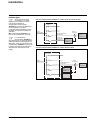
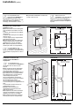
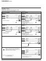
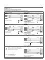
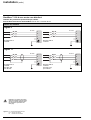
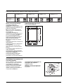
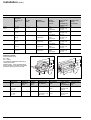
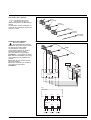
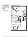
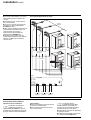
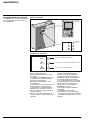
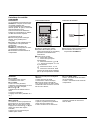
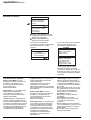
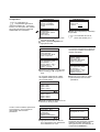
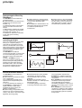
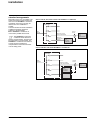
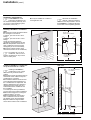
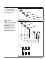
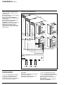
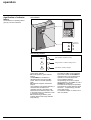
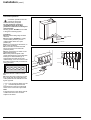
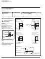
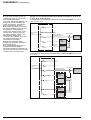
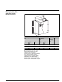
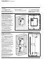
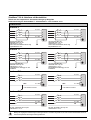
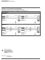
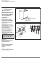
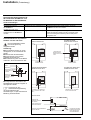
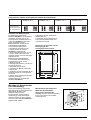
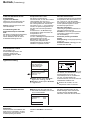
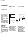
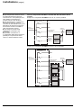
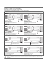
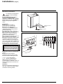
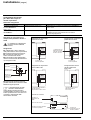
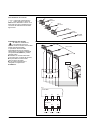
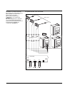
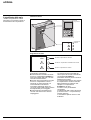
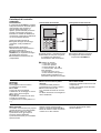
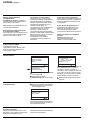
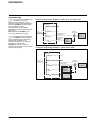
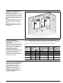
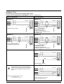
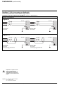
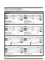
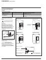
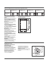
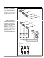
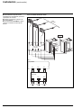
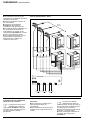
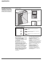
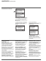
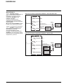
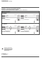
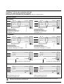
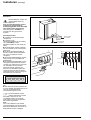
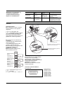
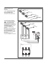
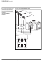
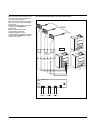
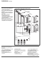
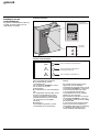
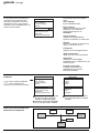
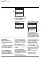
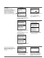
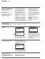
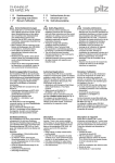
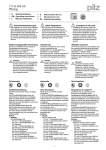
installation (cont.)
n an intermediary terminal block (not
supplied) must be installed for the 3
current sensors:
n it enables each of the 3 secondaries
to be short-circuited;
n one of the control SineWave™
conditioners shall be connected to this
terminal block;
n the connection leads supplied with
the conditioners will allow the
SineWave™ conditioners to operate in
parallel via a loop communication;
n other leads supplied with the
conditioners will ensure connections
between the two cubicles which make
up each 120 A.
For 90 A or 120 A parallel units:
phase 1
phase 2
to
load
phase 3
Y
DUMd
boar
Y
DUMd
boar
ard
Y bo
MER
rd
Y boa
MER
1 terminal block
not supplied
board
PARY
see fig. 1
board
PARY
Fig. 1
PARY board
XR1
S1
XR2
S2
phase 1
S1
XR3
S2
phase 2
S1
S2
phase 3
Connecting sensors
Connection operations
☞
The signal cables connecting
the current sensors to the
SineWave™ conditioner must be
moved away from the power cables so
that any disturbance is avoided.
26
Procedure:
n wiring is connected via the bottom, in
front of the conditioner;
n the signal cables connections are
made on 3 screw terminals.
☞
The signal cables must be
mechanically fixed near the
terminals so that any mechanical stress
on the conductors is avoided:
n put back the protection panels and
close the door;
n close the SineWave™ conditioner
protection circuit-breaker.
installation and operation manual of SineWave™: E-51027008XT/AD
MGE UPS SYSTEMS