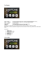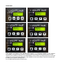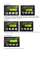
1
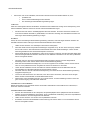
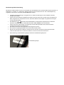
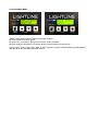
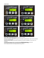
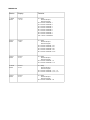
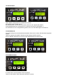
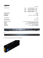
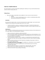
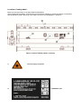
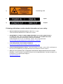
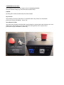
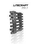
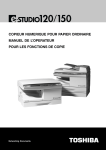
Vielen Dank für den Kauf dieses Lightline Produktes. Zu Ihrer eigenen Sicherheit lesen Sie bitte vor der ersten Inbetriebnahme diese Bedienungsanleitung sorgfältig. lightline Lightline Lasertechnik GmbH Lengericher Landstrasse 44 D-49078 Osnabrück www.lightline.de Tel. +49 (0) 541 685393-0 Sicherheitshinweise Jede Person, die mit der Installation, dem Einsatz oder dem Service des Gerätes betraut ist, muss: qualifiziert sein einen Laserschutzbeauftragtenschein besitzen den Anweisungen dieser Bedienungsanleitung folgen. ACHTUNG! Seien Sie vorsichtig beim Einsatz des Gerätes. Sie riskieren einen elektrischen Schlag durch Hochspannung wenn Sie die Kabeladern berühren! Achten Sie auf die Lasersicherheitsbestimmungen! Das Gerät hat unser Haus in herstellergeprüftem Zustand verlassen. Um diesen Zustand zu erhalten und einen sichern Betrieb dauerhaft zu gewährleisten, ist es absolut notwendig, den Sicherheitsvorschriften und Warnungen dieser Bedienungsanleitung zu folgen. WICHTIG! Fehler, die durch nicht Befolgen dieser Bedienungsanleitung entstehen, sind nicht Gegenstand der Garantie. Der Hersteller übernimmt keine Haftung für daraus entstehende Defekte oder Probleme. Halten Sie das Gerät fern von Heizkörpern oder anderen Hitzequellen. Wenn das Gerät enormen Temperaturschwankungen ausgesetzt war (z. B. nach einem Transport), schalten Sie es nicht sofort ein. Das entstehende Kondenswasser könnte das Gerät beschädigen. Lassen Sie das Gerät ausgeschaltet bis das Gerät Raumtemperatur erreicht hat. Dieses Gerät fällt unter die Schutzklasse I, daher ist es zwingend notwendig, dass die grün/gelbe Kabel-Ader mit dem Erdungskontakt des Steckers verbunden ist. Der elektrische Anschluss muss von einer qualifizierten Person durchgeführt werden. Versichern Sie sich, dass das Anschlusskabel niemals gequetscht oder durch scharfe Gegenstände beschädigt wurde. Prüfen Sie das Gerät und das Anschlusskabel regelmäßig. Sollte das Anschlusskabel beschädigt sein, so muss es umgehend vom Hersteller, seinem Service Partner oder von einer qualifizierten Person ausgetauscht werden um Gefahren zu vermeiden. Lassen Sie die Kabeladern niemals in Kontakt mit anderen Kabeladern kommen! Behandeln Sie das Anschlusskabel und alle Steckverbindungen mit besonderer Vorsicht! Versichern Sie sich, dass die vorhandene Netzspannung nicht höher als die in dieser Bedienungsanleitung angegebene Spannung ist. Trennen Sie das Gerät immer vom Stromnetz, wenn Sie es nicht verwenden, oder wenn Sie es reinigen. Ziehen Sie das Anschlusskabel nur mittels Netzstecker heraus. Während der ersten Inbetriebnahme kann es zu leichter Rauch- und Geruchsbildung kommen. Das ist ein ganz normaler Vorgang und stellt keinen Defekt dar. GEFAHR VON AUGENSCHÄDEN! Blicken Sie niemals in den Laserstrahl. Richten Sie niemals Laserstrahlen in das Publikum bzw. in Bereiche, in denen sich Personen aufhalten. GEFAHR FÜR DIE GESUNDHEIT! Schauen Sie niemals direkt in die Laserquelle, da speziell Epileptiker einen epileptischen Schock riskieren! Defekte, die durch Modifikationen des Gerätes, durch unqualifizierte Handhabung oder durch unqualifiziertes Personal entstehen, sind nicht Gegenstand der Garantie. Halten Sie das Gerät fern von Kindern und unqualifizierten Personen. Es befinden sich keine Verschleißteile im Gerät. Wartung und Service dürfen nur von autorisierten Service Partnern durchgeführt werden. Bestimmungsmäße Verwendung Bei diesem Produkt handelt es sich um ein Lasergerät, das ausschließlich für den professionellen Einsatz auf Bühnen, in Diskotheken, in Theatern, etc. bestimmt ist. Dieses Produkt ist für den Anschluss bis max. 230 V Wechselspannung zugelassen und wurde zur Verwendung im Innenbereich konzipiert. Vermeiden Sie Erschütterungen und jegliche Art von äußeren Einwirkungen bei der Installation oder dem Transport des Gerätes. Achten Sie bei der Wahl des Installationsortes darauf, dass das Gerät nicht zu großer Hitze, Feuchtigkeit und Staub ausgesetzt wird. Vergewissern Sie sich, dass keine Kabel frei herumliegen. Sie gefährden Ihre eigene und die Sicherheit Dritter! Das Bildzeichen bezeichnet den Mindestabstand zu beleuchteten Gegenständen. Der Abstand zwischen Lichtaustritt und der zu beleuchtenden Fläche sollte 10 Meter nicht unterschreiten! Achten Sie bei der Lasermontage, der Demontage und bei Wartungsarbeiten darauf, dass der Bereich unterhalb des Montageortes abgesperrt ist. Das Gerät ist immer mit einem geeigneten Sicherungsseil zu sichern. Die maximale Umgebungstemperatur darf niemals überschritten werden. Nehmen Sie das Gerät erst in Betrieb, nachdem Sie sich mit seinen Funktionen vertraut gemacht haben. Lassen Sie das Gerät nicht von Personen bedienen, die nicht mit dem Gerät vertraut sind. Nach Zerstörung des Gewährleistungssiegels erlöscht der Gewährleistungsanspruch Gewährleistungssiegel Montage Bei der Montage des Lasergerätes sind spezifische Bestimmungen wie die BGV C1 (vormals VBG 70), OStrV und BGV B2, oder auch länderspezifische Baurichtlinien zu beachten. Die Montage darf nur durch qualifizierte Personen erfolgen! Die Aufhängevorrichtung des Lasergerätes muss so gebaut und bemessen sein, dass sie eine Stunde lang ohne dauernde und schädliche Deformierung das 10-fache der Nutzlast aushalten kann. Die Installation muss immer mit einer zweiten, unabhängigen Aufhängung, z. B. einem Sicherungsseil erfolgen. Die zweite Aufhängung muss so beschaffen und angebracht sein, dass im Falle eines Fehlers an der Hauptaufhängung kein Teil der Installation herabfallen kann. Während der Installation ist der unnötige Aufenthalt im Gefahrenbereich unterhalb der Installation verboten. Der Installateur hat dafür zu sorgen, das sicherheitstechnische und maschinentechnische Einrichtungen vor der ersten Inbetriebnahme und nach wesentlichen Änderungen vor der Wiederinbetriebnahme durch Sachverständige überprüft werden. Der Installateur hat dafür Sorge zu tragen, dass sicherheitstechnische und maschinentechnische Einrichtungen mindestens einmal jährlich durch einen Sachkundigen geprüft werden. Der Installateur hat dafür Sorge zu tragen, dass sicherheitstechnische und maschinentechnische Einrichtungen mindestens alle vier Jahre durch einen Sachverständigen im Umfang der Abnahmeprüfung geprüft werden. Das Lasergerät sollte idealerweise außerhalb des Aufenthaltsbereiches von Personen installiert werden. ACHTUNG! Überkopfmontage erfordert ein hohes Maß an Erfahrung. Dies beinhaltet (aber beschränkt sich nicht allein auf) Berechnung und Definition der Tragfähigkeit, verwendetes Installationsmaterial und regelmäßige Sicherheitsinspektionen des verwendeten Materials und des Lasergerätes. Versuchen Sie niemals die Installation selbst vorzunehmen, wenn Sie nicht über eine solche Qualifikation verfügen, sondern beauftragen Sie einen professionellen Installateur. Unsachgemäße Installationen können zu Verletzungen und/oder zur Beschädigung von Eigentum führen. Das Lasergerät muss außerhalb des Handbereichs von Personen installiert werden. Richten Sie sich nach den gültigen Laserrichtlinien. Wenn das Lasergerät von der Decke oder hochliegenden Trägern etc. abgehängt werden soll, muss immer mit Traversensystemen oder ähnlichen zugelassenen Aufhängungen gearbeitet werden. Das Lasergerät darf niemals frei schwingend im Raum befestigt werden. ACHTUNG! Lasergeräte können beim Herabstürzen erhebliche Verletzungen herbeiführen! Wenn Sie Zweifel an der Sicherheit einer möglichen Installationsform haben, installieren Sie das Lasergerät NICHT! Vergewissern Sie sich vor der Montage, dass die Montagefläche mindestens die 10-fache Punktbelastung des Eigengewichtes des Gerätes aushalten kann. ACHTUNG! Achten Sie bei der Installation auf die angegebenen Sicherheitsabstände zu brennbaren Materialien! Befestigen Sie das Lasergerät mit dem Haltebügel mittels eines geeigneten Haken/einer Schelle an Ihrem Traversensystem. Hierfür sind Nutensteine mit TV-Zapfen oder der Bügel zu benutzen. Je nach Art der Installation sind natürlich auch vergleichbare, zugelassene Hängevorrichtungen einsetzbar. Sichern Sie das Lasergerät bei Überkopfmontage immer mit einem Sicherungsseil, das mindestens für das 12-fache Eigengewicht zugelassen ist. Es dürfen nur Sicherungsseile mit zugelassenen Verbindungsgliedern eingesetzt werden. Hängen Sie das Sicherungsseil in die dafür vorgesehene Sicherungsöse ein und führen Sie es um die Traverse oder einen vergleichbaren, sicheren Befestigungspunkt. Achten Sie darauf das Verbindungsglied entsprechend der Bestimmungen zu verschließen. Bei der Bügelversion öffnen Sie Feststellschrauben um den Neigungswinkel des Gerätes einzustellen und ziehen diesen danach wieder handfest an. Elektrischer Anschluss Der Anschluss an die Spannungsversorgung darf ausschließlich nur durch qualifiziertes Personal vorgenommen werden. Schließen Sie das Gerät an die Spannungsversorgung an. Vergewissern Sie sich das die Leistungsangaben übereinstimmen. Der Schutzleiter muss unbedingt in der gesamten Installation angeschlossen sein! ACHTUNG! Vor der ersten Inbetriebnahme muss die Installation durch einen Sachverständigen geprüft werden! Reinigung und Wartung Der Installateur hat dafür Sorge zu tragen, dass sicherheitstechnische und maschinentechnische Einrichtungen mindestens einmal jährlich durch einen Sachkundigen geprüft werden. Der Installateur hat dafür Sorge zu tragen, dass sicherheitstechnische und maschinentechnische Einrichtungen mindestens alle vier Jahre durch einen Sachverständigen im Umfang der Abnahmeprüfung geprüft werden. Dabei muss unter anderem auf folgende Punkte geachtet werden: Alle Schrauben, mit denen das Gerät oder Geräteteile montiert sind, müssen fest sitzen und dürfen nicht korrodiert sein. An Gehäuse, Befestigungen und Montageort (Decke, Abhängung, Traverse) dürfen keine Verformungen sichtbar sein. Die elektrischen Anschlussleitungen dürfen keinerlei Beschädigungen, Materialalterung (z. B. poröse Leitungen) oder Ablagerungen aufweisen. Weitere, auf den jeweiligen Einsatzort und die Nutzung abgestimmte Vorschriften werden vom sachkundigen Installateur beachtet und Sicherheitsmängel behoben. ACHTUNG! Achten Sie darauf dass während der Arbeit am Gerät die Verbindung zur Spannungsquelle vollständig getrennt wird. Unbedingt Netzstecker ziehen! Im Geräteinneren befinden sich keine zu wartenden Teile. Wartungs- und Servicearbeiten sind ausschließlich dem autorisierten Fachhandel vorbehalten! Verwenden Sie ausschließlich original Ersatzteile! HINWEIS! Sollten Sie noch Fragen haben, steht Ihnen Ihr Fachhändler LMP gerne zur Verfügung. Bedienung: Das Display: STATUS MENU “MODE”-Taste drücken: “ Plus (+) bzw. Minus (-) ” - Taste drücken: “ ENTER” – Taste drücken “EMISSION”: “DMX-IN”: Menuauswahl Wert im Menu ändern. Beispielsweise DMX-Adresse Abspeichern bzw. Abschließen eines Vorgangs LED leuchtet wenn das Gerät angeschaltet ist (weisse LED) LED leuchtet wenn DMX-Signal anliegt (grüne LED) Die Hintergrundbeleuchtung schaltet sich an, sobald eine Taste gedrückt wird. Wird ein paar Sekunden keine Taste gedrückt erlischt die Hintergrundbeleuchtung. Die Menus in Ihrer Reihenfolge: 1. 2. 3. 4. 5. 6. 7. Status Menu, DMX-Adressen-Menu Outputpower-Menu Mode-menu Testmode-Menu Betriebsstundenzähler Softwareversion DMX-ADDRESSEN MENU Taste “MODE“ solange tasten bis “DMX ADR” als Auswahl erscheint. Dann die Taste “Enter“ drücken Mit der Plus und Minus Taste kann nun die DMX-Adresse verändert werden. Mit der “Enter”-Taste kann man nun die neue DMX-Adresse abspeichern. Wenn die Hintergrundbeleuchtung ausgeht ist der Speichervorgang abgeschlossen Wird beim Einstellen der DMX-Adresse die Taste “Plus“ oder “Minus“ länger gedrückt, wird schneller gezählt: Taste “Plus“ oder “Minus“ länger als 1 Sekunde gedrückt halten: Zähler zählt 10-ger Schritte. Taste „Plus“ oder „Minus“ länger als 2 Sekunden gedrückt halten: Zähler zählt 20-ger Schritte. OUTPUTPOWER MENU “MODE“-Taste solange tasten bis Menu OUTPWR erscheint. Mit Taste “ENTER“ ins Menu gehen Mit Taste “Plus“ und “Minus“ das gewünschte Limit (0-255) einstellen. Mit Taste “ENTER“ abspeichern und warten bis die Hintergrundbeleuchtung erlischt. Diese Funktion ist ein Limiter. Wenn DMX zu 100% gesetzt ist und der OUTPWR Wert auf beispielsweise 100 gesetzt ist wird das DMX-Signal dort limitiert. MODE MENU Taste “MODE“ solange tasten bis im Display “MODE“ erscheint. Mit der “Enter“-Taste ins Menu gehen. Mit “Plus“ und “Minus“-Taste kann der gewünschte MODE eingestellt werden. Dabei ist der erste Kanal immer der Sicherheitskanal. Ab Kanal 2 werden dann die Laserdioden angesteuert. Es stehen die MODES 11,6,3,3s und 2 zur Verfügung. Die DMX-Adressbelegung ist der untenstehenden DMX-MODUS Tabelle zu entnehmen. Die Auswahl des MODES muss mit der Taste “Enter“ abgeschlossen werden. Dann solange warten bis die Hintergrundbeleuchtung erlischt. DMX-Modus Modus Display Funktion 11 Kanal Modus Channel < 11 Ch> K1 = Safety 000-005 Gesperrt 006-255 Freigabe K2 = Dimmer Laserdiode 1 K3 = Dimmer Laserdiode 2 K4 = Dimmer Laserdiode 3 K5 = Dimmer Laserdiode 4 K6 = Dimmer Laserdiode 5 K7 = Dimmer Laserdiode 6 K8 = Dimmer Laserdiode 7 K9 = Dimmer Laserdiode 8 K10 = Dimmer Laserdiode 9 6 Kanal Modus Channel < 6 Ch> K1 = Safety 000-005 Gesperrt 006-255 Freigabe K2 = Dimmer Laserdiode 1 & 2 K3 = Dimmer Laserdiode 3 & 4 K4 = Dimmer Laserdiode 5 & 6 K5 = Dimmer Laserdiode 7 & 8 K6 = Dimmer Laserdiode 9 & 10 3 Kanal Modus Channel <3 Ch> K1 = Safety 000-005 Gesperrt 006-255 Freigabe K2 = Dimmer Laserdiode 1 - 5 K3 = Dimmer Laserdiode 6 - 10 3s Kanal Modus Channel <3 Ch> K1 = Safety 000-005 Gesperrt 006-255 Freigabe K2 = Dimmer Laserdiode 1, 3, 5, 7, 9 K3 = Dimmer Laserdiode 2, 4, 6, 8, 10 2 Kanal Modus Channel <2 Ch> K1 = Safety 000-005 Gesperrt 006-255 Freigabe K2 = Dimmer Laserdiode 1-10 TESTMODE MENU Taste “MODE“ solange tasten bis TESTMODE erscheint. Mit “ENTER“-Taste ins Menu gehen. Der Testmode kann mit der “Plus“ und “Minus“-Taste an- bzw. abgeschaltet werden. Die Ausgangsleistung der Laserdioden ist im Testmode sehr gering (Laserklasse 1) Der Testmode ist für die Justagearbeiten gedacht, wenn noch kein DMX-Signal vorhanden ist. STUNDENZÄHLER Das Gerät verfügt über einen Betriebsstundenzähler. Dieser kann im Menu Stundenzähler abgelesen werden. Tasten Sie solange die “MODE“-Taste bis auf dem Display HOURS erscheint: Mit der “ENTER“-Taste können Sie sich nun die Betriebsstunden anzeigen lassen. SOFTWARE-VERSION Im letzten Menu wird die Software-Version angezeigt. Tasten Sie die “MODE“-Taste solange bis das Menu erscheint. Spezifikationen: Lasertyp: Available diodes: Strahldurchmesser: Strahl divergenz: Polarisation: Lebensdauer: Laserklasse: Eingangssignal: Lagertemperatur: Betriebstemperatur: Elektrischer Eingang: Kühlung: Gehäuse: Montage: Total weight: Dimensions: top back Stecker (Version Seite); Stecker sonst auf der Rückseite Laserdiode Rot: 140 mW with 638nm (+- 1nm) Grün: 80 mW with 520nm (+- 1nm) Grün : 120 mW with 520nm (+- 1nm) Blau: 80 mW with 460nm (+- 5nm) Blau: 120 mW with 460nm (+- 5nm) Blau: 1400 mW with 450nm ~ 3,5mm <= 1 mrad 100:1 typisch bis zu 20.000 Stunden 3B DMX -20°C - 60°C -10°C - 45°C 90-240 V AC, max. 200 W, typ. 50 W; 50-60 Hz geräuscharme Kühlung durch Lüfter schwarz eloxiertes Aluminium Befestigung durch Bügel oder TV-Zapfen 3,5 kg ohne Bügel 998x124x42mm (ohne Bügel) ENGLISH: OWNERS MANUAL This manual gives you a short overview about operating the Lasearray. It is very recommend that the user reads this manual carefully before use. Safety Notes Each person which is responsible for the installation, the use or service of this unit must be: qualified must have a "Laserschutzbeauftragtenschein" or must be a certified laser-safety officer. has to follow the instructions in this manual. WARNING! Be careful when using the device. You risk an electrical shock from high voltage, if you touch the wires! Install and use according to the valid laser safety rules of your country. The device has left our company in manufacturer proofed state. To maintain this status and to ensure a permanent safe operation, it is absolutely necessary to follow the safety instructions and warnings in this manual. IMPORTANT! Errors, caused by not following these instructions are not covered by the warranty. The manufacturer will not accept liability for any resulting defects or problems. Keep the unit away from radiators or other heat sources! If the unit has been exposed to tremendous temperature changes (e.g. after transportation), do not turn it on immediately. The resulting condensation could damage the unit. Don`t switch unit on until the device reaches room temperature. This device belongs to protection class I. Therefore, it is imperative that the green/yellow wire is connected to the earth contact of the plug. The electrical connection must be made by a qualified person. Make sure that the cable has never been squeezed or damaged by sharp objects. Check the device and the cables regularly. If the cable is damaged, it must be replaced immediately by the manufacturer, its service agent or a qualified person in order to avoid danger. Ensure that wires never come in contact with other wires! Handle the power cord and all connections with caution! Make sure that the line voltage is not higher than the voltage specified in this manual. Disconnect the unit from the AC mains when it is not in use or when cleaning it. Disconnect connections only by pulling the cable plug. Optical Safety: RISK OF EYE INJURIES! RISK TO HEALTH! Never stare into direct or scattered beam! Never point laser beams into the audience or towards people. Do not point laser beams to animals. Do not stare at laser light reflected from any surface. Do not use laser in the presence of inflammable, explosives, or volatile solvents such as alcohol or gasoline. Direct eye contact with the output beam will cause serious injury and possible blindness. Defects caused by modifications of the device by unqualified handling or an unqualified person are not covered by the warranty. Keep the product away from children and unskilled people. There are no wear parts in the device. Maintenance and service must be performed only by an authorized service partner. Disconnect the unit from the AC mains when not in use or when cleaning it. Laser beams might be also powerful enough to burn skin or clothing. Laser beams can ignite volatile substances such as alcohol and can damage light-sensitive elements in video cameras, and video beamer. Safety features and compliance according to US Government requirements: The United States Government requirements are contained in 21 CFR, subchapter J, Part II administered by the Center for Devices and Radiological Health (CDRH). The European Community requirements for product safety are specified in the Low Voltage Directive (published in 73/23/EEC and amended in 93/68/EEC). The Low Voltage Directive requires that lasers comply with the EN 61010-1 (Safety Requirements for Electrical Equipment for Measurement, Control and Laboratory use and EN60825-1 (Radiation Safety of Laser Products. This device complies with the CE-requirements. Laser classification: This product is classified as CLASS 3B laser product according to 21 CFR, subchapter J, Part II, section 1040.10 (d). According to the European Community standards this product is classified as CLASS 3B product based on EN60825-1 clause 9. Performance requirements: Protective Housing: The Lasearray is enclosed in a protective housing that prevents human access to radiation In access to radiation in excess of limits of CLASS 1 radiation as specified in the Federal register, July 31, 1975, PART II, Section 1040.10 (f) and Table 1-A (EN60825-1, clause 4.2, except for the output beam which is Laser CLASS 3B). Safety Interlocks: It is not possible to open the housing with special tools. Only qualified personnel should open the housing. Opening of the housing could cause the danger of lethal electrical shock, skin and eye injury which may result In permanent blindness [CFR 1040.10 (f) (2) / EN60825-1, clause 4.3]. Remote Interlock (in DMX connector optional): The Remote Interlock is provided inside the DMX-INPUT. Connector PIN 4 and 5. These terminals must be connected for the laser to operate. It is possible to use special cables or the PIN's can be connected to an external interlock circuit according to [CFR 1040.10 (f)(3) / EN60825-1 clause 4.4] Key-Control: The LaseArray cannot be switched on or operated until the keyswitch is in ON-Position [CFR 1040.10 (f)(4) /EN 60825-1 clause 4.5] Laser-radiation emission indicator: White light is used that they will be seen with laser safety glasses which might be used. [CFR 1040.10 (f)(5) / EN 60825-1,clause 4.6] Safety Channel: A safety channel prevents contact with laser radiation without the need to switch of the device. [CFR 1040.10 (f)(6) / EN60825-1, clause 4.7 Location of controls: With the use of the Lasearray control unit which can be placed so that the operator is not exposed to laser emission while operation. [CFR 1040.10 (f)(7) / EN60825-1, clause 4.8]. Location of safety labels: Below you see the location of all safety labels and desription. These include warning labels, apertures through whichh laser radiation is emitted and lables of certification and identification. [CFR 1040.10 (g), CFR 1040.2 and CFR 1010.3/EN60825-1, Clause 5] Figure: Location of Safety Labels, Lasearray 1.) 2.) Laserwarningsign at Aperture LASEARRAY Label 3.) Laserwarning Label 4.) Inputs 5.) Outputs Following publications contain valuable information on Laser safety: American National Standards Institute, ANSI Z136.1—2007 American National Standard for the Safe use of Lasers. DEPARTMENT OF HEALTH AND HUMAN SERVICES Food and Drug Administration 21 CFR Parts 1002, 1010, and 1040 [Docket No. FDA–2011–N–0070] RIN 0910–AF87 Laser Products; Proposed Amendment to Performance Standard Federal Register /Vol. 78, No. 121 /Monday, June 24, 2013 / Proposed Rules http://www.gpo.gov/fdsys/pkg/FR-2013-06-24/pdf/2013-14846.pdf Laser Safety Guide, Laser Institute of America http://www.lia.org/subscriptions/safety_bulletin/laser_safety_info/ Code of Federal Regulations Title 21, Volume 8 Revised as of April 1, 2013; CITE: 21CFR1040.10 http://www.accessdata.fda.gov/scripts/cdrh/cfdocs/cfcfr/cfrsearch.cfm?FR=1040.10 Safety of Laser products, Part 1: Equipment Classification Requirements and User's Guide. EN60825-1:2014 European Committee for Electro technical Standardization, Central Secretariat, rue de Stassart 35, B-1050 Brussels, Belgium http://www.cenelec.eu Designated Use This product is a Laser device, which is designed only for professional use on stages, discotheques, theatres, etc. This product is approved for mains connection up to 230 VAC and designed for indoor use. Please avoid any kind of shocks and outer actions during its installation or transportation. Take care of too high ambient temperature, humidity and dust when choosing the installation location. Assure that all cables are fixed. Incorrect operation may lead to danger. Image shows the minimum distance to illuminated objects. Minimum distance between fixture and illuminated surface is usually more than 10 meters. Assure that the area below the mounting position of the fixture is roped in while mounting, dismantling and service. The Laser device itself has to be safed with a suitable safety chain. Assure that the maximum ambient temperature is never exceeded. Do not put the fixture in operation before you are familiar with its functions. Keep the product away from children and unskilled people. Breaking the warranty seal causes loss of warranty. Installation There are specific regulations like BGV C1 (old VBG 70) or OStrV und BGV B2 or country related regulations which need to attend during the installation. The installation has to be handled by skilled persons only! Suspension device has to be built and calculated in order to handle up to 10 times its specific load limit over a time of one hour without permanent or harmful deformation. Installation has to be done with a separate, independent suspension device like a safety chain. A second suspension device has to be built in order to assure that in case of error no part of an installation can fall off. Tresspassing the danger zone below the installation during the assembling is prohibited. Installer has to take care of all safety and machinery installations are approved by authorized persons before first operation or after changes before restarting. Installer has to take care of all safety and machinery installations are approved by skilled persons at least once a year. Installer has to take care of all safety and machinery installations are approved by authorized persons at least every four years during the acceptance inspection. Laser device should ideally installed outside peoples lounge area. ATTENTION! Installation overhead needs a high level of experience. This includes (but is not just limited to) calculation and definition of load capacity, used installation material and regular safety inspections of used material and the fixture itself. Never try to do the installation by yourself if you are not qualified, instead you have to instruct a skilled installer. Inappropriate installations can cause injuries and/or damage of property. Laser device has to be installed outside areas where people can touch it. Professional truss system or similar licensed suspension systems have to be used if the Laser device is used in suspension from ceiling or other constructions. Laser devices can never be installed freely suspended! ATTENTION! Laser devices can cause injuries when fall off. If you are not trained in questions of safety for the different kinds of installation do NOT install the Laser device! Assure that the mounting surface can hold at least ten times the point load of the Laserdevice before installing the fixture. ATTENTION! Assure the specified safety distances to flammable material. Attach the Laser device with its yoke and the use of a suitable hook/clamp to your truss system. According to your installation also similar but approved suspension devices are possible. The beam output has a diameter of about 12 mm. When installing the Laser device overhead make sure to safe the fixture by a safety chain which is specified at least with a load limit of 12 times of the Laser devices weight. Only safety chain with approved connective can be used. Attach the safety chain to its designated opening and attach it to the truss system or a similar and safe attachment point. Assure to close the fasteners as specified. To adjust the angle of the fixture open the locking screw, set the fixure in its position and close it by hand. Electrical Connection Connection to the mains is only allowed by skilled persons. Before connecting the fixture to the mains, assure that the specifications are corresponding. Electrical grounding has to be used in the whole installation! ATTENTION! Installation has to be approved by an authorized person before first operation! Cleaning and Maintenance Installer has to take care of all safety and machinery installations are approved by skilled persons at least once a year. Installer has to take care of all safety and machinery installations are approved by authorized persons at least every four years during the acceptance inspection. Following points need to receive special attention: All screws used for mounting the fixture or parts of it need to be proof and must not show corrosion. Housing, Suspension device and installation site (ceiling, suspension, truss) must not show deformation. All power cords must not show any damage, aging (for example porous wires) or sediments. Other, to the location related and usage aligned regulations will be observed by the skilled person and safety defects will be fixed. ATTENTION! Make sure that the fixture is disconnected from mains during all maintenance! Is it important to unplug the main connector! The fixture must be regularly cleaned from dirt and dust. Only use a wetted, lint-free cloth for cleaning the fixture. Never use alcohol or any kind of solvent for cleaning. Inside the fixture there are no parts which need maintenance. Maintenance & service must be done by authorized dealers only. Only use original spare parts! Advice! If you have further questions, we will be happy to help you. The Display: Press “MODE”: to scroll to the desired sub-menu (press until the desired MENU occurs) Press “ + - VALUE” to change settings, values, etc. ( for example DMX address) Press “ ENTER” to save a setting “EMISSION”: is indicating that the device is running (white LED) “DMX-IN”: is on when DMX is connected ( green LED) Backlight is on while buttons are pressed and will turn off seconds after no button is pressed Note: When no button is pressed for longer than a few seconds, the menu will go back into the main status menu. The menus: 1. 2. 3. 4. 5. 6. Status menu, DMX-address- menu Outputpower menu Mode menu Testmode menu Hour meter STATUS MENU DMX-ADDRESS MENU Press “MODE” until “DMX ADR”, press “ENTER”, press “VALUE + or-“ to change the dmx-address, press “ENTER” so save your setting ; wait a few seconds until the Status menu appears. (backlight off) Pressing + or – greater 1 second counts 10 times faster Pressing + or – greater 2 seconds counts 20 times faster OUTPUTPOWER MENU Press “MODE” until “OUTPWR”, press “ENTER”, press “VALUE + or-“ to change the max. outputpowerlevel (0-255), press “ENTER” so save your setting ; wait a few seconds until the Status menu appears. (backlight off) NOTE: This is a limiter. When sending 100% via DMX and the OUTPWR is set to a lower value than 255 the outputpower will stop at the set value. MODE MENU Press “MODE” until “MODE”, press “ENTER”, press “VALUE + or-“ to change the MODE, 11, 6, 3, 3s and 2 are available. This means is you choose “2” the first channel is reserved for the safety channel and with channel 2 all 10 diodes are running on one DMX-address. This is useful if your lightconsole has not enough channels to control each diode individually; press “ENTER” so save your setting ; wait a few seconds until the Status menu appears. (backlight off). For the DMX-Settings please see table below. DMX-Modes Mode Display Function 11 Channel Mode Channel < 11 Ch> CH1 = Safety 000-005 Output blocked 006-255 Output available CH 2 = Dimmer Laserdiode 1 CH 3 = Dimmer Laserdiode 2 CH 4 = Dimmer Laserdiode 3 CH 5 = Dimmer Laserdiode 4 CH 6 = Dimmer Laserdiode 5 CH 7 = Dimmer Laserdiode 6 CH 8 = Dimmer Laserdiode 7 CH 9 = Dimmer Laserdiode 8 CH 10 = Dimmer Laserdiode 9 6 Channel Mode Channel < 6 Ch> CH 1 = Safety 000-005 Output blocked 006-255 Output available CH 2 = Dimmer Laserdiode 1 & 2 CH 3 = Dimmer Laserdiode 3 & 4 CH 4 = Dimmer Laserdiode 5 & 6 CH 5 = Dimmer Laserdiode 7 & 8 CH 6 = Dimmer Laserdiode 9 & 10 3 Channel Mode Channel <3 Ch> CH 1 = Safety 000-005 Output blocked 006-255 Output available CH 2 = Dimmer Laserdiode 1 - 5 CH 3 = Dimmer Laserdiode 6 - 10 3s Channel Mode Channel <3 Ch> CH 1 = Safety 000-005 Output blocked 006-255 Output available CH 2 = Dimmer Laserdiode 1, 3, 5, 7, 9 CH 3 = Dimmer Laserdiode 2, 4, 6, 8, 10 2 Channel Mode Channel <2 Ch> CH 1 = Safety 000-005 Output blocked 006-255 Output available CH 2 = Dimmer Laserdiode 1-10 TESTMODE MENU Press “MODE” until “TESTMODE”, press “ENTER”, press “ON + or OFF“ to enable the output for testing the diodes and align the LA ; The laseroutput will come on at very low power (Class1) This is useful if no DMX signal is available and helps to setup the units on stage, press “ENTER” so save your setting ; wait a few seconds until the Status menu appears. (backlight off) HOURMETER There is also a hourmeter installed. Press “MODE” until the display shows “ HOURS”; press “ENTER” to see the working hours of the LA. SOFTWAREVERSION Press “MODE” until the display shows the software-version SPECIFICATIONS: Lasertype: Available diodes: Beam diameter: Beam divergence: Polarisation: Lifetime: Laserclass: Input Signal: Storage temperature: Operating temperature: Electrical input: Cooling: Housing: Mounting: Total weight: Dimensions: top back Connectors (side version); otherwise on the rear direct diode Red: Green: Green: Blue: Blue: Blue: 140 mW with 638nm (+- 1nm) 80 mW with 520nm (+- 1nm) 120 mW with 520nm (+- 1nm) 80 mW with 460nm (+- 5nm) 120 mW with 460nm (+- 5nm) 1400 mW with 450nm ~ 3,5mm <= 1 mrad 100:1 up to 20.000 hours 3B DMX -20°C - 60°C -10°C - 45°C 90-240 V AC, max. 200 W, typ. 50 W; 50-60 Hz low noise air cooling with regulated fans aluminum black anodized rail for truss-mounting incl. safety 3,5 kg without yoke 995x124x42mm (without yoke) LASEARRAY-Control-Unit: The Lasearray can be only used together with the Lasearray-Control. Here you find the E-Stop, key switch and laser emission lamp. E-STOP: By hitting the E-STOP the electrical power will shutdown. Key-Control: The Lasearray cannot be switched on or operated until the key switch is in ON-Position [CFR 1040.10 (f)(4) /EN 60825-1 clause 4.5] Laser-Emission-LED: The white Laser-Emission-LED illuminate approximately 50 seconds prior laser-emission can occur. White light is used that they will be seen with laser safety glasses which might be used. [CFR 1040.10 (f)(5) / EN 60825-1,clause 4.6]