1
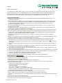
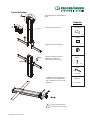
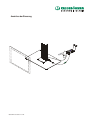
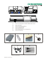
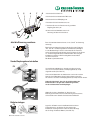
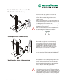
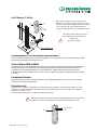
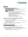
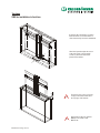
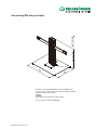
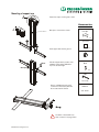
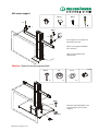
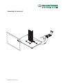
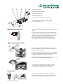
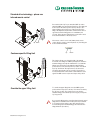
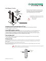
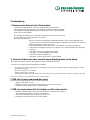
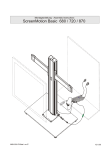
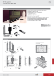
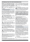
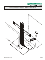
Montageanleitung · Assembly Instructions
ScreenMotion Basic 680 / 720 / 870
889012120 U76 Seite 1 von 26
12.08.08
Vorwort
Sehr verehrter Kunde,
mit der Wahl des ScreenMotion-Basic haben sie sich für eine technisch hochentwickelte und leistungsstarke elektromotorische
Führungssäule entschieden. Ihr ScreenMotion-Basic ist bei uns mit größter Sorgfalt und Präzision hergestellt worden und hat
zahlreiche Qualitäts- und Sicherheitskontrollen durchlaufen, um einen störungsfreien und sicheren Betrieb zu gewährleisten.
Sie selbst können wesentlich dazu beitragen, dass Sie mit Ihrem ScreenMotion-Basic lange Zeit zufrieden sind.
Wichtige Sicherheitshinweise
1. Der Aufbau und die Bedienung der elektromotorischen Führungssäule muss gemäß der Montageanleitung erfolgen, sonst
besteht Verletzungsgefahr!
2. Die Führungssäule ist ausschließlich für den Verwendungszweck als Entertainmentlösung für Wohn-, Schlaf- und Konferenzmöbel, entsprechend den angegebenen Gewichten und Maßen, in dieser Montageanleitung geeignet. Jede darüber hinausgehende Verwendung gilt als nicht bestimmungsgemäß, für hieraus resultierende Schäden haftet der Hersteller nicht.
Das Risiko hierfür trägt allein der Nutzer.
3. Vor dem Abwärtsbetrieb muss der Freiraum in der Möbelbox überprüft werden. Es dürfen sich keine Personen, Tiere oder
Gegenstände darin befinden.
4. Einhaltung Emissionsklasse 1 für Plattenmaterialien, keine Freisetzung von Schadstoffen gem. Sicherheitsdatenblatt, keine
Freisetzung von Schadstoffen in gefahrdrohender Konzentration.
5. Zur bestimmungsgemäßen Verwendung gehört auch die Einhaltung der vom Hersteller vorgeschriebenen Montageanweisung.
6. Berücksichtigen Sie auch die allgemein gültigen, gesetzlichen und sonstigen Regelungen und Rechtsvorschriften - auch des
Betreiberlandes - sowie die gültigen Umweltschutzbestimmungen! Die örtlichen gültigen Bestimmungen der Berufsgenossenschaften oder sonstiger Aufsichtsbehörden sind immer zu beachten!
7. Eigenmächtige Veränderungen am ScreenMotion-Basic schließen eine Haftung des Herstellers für daraus resultierende
Schäden aus.
8. Öffnen Sie nie das Gehäuse der Steuerung! Durch unbefugtes Öffnen des Gehäuses und unsachgemäße Reparaturen können
Gefahren für die Benutzer entstehen und der Gewährleistungsanspruch erlischt.
9. Reparaturen dürfen ausschließlich vom Personal des Herstellers oder von beauftragten Personen durchgeführt werden!
10. Flüssigkeiten dürfen nicht in das Innere der Steuerung und der Hubsäule gelangen. Dies führt zu Kurzschlüssen und
Zerstörung der Steuerungselemente. Steuerungen dürfen nur in geschlossenen Räumen eingesetzt werden
vor Feuchtigkeit schützen.
11. Die Steuerung und die Hubsäule darf ausschließlich zu dem in dieser Bedienungsanleitung vorgegebenen Zweck eingesetzt
werden!
. dies der Fall sein sollte, nehmen Sie das Gerät
12. Überprüfen Sie zuerst, ob die Kabel oder die Gehäuse beschädigt sind. Wenn
nicht in Betrieb, sondern tauschen Sie es bei Ihrem Servicepartner um
13. Die Steuerung und die Hubsäule eignet sich nur für den Betrieb in geschlossenen und trockenen Wohn- und Büroräumen. Sie
dürfen nicht im Freien eingesetzt werden.
14. An der geschalteten Kupplung (Steckdose) dürfen keine Geräte mit einer Leistung von mehr als 800 Watt angeschlossen werden!
15. An der geschalteten Kupplung (Steckdose) dürfen keine elektrischen Heizungen, Heizlüfter, Radiatoren oder elektrische Werkzeuge wie z. B. Bohrmaschinen , Stichsägen oder ähnliches angeschlossen werden!
16. Mit der Steuerung dürfen nur Kesseböhmer Antriebe betrieben werden.
17. Klemm- und Quetschgefahr durch Einhaltung der Abstände zu Gegenständen im Umfeld ausschließen.
Wichtige Hinweise bei Inbetriebnahme
- Die Steckdose zum Anschluss an das Netz muss von einer konzessionierten Elektofachkraft installiert worden sein, um
Gefahren für Personen und Sachen auszuschließen.
- Sorgen Sie jederzeit für freien Zugang zur Steckdose.
- Der Montageort sollte trocken, staubfrei und ohne direkte Sonneneinstrahlung sein.
- Die Umgebungstemperatur zum Betrieb der Steuerung darf + 5°C nicht unterschreiten und +35°C nicht überschreiten.
- Montieren Sie daher die Steuerung:
- nicht über oder vor Wärmequellen ( z. B. Heizkörper),
- nicht an Stellen mit direkter Sonneneinstrahlung,
- nicht hinter Vorhängen,
- nicht in kleinen, unbelüfteten, feuchten Räumen,
- nicht auf oder in der Nähe von leicht entzündlichen Materialien
- und nicht in der Nähe von Hochfrequenzgeräten (z. B. Sender, Bestrahlungsgeräte oder ähnliche Geräte).
- bei Qualmentwicklung am Gerät, bitte den Netzstecker ziehen.
- Die Buchsen zum Anschluss der Motoren sowie des IR-Empfängers dürfen nicht verdeckt werden.
- Achten Sie darauf, dass die Anschlusskabel nicht geknickt, gezogen oder mechanisch belastet werden.
- Zum Schutz gegen Überspannungen, wie sie bei Gewittern auftreten können, empfiehlt sich die Installation eines Überspannungsschutzes.
- Lassen Sie sich von Ihrem Elektroinstallateur beraten.
Wenn Sie diese Hinweise stets beachten, werden Sie am ScreenMotion-Basic lange Freude haben.
Für Rückfragen stehen wir Ihnen gerne beratend zur Verfügung.
889012120 U76 Seite 2 von 26
Varianten
SME für Einbau im Möbel
Umlaufend ist ein Mindestabstand
von 25 mm zwischen eingebautem
Bildschirm und Möbel oder sonstigen
baulichen Einrichtungen einzuhalten.
Nach Inbetriebnahme den Bildschirmträger über die Befestigunsschrauben (1)
ausrichten und die Parallelität zum Möbel
berücksichtigen.
1
<4
1
Die Bildschirmunterkante darf
max. 4 mm über die Oberkante
des Möbels ausgefahren werden.
!
!
889012120 U76 Seite 3 von 26
Geeignete Befestigung im Möbel.
Standsicherheit nach DIN Fb 147
702 / 742 / 892
680 / 720 / 870
Freistehender SME mit Bodenplatte
700
500
Wird die als Zubehör erhältliche Bodenplatte 700x500 mm nicht
verwendet, muss stattdessen eine Platte gleicher Größe mit
mind. 22 kg Gewicht montiert werden.
Achtung:
Fußsteller muss auf einem planen Untergrund ausgerichtet werden.
Artikel-Nr. Bodenplatte: 889010903
889012120 U76 Seite 4 von 26
Tragarm befestigen
Flauschband über die Führungssäule
kleben
A
20
Zubehör
A
Filzstück auf die Säule kleben
Flauschband
1x
Filzstück
1x
Tragarme in die Nuten einführen
M6x16
Filzstück
Tragarme mit den 4 Schrauben
M6x16 mit dem SW4 auf
gewünschter Höhe befestigen.
M6x16
4x
SW 4
max. 15 Nm
4 x M6x30 aus der Führungssäule
schrauben und die Standplatte mit
den 4 Schrauben und dem Torx 30
verbinden.
!
889012120 U76 Seite 5 von 26
Nur im liegenden Zustand
montieren oder demontieren!
TORX 30
max. 15 Nm
Bildschirmträger befestigen
M5x10
M6x12
justieren
2 x
2 x
fixieren
M5x10
M6x12
justieren
fixieren
Träger mit Bildschirm verschrauben
und auf die Arme setzen/hängen.
.
Die Bildschirmträger mit M5x10 und
Schraubendreher justieren.
M6x12 an den Trägerarmen festdrehen.
Achtung: Optional mit Bodenplatte
12x6,4
M6
M6x25
4x
4x
4x
M6x25
Die Standplatte wie abgebildet mit
den 4 Schrauben M6x25 an der
Bodenplatte befestigen.
12x6,4
M6
889012120 U76 Seite 6 von 26
Anschluss der Steuerung
889012120 U76 Seite 7 von 26
D
C
B
A
F
G
E
A
B
C
D
E
F
G
Buchse für die Führungssäule ScreenMotion SME Basic 680 / 720 / 870
Buchse ohne Funktion
Buchse für Tisch-Handschalter TMU 10
Buchse für IR-Empfänger SME
Buchse für Sicherheits-Sensor
Buchse für Kupplung (Steckdose) mit Kaltgerätestecker
Buchse für den Netzstecker
C
Kompaktsteuerung SME
IR Fernbedienung (AUF-AB)
F
Geschaltete Kupplung (Steckdose) mit
Kaltgerätestecker (Länderspezifisch)
889012120 U76 Seite 8 von 26
D
Handschalter TMU10 (AUF-AB)
G
Netzkabel Kompaktsteuerung
IR-Empfänger SME
D
C
A
F
G
A: Schließen Sie die Säule an.
C: Schließen Sie den Handschalter TMU 10 an.
D: Schließen Sie den IR-Empfänger an.
E: Schließen Sie den Sicherheitssensor an.
F: Schließen Sie nun den Fernseher an die geschaltete
Kupplung (Steckdose) an.
G: Stecken Sie das Netzkabel zuerst in die
Steuerung und dann in die Steckdose.
E
Jetzt die Steuerung resetieren
F1
Bevor Sie das Gerät benutzen können, ist ein „Reset” der Steuerung
notwendig.
Bitte drücken und halten Sie dazu gleichzeitig die beiden Pfeiltasten
"Auf" und "Ab". Der Beschlag fährt nun mit halber Geschwindigkeit
in seine Grundstellung. In dieser Position halten Sie die Tasten für
weitere drei Sekunden gedrückt. Nach dieser Zeit lassen Sie die Tasten
los, ein Dreiton-Signal ist akustisch wahrzunehmen. Dieses Signal
bestätigt Ihnen das Reset. Der Beschlag fährt nun automatisch
ca. 3-5 mm nach oben.
Das Gerät ist jetzt betriebsbereit.
Sende-/Empfangskanal einstellen
F2
Um zwei Geräte unabhängig von einander zu bedienen, können
diese auf 2 verschiedene Sende- und Empangskanäle (A und B)
eingestellt werden (siehe Abb. F2).
Hierzu sind im Batteriefach des Handsenders sowie an der vorderen
Stirnseite des IR-Empfängers kleine Schiebeschalter vorgesehen,
mit denen Sie die Sende- und Empfangskanäle (A und B) einstellen können.
Achten Sie bitte darauf, dass sich der Schiebeschalter des
IR-Handsenders in der gleichen Schaltstellung befindet,
wie der Schiebeschalter am IR-Empfänger.
Wählen Sie für das 1. Gerät Kanal A. Wenn Sie ein 2.
Gerät im gleichen Raum mit einer Fernbedienung steuern möchten,
stellen Sie bitte am 2. Gerät die Schiebeschalter auf Kanal B.
i
Batterie einlegen
F3
889012120 U76 Seite 9 von 26
Legen Sie die Batterie zuerst in das Batteriefach der Infrarot
Fernbedienung ein, und drücken Sie diese dann an der
Kontaktseite vorsichtig herunter. Achten Sie dabei unbedingt
auf die richtige Polarität der Batterie (siehe Abb. F3).
Standard-Verfahrtechnik verwenden Sie
bitte die Infrarot-Fernbedienung
Halten Sie die Taste "Auf" gedrückt, um den SME auszufahren. Um den SME wieder einzufahren halten Sie
die Taste "Ab" gedrückt. Der Beschlag kann von der
untersten Position (Grundstellung) bis zum Maximalhub
verfahren werden.
Wenn Sie den Beschlag nach oben oder unten verfahren und
den Beschlag kurz stoppen und ihn dann in der gleichen oder
in entgegengesetzter Richtung verfahren, legt der Beschlag
eine Zwangspause von 2-3 Sekunden ein.
Diese Zeit benötigt die Steuerung um eine Fehlauslösung des
Sicherheitssensors zu vermeiden.
Ab
!
Auf
Wenn die Fernbedienung keine Funktion hat (Batterie leer,
Fernbedienung defekt, Fernbedienung verlegt usw.), können
Sie den Beschlag mit dem Handschalter verfahren.
Ab
Auf
Kundenspezifische Hub-Begrenzung
bb
eg
ren
zu
Diese Funktion ermöglicht es Ihnen, die Ausfahrhöhe
des Beschlags zu begrenzen. Der SME ist werkseitig
auf den maximal möglichen Hub eingestellt. Wenn Sie
wollen, dass der Beschlag an einer Position unterhalb
des Maximalhubs stoppt, fahren Sie diesen mit den
Pfeiltasten "Auf" und "Ab" zu der gewünschten Position.
Drücken Sie nun drei mal die Taste "S" und danach
einmal die Taste "Auf".
708/748/898
ng
680/720/870
Hu
Ab
Auf
Diese Position ist jetzt gespeichert, was von der Steuerung
mit einem akustischen Signal bestätigt wird. Der SME wird
nur noch bis zu dieser Position verfahren.
S
Zum Überfahren der oberen Hubbegrenzung verfahren Sie
den SME bis dieser stoppt. Drücken Sie jetzt sechs mal
die Taste "S" und anschließend die Taste "Auf". Die Säule
fährt jetzt mit halber Geschwindigkeit bis zum Maximalhub
weiter, so lange Sie die Auf-Taste gedrückt halten.
Überfahren der oberen Hubbegrenzung
!
889012120 U76 Seite 10 von 26
Sobald eine einmal eingestellte Hubbegrenzung unterschritten
wird, ist diese wieder aktiv, auch wenn Sie zuvor überfahren
wurde. Um die Werkseinstellung oder eine andere gewünschte
Position wiederherzustellen, fahren Sie den Beschlag bis zum
Maximalhub aus und speichern Sie die Hubbegrenzung hier
neu. (siehe oben)
Auto- Memory- Funktion
Diese Funktion ermöglicht Ihnen ein automatisches
anfahren von der obersten und untersten Position Ihres
Fernsehers. Durch ein zweimaliges drücken der Pfeiltaste
"Auf" sowohl auch "Ab", kann die Grundhöhe und
die oberste eingestellte Hub-Position angefahren werden.
2x
2x
Ab
Auf
Auto-Memory-Funktion darf nur mit einem
Sensorauffahrschutz verwendet werden.
!
Geräteschutz
= Kein Personenschutz
Sensorauffahrschutz
Automatisches Ein- und Ausschalten des Fernsehers
Die im Set enthaltene Kupplung kann an die Steuerung angeschlossen werden und wird von dieser automatisch geschaltet.
Siehe Seite 9, Darstellung der Steuerung/ Buchse „F“
Variante Einbau SME im Möbel
Die Stromzufuhr wird ca. 80 mm oberhalb der unteren Position eingeschaltet. Wird der ScreenMotion bis mindestens 80 mm
unterhalb der oberen Position (Maximalhub oder Hubbegrenzung) verfahren, bleibt die Stromzufuhr aktiviert. Wird der
ScreenMotion nicht komplett ausgefahren (z.B. nur den halben Hub), deaktiviert die Steuerung die Stromzufuhr aus
Sicherheitsgründen nach einer Minute. Auf diese Weise werden ein Hitzestau und daraus resultierende Schäden am Gerät
vermieden.
Freistehende Variante
Die Stromzufuhr wird ca. 80 mm oberhalb der unteren Position eingeschaltet. Wird diese Position wieder unterschritten
unterbricht die Steuerung die Stromzufuhr.
Kindersicherung
Halten Sie 10 sec. die Taste "S" (3)gedrückt, um die Kindersicherung zu aktivieren. Die Steuerung bestätigt ihnen diesen
Vorgang mit einem Zweiton-Geräusch. Das Gerät nimmt nun keine Fahrbefehle mehr an. Zum deaktivieren drücken Sie
erneut 10 sec. die Taste "S" (3).
Die Steuerung bestätigt Ihnen den Vorgang mit einem Einton-Geräusch.
!
Während die Kindersicherung aktiv ist, wird bei jeder Betätigung der Taste ein akustisches
Geräusch von der Steuerung abgegeben, bis der Schutz wieder aufgehoben wird.
Ab
889012120 U76 Seite 11 von 26
Taste "S" (3)
Auf
Fehlerbehebung
1. Steuerung funktioniert nicht; Allgemeine Prüfung
-
-
Rote LED der Infrarot-Fernbedienung leuchtet nicht, wenn man eine Taste drückt?
Prüfen Sie, ob die Batterie richtig eingelegt wurde oder wechseln Sie ggf. die Batterie! Wenn nach dem Wechsel die LED
nicht leuchtet, ist die Fernbedienung defekt. Bitte rufen Sie Ihren Servicepartner an.
Die rote LED der Infrarot-Fernbedienung leuchtet beim Drücken einer Taste und die Steuerung „piepst“ nicht, es
ist aber keine Funktion vorhanden?
Überprüfen Sie:
o Testen Sie, ob Sie mit dem Handschalter den Beschlag nach oben oder unten verfahren können. Wenn
ja, befinden sich die Codierschalter am Sender und Empfänger in der gleichen
Schalterstellung? (siehe Seite 9 Sende- und Empfangskanal einstellen)
o Stellen Sie sicher, dass der IR-Empfänger nicht verdeckt ist.
o Ist der Handschalter TMU 10 und der IR-Empfänger in der richtigen Buchse (siehe Seite 9)
o Ist der Sicherheitssensor eingesteckt? (Falls in dem Lieferumfang kein Sicherheitssensor mitgeliefert
worden ist, ist dieser Punkt nicht relevant)
o Ist das Netzkabel an der Steuerung korrekt eingesteckt?
o Ist der Netzstecker an der Steckdose korrekt eingesteckt?
o Liefert die Steckdose Strom bzw. ist sie eingeschaltet?
o Wenn der Fehler weiterhin besteht, verständigen Sie bitte Ihren Servicepartner.
2. Steuerung funktioniert nicht, es ertönt ein akustisches Signal (Piepston)
Die Steuerung muss zuerst resetiert werden. (Siehe Seite 9, Steuerung resetieren)
Falls das Reset nicht erfolgreich ist können folgende Gründe vorliegen:
- Steuerung befindet sich in der Einschaltdauer, d.h. Beschlag ist länger als zwei Minuten verfahren worden. Beschlag macht
eine Pause von 18 min. versuchen Sie es dann erneut.
- Überprüfen Sie, ob die Kindersicherung aktiviert ist.
- Bitte überprüfen Sie die Steckverbindungen.
- Bei Stromausfall während des Fahrens, muss die Steuerung neu resetiert werden (siehe Seite 9, Steuerung resetieren).
Wenn die Steuerung noch immer nicht funktioniert, verständigen Sie bitte Ihren Servicepartner.
3. SME fährt kurz an und bleibt dann stehen
Resetieren Sie die Steuerung (Siehe Seite 9, Steuerung resetieren)
o Der IR-Empfänger kann verdeckt sein
o Überprüfen Sie die Steckverbindung des IR-Empfängers und ggf. die anderen Steckverbindungen
o Wenn der Fehler weiterhin besteht, verständigen Sie Ihren Servicepartner.
4. SME lässt sich mit Handschalter bewegen mit Fernbedienung jedoch nicht
o
o
o
Überprüfen Sie ob die Kanaleinstellung des IR-Empfängers und der Infrarot-Fernbedienung übereinstimmen. (Siehe Seite 9 ,
Sende-/ Empfangskanal einstellen)
Bitte überprüfen Sie, ob der IR-Empfänger verdeckt ist. Wenn ja, bitte Abdeckung entfernen.
Wenn der Fehler weiterhin besteht, verständigen Sie Ihren Servicepartner.
889012120 U76 Seite 12 von 26
5. Rückhub beim Verfahren
Der Beschlag stoppt während der Fahrt und fährt einige mm in die entgegengesetzte Richtung. Hierbei handelt es sich um
eine Auslösung des Auffahrschutzes.
Mögliche Ursachen:
o Kabel zu kurz
o Schwanken des Bildschirms
o Gegenstand im Verfahrweg
!
!
§
Funktion Sicherheitssensor
Nach Beginn jeder Fahrt wird der Sensor erst nach einer Sekunde aktiv.
§
Nach dem Auslösen des Sicherheitssensors ist eine Pause von
ca. 5 Sek. einzuhalten, bis sich die Schwingung des Beschlags aufhebt.
6. Säule bleibt im ausgefahrenen Zustand stehen
Aus wartungstechnischen Gründen bleibt die Säule nach 10000 Hüben im
ausgefahrenen Zustand stehen. Bitte rufen Sie ihren Servicepartner an.
Technische Änderungen vorbehalten.
889012120 U76 Seite 13 von 26
Foreword
Dear customer,
In choosing a ScreenMotion Basic model, you have decided to acquire a technically advanced and powerful motor-driven guide
column.Your ScreenMotion Basic has been manufactured inhouse with the utmost care and precision and has passed numerous
quality and safety checks to ensure trouble-free and safe operation. You can significantly contribute to your long-term satisfaction
with your ScreenMotion Basic model.
Important Safety Information
1. Assembly and operation of the motor-driven guide column must be in accordance with these assembly instructions –
otherwise there is a risk of injury!
2. The guide column is solely intended to serve as an entertainment solution for living room, bedroom and conference room furniture in
accordance with the weights and measures given in these instructions. Any usage other than that mentioned above is inappropriate;
the manufacturer disclaims liability for any resulting damages. In such cases all risk is carried by the user.
3. Before any downward movement the space in the furniture compartment must be checked. There must not be any persons,
animals or objects in the compartment.
4. Compliant with emission class 1 for particleboards. No emission of harmful substances pursuant to Safety Data Sheet; no
emission of harmful substances in harmful concentrations.
5. The intended operation of the device implies compliance with the assembly instructions stipulated by the manufacturer.
6. Please also take into account the general legal and other regulations and legal provisions that are applicable – including
those that apply in the operator’s country - as well as the applicable environmental protection regulations. The regulations of
trade associations or other supervisory authorities that are in force locally must always be observed!
7. The manufacturer cannot be held responsible for any losses or damage resulting from unauthorised modifications to the
ScreenMotion Basic.
8. Never open the control unit housing! As a result of unauthorised opening of the housing and improper repairs dangers can
arise for the user and the guarantee claim expires.
9. Repairs may only be carried out by personnel working for or licensed by the manufacturer!
10. Do not allow any liquid to penetrate the inside of the control unit or the lift column. This could lead to short circuiting and
destruction of control elements. Controls may only be operated in enclosed areas. Do not use in humid environments.
11. The control unit and lift column may only be used for the purposes outlined in these assembly instructions.
12. Please first check whether cable or housing are damaged. In this case do not operate the device but have it replaced by
your service partner.
13. The control unit and lift column are only suitable for operation in enclosed and dry living and office rooms. They may not be
used outdoors.
14. Do not connect electric devices with a power consumption of over 800 watts to the live outlet (socket).
15. Do not connect electric heating devices, fan heaters, radiators or power tools such as drills, jigsaws or similar devices to
the live outlet (socket).
16. The control unit may only be used for the operation of Kesseböhmer drives.
17. Keep other objects away to eliminate any danger of jamming or crushing them.
Important notice for Start-up operation
- The socket for connection with the mains must be installed by a licensed electrician in order to avoid any hazard to persons
or objects.
- Make sure that the socket is accessible at all times.
- The assembly site should be dry, dust-free and not in direct sunlight.
- The ambient temperature for operation of the control unit must not go below +5°C or above +35°C.
- For these reasons do not assemble the control unit:
- above or in front of heat sources (e. g. heaters),
- in places exposed to direct sunlight,
- behind curtains,
- in small, unaired, damp rooms,
- on or near easily flammable materials or
889012120 U76 Page 14 of 26
- near high frequency equipment (e. g. transmitters, radiation equipment or similar devices).
- If the device emits smoke, please unplug the power cord.
- The socket for connecting the motors and the IR-receiver must not be covered.
- Make sure the connecting cables are not kinked, pulled or mechanically strained.
- For protection against power surges, e.g. during thunderstorms, the installation of surge protection is recommended.
- Ask your electrician for advice.
Provided the above guidelines are adhered to, you will enjoy many years of satisfaction from your ScreenMotion Basic. For
any further enquiries please do not hesitate to contact us.
889012120 U76 Page 15 of 26
Versions
SME for installation in furniture
A minimum all-round distance of 25 mm
between built-in screen and furniture or
other structural objects must be maintained.
After initial operation adjust the screen
support by means of the fastening
screws (1) and ensure that it runs
parallel to the furniture.
1
<4
1
The bottom edge of the screen may
not project more than 4 mm above
the top edge of the furniture.
!
!
889012120 U76 Page 16 of 26
Appropriate mount in the furniture.
Stability in accordance with
DIN Fb 147.
702 / 742 / 892
680 / 720 / 870
Free-standing SME with ground plate
700
500
Should the ground plate 700x500 mm, which is available as an
accessory, not be used, a plate of the same size having a minimum
weight of 22 kg must be mounted.
Attention:
Set screws must be adjusted on a plane surface.
Item no for the ground plate: 889010903
889012120 U76 Page 17 of 26
Mounting of support arm
Fasten fleece tape over the guide column.
A
20
Accessories
A
Glue piece of felt onto the column.
fleece tape
1x
piece of felt
1x
Insert support arms into the grooves.
.
M6x16
Glue piece
Affix the support arms by means of the
4 M6x16 screws and the SW4 allen
key to the desired height.
M6x16
4x
SW 4
max. 15 Nm
Remove 4 x M6x30 from the guide
column and connect base plate with
the 4 screws and the Torx 30.
TORX 30
max. 15 Nm
!
889012120 U76 Page 18 of 26
Assemble or disassemble only
when column is in a lying position!
Affix screen support
M5x10
M6x12
adjust
2 x
2 x
fix
M5x10
M6x12
adjust
fix
Screw together screen support and
place/hang on the arms.
.
Adjust screen supports with M5x10
and screw driver.
Tightly screw down M6x12 at the
supporting arms.
Attention: Optional mounting to ground plate
12x6,4
M6
M6x25
4x
4x
4x
M6x25
Mount base plate with 4 M6x25 screws
to the ground plate as shown in the
illustration.
12x6,4
M6
889012120 U76 Page 19 of 26
Connecting the control unit
889012120 U76 Page 20 of 26
D
C
B
A
F
G
E
A
B
C
D
E
F
G
Jack for guide column ScreenMotion SME Basic 680 / 720 / 870
Jack without function
Jack for tabletop handset TMU 10
Jack for IR receiver SME
Jack for safety sensor
Jack for outlet (socket) with IEC connector
Jack for mains plug
C
Control unit SME
IR Remote control (up/down)
F
Switched mains socket (Country specific)
889012120 U76 Page 21 of 26
D
Handset TMU 10 (up/down)
G
Mains connection cable
IR Receiver SME
D
C
A
F
G
A: Connect the column.
C: Connect the handset TMU 10.
D: Connect the IR receiver.
E: Connect the safety sensor.
F: Connect the TV set to the live outlet (socket).
G: Connect the mains cable with the control unit first
and then with the socket.
E
Now reset the control unit
F1
Before the device is ready for operation the control unit needs to be
reset.
In order to reset the control unit, press and hold both arrow keys
“Up” and “Down”. The fitting moves into its home position at half
speed. Keep the keys pressed for another three seconds in this
position. After the time has expired release the keys and a
three-tone signal can be heard. Now the fitting automatically
moves up ca. 3-5 mm. The device is now ready to operate.
Adjust send/receive channels
F2
In order to operate two devices independently of each other,
they can be adjusted to function on 2 different send and receive
channels (A and B) (See fig. F2).
For the purpose of selecting send and receive channels (A and B)
there are two sliding switches located in the battery compartment
or the handset and at the front end of the IR receiver.
Please make sure that the sliding switch in the IR handset is in the
same position as the sliding switch at the IR receiver.
Select channel A for the first device. If you want to operate a
second device in the same room with the same remote set
the sliding switch on the second device at channel B.
i
Insert battery
F3
889012120 U76 Page 22 of 26
First insert battery in the battery compartment of the infrared
remote control and press it down carefully on the contact side.
Be sure to insert the battery with the correct polarity (see fig. F3).
Standard drive technology - please use
infrared remote control
Press and hold the “Up” key to extend the SME. In order to
retract the SME, press and hold the “Down” key. The fitting can
be moved from the bottom position (home position) to the
topmost lifting position. If the up or down movement of the
fitting is interrupted shortly and then continued in the same or
opposite direction the fitting pauses for a mandatory 2-3
seconds. This is the time required by the control unit to avoid
an accidental activation of the safety sensor.
Up Down
!
Up
gl
im
it
Down
This function allows you to limit the height of the upward
movement of the fitting. The SME is pre-adjusted to reach the
maximum lifting position by the manufacturer. If you want the
fitting to stop at a position lower than the maximum lifting
position move it to the desired position by means of the arrow
keys “Up” and “Down”. Now press the key “S” three times
followed by pressing the “Up” key one time. This position is
now saved which the control unit will confirm with an acoustic
signal. The SME can now only be moved up to this position.
708/748/898
tin
680/720/870
Costomer-specific lifting limit
Lif
If the remote control is out of order (battery dead, remote
control defective, remote control misplaced, etc.) the fitting can
be moved with the handset.
Up Down S
Override the upper lifting limit
To override the upper lifting limit, move the SME up to the
position where it stops. Press the key “S” six times followed by
the “Up” key one time. The column moves now up to the
maximum lifting position at half speed as long as you keep the
“Up” key pressed.
!
889012120 U76 Page 23 of 26
As soon as the fitting reaches a position that is below the saved
lifting limit it is reactivated even if it was previously overridden.
To restore the factory setting or any other desired position
move the fitting to the maximum lifting position and save the
lifting limit anew. (See above)
Auto- Memory- Function
2x
2x
Up
This function allows an automatic movement from the top
and bottom position of your TV set. By pressing the arrow
keys “Down” and “Up” twice the bottom height and the
topmost adjusted lifting position can be reached.
Down
The Auto Memory Function may only be used in
combination with an elevation protection sensor.
!
Device protection
= No operator
Elevation protection sensor
Automatic activation and deactivation of TV set
The outlet included in the set can be connected with the control unit and will then be automatically activated by it.
See page 9, illustration of control/ Jack “F”
Variant SME installed in furniture
The power supply is activated ca. 80 mm above the bottom position. If the ScreenMotion is moved to at least 80 mm below
the top position (maximum lifting position or lifting limit), the power supply remains activated. If the ScreenMotion is not
completely extended (e.g. only halfway), the control unit deactivates the power supply for safety reasons after one minute.
Thus heat accumulation and any damages to the device resulting from it are prevented.
Free-standing variant
The power supply is activated ca. 80 mm above the bottom position. If the fitting reaches a position below this point the
control unit interrupts the power supply.
Child-proof lock
Press and hold the "S" key (3) for 10 sec. to activate the child-proof lock. The control unit confirms this for you by producing
a two-tone sound. From now on the device will not accept any movement commands. To deactivate, press the "S" key (3)
again for 10 sec.
The controlunit confirms this for you by producing a one-tone sound.
While the child-proof lock is activated each time a key is pressed it will produce an acoustic signal from the control unit until
the protection is deactivated.
!
While the child-proof lock is activated each time a key is pressed it will produce an acoustic signal from
the control unit until the protection is deactivated.
“S” key (3)
Up
889012120 U76 Page 24 of 26
Down
Troubleshooting
1. Remote control does not work; General check
- Red LED on the infrared remote control does not light up while a key is pressed?
Check if battery has been inserted correctly, otherwise you may have to replace the battery!
If the LED does not light up after battery has been replaced, the remote control is defective.
Please call your service partner.
- The red LED on the infrared remote control lights up when key is pressed and the control unit
does not make a one-tone sound but there is no function?
Execute the following checks:
o Check if you can move the fitting up and down with the handset. If yes, are the sliding switches at
sender and receiver in the same position? (See page 22 for adjustment of send and receive channels.)
o Make sure that the IR receiver is not covered.
o Are the handset TMU 10 and the IR receiver connected with the correct jack? (See page 22.)
o Is the safety sensor plugged in? (If the scope of delivery does not include a safety sensor, this point is
irrelevant.)
o Is the power cord correctly plugged in at the control?
o Is the power cord correctly plugged in at the mains?
o Is the socket live and is it switched on?
o If the failure continues, please inform your service partner.
2. Control unit does not work, acoustic signal (beeping tone) can be heard
The control unit must be reset first. (See page 22 for how to reset the control unit)
If a reset is not successful, the following reasons can apply:
- The control unit is in it`s starting-up phase, e.g. fitting has been moved for more than two minutes. Fitting will pause for 18 min.
Try again after the pause.
- Check if the cild-proof lock is activated.
- Please check the plug connections.
- Should a power outage occur whille moving, the control unit must be reset anew (See page 22 for how to reset the control unit.)
If the control unit still does not work please inform your service partner.
3. SME starts to move and immediately stops
Reset the control unit (See page 22 for how to reset the control unit.)
o The IR receiver may be covered.
o Check the IR receiver’s plug connection and all other plug connections if necessary.
o If the failure continues, please inform your service partner.
4. SME can only be moved with the handset, not with remote control
o Check if the channel settings of IR receiver and infrared remote control are in accordance.
(See page 22 for adjustment of send and receive channels.)
o Please check if the IR receiver is covered. If yes, remove cover.
o If the failure continues, please inform your service partner.
889012120 U76 Page 25 of 26
5. Return movement
The fitting stops and moves some mm in the opposite direction. This happens when the elevation protection is activated.
Possible reasons:
o Cable is too short
o Screen sways
o Object is in the way
!
!
•
Function of safety sensor
The sensor is activated ca. one second after the start of any movement.
•
After the safety sensor is activated a pause of ca. 5 sec. needs to be observed until the swaying of
the fitting stops.
6. Column remains in extended position
For maintenance reasons the column remains extended after 10,000 lifts. Please call your service partner.
Subject to change without notice.
Kesseböhmer Ergonomietechnik GmbH
Siemensstrasse 6 · D-73235 Weilheim/Teck
Tel:+49(0)7023-7454-0 · Fax:+49(0)7023-7454-3200
eMail: [email protected] · www.kesseboehmer.de
889012120 U76 Page 26 of 26