1
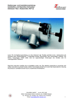
Gasaufbereitung testo 339
Bedienungsanleitung
Instruction manual
de
en
Gasaufbereitung für Dauermessungen
an Industrie-Feuerungsanlagen
Inhalt
Beschreibung ............................................................................................3
Warum eine Gasaufbereitung................................................................3
Funktionsprinzip....................................................................................3
Warnhinweise ...........................................................................................4
Frontansicht...............................................................................................5
Beschreibung Leuchtdioden.....................................................................6
Ansicht Geräterückseite............................................................................7
Inbetriebnahme..........................................................................................8
Messung...................................................................................................10
Normalbetrieb/Automatikbetrieb .........................................................10
Betrieb der Gasaufbereitung ohne
Beheizung des Gasentnahmeschlauches (Sonderbetrieb) ...................11
Zugmessung in Verbindung mit testo 33 ............................................11
NO -Messung .....................................................................................11
2
Betriebszustände.....................................................................................12
Einschaltphase....................................................................................12
Betriebsphase.....................................................................................12
Reinigungsbetrieb ...............................................................................13
Betrieb der Gasaufbereitung ohne
Beheizung des Gasentnahmeschlauches (Sonderbetrieb) ...................13
Störmeldebetrieb ...............................................................................13
Störungen
Ursache und Behebung ......................................................................14
Gasentnahmeschlauch............................................................................16
Reinigung
Gausaufbereitung ...............................................................................17
Gasentnahmeschlauch .......................................................................18
Rauchgassonde..................................................................................18
Wartung
Wechsel der
Lüfterfilter............................................................................................19
Sicherungen .......................................................................................19
Pumpenkassette.................................................................................20
Filterwechsel Gasentnahmeschlauch ..................................................20
Technische Daten....................................................................................21
Bestelldaten ............................................................................................22
Garantie ...................................................................................................22
Meßgerät konform zu
EN 50 082 - 1 / EN 55 011 Gruppe 1 Klasse A,
EN 61 010 - 1
Beschreibung
Warum eine Gasaufbereitung?
Bei Abgas-Messungen an Feuerungsanlagen über einen längeren
Zeitraum führt in der Regel entstehendes Kondensat zu ungenauen
NO2- und SO2-Gehaltsangaben. Zur
Kondensatbildung kommt es, weil
der Wasser- bzw. der Säuretaupunkt
innerhalb des Gasweges
unterschritten wird. Das Kondensat
schlägt sich in Filtern oder in Schläuchen nieder und absorbiert (bindet)
NO2- und SO2--Anteile (die Meßwerte
werden verfälscht).
Funktionsprinzip
Die tragbare Gasaufbereitung testo
339 ist für das RauchgasAnalsengerät testo 33 konzipiert und
wird zwischen der Rauchgas-sonde
und dem Analysegerät
angeschlossen.
Partikelfilter
Schlauch beheizt (2,20 m und 4,0 m Länge)
Innen-Seele (PTFE)
testo 339
Temperaturregelung
Schlauchpumpe
Tygon® - Verbindungsschlauch
zum testo 33 (0,4 m Länge)
Netzteil
90 ... 260 Volt
Anzeige- und
Überwachungselektronik
Gasumschaltventil
testo 33
Die Aufbereitung des Meßgases über
das testo 339 führt zu einer
Reduzierung der Absorption bis auf
ein Minimum. Der beheizte Partikelfilter und der anschließend ebenfalls
beheizte Gasweg halten das Rauchgas auf einer Temperatur von +150
°C - bis das Meßgas im Gaskühler
mittels eines Peltierelmentes auf
einen Taupunkt von +3...+6 ° C
abgekühlt wird. Das dabei entstehende Kondensat wird in das
optionelle Kondensatgefäß abgepumpt. Das bereits gereinigte und
nun auf einen Restfeuchtegehalt
getrocknete Meßmedium wird in dem
Analysegerät des testo 33 analysiert.
TUV.
SUDWEST
geprüfte
Sicherheit
Der Prüfung des Technischen
Überwachungs-Vereins (Bericht
GEM1-GE-17.2/1/1613/92) in Bezug
auf elektrische Sicherheit, Funkstörverhalten, Störfestigkeit Industriebereich (EMV) lagen folgende
Normungen zugrunde:
Elektrische Sicherheit
DIN VDE 0411 Teil 1/10.1973 bzw.
DIN VDE 0411 Teil 1a/02.1980
Funkstörverhalten
PostVfg. 1046 (DIN VDE 0871)
Störfestigkeit Industriebereich
(EMV)
IEC 801 Teil 2, 3, 4, 5
prEN 50 082-2.
3
Warnhinweise
Vor Inbetriebnahme bitte unbedingt lesen und beachten:
Die Gebrauchslage des Geräts ist immer waagrecht.
Das Gerät darf nicht in explosionsgefährdeten Bereichen
betrieben werden.
Beachten Sie die Angaben unter "Technische Daten".
Prüfen Sie anhand des Typenschildes ob Typ, Netzspannung und
Leistung mit den tatsächlichen Gegebenheiten übereinstimmen.
Ein Betreiben des Schlauches in Ausführung 110 V~ an Netzspannung
230 V~ führt zur Zerstörung d. Gasentnahmeschlauches. Der Betrieb
eines Schlauches in 230 V~ Ausführung an 110 V~ Netzspannung führt
nicht zu den notwendigen Solltemperaturen.
Die zulässigen Brennstoffe für die Gasaufbereitung sind:
Heizöl EL, Heizöl S, Erdgas, Flüssiggas, Koks, Brikett,
Braunkohle, Steinkohle, Kokereigas und Stadtgas.
Bei anderen Brennstoffen ist darauf zu achten, daß hochaggressive Stoffe wie z. B. Fluor und Halogenverbindungen
die Werkstoffe des Gaswegs angreifen können.
Die seitlichen Lüftungsschlitze müssen offen liegen. Auf einen
minimalen Zustand von 30 mm zu anderen Gegenständen ist zu
achten. Außerdem sollte das Gerät nicht in kleinen, geschlossenen,
nicht durchlüfteten Gefäßen oder Behältern betrieben werden.
testo 339 erst nach dem Anschluß des Gasentnahmeschlauches
einschalten!
Der Gasentnahmeschlauch sollte keinen Zugbeanspruchungen
ausgesetzt werden und darf nicht von außen erwärmt werden.
Vorsicht! Oberfläche der Schlauchleitung (insbesondere im Bereich
des Filtergehäuses erhitzt sich bei Betrieb.
Bei Befestigung des Gasentnahmeschlauches mit Schellen oder
ähnlichen Teilen muß darauf geachtet werden, daß der äußere Aufbau der
Schlauchleitung nicht zusammengedrückt wird. Wird der
Außendurchmesser um mehr als 10 % verringert, werden Heizleiter,
Steuerleitungen und Fühlerleitungen beschädigt.
Die Umgebungstemperatur darf über die gesamte Schlauchlänge nicht
um mehr als 20 ° C differieren. Um eine zu starke Abkühlung zu vermeiden, muß die Leitung im Freien windgeschützt verlegt werden.
Die Schutzumflechtung der Schlauchseele besteht aus dünnen Drähten,
die zu einem Schlauch geflochten sind. Vermeiden Sie herausragende
Nägel, scharfe Kanten oder ähnliches in der Umgebung des
Gasentnahmeschlauches. Der Schutzmantel und
die Einzeldrähte können dadurch beschädigt werden.
Betreiben Sie den Schlauch grundsätzlich nur mit Partikelfilter!
Betrifft nur die 4m-Ausführung 0401.0395:
Die Kupplungsstelle zwischen Rauchgassondenleitung und
Verlängerungsleitung 0554.0341 muß mindestens einen Abstand
von 15 cm zum beheizten Gasentnahmeschlauch haben, da es
ansonsten zu Fehlmessungen der Raum- und Abgastemperatur kommen
kann.
Gasaufbereitung testo 339
Frontansicht
Gasausgang
bzw. Anschlußverschraubung für den
Verbindungsschlauch zum Analysegerät testo 33.
Gaseingang
Anschluß des Gasentnahmeschlauches (von Rauchgassonde kommend).
elektrische Anschlußbuchse
Gasentnahmeschlauch
POWER
ON
Service-Taster
Service
LED 1
Kondensatpumpenkassette
LED 2
testo 33
LED 3
LED 4
LED 5
LED 6
LED 7
LED 8
LED 9
AUTOMATIC
off on
Ansaugstutzen
AutomatikIm Automatikbetrieb Schalter
wird hier Frischluft zur
Regenerierung bzw.
Kalibrierung der
Zellen angesaugt.
5
testo 339
testo
term
Kondensatausgang
Beschreibung Leuchtdioden (LED)
Die Frontplatte des testo 339 ist mit neun verschiedenfarbigen 8-mmLeuchtdioden bestückt, die den Benutzer über die Betriebsphase bzw.
Betriebszustand des Gerätes informieren.
Die gelben und grünen LED weisen auf einen Betriebszustand hin, während die
roten LED grundsätzlich Warnungs- bzw. Fehlerzustände verdeutlichen.
LED 1: leuchtet ➝ Gerät eingeschaltet
(gelb)
LED 2: Sie gibt an, ob das Gerät betriebsbereit ist und in welchem
(grün) Schaltzustand sich das interne Gasumschaltventil befindet.
erloschen: das Gerät ist nicht betriebsbereit
leuchtet: das Gerät ist betriebsbereit,
der Gasweg ist auf Rauchgas geschaltet.
blinkt:
das Gerät ist betriebsbereit, befindet sich im Automatikbetrieb und das interne Gasumschaltventil ist auf
Frischluft geschaltet.
LED 3: leuchtet ➝ Die Umgebungstemperatur entspricht nicht den
(rot)
zulässigen Werten (siehe Angaben in "Technische Daten").
LED 4: Das Leuchten dieser LED kann verschiedene Ursachen
(rot)
haben:
- Defekt des Gasentnahmeschlauches (führt zur Abschaltung)
- Betrieb der Gasaufbereitung ohne elektrischen Anschluß des
Gasentnahmeschlauches (Sonderbetrieb)
- Unerlaubter Anschluß des Gasentnahmeschlauches im
Reinigungsbetrieb (LED blinkt)
LED 5: leuchtet ➝ die beheizte Schlauchleitung des Gasentnahmeschlauches erreicht nicht mehr die geforderte Temperatur.
Dieser Fehler führt zum Abschalten des Gerätes testo 339.
(rot)
LED 6 : Die Schlauchleitung des Gasentnahmeschlauches wird aufgeheizt.
(gelb)
(LED leuchtet) bis die Betriebstemperatur erreicht ist (LED blinkt).
LED 7: leuchtet ➝ Die Lüfterfilter (Geräterückseite) sind verstopft.
(rot)
Dieser Fehler führt zum Abschalten des Systems.
LED 8: leuchtet ➝ Ein systembedingter Fehler führte zur Abschaltung
(rot)
der Gasaufbereitung.
LED 9: Das Kühlsystem des testo 339 wird mit Spannung versorgt
(gelb)
(LED leuchtet) bis die Betriebstemperatur erreicht ist (LED blinkt).
6
Ansicht Geräterückseite
Sicherungshalterung
Netzschalter
Netzanschluß
Erdungsbuchse
Lüfterfilter
Wartungsschnittstelle
Inbetriebnahme
Zur Inbetriebnahme sind folgende Komponenten erforderlich:
- Gasaufbereitung testo 339
- Netzkabel (testo 339)
- beheizter Gasentnahmeschlauch
- Verbindungsschlauch
(Gasaufbereitung testo 339 -Analysegerät testo 33)
- testo 33 mit Analysegerät und Rauchgas-Sonde
Wir empfehlen zusätzlich:
- Kondensat-Auffanggefäß (Option, siehe Zubehör)
Das Gerät testo 339 erst nach dem Anschluß des Gasentnahmeschlauche einschalten!
POWER
ON
SERVIC
testo 33
testoterm
testo 339
AUTOMATIC
D-7825 Lenzkirch
W
¡C
t
testoterm GmbH
& Co.
Die Gasleitung der Rauchgassonde (rot
gekennzeichnet) wird durch den
beheizten Gasentnahmeschlauch ersetzt.
Am ersten Gasabgang der Rauchgassonde Schlauch abnehmen und den
beheizten Gasentnahmeschlauch
anschließen.
An der Gasaufbereitung Konus der beheizten Schlauchleitung einschieben und
Überwurfmutter mit leichter Handkraft aufschrauben und den elektrischen
Anschluß stecken.
Der Gasweg wird über die Gasaufbereitung testo 339 umgeleitet.
Der im Lieferumfang enthaltene Verbindungsschlauch leitet das Meßgas vom
testo 339 (Gasausgang) zum Gaseingang des Analysegerätes testo 33.
Stellen Sie das Analysegerät auf oder neben die Gasaufbereitung
(Mindestabstand von 30 mm beachten!).
Stecken Sie das Netzkabel des Gasaufbereiters testo 339 in den dafür
vorgesehenen Netzanschlußstecker und schließen Sie das Gerät an das
Stromnetz an. Ist kein Schutzkontakt am Stromnetz vorhanden, muß über die
Erdungsbuchse (Geräterückseite) ein Erdungskontakt hergestellt werden.
POWER
ON
8
testo 33
Inbetriebnahme
Das Kondensat-Auffanggefäß (Option) wird an der Geräteseite einfach eingehängt. Schließen Sie den Schlauch des Kondensat-Auffanggefäßes an den
Kondensat-Ausgang an.
Schalten Sie den Netzschalter (Geräterückseite) in Stellung "I" und schalten
Sie das Handgerät testo 33 ein.
POWER
ON
Service
Die Gasaufbereitung führt zuerst einen Selbsttest durch, wobei ein kurzes
Aufleuchten aller Leuchtdioden den Startvorgang des Geräts signalisiert.
testo 33
AUTOMATIC
testo 339
off on
testo
term
Während der ersten 15 Sekunden nach dem Einschalten pumpt die
Kondensatpumpe eventuell vorhandene Kondensatreste aus dem System.
Danach wird alle 5 Minuten für 15 Sekunden das abgeschiedene Kondensat
abgesaugt.
Je nach Umgebungstemperatur und Eigentemperatur des Gasentnahmeschlauches bzw. des Kühlsystems dauert die darauf folgende Einschaltphase zwischen 6 und 12 Minuten.
Während der Einschaltphase ist das Gasumschaltventil (über das im
Geräteinneren der Gasweg geschaltet wird) generell auf Frischluft geschaltet.
Der Gasentnahmeschlauch und die Kühlung werden auf die
Solltemperaturen gebracht, die entsprechenden LED leuchten bzw.
blinken. In dieser Phase leuchtet die grüne LED 2 für Betriebsbereitschaft
noch nicht. Ein Betätigen des Service-Tasters während der Einschaltphase hat
keine Auswirkung.
Sind die Solltemperaturen des Gasentnahmeschlauch und der Kühlung
erreicht, geht die Gasaufbereitung in die Betriebsphase über, in der nun
gemessen wird. Das Gerät schaltet auch bei gedrücktem Automatikschalter
zuerst auf Rauchgas um. Die grüne LED 2, die über die Betriebsbereitschaft
Auskunft gibt, leuchtet. Je nach Betriebsart (Normal- bzw. Automatikbetrieb)
ist der Verlauf der Messung unterschiedlich.
Ein Betätigen des Service-Tasters während der Betriebsphase hat keine
Auswirkung.
In dieser Betriebsphase ist als einzig rot leuchtende LED das Leuchten der LED
4 erlaubt; sie zeigt hier an, daß der elektrische Anschluß des Gasentnahmeschlauches nicht angeschlossen ist. Alle anderen rot leuchtenden LED
führen sofort zu einer Abschaltung bzw. Deaktivierung des Systems.
9
Messung
Man unterscheidet zwei Betriebsarten: Den Normalbetrieb bzw. den
Automatikbetrieb.
Beim Automatikbetrieb wird in Intervallen von 10 Minuten der Gasweg von
Rauchgas auf Frischluft und umgekehrt umgeschaltet, während beim
Normalbetrieb der interne Gasweg immer auf Rauchgas geschaltet ist.
Der Automatikbetrieb muß dann eingeschaltet werden, wenn das testo 33
über dem Zeitraum von 30 Minuten hinaus messen soll (ansonsten kann es zu
Beschädigungen der Meßzellen kommen). In der Gasaufbereitung befindet sich
ein Gasumschaltventil, das den Gasweg zwischen dem Ansaugstutzen und
dem Gaseingang umschaltet.
Während der Frischluftansaugung können sich die Meßzellen wieder
regenerieren, sodaß ein durchgehender Meßbetrieb bis max. 24 Stunden
für das testo 33 möglich wird.
Die Betriebsart wird über den Automatik-Schalter gewählt. Ist der Schalter
gedrückt, so ist der Automatik-Betrieb angewählt, bei nicht gedrücktem
Schalter ist der Normalbetrieb selektiert. Der Automatikbetrieb beginnt immer
mit einer 10-minütigen Frischluft-Einspeisung (LED 2 blinkt).
Gasumschaltventil
steht auf
Frischluft
(LED blinkt)
Rauchgas
(LED leuchtet)
Zeit in min
Zusätzlich hält dieser Betrieb die Möglichkeit offen, am Ansaugstutzen ein
Prüfgas einzuspeisen, um somit Meßergebnisse kontinuierlich prüfen zu
können.
Bei Automatikbetrieb, sollte darauf geachtet werden, daß bei starker
Luftverschmutzung der Außenluft vor den Ansaugstutzen ein
optionaler Luftfilter montiert werden muß, da starke
Luftverschmutzungen zu Funktionsbeeinträchtigungen des
Meßgerätes führen können.
Der Normalbetrieb kann dann eingesetzt werden, wenn eine zeitlich
begrenzte Messung vorgenommen worden soll bzw. wenn die
Gaskonzentration relativ gering ist (ca. 5-10 % des Meßbereiches).
Um dem Anwender zu zeigen, in welcher Betriebsart sich das Gerät befindet,
dient die grüne Leuchtdiode LED 2.
Man kann mit ihr drei Zustände unterscheiden.
1: Die grüne Leuchtdiode (2) leuchtet nicht.
- Die Gasaufbereitung ist nicht betriebsbereit.
➝ Die Gasaufbereitung befindet sich entweder in der
Einschaltphase, im Reinigungsbetrieb oder ein Fehler ist
aufgetreten (LED 5, LED 7, LED 8 brennt).
2: Die grüne Leuchtdiode (2) leuchtet.
- Die Gasaufbereitung ist betriebsbereit/das Gasumschaltventil
ist auf Rauchgas geschaltet.
10
AutomatikSchalter
gedrückt
10
20
30
40
Messung
Betrieb der Gasaufbereitung ohne Beheizung des Gasentnahmeschlauches (Sonderbetrieb)
Bei NO2- bzw. SO2-Messungen ist ein Betreiben des Meßgerätes ohne
Schlauchheizung (d. h. ohne elektrischen Anschluß des Gasentnahmeschlauches) nicht ratsam. Das wird auch durch das Leuchten der LED 4
signalisiert. Grundsätzlich ist es jedoch möglich.
Zugmessung in Verbindung mit testo 33
Die Schlauchklemme an dem Verbindungsschlauch zwischen Gasaufbereitung und testo 33 muß bei der Zugmessung gedrückt werden. Sie hat die
gleiche Funktion, wie die Schlauchklemme am Sondenschlauch testo 33,
siehe BAL testo 33.
NO2-Messung:
Bei der NO2-Messung sollte darauf geachtet werden, daß der Durchfluß nicht
unter 0,5 l/Minute absinkt. Der Durchfluß kann mit dem testo 33 im Modus
"Service➝ Betriebswerte" überprüft werden. Ist der Durchfluß unter 0,5
l/Minuten abgesunken, sollte zuerst der beheizte Partikelfilter kontrolliert und
gegebenenfalls erneuert werden.
Sollte die Ursache für die niedrige Durchflußmenge (Standard ca. 0,7 Liter/
Minuten) nicht sofort gefunden werden, kann durch schrittweises Abhängen
einzelner Gerätekomponenten der Fehler leichter gefunden werden. Ändert
sich z. B. der Durchfluß nicht, obwohl die Gasaufbereitung vom testo 33
abgehängt wurde, ist die Ursache für den zu niedrigen Durchfluß in der Pumpe
des Analysegerätes zu suchen.
11
Betriebszustände
Für den Benutzer ist es wichtig zu wissen, in welchem Betriebszustand sich die
Gasaufbereitung befindet. Die Betriebszustände werden durch die verschiedenen Leuchtdioden angezeigt.
- die Einschaltphase
Das Gasumschaltventil (über das im Geräteinneren der Gasweg
geschaltet wird) ist generell auf Frischluft geschaltet.
Der Gasentnahmeschlauch und die Kühlung werden auf die
Solltemperaturen gebracht, die entsprechenden LED leuchten bzw.
blinken.
In dieser Phase leuchtet die grüne LED 2 für Betriebsbereitschaft
noch nicht.
- die Betriebsphase
Die Betriebsbereitschaft ist erreicht, wenn sich die Solltemperaturen
für den Gasentnahmeschlauch und für die Kühlung eingestellt haben.
Nur in diesem Betriebszustand darf gemessen werden.
Bei Erreichen der Solltemperaturen nach dem Einschalten schaltet
das Gerät auch bei gedrücktem Automatikschalter zuerst auf
Frischluft um. Die grüne LED 2, die über die Betriebsbereitschaft
Auskunft gibt, blinkt. Je nach Betriebsart (Normal- bzw. Automatikbetrieb) ist der Verlauf der Messung unterschiedlich.
In dieser Betriebsphase ist als einzig rot leuchtende LED das
Leuchten der LED 4 erlaubt; sie zeigt hier an, daß der elektrische
Anschluß des Gasentnahmeschlauches nicht angeschlossen ist.
Alle anderen rot leuchtenden LED führen sofort zu einer Abschaltung
bzw. Deaktivierung des Systems.
12
POWER
ON
SERVIC
Betriebszustände
- der Reinigungsbetrieb
Der Wartungsbetrieb wird gesondert angewählt.
Weitere Informationen lesen Sie bitte bei den Hinweisen unter
➝ Reinigung der Gasaufbereitung, Seite 17.
Befindet sich die Gasaufbereitung im Reinigungsbetrieb so ist nur
über ein Reset (Aus-/Einschalten) des Gerätes ein anderer
Betriebszustand wählbar.
testo 33
- Betrieb der Gasaufbereitung ohne Beheizung des
Gasentnahmeschlauches (SONDERBETRIEB)
Ein Betrieb der Gasaufbereitung ohne Beheizung des Gasentnahmeschlauches ist prinzipiell möglich. Das Gerät weist durch das
Leuchten der LED 4 darauf hin, daß diese Betriebsart nicht dem
eigentlichen Verwendungszweck entspricht.
Mit Ausnahme der Ansteuerung der Heizung wird das Gerät wie
gewöhnlich reagieren.
Über Genauigkeiten der Meßwerte in dieser Betriebsvariante können
keine Aussagen gemacht werden.
- Störmeldebetrieb
Tritt ein Fehler auf, der die Gesamtfunktion in erheblichem Maß
beeinträchtigt, so schaltet sich das Gerät in den Störmeldebetrieb.
Alle vorhergegangenen Funktionen werden abgebrochen.
Das Gasumschaltventil (im Geräteinneren) wird automatisch auf
Frischluft geschaltet.
Das Unter- bzw. Überschreiten der zulässigen Umgebungstemperatur
(LED 3 leuchtet) versetzt das Gerät in einen Wartezustand.
Im 2-Minuten-Takt werden die Bedingungen überprüft.
Entsprechen die Werte wieder der Vorgabe, springt das Gerät zurück
zur Einschaltphase.
Leuchtet hingegen LED 4 (ohne daß LED 2 blinkt oder leuchtet),
LED 5, LED 7 oder LED 8 kann das Gerät nur über ein Reset
(Aus-/Einschalten) wieder gestartet werden.
Tritt ein solcher Fehler mehrmals hintereinander auf, so sollte ein
autorisierter Service-Fachmann der Firma testoterm das Gerät
überprüfen.
13
Störungen
Die Gasaufbereitung wird mit einem Mikroprozessor gesteuert. Es können
sowohl interne als auch von außen behebbare Fehler auftreten, die sich wie
folgt äußern:
Symptom:
Ursache:
Leuchten der roten LED 3.
Der Grund dieses Fehlers ist die Überschreitung oder die
Unterschreitung der für das Gerät spezifizierten
Umgebungstemperaturen (die Gasaufbereitung arbeitet nur
in einer Umgebungstemperatur von +5 ...+ 40 ° C).
Auswirkung: Das Gerät schaltet in den Störmeldebetrieb und überprüft die
Umgebungstemperaturen, bis diese wieder den Normwerten
entsprechen (➝ Betriebszustand➝ Störmeldebetrieb).
Behebung:
Die Umgebungstemperaturen auf die Betriebswerte bringen.
Symptom:
Ursache:
Leuchten der LED 4 kurz nach dem Einschalten.
Die Schlauchheizung (elektrischer Anschlußstecker des
Gasentnahmeschlauches) ist nicht angeschlossen.
testo 33
Auswirkung: Der Betrieb ohne Schlauchheizung ist zugelassen, d. h.
die weitere Funktion des Geräts ist gewährleistet, diese
Betriebsvariante wird aber nicht empfohlen.
Die Schlauchheizung kann nicht durch nachträgliches
Einstecken des elektrischen Anschlußes aktiviert werden.
Behebung:
Normaler Funktionsablauf ohne Beheizung des
Gasentnahmeschlauchs oder Gerät ausschalten,
Schlauchheizung anschließen und wieder anschalten.
testo 33
Symptom:
Leuchten der LED 4 kurz nach dem Einschalten des
Gerätes oder während der Betriebsphase (Betriebsbereitschaftsanzeige LED 2 brennt oder blinkt).
Schlauchheizung (elektrischer Anschlußstecker des
Gasentnahmeschlauches) ist angeschlossen.
Ursache:
Es ist ein Fühlerbruch (Fühlerdefekt) des Temperatursensors
innerhalb des Gasentnahmeschlauch festgestellt worden.
Auswirkung: Ein weiterer Betrieb mit dem Gasentnahmeschlauch ist nicht
mehr möglich. Das Gerät schaltet sich in den Fehlerbetrieb,
es findet keine weitere Aktion des Gerätes statt.
Behebung:
Symptom :
Ursache:
Gasentnahmeschlauch ersetzen und zur Reparatur
einsenden.
Gerät befindet sich im Reinigungsbetrieb (Service-Taster
beim Einschalten für 2 Sekunden gedrückt) LED 4 blinkt,
Gasentnahmeschlauch ist angeschlossen.
Im Reinigungsbetrieb sollte der Gasentnahmeschlauch nicht
am Gerät angeschlossen sein.
Auswirkung: Die Kondensatpumpe, die die Reinigungsflüssigkeit durch
den Gasweg pumpt, kann nicht gestartet werden.
14
testo 33
Störungen
Symptom :
Ursache:
Leuchten der roten LED 5
Am Gasentnahmeschlauch oder an der Spannungsversorgung des Gasentnahmeschlauch ist ein Defekt
aufgetreten.
Auswirkung: Der Gasentnahmeschlauch hat sich trotz Spannungszuführung der Gasaufbereitung nicht erwärmt. Das Gerät
schaltet sich in den Störmeldebetrieb.
Behebung:
Gasentnahmeschlauch ersetzen und zur Reparatur
einsenden.
Symptom:
Ursache:
Leuchten der roten LED 7
Die Kühleinheit funktioniert nicht ordnungsgemäß, weil die
Lüfterfilter verschmutzt sind. Es entsteht ein Wärmestau im
Gerät, da die anfallende Wärme nicht abgeführt werden kann.
Auswirkung: Das Gerät schaltet sich in den Störmeldebetrieb
Behebung:
Beide Lüfterfilter wechseln (➝ Wartung ➝ Wechsel der
Lüfterfilter)
Symptom :
Ursache:
Leuchten der roten LED 8
Gaskühler erreicht Solltemperaturen nicht, z. B. durch zu
hohe Feuchtebelastung oder zu hohen Durchfluß (Angaben
siehe technische Daten).
Auswirkung: Eine ordnungsgemäße Funktion ist nicht gewährleistet.
Das Gerät schaltet sich in den Störmeldebetrieb.
Behebung:
Überprüfen Sie, ob der maximal zugelassene Durchfluß bzw.
Wassertaupunkt am Rauchgas-Eingang nicht überschritten
wird. Ist dies nicht der Fall, muß das Gerät an eine
autorisierte Servicestelle zur Reparatur eingeschickt werden.
15
Gasentnahmeschlauch
Die Gasentnahmeschläuche 0401.0390/0401.0395/0401.0396 sind speziell
für den Betrieb mit der Gasaufbereitung testo 339 entwickelt worden und sind
nur mit diesem Gerät zu betreiben.
Sie sind mit einem integrierten (beheizten) Partikelfilter ausgestattet, um
Schlauchleitung und die angeschlossene Gasaufbereitung vor Verschmutzung
zu schützen. Um einen sicheren Betrieb zu gewährleisten, verwenden Sie bitte
nur die Original-Ersatzfilter von testoterm.
Die Betriebstemperatur des Schlauches liegt bei +150 ° C und wird durch
die Gasaufbereitung testo 339 automatisch geregelt. Die Temperatur kann
jedoch aufgrund von äußeren Einflüssen in verschiedenen Schlauch-bereichen
von diesem Wert geringfügig abweichen.
Zum Schutz vor Überhitzung und demzufolge Zerstörung der
Schlauchleitung ist eine Temperaturschmelzsicherung im Schlauch
eingebaut, die bei Überschreitung von +188 ° C die Schlauch-heizung
bleibend ausschaltet.
Signalisiert wird dieser Defekt durch das Leuchten der LED 5 an der
Gasaufbereitung testo 339.
Diese Sicherung läßt sich nicht durch den Kunden auswechseln. Der
Gasentnahmeschlauch muß in diesem Fall zum Service an eine autorisierte
Die Oberfläche des Gasentnahmeschlauches wird im Bereich der
Kupplungen bei Betrieb heiß.
Servicewerkstatt eingesandt werden.
Technische Daten
Biegeradien:
Schutzmantel:
Betriebstemperatur:
Schlauchart:
Heizleiter:
Temperaturbegrenzer:
minimal 180 mm
Polyester Elastomer
150 ° C
PTFE-Seele
feuchtigkeitsgeschützt mit
Schutzleiter gem. VDE
Temperatursicherung
mit bleibender Abschaltung (188° C)
Toleranzen:
230 V~/2,20 m:
110 V~/2,20 m:
230 V~/4,0 m
220 W + 10 %
220 W + 10 %
400 W + 10 %
Garantie:
6 Monate
16
Reinigung Gasaufbereitung
Die Gasaufbereitung sollte in intervallmäßigen Abständen mit klarem, bis zu 50
° C warmen Wasser gereinigt werden. Die Reinigungsintervalle hängen vom
Verschmutzungsgrad (Staubgehalt) des Abgases ab. Im Regelfall sollte aber
jede Woche eine Reinigung des Gerätes und des Schlauches durch-geführt
werden.
Der Gasentnahmeschlauch sollte auf keinen Fall in Verbindung mit
der Gasaufbereitung gereinigt werden. Den Gasentnahmeschlauch
immer in einem separaten Arbeitsgang reinigen (Bitte lesen Sie
zusätzlich die Reinigungshinweise für den
Gasentnahmeschlauch).
Für eine Beschädigung des Schlauchs durch unsachgemäßen Umgang
während der Reinigung mit Wasser, kann keine Garantie übernommen
werden.
POWER
ON
Service
testo 33
AUTOMATIC
testo 339
off on
testo
term
Entfernen Sie den Gasentnahmeschlauch komplett von der Gasaufbereitung.
Schließen Sie den mitgelieferten Serviceschlauch an den Gaseingang der
Gasaufbereitung an. Tauchen Sie das Ende dieses Serviceschlauches in ein
dafür bereitgestelltes Wassergefäß, das mit sauberem Wasser gefüllt ist. Um
die Gasaufbereitung zu reinigen, muß der Reinigungsbetrieb angewählt
werden.
Der Reinigungsbetrieb wird durch Gedrückthalten der Service-Taste und
gleichzeitiges Einschalten der Gasaufbereitung (mit dem rückseitig
angeordneten Netzschalter) aktiviert. Dabei muß die Service-Taste nach dem
Einschalten mindestens für 2 Sekunden gedrückt gehalten werden.
Erst dann befindet sich das Gerät im Reinigungsbetrieb.
Im Reinigungsbetrieb wird durch gedrückt halten der Service-Taste die
Kondensatpumpe aktiviert, sodaß die Reinigungsflüssigkeit (Wasser) über den
Rauchgaseingang angesaugt wird.
Die Reinigungsflüssigkeit (Wasser) wird über die Schlauchpumpe
ausgeschieden und kann in dem optional erhältlichen Kondensatauffang-gefäß
gesammelt werden. Die Reinigungszeit ist je nach Verschmutzungs-grad
unterschiedlich. Sie sollte jedoch mindestens solange dauern, bis keine
Schmutzpartikel mehr im ausgeschiedenen Wasser zu sehen sind.
Wichtig ist, daß bei Beendigung der Reinigungsarbeiten solange die Kondensatpumpe eingeschaltet bleibt, bis kein Wasser mehr aus der Kondensatpumpe austritt.
Befindet sich die Gasaufbereitung im Reinigungsbetrieb, so ist nur durch Ausund Einschalten des Geräts ein Normalbetrieb bzw. Automatikbetrieb möglich.
Allgemeine Pflegehinweise
Die Gasaufbereitung sollte nicht mit aggressiven Flüssigkeiten am Gehäuse
gereinigt werden. Ein mildes Reinigungmittel erfüllt auch seinen Zweck.
Außerdem ist das Gerät nicht unter fließendem Wasser zu reinigen.
17
Reinigung Gasentnahmeschlauch/Rauchgassonde
Durch Verunreinigungen aufgrund von Ablagerungen pulverartiger Substanzen,
Kleber oder anderen thermisch isolierenden Materialien treten an der
Oberfläche des beheizten Gasentnahmeschlauches Überhitzungen auf.
Die Schlauchleitung sollte sowohl von außen als auch von innen nicht mit
aggressiven Flüssigkeiten gereinigt werden. Zur Reinigung bietet sich klares
Wasser oder ein mildes Reinigungsmittel an. Die Schlauchinnenseite sollte nur
mit klarem Wasser durchgespült werden.
Die Schlauchleitung - insbesondere die Schlauchenden - sollte nie im Wasser
(oder in einer anderen Flüssigkeit) liegen um ein mögliches Eindringen von
Flüssigkeit in den inneren Aufbau zu verhindern.
Wenn Beschädigungen am Außenmantel oder den Schlauchenden aufgetreten
sind, senden Sie die Schlauchleitung bitte zur Reparatur an einen autorisierten
Händler ein. Bei einer unsachgemäßen Reparatur kann der innere Aufbau der
Schlauchleitung beschädigt werden, Feuchtigkeit eindringen und eine
einwandfreie Funktion der Schlauchleitung nicht mehr gewährleistet werden.
Reinigen Filterhalterung
Gelegentlich in heißes Wasser legen bzw. darin bewegen. Anschließend
möglichst mit Luft ausblasen.
Reinigen Filterdose
Mit feuchtem Lappen ab-/auswischen bzw. mit Rundbürste säubern.
Rauchgassonde
Bei hoher Staubbelastung im Rauchgas kann es vorkommen, daß
Gaswegabschnitte vor dem Schlauchfilter verschmutzen bzw. zusetzen.
Reinigung der Rauchgassonde bei Zusetzen des Gasweges zwischen
Innen- und Außenrohr:
- Lösen Sie die vordere Verschraubung
(Gasabgang Rauchgassonde)
- Sondenrohr abziehen und in heißes Wasser legen
bzw. darin bewegen.
- mit Luft ausblasen oder mit Rundbürste
(z. B. aus Messing) reinigen.
- Innenrohr mit feuchtem Lappen o. ä. reinigen.
testoterm
18
Wartung
Wechsel der Lüfterfilter
Der Wechsel der Lüfterfilter ist spätestens dann notwendig, wenn das Gerät
eine Störmeldung über LED 7 " Lüfterfilter verschmutzt" anzeigt.
Die Verschmutzung hängt von den äußeren Verschmutzungsgrad der
Außenluft ab. Es empfiehlt sich, die Lüfterfilter alle 40 Betriebsstunden zu
wechseln.
Die Filter wechseln Sie durch Entriegeln des Filterdeckels an der Rückwand
der Gasaufbereitung. Ziehen Sie das Filtergehäuse von der Halterung. Sie
können die verbrauchten Lüfterfilter herausnehmen und die neuen Filter nach
Auswaschen des Lüfterdeckels hineinlegen.
Setzen Sie den Lüfterdeckel wieder auf und verriegeln Sie ihn wiederum mit
der Halterung.
Wechsel der Sicherungen
Prüfen Sie vor dem Austausch der
Feinsicherungen den Grund des Ausfalls.
Mögliche Gründe:
- ein äußerer sichtbarer Defekt am
Meßgerät oder am Gasentnahmeschlauch oder
- Wassereindringung in den
Gasentnahmeschlauch.
Sorgen Sie gegebenenfalls für eine
ordnungsgemäße Behebung des
Defektes.
Verwenden Sie bitte nur die
Original-Ersatzfeinsicherungen der Firma testoterm.
19
Wartung
Wechsel der Pumpenkassette:
Service
Alle 12 Monate oder nach ca. 5000 Betriebsstunden der
Gasaufbereitung muß die Pumpenkassette und der Schlauch
überprüft und gegebenenfalls ausgewechselt werden.
Wechsel von Pumpenkassette:
1.
2.
3.
4.
5.
Pumpenschlauch Eingangs- und Ausgangsseitig abziehen
Befestigungslaschen an Pumpenkassette öffnen
Pumpenkörper nach vorne abziehen
Neue Pumpenkassette aufstecken.
Befestigungslaschen einhängen und Pumpenschläuche
anschließen. Achtung, Ein- und Ausgänge der
Schlauchpumpe nicht vertauschen.
9
testo
term
POWER
ON
Service
testo 339
lterwechsel-Schlauch 1
Filterwechsel Gasentnahmeschlauch
Achten Sie auf die Durchflußanzeige des Rauchgas-Analysegerät. Bei einem
Durchfluß von weniger als 0,5 l/min sollte der Filtereinsatz ausgetauscht
werden.
Filterstandzeit
Die Standzeit des integrierten Partikelfilters beträgt bei einer Staubbelastung
von 15 g/m3 ca. 8 Stunden, bei 1 g/m3 ca. 20 Stunden.
Filterwechsel
- Filterelement zentrisch aufstecken.
- Verschlußdeckel des Filtergehäuses nur mit leichter Handkraft anziehen.
20
testo
term
Technische Daten
Primärspannung:
Gasaufbereitung:
Gasentnahmeschlauch:
90...260V~, 47...63Hz
110 V~ oder 230 V~
Betriebsbereitschaft
bei Umgebung 5 °C:
bei Umgebung 20 ° C:
bei Umgebung 40 ° C:
innerhalb 8 Minuten
innerhalb 6 Minuten
Innerhalb 12 Minuten
Schlauchlänge:
220-240V~ Speisung: maximal 4 m
110-120V~ Speisung: maximal 2,20 m
max. Durchfluß:
1,0 l/Minute
Sicherungsnenndaten:
T 3,15 A
250 V AC
5 x 20 mm
max. Feuchtebelastung:
Eingang:
Ausgang:
60 ° C (Wassertaupunkt)
3...6 ° C (bei 20 ° C Umgebungstemp.)
max. Staubbelastung:
20 g/m3 Staub im Abgas
Betriebstemperatur:
+5 ... +40 ° C
Lager/Transporttemperatur
-20 ... +50 °C
Schutzart:
Gasaufbereitung :
IP 20
Gehäuse:
Aluminium,
200 x 170 x 300 (BxHxT)
Gasentnahmeschlauch:
Ø 30 mm,
temperaturgeregelt
auf +150 ° C
Werkstoffe des
Gasweges:
Edelstahl, Viton ®, Tygon ®
Gewicht:
Gerät:
ca. 4,8 kg
Gasentnahmeschlauch: ca.1,2 kg
Betriebslage:
Option:
Standzeit Kondensatbehälter:
horizontal
12 Stunden (Normalbetrieb)
24 Stunden (Automatikbetrieb)
(bei 60 ° C Wassertaupunkt)
21
Bestelldaten/Garantie
Beschreibung
Gasaufbereitung testo 339
Incl. Netzkabel, Verbindungsleitung zum Analysegerät,
Best.-Nr.
2 Ersatzsicherungen und ein Reinigungsadapter
0563.3390
Beheizbarer Gasentnahmeschlauch 230 V
Länge 2,20 m, inkl. 1 Filtereinsatz
0401.0390
Beheizbarer Gasentnahmeschlauch 230 V
Länge 4,00 m, inkl. 1 Filtereinsatz
0401.0395
Beheizbarer Gasentnahmeschlauch 110V
Länge 2,20 m, inkl. 1 Filtereinsatz
0401.0396
Kondensat-Auffanggefäß (zum Anstecken)
0554.0391
Transportkoffer
für testo 33, testo 339, Gasentnahmeschlauch
0554.0139
Erdungskabel
0409.0096
Ersatzteilpaket bestehend aus:
1 Pumpenkassette für Schlauchpumpe, 5 Lüfterfilter
5 Sicherungen,
0554.0392
Schlauchfiltereinsatz (5er Packung)
Vorfilter (Frischluft-Ansaugstutzen)
0554.0393
0554.0394
Garantie:
Gasaufbereitung testo 339:
Gasentnahmeschläuche:
22
12 Monate
6 Monate
Gas preparation unit testo 339
Bedienungsanleitung
Instruction manual
de
en
Gas preparation system
for long-term measurements
on industrial heating plants
Gas preparation unit testo 339
Table of contents
Description.................................................................................................3
Why gas preparation.............................................................................3
Principle of function ..............................................................................3
Safety instructions.....................................................................................4
Front view of testo 339..............................................................................5
Description of the LED display .................................................................6
Rear view of testo 339...............................................................................7
Operation ...................................................................................................8
Measurement ...........................................................................................10
Normal operation/automatic operation ................................................10
Operation of the gas preparation unit without
heating of the gas removal hose (special operation) ............................11
Draught measurement in connection with testo 33.............................11
NO measurement...............................................................................11
2
Operational phases .................................................................................12
Turning on pase..................................................................................12
Operational phase...............................................................................12
Cleaning .............................................................................................13
Operation of the gas preparation unit without
heating of the gas removal hose (special operation))............................13
Error messages ..................................................................................13
Errors
Causes and remedy............................................................................14
Gas removal hose....................................................................................16
Cleaning
Gas preparation unit ...........................................................................17
Gas removal hose ...............................................................................18
Flue gas probe....................................................................................18
Maintenance
Replacing the
ventilation filters ..................................................................................19
safety fuses.........................................................................................19
pump cassette....................................................................................20
Replacing the filter of the gas removal hose ........................................20
Technical data .........................................................................................21
Ordering data...........................................................................................22
Warranty...................................................................................................22
Measuring instrument conforms with
EN 50 082 - 1 / EN 55 011 Group 1 Class A,
EN 61 010 - 1
Gas preparation unit testo 339
Description
Why gas preparation?
Long-term analysis of flue gas on
heating plants generally lead to
inaccurate measurements of NO2
and SO2 due to the formation of
condensate. Condensate is caused
due to the fact that the dew point of
water or acid within the gas path is
dropped below. Condensate forms in
the filter or in the tubes and absorbs
some NO2 and SO2 (the values
measured are falsified).
Principle of function
The portable gas preparation unit
testo 339 is conceived for the
combustion efficiency analyser testo
33 and is connected between the flue
gas probe and the analyser unit.
The preparation of the measuring gas
Partikelfilter
Schlauch beheizt (2,20 m und 4,0 m Länge)
Innen-Seele (PTFE)
testo 339
Temperaturregelung
Schlauchpumpe
Tygon® - Verbindungsschlauch
zum testo 33 (0,4 m Länge)
Netzteil
90 ... 260 Volt
Anzeige- und
Überwachungselektronik
Gasumschaltventil
via the testo 339 reduces the
absorption up to a minimum. The
heated particle filter and the also
heated gas path maintain the flue gas
at a temperature of +150 °C - until
the measuring gas in the gas cooler
has been cooled down at a dew
point of +3 to +6 °C via a Peltier
element. The collected condensate is
pumped out and collected in a
condensate container (option). The
measuring medium already cleaned
and dried to a remaining humidity
content is analysed in the testo 33
analyser unit.
testo 33
3
Gas preparation unit testo 339
Safety instructions
Important, please read and observe before using instrument:
The instrument should always be in a horizonal position when in use.
The instrument must not be used in areas with a risk of explosion.
Please observe the indications mentioned in the chapter
"Technical data".
The gas preparation unit can be used with a voltage supply
of 90 to 260 V.
When using a 110V ~ hose with mains voltage of 230 V ~ the
hose will be damaged. On the other hand the use of a 230V ~
hose does not lead to the requested nominal temperatures
at a voltage of 110V ~.
The admissible fuels for the gas preparation unit are:
Fuel oil EL, natural gas, liquefied petrolium gas, coke,
briquette, hard coal, lignite coal, coal gas and city gas.
When using other fuels it must be observed that high-aggressive
substances, such as fluorine or halogen compounds can
affect the additives of the gas paths.
The vents at the side must be open. A minimum distance of 30 mm
should be observed between the vents and other objects.
Furthermore, the instrument should not be used in small and closed,
unventilated vessels or boxes.
Only switch on the gas preparation unit testo 339 when the gas
removal hose has been connected!
The gas removal hose should not be submitted to mechanical stress
nor heated from the outside.
Attention! The surface of the flexible hose (particularly in the area of
the particle filter) heats up during operation.
If the gas removal hose is fixed with sliding straps or similar items the
external construction of the flexible hose should not be compressed.
If the outside diameter is reduced by more than 10%, the heating
conductor, pilot circuits and probe leads will be damaged.
If the flexible hose is used outdoors the hose must be protected from
the wind in order to avoid too great a drop in temperature.
The protection of the internal hose consists of thin wires which are
braided to a hose. Protruding nails, sharp edges etc. should be
avoided. They may damage the protective coat and the single wires.
The gas removal hose should only be used with a particle filter!
Only valid for the 4m version 0401.0395:
The distance between the DIN plug on the flue gas probe lead and the
extension lead 0554.0341 and the heatable gas removal hose must be
at least 15 cm, otherwise incorrect measurements of room and flue gas
temperature can occur.
Gas preparation unit testo 339
Front view
Gas output
or connecting screw for the connection hose to the
analyser unit testo 33.
Gas input
Connection of the gas
removal hose (coming from
the flue gas probe).
Electric connection socket
gas removal hose
POWER
ON
Service key
Service
LED 1
Condensate
pump cassette
LED 2
testo 33
LED 3
LED 4
LED 5
LED 6
LED 7
LED 8
LED 9
AUTOMATIC
Intake adapter
During automatic
operation fresh air is
drawn in for the
regeneration or
calibration of the
cells.
5
off on
Automatic
key
testo 339
testo
term
Condensate
output
Gas preparation unit testo 339
Description of light diodes (LED)
The front plate of the testo 339 is supplied with nine 8 mm light diodes of
different colours which inform the user about the operational status of the
instrument.
The yellow and green LED indicate the operational status whereas the red LED
principally signal errors and warnings.
LED 1: lights up ➝ instrument is switched on
(yellow)
LED 2: Indicates if the instrument is ready for operation and if the
(green)internal gas switching valve is switched to flue gas or to fresh air.
no light: the instrument is not ready for operation
lights up: the instrument is ready for operation,
the gas path is switched to flue gas.
flashes: the instrument is ready for automatic operation,
and the internal gas switching valve is switched
to fresh air.
LED 3: lights up ➝ The ambient temperature does not correspond to the
(red)
admissible values (see indications in "Technical data").
LED 4: The lighting up of these LED can have different causes:
(red)
- Defect of the gas removal hose (leads to switching off)
- Operation of the gas preparation unit without electric connection
of the gas removal hose (special operation)
- Connection of the gas removal hose during
the cleaning operation is not allowed (LED flashes)
LED 5: lights up ➝ the heated flexible hose of the gas removal hose
(red) does no longer reach the required temperature.
Due to this error the instrument testo 339 switches off.
LED 6 : The flexible hose of the gas removal hose is heated.
(LED lights up) until the operational temperature is reached
(LED flashes).
(yellow)
LED 7: lights up ➝ The ventilation filters (at the back of the instrument)
(red)
are blocked. Due to this error the system will switch off .
.
LED 8: lights up ➝ An error caused by the system led to the switching off
(red)
of the gas preparation unit.
LED 9: The cooler system of the testo 339 is supplied with voltage
(yellow) (LED lights up) until the operational temperature is reached
(LED flashes).
6
Gas preparation unit testo 339
Rear view
Safety fixation
Mains switch
Mains supply
Earthing socket
Ventilation filter
Maintenance interface
Gas preparation unit testo 339
Operation
For the command the following compounds are needed
- Gas preparation unit testo 339
- Mains cable (testo 339)
- Heated gas removal hose
- Connecting hose
(gas preparation unit testo 339 -analyser unit testo 33)
- testo 33 with analyser unit and flue gas probe
We recommend additionally:
- Condensate collector (option, see accessories)
The gas hose of the flue gas probe (marked red) is replaced by the heated gas
removal hose. Take off the hose at the first gas output of the flue gas probe and
connect the heated gas removal hose.
POWER
ON
SERVIC
testo 33
testoterm
testo 339
AUTOMATIC
t
D-7825 Lenzkirch
W
¡C
testoterm GmbH
& Co.
Connect the heated gas removal hose
to the gas input socket and gently tighten the screw cap and connect the electric
heating connection.
The gas path is redirected via the gas preparation unit testo 339.
The connecting hose leads the measuring gas from the testo 339 (gas output) to
the gas input of the analyser unit testo 33. Put the analyser unit on or next to the
gas preparation unit (observe the minimum distance of 30 mm!).
Plug-in the mains cable of the gas preparation unit testo 339 in the power plug
foreseen and connect the instrument to the mains. If there is no protective contact
at the power supply system, an earthing contact must be made via the earthing
socket (back of the instrument).
POWER
ON
8
testo 33
Gas preparation unit testo 339
Operation
The condensate collector (option) is only hung on the side of the instrument.
Connect the hose of the condensate collector with the condensate output.
Switch the mains switch (on the back of the instrument) on position "I" and switch
on the hand held instrument testo 33.
At the beginning the gas preparation unit carries out a self examination during
which a short lighting up of the light diodes signals the starting procedure.
POWER
ON
Service
During the first 15 seconds after the unit has been switched on the condensate
pump removes the remaining condensate out of the system. Afterwards, the
collected condensate is absorbed for 15 seconds in 5 minute intervals.
testo 33
AUTOMATIC
testo 339
testo
term
According to the ambient temperature and the own temperature of the gas
off on
removal hose or the cooler system a turning on phase of 6 to 12 minutes
follows. The instrument is not ready for operation.
The gas switching valve (through which the gas path is switched in
the inside of the instrument) is generally switched on fresh air.
The temperatures of the gas removal hose and the cooling system
are raised to nominal temperatures, the corresponding LED light up or
flash. During this phase the green LED 2 which indicates the
operational phase does not light up. Pressing the service key during the
turning on phase or the operational phase has no effect.
When the nominal temperatures are reached, the operational phase follows
during which measurements can be effected.
When this phase is reached the gas switching valve is switched to flue gas.
The operational phase is signalled by the lighting up of the LED 2 display of
the operational phase.The measuring procedure differs depending on whether
normal operation or automatic operation has been selected.
Pressing the service key during the turning on phase or the operational phase
has no effect.
During this operational phase the only red LED which is allowed
to light up is the LED 4; it indicates that the electric connection of the
gas removal hose is not connected.
All further red LED which light up lead to the immediate switching off or
deactivation of the system.
9
Gas preparation unit testo 339
Measurement
There are two types of operation which must be distinguished, the normal
operation or the automatic operation.
During the automatic operation the gas path is switched from flue gas to fresh
air and from fresh air to flue gas in 10 minute intervals, whereas during the
normal operation the internal gas path is always switched to flue gas.
The automatic operation must be selected if the testo 33 should measure
for a period of 30 minutes or longer (otherwise, the measuring cells could be
damaged). Inside of the gas preparation unit there is a gas switching valve
which switches the gas path between the gas intake adapter and the gas
input.
While fresh air is drawn in, the measuring cells can regenerate, thus
uninterrupted measurements up to max. 24 hours can be effected with the
testo 33.
The operational type is selected via the automatic key. If the key is pressed the
automatic operation is selected, if the key is not pressed the instrument works
with the normal function. The automatic operation always starts with an
absorption of fresh air for 10 minutes (LED 2 flashes).
During the automatic operation the input of a test gas into the instrument via
the intake adapter is possible in order to check the measuring results
continually.
During automatic operation ambient air is generally
drawn in via the intake adapter, thus it should be observed
that in the case of strong pollution of the outside air
optional air filter must be installed in front of the
adapter as strong air pollution can lead to
functional errors of the measuring instrument.
an
intake
If a temporary limited measurement is to be effected or if the gas
concentration is relatively limited (approx. 5 - 10 % of the measuring range) the
normal operation can be chosen.
The green LED 2 indicates in which operational phase the instrument is in.
Three states can be distinguished.
1: The green light diode (2) does not light up.
- The gas preparation unit is not ready for operation.
➝ The gas preparation unit is either in the turning on phase,
in the cleaning phase or an error has occured (LED 5, LED 7,
LED 8 lights up).
2: The green light diode (2) lights up.
- The gas preparation unit is ready for operation/the gas switching
valve is switched to flue gas.
3: The green light diode (2) flashes.
- The gas preparation unit is ready for operation/the gas switching
valve is switched to fresh air.
10
Gasumschaltventil
steht auf
Frischluft
(LED blinkt)
Rauchgas
(LED leuchtet)
Zeit in min
AutomatikSchalter
gedrückt
10
20
30
40
Gas preparation unit testo 339
Measurement
Operation without heated hose
It is not advisable to use the measuring instrument for NO or SO
measurements without connection of the flexible heated hose. This is also
signalled by the lighting up of the LED 4. However, this is generally possible.
2
2
Draught measurement in connection with testo 33
During draught measurements the hose clamp at the connecting hose
between the gas preparation unit and the testo 33 must be pressed. It has the
same function as the hose clamp at the hose probe testo 33, see instruction
manual testo 33.
NO measurement:
During NO measurements the flow should not sink below 0.5 l/minute. The
flow can be checked with the testo 33 in the mode "service→operational
values". If the flow has dropped down to 0.5 l/minute the heated particle filter
should be controlled at first and exchanged if necessary.
2
2
If the cause for the limited flow (standard approx. 0.7 l/minute) cannot be found
at once the error can easily be found by hanging off the single compounds of
the instrument step by step. If e.g., the flow does not change although the gas
preparation unit of the testo 33 has been hung off, the error could be found in
the pump of the analyser unit.
11
Gas preparation unit testo 339
Operational phases
For the user it is important to know in which operational phase the gas
preparation unit is in at that particular moment. Due to the different light diodes
the user always knows the operational phase.
- the turning on phase
The gas switching valve (through which the gas path is switched in
the inside of the instrument) is generally switched to fresh air.
The temperatures of the gas removal hose and the cooling system
are raised to nominal temperatures, the corresponding LED light up or
flash. During this phase the green LED 2 which indicates the
operational phase does not light up.
POWER
ON
- the operational phase
The instrument is ready for operation when the nominal
temperatures for the gas removal hose and the cooling system
have been reached.
This is the only operational phase during which measurements can
be effected.
When the nominal temperatures are reached after the instrument
has been put into operation, it first switches to flue gas, even
when the automatic key is pressed. The green LED 2 which informs
about the readiness for operation lights up. According to the type
of operation (normal or automatic operation) the course of the
measurement differs.
During this operational phase the only red LED which is allowed
to light up is the LED 4; it indicates that the electric connection of the
gas removal hose is not connected.
All further red LED which light up lead to the immediate switching off
or deactivation of the system.
12
SERVIC
Gas preparation unit testo 339
Operational phases
- Cleaning
The maintainance is selected separately .
Further information can be obtained on page 15, ➝ cleaning of
the gas preparation unit.
If the gas preparation unit is switched to cleaning, another
operational phase can only be selected via a reset (switch off/
switch on).
testo 33
- Operation of the gas preparation unit without heating
of the gas removal hose (special operation)
The operation of the gas preparation unit without heating of the gas
removal hose is generally possible. The instrument informs the user
via the lighting up of the LED 4 that this type of operation does not
correspond to the foreseen utilisation purpose.
Apart from the control element of the heating the instrument will
work as usual.
Statements about accuracies of the values measured cannot be
made for this operational type.
- Error messages
If an error arises which considerably affects the total function of
the instrument it switches automatically to the operational
disturbance phase.
All previous functions are stopped.
The gas switching valve (inside of the instrument) is switched
to fresh air automatically.
Slight errors, e.g. if the permissible ambient temperature is not
reached (LED 3 lights up), relocate the instrument into a waiting
position. In two minute intervals the conditions are checked by the
instrument. If the values correspond to the points given, the
instrument switches back to the turning on phase.
On the other hand, if LED 4 (without lighting up or flashing of LED 2),
LED 5, LED 7 or LED 8 light up the instrument can only be started
again via a reset (switch on/switch off).
If such an error occurs repeatedly an authorized maintainance
technician from testoterm should check the instrument.
13
Gas preparation unit testo 339
Errors
The gas preparation unit is controlled by a micro processor. Internal errors as
well as external errors which can be repaired from the outside can occur.
They can have the following symptoms:
Symptom:
Cause:
The red LED 3 lights up.
The ambient temperatures specified for this instrument
are exceeded or they are insufficient (the gas preparation unit
works only in ambient temperature of +5 to +40 °C).
Effect:
The instrument switches to the operational disturbance
phase and checks the ambient temperatures until they
correspond again to the standard values
(➝ operational phase➝ operational disturbance phase).
Remedy:
Raise the ambient temperatures to the operational values.
Symptom:
Shortly after the instrument has been switched on the
LED 4 lights up.
The hose heating (electric plug of the gas removal hose)
is not connected.
Cause:
testo 33
Effect: The operation without connection of the hose heating is
allowed, which means the functioning of the instrument is
guaranteed but this procedure is not recommended.
The hose heating cannot be activated merely by plugging-in
the electric plug afterwards.
Remedy:
Usual function without heating of the gas removal hose
or switch off the instrument, connect the hose heating
and switch on the instrument again.
Symptom:
The LED lights up shortly after the instrument has been
switched on or during the operational phase (LED 2
which shows that the instrument is ready for operation
lights up or flashes).
Hose heating (electric plug of the gas removal hose)
is connected.
Cause: A breakage of the probe (probe defect) of the temperature
sensor within the gas removal hose has been noticed.
Effect:
A further operation with the gas removal hose is no longer
possible. The instrument switches to the operational disturbance phase, no further action of the instrument takes place.
Remedy:
Replace the gas removal hose and send the defective gas
removal hose back for repair.
testo 33
testo 33
Symptom :
The instrument is in the cleaning phase (service key
was pressed for 2 seconds when instrument was
switched on), LED 4 flashes. The gas removal hose is
connected.
Cause: The gas removal hose should not be connected during the
cleaning phase.
Effect: The condensate pump which pumps the cleaner
through the gas path cannot be started.
14
Gas preparation unit testo 339
Errors
Symptom :
Cause:
The red LED 5 lights up.
A defect in the gas removal hose or in the voltage supply
of the gas removal hose.
Effect:The heating of the gas removal hose does not work although
there is voltage supply. The instrument switches
automatically to the operational disturbance phase.
Remedy:
Replace the gas removal hose and send the defective gas
removal hose back for repair.
Symptom:
Cause:
The red LED 7 lights up.
The cooler system does not work regularly, as the ventilation
filters are dirty. Due to the fact that the heat cannot dissipate
an accumulation of heat is caused.
Effect:The instrument switches to the operational disturbance
phase.
Remedy:
Exchange both ventilation filters (➝ maintainance ➝
exchange of the ventilation filters)
Symptom :
Cause:
The LED 8 lights up.
The gas cooler can not reach the nominal temperature, e.g.
due to too high a humidity content or flow (see technical
details)
Effect:A regular function cannot be guaranteed.
The instrument switches to the operational disturbance
phase.
Remedy:
Check that the maximum permissible flow and water dew
point are not exceeded at the entry. Otherwise send the
instrument to an authorized maintainance workshop for
repair.
15
Gas preparation unit testo 339
Gas removal hose
The gas removal hoses have been specially developed for operation with the
gas preparation unit testo 339. They can only be used in combination with this
instrument.
The gas removal hoses are equiped with an integrated (heated) particle filter in
order to avoid the flexible hose and the gas preparation unit becoming dirty. In
order to guarantee safe operation please only use original spare part filters
from testoterm.
The operational temperature of the flexible hose is +150 °C and is
automatically regulated by the gas preparation unit testo 339. Due to
environmental influences the temperature in the different parts of the hose can,
however, deviate slightly from this value.
In order to protect the flexible hose against damage caused by
overheating, a temperature safeguard is incorporated in the
flexible hose which switches off the heating of the hose when the
temperature exceeds +188 °C.
This defect is signalled by the lighting up of the no 5 LED on the gas
preparation unit testo 339.
This safeguard cannot be reset by the customer. In such a case the flexible
The surface of the gas removal hose heats up around the
connection joints.
hose must be sent to the maintainance department at testoterm.
Technical data
Bending radius:
Protecting coat:
Perm. operating temp.:
Type of flexible hose:
Heating conductor:
Temperature limiter:
at least 180 mm
Polyester Elast
150 ° C
Polytetrafluor ethylene core
humidity protected with
protection conductor acc. to VDE
temperature safeguard with
permanent switch off (188° C)
Tolerances:
220 V~/2,20 m:
220 W ± 10 %
110 V~/2,20 m: 220 W ± 10 %
220 V~/4,0 m 400 W ± 10 %
Warranty:
16
6 months
Gas preparation unit testo 339
Cleaning the gas preparation unit
The gas preparation unit should be cleaned in regular intervals with clear water
at a temperature of up to 50 °C. The cleaning intervals depend on the rate of
contamination (content of dust) of the flue gas. Generally, the instrument and
the hose should be cleaned once a week.
The gas removal hose should never be cleaned together
with the gas preparation unit. The gas removal hose must
always be cleaned separately (Please also read the
cleaning instructions for the gas removal hose).
If the flexible hose is damaged by improper handling
whilst cleaning with water, no warranty will be guaranteed.
POWER
ON
Service
testo 33
AUTOMATIC
testo 339
off on
testo
term
At first remove the gas removal hose completely from the gas preparation unit.
Please connect the delivered service hose with the gas input of the gas
preparation unit. Put the end of this service hose into a water container filled
with clean water. In order to clean the gas preparation unit the cleaning
operation has to be selected.
The cleaning operation is activated when the service key is pressed and at the
same time the gas preparation unit is switched on (via the mains switch on the
back of the instrument). The service key must be pressed at least 2 seconds
after the instrument has been switched on.
After that time the instrument is in the cleaning phase.
During the cleaning phase the condensate pump is activated if the service key
is held pressed, thus the cleaning water is drawn in via the flue gas input.
The cleaning water is separated via the hose pump and can be collected in the
condensate collector which can be obtained as an option. The cleaning time
differs according to the rate of contamination. It should, however, be long
enough to assure that no contamination particles are in the water.
It is important that the condensate pump remains switched on until no more
water is pumped out.
If the gas preparation unit is in the cleaning phase the normal or the automatic
operation is only possible if the instrument is switched off and switched on.
General care instructions
The gas preparation unit should not be cleaned with aggressive detergents at
the housing. A soft detergent is sufficient. Furthermore, do not clean the
instrument under running water.
17
Gas preparation unit testo 339
Cleaning the gas removal hose/flue gas probe
Contamination due to deposition of powdery substances, glue or other thermal
insulating materials can cause overheating at the surface on the heatable gas
removal hose.
The flexible hose should neither be cleaned inside nor outside with aggressive
liquids. If the flexible hose must be cleaned, clean water or soft detergents are
prefered. The hose should only be flushed with clean water.
The flexible hose - especially the ends of the hose - should never lie in water (or
in another liquid) in order to avoid the entry of liquids into the interior
construction.
If the outside coat or the ends of the hose are damaged, please send the
flexible hose for repair to an authorised dealer. If the repair is effected
incorrectly the interior construction of the flexible hose can be damaged,
humidity can enter it and the perfect function of the flexible hose cannot be
guaranteed.
Cleaning the filter fixing parts
Put them or dip them from time to time in hot water. Afterwards dry them out
with air if possible.
Cleaning the filter housing
Wipe the housing with a damp cloth and clean it with a circular brush.
Flue gas probe
In the case of high dust exposure the flue gas probe parts in front of the hose
filter can become dirty or clogged.
Cleaning of the flue gas probe in the case of a blockage of the gas path
between inner tube and outside tube:
- Unscrew the front nut
(gas exit flue gas probe)
- Remove the probe tube, put it or dip it in hot water.
- Blow it out with air or clean it with a circular brush
(e.g. brass).
- Clean the inner tube with, e.g. a damp cloth.
testoterm
18
Gas preparation unit testo 339
Maintenance
Exchange of the ventilation filters
The ventilation filters must be exchanged at the latest when the instrument
indicates an error message via LED 7 "ventilation filters dirty".
The contamination depends on the outside rate of contamination of the outside
air. We recommend exchanging the ventilation filters every 40 hours of
operation.
By releasing the filter cover at the back of the instrument the filters can be
exchanged. Remove the filter housing from the fixation. You can remove the
ventilation filters used and put the new filters in it after the ventilation cover has
been cleaned.
Close the ventilation cover and lock it with the fixation.
Exchange of the safety fuses
Before you exchange the safety fuses
please try to find the cause for the failure.
Possible causes:
- an external visible defect at the
measuring instrument or the gas
removal hose or
- entry of water in the gas removal hose
If possible, try to repair the defect.
Please only use the original
exchange safety fuses from
testoterm
19
Gas preparation unit testo 339
Maintenance
Exchange of the pump cassette and the flexible hose:
Service
The pump cassette and the flexible hose must be checked and
perhaps exchanged every 12 months or after approx. 5000 hours of
operation of the gas preparation unit.
Exchange of the pump cassette:
1.
2.
3.
4.
5.
Pull off the pump hose at the entry and at the exit
Open the fixation straps at the pump cassette
Pull off the body of the pump
Plug-in a new pump cassette.
Hang in the fixation straps and connect the pump hoses.
Attention, do not transpose the entries and the exits of the
flexible hose pump.
9
testo
term
POWER
ON
testo 339
Replacing the filter of the gas removal hose
Monitor the flow rate of the combustion efficiency analyser. If the flow has
dropped down to 0.5 l/minute the heated particle filter should be controlled
at first and exchanged if necessary.
Life of filter
The average life of the integrated particle filter is approx. 8 hours at a dust
exposure of 15 g/m3, and approx. 20 hours at 1 g/m3.
Replacement of filter
- Connect the filter centrally.
- Screw on the cover of the filter housing without applying too much
pressure.
20
Service
testo
term
Gas preparation unit testo 339
Technical data
Primary voltage:
Gas preparation unit:
Gas removal hose:
90 to 260V~, 47 to 63Hz
110 V~ or 230 V~
Readiness for operation
at amb. temp. of 5 °C:
within 8 minutes
at amb. temp.of 20 ° C: within 6 minutes
at amb. temp. of 40 ° C: within 12 minutes
Length of hose:
220-240V~ supply: max. 4 m
110-120V~ supply: max. 2.20 m
Max. flow: 1.0 l/minute
Max. humidity exposure:
input:
output:
60 ° C (water dew point)
3 to 6 ° C (at 20 ° C ambient temperature)
Max. dust exposure:
20 g/m3 dust in the flue gas
Perm. operating temp.:
+5 to +40 ° C
Perm. storage and transport
temperature
-20 to +50 °C
Protection:
gas preparation unit :
IP 20
Housing:
aluminium,
200 x 170 x 300 (wxhxd)
Gas removal hose:
Ø 30 mm,
temperature regulated
to +150 ° C
Additives of the
gas path:
high-grade steel, Viton ®, Tygon ®
Weight:
instrument:
approx. 4.8 kg
gas removal hose:
Operational position:
approx.1.2 kg
horizontal
Option:
Tool life condensate collector: 12 hours (normal operation)
24 hours (automatic operation)
(at 60 ° C water dew point)
Viton ® is a registered trademark of Du Pont.
Tygon ® is a registered trademark of NORTON PAMPUS.
21
Gas preparation unit testo 339
Ordering data/warranty
Description
Gas preparation unit testo 339
Incl. mains unit, connection hose for analyser unit,
Part no.
2 spare fuses and one cleaning adapter
0563.3390
Flexible gas removal hose (heated) 230 V
2.2 m long, incl. 1 filter element
0401.0390
Flexible gas removal hose (heated) 230 V
4.00 m long, incl. 1 filter element
0401.0395
Flexible gas removal hose (heated) 110V
2.2 m long, incl. 1 filter element
0401.0396
Condensate collector (for connection)
0554.0391
Service case
for testo 33, testo 339, gas removal hose
0554.0139
Earthing cable
0409.0096
Spare part pack consisting of:
1 pump head for flexible pump, 5 ventilator
0554.0392
filters, 5 safety fuses
Filter element for flexible hose (5 pack)
Pre-filter (fresh air intake adapter)
Warranty:
Gas preparation unit testo 339:
Gas removal hoses:
22
12 months
6 months
0554.0393
0554.0394
testo AG
Postfach 11 40, 79849 Lenzkirch
Testo-Straße 1, 79853 Lenzkirch
Telefon: (07653) 681-0
Fax: (07653) 681-100
E-Mail: [email protected]
Internet: http://www.testo.com
0973.0670/09.92/T/wh/19.07.2004